

Page 1

Assembly
Guide
Model Numbers:
12601711
13601831
ELECTRIC
(English)
42804710 • 01/02/13
Page 2
2
ASSEMBLY GUIDE
A, B, C, Assembly:
CAUTION: For your safety, before operating, Read Product Guide & Outdoor Grilling Guide
provided with this grill.
*SAFETY First…..Grill components may have sharp edges. Be careful when handling grill parts
during assembly. We suggest that you wear a sturdy pair of leather gloves while handling the grill parts.
BEFORE You begin assembly of your grill….
1. Carefully remove all components from the carton.
2. Familiarize yourself with the components and hardware used for assembly.
3. Please note that hardware used for assembly may not be shown actual size..
4. After removing components from the carton, split the carton open and use it as
a soft, scratch-free work pad to assemble your grill.
BEFORE You Grill….
1. Read Product Guide & Outdoor Cooking Guide
2. Position Grill Safely away from walls & structures.
3. Pre– Heat Grill—15 minutes on 5 , High to season grill.
NOTE….
Installer: Leave instructions with the grill.
Consumer: Retain instructions for reference.
Grill must be installed in accordance with local
codes…..
Designed for outdoor use only…
Read all instructions before operating…
TOOLS REQUIRED FOR ASSEMBLY
(Not Supplied)
Phillips Head
Screwdriver
Visit www.charbroil.com/live
Small Adjustable
Wrench
Page 3
3
Key Qty Description
Key Qty Description
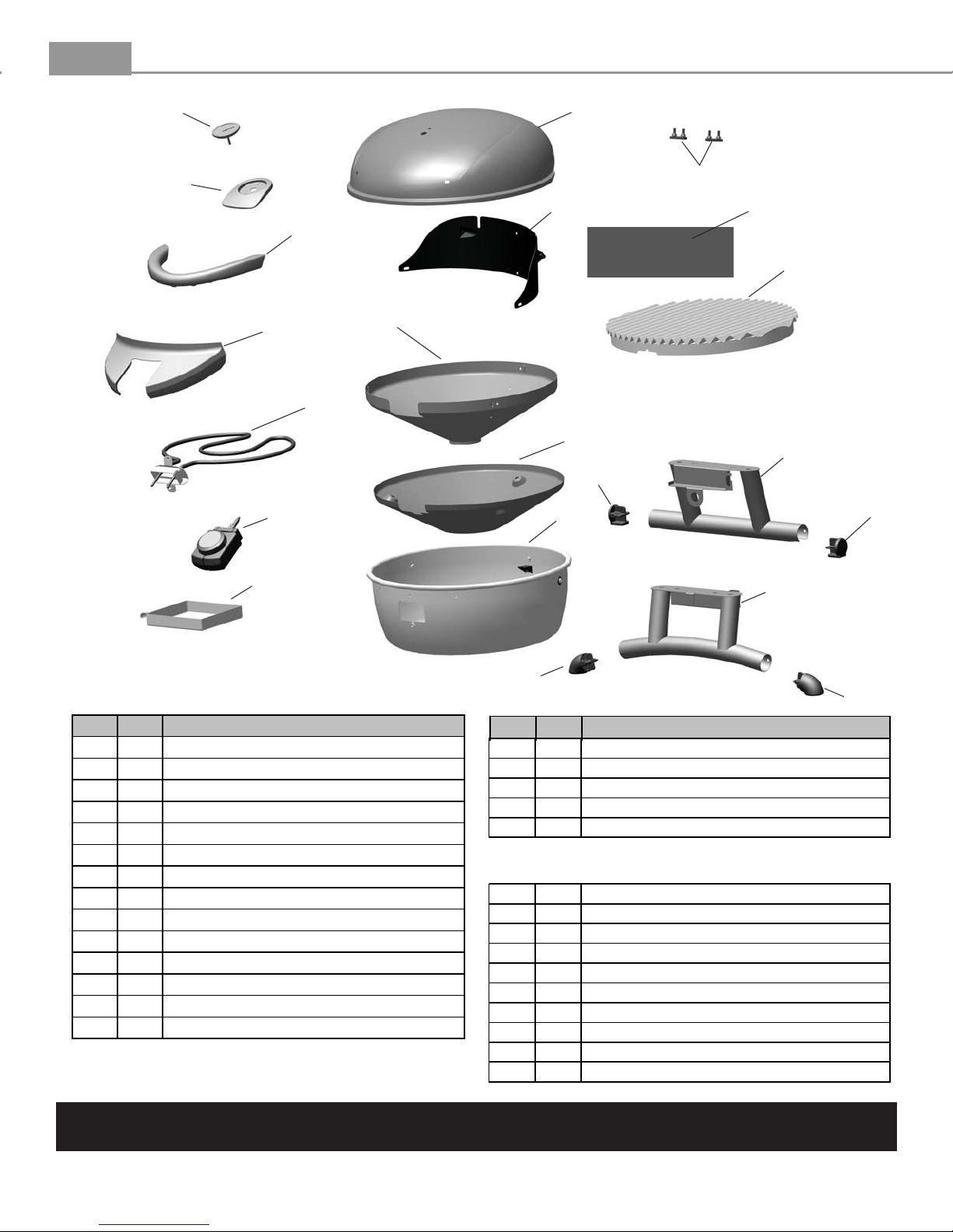
A 1
GRILL BOTTOM
B 1
HEAT SHIELD
C 1
INNER REFLECTOR
D 1
ELEMENT
E 1
CONTROL PANEL
F 1
THERMOSTAT
G 1
FRONT LEG ASSEMBLY
H 2
FRONT LEG CAP
I 1
REAR LEG ASSEMBLY
J 2
REAR LEG CAP
K 1
COOKING GRATE
L 1
GREASE TRAY
M 1
WIND SHIELD
N 1
WARMING RACK
O 1 TOP LID
P 1 LID HANDLE
Q 2 LID BUMPER
R 1 TEMPERATURE GAUGE
S 1 BEZEL, F/ TEMPERATURE GAUGE
… 1 HARDWARE PACK
… 1 ASSEMBLY GUIDE, ENGLISH
… 1 ASSEMBLY GUIDE, SPANISH-OPTIONAL
… 1 ASSEMBLY GUIDE, FRENCH-OPTIONAL
… 1 PRODUCT GUIDE, ENGLISH
… 1 PRODUCT GUIDE, SPANISH-OPTIONAL
… 1 PRODUCT GUIDE, FRENCH-OPTIONAL
… 1 GRILLING GUIDE, ENGLISH
… 1 GRILLING GUIDE, SPANISH-WEB ONLY
… 1 GRILLING GUIDE, FRENCH-WEN ONLY
NOT Pictured
ASSEMBLY GUIDE
Grill Parts Diagram
R
S
P
E
D
F
C
M
O
Q
N
K
B
J
A
I
J
L
NOTE: Some grill parts shown in the parts list may differ slightly in appearance from those on
G
H
H
your particular model.
Page 4

4
ASSEMBLY GUIDE
Part Qty
A1– 1
Lower Body
A2–
Front Leg Assembly
A3– 1
Rear Leg Assembly
1
GRILL LEG Assembly
Fasteners
screw
(qty 4)
10-24x1/2"
Step 1 - Place Lower Body (A1) upside down and attach Front Leg Assembly (A2) with two 10-
24x1/2” screws. Make sure Front Leg Assembly is toward front of Lower Body as shown.
10-24x1/2"
screw
(2 each)
A2
Leg properly positioned
A1A1
A1
Step 2 - With Lower Body (A1) still upside down attach Rear Leg Assembly (A3) with two #10-
24x1/2” screws. Make sure the Rear Leg Assembly is positioned as shown.
10-24x1/2"
screw
(2 each)
Legs properly positioned
A3
A3
A1
A1
TURN GRILL UPRIGHT
Page 5

5
ASSEMBLY GUIDE
Part Qty
GRILL BODY Assembly
Fasteners
B1– Lower Body 1
B2– Wind Shield 1
B3– Grill Lid 1
10-24x3/8"
screw
(qty 3)
1/4-20x1"
screw
(qty 2)
Fiber Washer
(qty 5)
1/4-20 Nut
(qty 2)
Step 3 - Attach Wind Shied (B2) inside the Lower Body (B1) by aligning the holes in the
Wind Shield with corresponding holes in the Lower Body. Place fiber washer over 10-24x3/8”
screw and then insert screw with washer through hole in the center of the back and secure
with 10-24 nut. Repeat for other 2 holes.
10-24x3/8"
Screws
(3 each)
B2
10-24 Nut
(qty 3)
Fiber
Washer
B1
10-24
Nuts
(3 each)
(3 each)
Step 4 - Attach the Grill Lid (B3) by aligning the hinge holes in the Grill Lid over the hinge pin in
the Wind Shield (B2). Insert fiber washer over 1/4-20x1” screw then insert screw through hinge pin
hole and secure using 1/4-20 nut from the inside of the grill. Repeat for other side.
Fiber
B3
Washer
(2 each)
1/4-20x1"
Screws
(2 each)
B2
1/4-20
Nuts
(2 each)
Page 6

4
6
ASSEMBLY GUIDE
GRILL FINAL Assembly
screw
(qty 2)
Fasteners
Fiber Washer
(qty 2)
Part Qty.
C1 – 1
C2 –
C3 –
Cooking Grate
Warming Rack
Handle
–
Grease tray
1
NOTE: The Cooking Grate
may have sharp edges. Be very
careful when handling the
1
Cooking Grate. You should
wear gloves when handling the
1C4
Cooking Grate.
10-24x3/8"
Step 5 - With Grill Lid open, place the Cooking Grate (C1) into the Lower Body, allowing it to
rest on the three brackets spaced around the Lower Body. Be sure the notch in the cooking grate
is facing the front of the grill. Place the Warming Rack (C2) on to position by first hooking the
center pin into the hole in the wind shield, then rotate the warming rack down into position, with
other pins secured in the slots.
C1
C2
Notch to the
front of grill
Step 6 - With Grill Lid open, install the Handle (C3)to the lid. Insert 2 10-24x3/8” screws from inside
the lid through the lid holes, and into the handle. Repeat for other side - tighten securely. Install
Grease Tray (C4) by sliding the tray onto the Grease tray rails from the side of the grill.
C3
Fiber washers
10-24x3/8” screws
C4
Page 7

7
ASSEMBLY GUIDE
Part Qty.
GRILL FINAL Assembly
C5 –
Controller
1
Step 7 - Install the Controller (C5) into the receptacle. The control knob should be facing up as
you engage the tip of the controller into the receptacle. Push the controller in all the way until you
hear a click, this will ensure your controller is installed properly.
C5
Receptacle
Controller
Controller Tip
Ground Fault Interrupter
Since 1971 the National Electric Code (NEC) has
required Ground Fault Interrupter devices on all
outdoor circuits.
If your residence was built before 1971, check with a
qualified electrician to determine if a Ground Fault
Interrupter protector exists.
Do not use this appliance if the circuit does not
have GFI protection.
Do not plug this appliance into an indoor circuit.
Page 8

 Loading...