

Page 1
assembly
guide
Model Number:
11601558
11601558-A1
11601579
Propane cylinder
sold separately.
Estimated time required for assembly: 1 Hour
PROPANE
(English)
42804394 • 06/02/2010
Page 2
2
ASSEMBLY GUIDE
A, B, C, Assembly:
CAUTION: For your safety, before operating, Read Product Guide & Outdoor Cooking Guide
provided with this grill.
*SAFETY First…..Grill components may have sharp edges. Be careful when handling grill parts
during assembly. We suggest that you wear a sturdy pair of leather gloves while handling the grill parts.
BEFORE You begin assembly of your grill….
1. Carefully remove all components from the carton.
2. Familiarize yourself with the components and hardware used for assembly.
3. Please note that hardware used for assembly may not be shown actual size..
4. After removing components from the carton, split the carton open and use it as
a soft, scratch-free work pad to assemble your grill.
BEFORE You Grill….
1. Read Product Guide & Outdoor Cooking Guide
2. Position Grill Safely away from walls & structures (Ref. Product Guide)
3. Pre– Heat Grill—15 minutes on 5 , High to season grill.
TIPS & Tricks…...
First Take a moment to record the serial number here: _______________________________
When grilling, preheat your grill for 10 to 15 minutes with the lid down.
Go to charbroil.com to register your grill.-
After grilling—the Bistro can be turned on 5 , High for cleaning and burning off
the grates. - Use a wire brush to brush off the grates.
A light coat of oil on the grate will help prevent foods like fish and vegetables from
sticking to the grate.
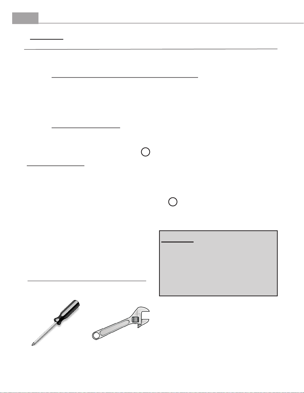
TOOLS REQUIRED FOR ASSEMBLY
(Not Supplied)
NOTE….
Installer: Leave instructions with the grill.
Consumer: Retain instructions for reference.
Grill must be installed in accordance with local
codes…..
Designed for outdoor use only…
Read all instructions before operating…
Phillips Head
Screwdriver
Small Adjustable
Visit www.sizzleonthegrill.com/user-forums to chat with Patio Bistro® owners just like you!
Wrench
Page 3
FF
3
ASSEMBLY GUIDE
A
T
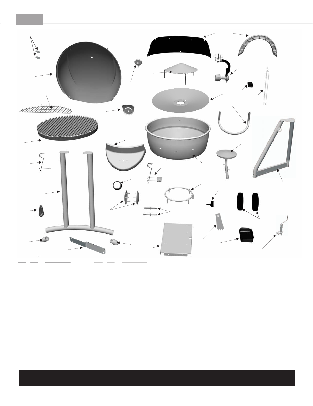
Grill Parts Diagram
K
H
S
C
V
I
CC
J
G
X
W
DD
L
F
B
D
N
Y
E
P
GG
BB
AA
Key Qty Description
A 1 Grill Lid
B 1 Lower Body
C 1 Heat Tent
D 1 Burner
E 1
F 1 Ignition Harness
G 1 Bezel
H 1 Wind Shield
I 1 Inner Reflector
J 1 Towel Bar
K 1 Lid Handle
L 1 Control Panel
M 2 Wheel
N 1 Control Knob
Tank Retainer Bolt
R
BB
Key Qty Description
O 1 Rear Leg Set
P 1 Front Leg Set
Q 1 Grease Tray
R 2 Hubcap
S 1 Hose, Valve, Regulator Assembly
T 1 Warming Rack
U 2 Axle
V 1 Heat Indicator
W 1 Cooking Grate
X. 1 Match Holder
Y 1 Tank Retainer Ring
Z 1 Cart Base
AA 1 Cart Bracket
BB 2 Leg Cap
Z
U
HH
Key Qty Description
CC 1 Ignition Module
DD 1
EE 1
FF 2 Lid Bumper
GG 1 Match Light Hole Cover
HH 1 Grate Cleaning Tool
... 1 Hardware Pack
... 1 Assembly Manual, English
... 1 Assembly Manual, Spanish, Optional
... 1 Assembly Manual, French, Optional
... 1 Grilling Guide
... 1 Product Guide, English
... 1 Product Guide, Spanish
... 1 Product Guide, French
Q
Electrode Wire
Ignitor Electrode
NOTE: Some grill parts shown in the assembly steps may differ slightly in appearance from
those on your particular model. However, the method of assembly remains the same.
Visit www.sizzleonthegrill.com/user-forums to chat with Patio Bistro® owners just like you!
O
M
EE
, Optional
, Optional
Page 4

4
ASSEMBLY GUIDE
Part Qty
A1–
A2– Cart Base 1
A3–
A4– Front Leg Set 1
A6– Wheels 2
–
A7
A1
A2
Tank Retainer Ring
Tank Retainer Bolt
A5– Rear Leg Set 1
Hubcap
1
1
A3
2
Step 1
GRILL CART Assembly
.
Wheel Retaining
1/4x20-1/2"
1/4-20 Nut
screw
(qty 4)
(qty 4)
Clip
(qty 2)
3/8-16 Nut
Axle Bolt
(qty 2)
Assemble Tank Retainer Ring (A1) to the Cart Base (A2)
by aligning studs into corresponding holes. Secure with 4
each, 1/4-20 nuts using a small adjustable wrench, not
supplied.
Thread the Tank Retainer Bolt (A3) into the Tank
Retainer Ring(A1)
(qty 2)
1/4-20 Nuts
(4 each)
Step 2
Attach Front Leg Set (A4) to the Cart Base (A2) using 2 1/4-20 screws. Attach Rear Leg Set (A5) to
the Cart Base (A2) in the same manner, using 2 1/4-20 screws.
Attach 2 Axle Bolts to the Rear Leg Set (A5), thread a 3/8-16 nut as shown and tighten securely using
a small adjustable wrench.
Slide a Wheel (A6) over an Axle Bolt and secure using a Wheel Retaining Clip. Repeat for other side.
Position and Snap into place the Wheel Hubcaps (A7).
After cart assembly, if
your cart does not sit
level, use these screws to
adjust the cart.
A4
A5
Axle Nut
3/8-16
Axle Bolt
A2
1/4-20 Screws
(4 each)
Position wheel
as shown
Wheel
Retaining
Clip install after
placing wheel on
the axle.
A6
A7
Visit www.sizzleonthegrill.com/user-forums to chat with Patio Bistro® owners just like you!
Page 5

5
ASSEMBLY GUIDE
–
A8
–
A9
Part Qty
Cart Bracket
Leg End Cap
A8
GRILL CART Assembly
.
1
2
1/4-20 Nut
1/4-20 Nut
(qty 4)
Step 3 - Carefully turn the Cart Assembly over
and allow it to rest on the tops of the leg
assemblies. Assemble the Cart Bracket (A8) to
the Cart Assembly by by inserting 4 each 1/4-
20x2" screws int0 into corresponding holes as
shown. Allow the Cart Bracket to rest on the
floor, this will help with alignment. Secure with 4
each, 1/4-20 nuts using a small adjustable
wrench, not supplied. FINGER TIGHTEN ONLY
AT THIS TIME. The bracket will be tightened in
step B2.
Be sure to install Cart Bracket (A8) on the side
opposite of the ignition module bracket. Once
complete -leave the cart in the upside down
position.
Lastly, insert the Leg End Caps (A9) into the front
legs and secure with 1 each #10x3/8" screw.
1/4x20-2"
screw
(qty 4)
#10x3/8"
screw
(qty 2)
A9
Ignition Module
Bracket
#10x3/8" screws
1/4-20x2"
screws
Place the Lower Body on the carton
pad upside down in preparation for
the next step.
Visit www.sizzleonthegrill.com/user-forums to chat with Patio Bistro® owners just like you!
Page 6

6
ASSEMBLY GUIDE
Part Qty.
GRILL BODY Assembly
.
B1– Lower Body 1
B2– Wind Shield 1
B3– Grill Lid 1
ASSEMBLY
Step 1 - Attach the Lower Body (B1) to the Cart Assembly
by aligning the studs on the bottom of the grill with the
corresponding holes in the tops of the leg assemblies. Secure
with 7 each 10-24 nuts. A Nut Driver (not supplied) will work
nicely for this step.
Studs
located on
Lower
Body.
B1
10-24x3/8"
screw
(qty 3)
1/4-20x3/4"
Hinge
screw
(qty 2)
Fiber Washer
(qty 5)
1/4-20 Nut
(qty 2)
10-24 Nut
(qty 10)
Step 3 - Attach the Wind Shield (B2) to the Lower Body
(B1) by aligning the holes in the panels with the corresponding
holes in the Lower Body. Secure with 3 10-24 nuts, 3 10-
24x3/8" Screws, and fiber washers. The Wind Shield will
rest inside the Lower Body.
10-24
Nuts
(3 each)
B2
10-24x3/8"
Screws
(3 each)
Step 2 - With the legs assembled to the Lower
Body, tighten the 4 screws holding the Cart
Bracket in place. Once complete, turn the grill over
to the upright position.
Cart
Bracket
B1
Fiber
Washer
(3 each)
B1
Step 4 - Attach the Grill Lid (B3) by aligning the hinge
holes in the lid to the matching holes in the Wind Shield
(B2). Insert 2 Hinge Screws into the holes and secure with 2
1/4-20 nuts and two Fiber washers from the inside of the
grill.
B3
Fiber
Washer
(2 each)
1/4-20x3/4"
Hinge
Screws
(2 each)
Visit www.sizzleonthegrill.com/user-forums to chat with Patio Bistro® owners just like you!
1/4-20
Nuts
(2 each)
Page 7

7
ASSEMBLY GUIDE
GRILL FINAL Assembly
Part Qty.
NOTE: The Cooking Grate may have sharp edges. Be
very careful when handling the Cooking Grate. You
C1 –
C2 – Cooking Grate 1
C3 – Warming Rack 1
C4 –
C5 – Grease tray 1
Heat Tent
Control Knob
1
1
should wear gloves when handling the Cooking Grate.
The cooking grate ridges should run from front to back of
the grill as shown below. Be sure that the cooking grate
rests squarely on the brackets spaced around the lower
body. This will make for easier grate cleaning as well.
Step 1 - With the Grill Lid open, place the legs of the Heat Tent (C1) into the matching impressions in the Lower Body. Next,
Place the Cooking Grate (C2)into the Lower Body. The cooking grate ridges should run from front to back of the grill as shown
below. Be sure that the cooking grate rests squarely on the three brackets spaced around the Lower Body.
Ridges front to
back
C1
C2
Step 2 - Place the Warming Rack (C3) into position by first hooking the center pins into the windshield, then rotate the
warming rack down into position. Next, Press the Control Knob (C4) onto the valve stem.
Install the Grease Tray (C5) by sliding the tray onto the Grease Tray Rails from the rear of the grill. Note: The grease tray
rests between the grease tray rail stops. See detail shown in Figure A.
C3
Note: The control
knob may be
factory assembled
C4
Fig. A
Grease
Tray
Rails
C5
Grease
Tray
Rail Stops
Visit www.sizzleonthegrill.com/user-forums to chat with Patio Bistro® owners just like you!
Page 8

8
ASSEMBLY GUIDE
GRILL FINAL Assembly
Part Qty.
C6 –
C7 –
C8 –
Battery
Electronic Ignition Module
Lid Handle
1
1
1
10-24x3/8"
screw
(qty 2)
Fiber Washer
(qty 2)
NOTE: The Ignition wiring shown below will only fit into the module one way. Be sure the
wires are routed away from the heat source. Do not allow the wires to rest against hot areas of
the grill.
Step 3 - Install the Electronic Ignition Module, Unscrew the Battery Cap and module nut from the module. Insert the
module into the module bracket. Secure with the module nut. Install the Battery (C6) in the Electronic Ignition Module
(C7) with the negative end first. Screw the Battery Cap back into place. Install the ignition wires as shown below.
Battery
Ignitor
Electrode
Ignitor Wire to
Ignitor Electrode
+
Battery
C6
-
C7
Cap
Module
Nut
Ignition Wires from
Control Panel
Rear of Ignition
Module shown
Step 4 - Install the Lid Handle (C8) with 2 10-24x3/8" screws and 2 fiber washers as shown. Install the propane cylinder.
Be sure to loosen the tank retaining bolt far enough to allow the cylinder to rest securely on the cart base. Tighten the tank
retaining bolt and attach the propane regulator (not shown) when you are ready to use the grill.
Cylinder valve
facing RH side
of grill.
C8
10-24x3/8"
Fiber
Washer
(2 each)
Congratulations! You have successfully completed the assembly of your grill. Prior to using your grill, be sure to follow the
Screws
(2 each)
20lb.Propane
Cylinder
Loosen Tank Retaining Bolt,install cylinder, then tighten.
leak check instructions found in the Care and Use Guide.
Visit www.sizzleonthegrill.com/user-forums to chat with Patio Bistro® owners just like you!
 Loading...