

Page 1
Chapter
C
US
Chapter
Chapter
GettinG Started
1
1
1
In this Chapter...
Introduction .................................................................................................................. 1-2
The Purpose of this Manual ����������������������������������������������������������������������������������������� 1-2
Supplemental Manuals ������������������������������������������������������������������������������������������������ 1-2
Technical Support �������������������������������������������������������������������������������������������������������1-2
Conventions Used ......................................................................................................... 1-3
Key Topics for Each Chapter ����������������������������������������������������������������������������������������1-3
Agency Approvals ......................................................................................................... 1-4
Quick Start Steps ..........................................................................................................1-5
Step 1 – Unpack and Inspect ���������������������������������������������������������������������������������������1-5
Step 2 – Become Familiar with Available Communication Ports �����������������������������������1-6
Step 3 – Install C-more Micro Panel ����������������������������������������������������������������������������1-8
Enclosure Clearances ��������������������������������������������������������������������������������������������������� 1-9
Step 4 – Install the Programming Software and Develop a Project ���������������������������� 1-11
Step 5 – Connect C-more Micro to Computer ����������������������������������������������������������1-12
Step 6 – Provide Power to the C-more Micro Panel ���������������������������������������������������1-14
Step 7 – Accessing the C-more Micro Panel Setup Screens ���������������������������������������1-16
Step 8 – Choose C-more Micro Panel to PLC Protocol & Cables �������������������������������1-17
Step 9 – Connect C-more Micro Panel to PLC ����������������������������������������������������������� 1-19
U
R
L
Page 2

Chapter 1 - Getting Started
EA3-USER-M Hardware User Manual, 2nd Ed. Rev. L
Introduction
1
2
3
4
5
6
7
8
9
10
11
12
13
The Purpose of this Manual
Thank you for purchasing from our C-more® Micro family of products. This manual
describes AutomationDirect.com’s C-more Micro panels, specifications, included
components and available accessories and provides you with important information for
installation, connectivity and setup. The manual shows you how to install, wire and use
the products. It also helps you understand how to interface the panels to other devices in a
control system.
This user manual contains important information for personnel who will install the panels
and accessories, and for the personnel who will be programming the panel. If you understand
control systems making use of operating interfaces such as the C-more Micro panels, our
user manuals will provide all the information you need to get, and keep, your system up and
running.
Supplemental Manuals
If you are familiar with industrial control type devices, you may be able to get up and running
with just the aide of the Quick Start Guide that is included with each panel. You may also
refer to the online help that is available in the C-more Micro programming software.
Technical Support
We strive to make our manuals the best in the industry. We rely on your feedback to let
us know if we are reaching our goal. If you cannot find the solution to your particular
application, or, if for any reason you need technical assistance, please call us at:
770–844–4200
Our technical support group will work with you to answer your questions. They are available
Monday through Friday from 9:00 A.M. to 6:00 P.M. Eastern Time. We also encourage you
to visit our web site where you can find technical and non-technical information about our
products and our company.
http://c-moremicro.automationdirect.com
14
A
B
C
D
1-2
®
Page 3
EA3-USER-M Hardware User Manual, 2nd Ed. Rev. L
Conventions Used
Chapter 1 - Getting Started
1
When you see the “notepad” icon in the left-hand margin, the paragraph to its immediate right will be a special note.
The word NOTE: in boldface will mark the beginning of the text.
When you see the “exclamation mark” icon in the left-hand margin, the paragraph to its immediate
right will be a warning. This information could prevent injury, loss of property, or even death (in
extreme cases). The words Warning: or Caution: in boldface will mark the beginning of the text.
Key Topics for Each Chapter
The beginning of each chapter will list the key topics
that can be found in that chapter.
• TFT color display
• LED backlight
• Selectable Portrait or Landscape orientation
• Requires 12 - 24 VDC Class 2 power supply
• USB Type B programming port
• Built in 15-pin serial communications port (RS-232/422/485)
• Built in RJ12 port
• Five or Seven user-defined function keys, each with a user-programmable red LED
• Optional replaceable clear screen overlay
• Built in Alarm Control setup that activates beep, backlight flash, customized alarm banner, and red
LED blinking
• Up to 999 screens, limited only by memory usage
• 0 to 50 °C (32 to 122 °F) operating temperature range
• UL, cUL & CE agency approvals (see Panel Specifications and Agency Approvals sections for
details)
• 2-year warranty from date of purchase
Getting Started
In This Chapter...
General Information
.................................................................1-2
...........................................................................1-4Specifications
CHAPTER
1
2
3
4
5
6
7
8
9
10
11
12
13
14
A
B
C
D
®
1-3
Page 4
Chapter 1 - Getting Started
EA3-USER-M Hardware User Manual, 2nd Ed. Rev. L
Agency Approvals
1
2
3
4
5
6
7
8
9
10
11
Certifications
Name UL / cUL UL508 UL61010 CE ISO-9000
EA3-S3ML-RN, EA3-S3ML-R, EA3-S3ML, EA3-T4CL
EA3-T6CL, EA3-T8CL, EA3-T10CL E157382 N/A
E157382
N/A E157382
Yes Yes
12
13
14
A
B
C
D
1-4
®
Page 5
EA3-USER-M Hardware User Manual, 2nd Ed. Rev. L
Quick Start Steps
Chapter 1 - Getting Started
Step 1 – Unpack and Inspect
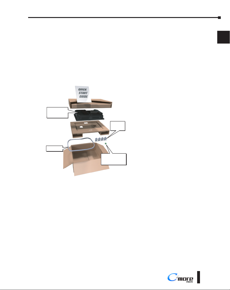
a.) Unpack the C-more Micro panel from its shipping carton. Included in the carton are the
following:
• C-more Color Micro panel
• DC power connector
• mounting clips
• gasket
• Quick Start Guide
b.) Unpack any accessories that have been
ordered, such as: programming cable, PLC
communications cable, etc.
c.) Inspect all equipment for completeness.
C-more
EA3 series
Panel
Gasket ¹
Mounting
Clips
EA-MG-DC-CON ²
DC Power
Connector
If anything is missing or damaged,
immediately call the AutomationDirect®
returns department @ 1-800-633-0405.
1
2
3
4
5
6
7
8
9
10
11
1. Not included with EA3-S3ML-RN
2. Not included with EA3-S3ML-RN and EA3-S3ML-R
12
13
14
A
B
C
D
®
1-5
Page 6
Chapter 1 - Getting Started
EA3-USER-M Hardware User Manual, 2nd Ed. Rev. L
Step 2 – Become Familiar with Available Communication Ports
EA3-S3ML-RN and EA3-S3ML-R
1
2
3
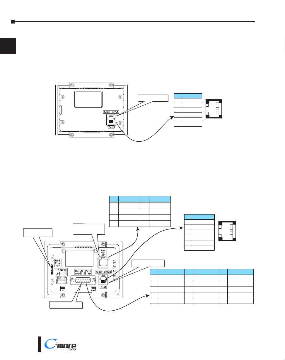
EA3-S3ML-RN and EA3-S3ML-R C-more Micro panels include a built-in RJ12 RS-232
serial communications port designated as Port 1. The EA-MG-PGM-CBL programming cable
assembly connects to this port for programming the C-more Micro with a PC. In operation,
the DV-1000CBL cable is used to connect to any AutomationDirect PLC with an RJ12 port.
These panels are powered through Port1 when using either of these cables.
4
5
6
7
8
9
10
11
12
13
14
A
B
C
EA3-S3ML and EA3-T4CL
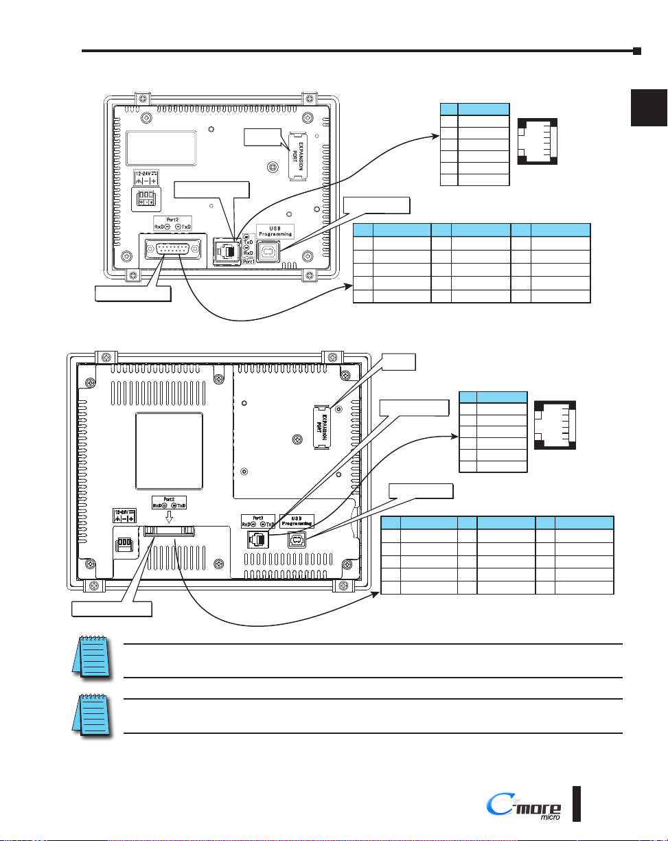
EA3-S3ML, EA3-T4CL, EA3-T6CL, EA3-T8CL and EA3-T10CL C-more Micro panels
include a built-in USB Type B port used to communicate with a PC during project
development. There is a 15-pin RS-232/RS-422/RS-485 port and an RJ12 RS-232 port for
communications to a PLC.
USB Type Micro-B
Programming Port
Communications Port
81
15
PLC 15-pin serial
communications Port2
Ethernet
Programming /
9
communications Port1
Ethernet 10/100 Base-T
Pin Signal
1 TD+
TD–
2
RD+
3
do not use
4
PinSignal
5do not use
6
7
8
RJ12 serial
communications Port1
RJ12 serial
RD–
N.C.
N.C.
Pin Signal
1Frame GND
2
3
4
5 Logic GND
TXD (232C)
RXD (232C)
do not use
Pin Signal
1Logic GND
Power Detect*
2
RXD (232C)
3
TXD (232C)
4
5+5VDC in
6Logic GND
RS-232
Pin Signal
1 Logic GND
Power Detect*
2
RXD (232C)
3
TXD (232C)
4
5+5VDC in*
6 Logic GND
PinSignal PinSignal
6LE
CTS (232C)
7
RTS (232C)
8
RXD+ (422/485)
9
10 RXD– (422/485)
6 5 4 3 2 1
RS-232
RS-232/422/485
6 5 4 3 2 1
* EA3-T4CL
not used
11 TXD+ (422/485)
TXD– (422/485)
12
Term. Resistor
13
do not use
14
15 do not use
D
1-6
®
Page 7
EA3-USER-M Hardware User Manual, 2nd Ed. Rev. L
EA3-T6CL
RS-232/422/485
Chapter 1 - Getting Started
RJ12 serial
communications Port1
-+
81
9
15
PLC 15-pin serial
communications Port2
EA3-T8CL and EA3-T10CL
Expansion
Connector
USB Type B
Programming Port
Pin Signal
1Frame GND
TXD (232C)
2
RXD (232C)
3
do not use
4
5 Logic GND
Expansion
Connector
communications Port1
PinSignal PinSignal
10 RXD– (422/485)
RS-232/422/485
RJ12 serial
USB Type B
Programming Port1
Pin Signal
1 Logic GND
not used
2
RXD (232C)
3
TXD (232C)
4
5Supplies +5VDC
6 Logic GND
RS-232
6LE
CTS (232C)
7
RTS (232C)
8
RXD+ (422/485)
9
Pin Signal
1 Logic GND
not used
2
RXD (232C)
3
TXD (232C)
4
5 Supplies +5VDC
6 Logic GND
RS-232
6 5 4 3 2 1
11 TXD+ (422/485)
TXD– (422/485)
12
Term. Resistor
13
do not use
14
15 do not use
6 5 4 3 2 1
1
2
3
4
5
6
7
8
9
10
11
PLC 15-pin D-sub
serial communications Port2
NOTE: See Chapter 2: Specifications and Chapter 6: PLC Communications for additional details on the available
communication ports, protocols and cables.
NOTE: The panel has a built-in RJ12 serial communications port (Port1 - RS-232) and a built in 15-pin serial
communications port (Port2 - RS-232/422/485). Only one of the ports can be used with a connected PLC.
Pin Signal
1 Frame GND
TXD (232C)
2
RXD (232C)
3
do not use
4
5 Logic GND
Pin Signal Pin Signal
6 LE
CTS (232C)
7
RTS (232C)
8
RXD+ (422/485)
9
10 RXD– (422/485)
11 TXD+ (422/485)
TXD– (422/485)
12
Term. Resistor
13
do not use
14
15 do not use
®
12
13
14
A
B
C
D
1-7
Page 8
Chapter 1 - Getting Started
EA3-USER-M Hardware User Manual, 2nd Ed. Rev. L
C C
Step 3 – Install C-more Micro Panel
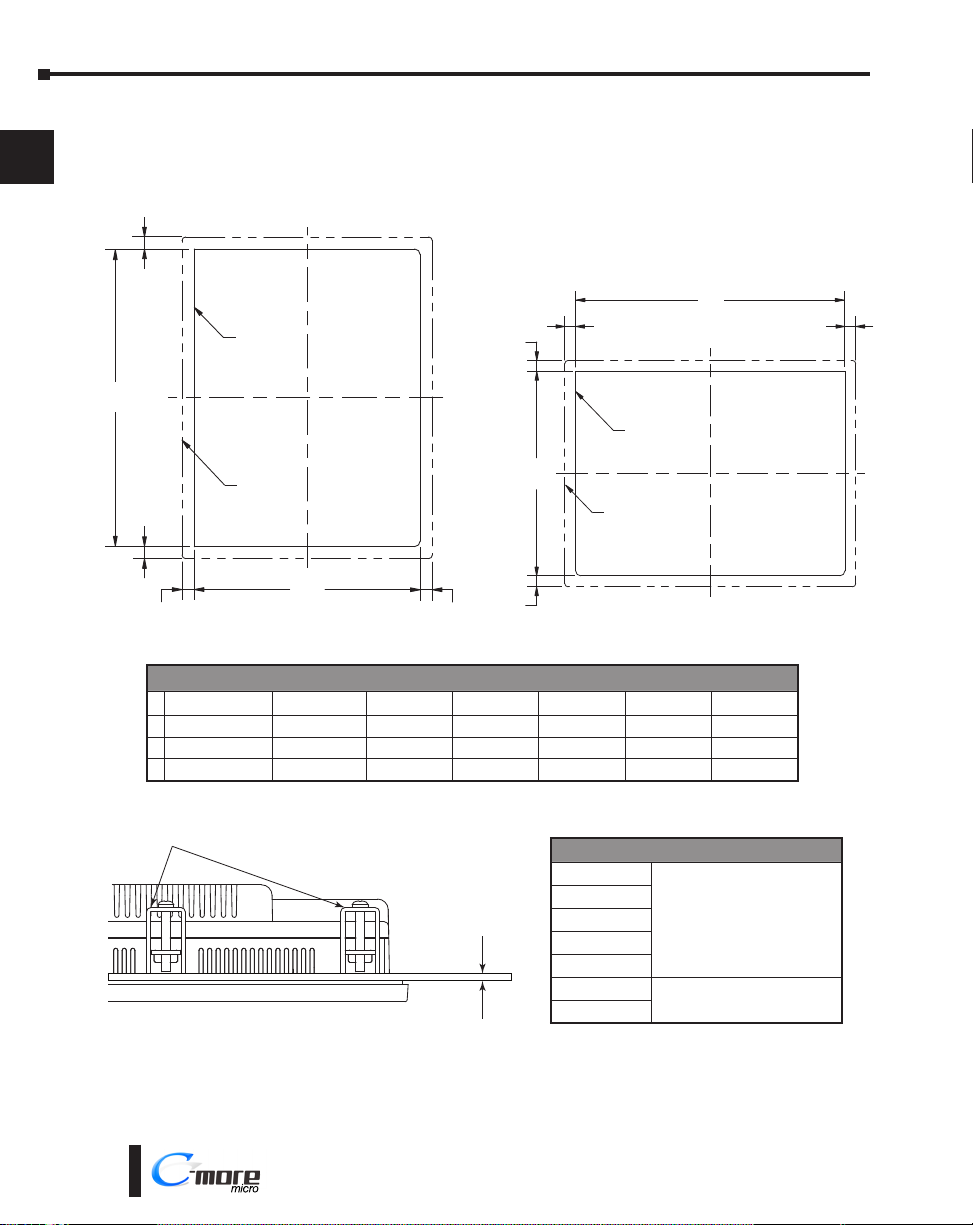
The C-more Micro panel can be mounted through a cutout in an enclosure by using the
1
dimensions that follow.
See Chapter 2: Specifications for additional product dimensions.
2
3
4
5
6
7
8
9
10
11
12
13
14
A
B
C
C
CUTOUT
OUTLINE
A
BEZEL
OUTLINE
C
CUTOUT
B
C
B
C
C C
CUTOUT
OUTLINE
BEZEL
OUTLINE
A
CUTOUT
Landscape Mode (Horizontal) Portrait Mode (Vertical)
Cutout Dimensions inches [mm]
EA3-S3ML-RN EA3-S3ML-R EA3-S3ML EA3-T4CL EA3-T6CL EA3-T8CL EA3-T10CL
A
4.02 [102.0] 4.02 [102.0] 4.02 [102.0] 4.02 [102.0] 6.34 [161.0] 9.25 [235.0] 11.91 [302.5]
B
2.76 [70.0] 2.76 [70.0] 2.76 [70.0] 2.76 [70.0] 4.81 [122.2] 7.07 [179.6] 8.92 [226.6]
C
0.24 [6.0] 0.24 [6.0] 0.24 [6.0] 0.36 [9.2] 0.26 [6.6] 0.31 [7.9] 0.31 [7.9]
The enclosure mounting thickness range for the panels is 0.04”–0.2” [1–5 mm].
Mounting Clip
Enclosure
Thickness Range
Mounting Screw Tightening Torque
EA3-S3ML-RN
EA3-S3ML-R
EA3-S3ML
EA3-T4CL
EA3-T6CL
EA3-T8CL
EA3-T10CL
21 - 28 oz·in (0.15 - 0.20 N·m)
63 - 77 oz·in (0.45 - 0.55 N·m)
D
1-8
®
Page 9
Chapter 1 - Getting Started
EA3-USER-M Hardware User Manual, 2nd Ed. Rev. L
Enclosure Clearances
EA3-S3ML-RN, EA3-S3ML-R, EA3-S3ML, EA3-T4CL and EA3-T6CL
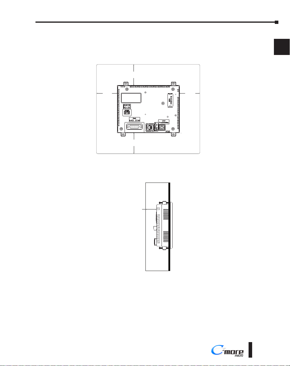
In all installations, 1.2” [30.0 mm] minimum clearance is required inside an enclosure for
proper ventilation of C-more Micro panels.
Enclosure
1.2”
[30 mm]
1.2”
[30 mm]
1.2”
[30 mm]
1
2
3
4
-+
1.2”
[30 mm]
Rear View
A 1.2” [30.0 mm] minimum clearance is required at the rear of a panel for proper ventilation
of C-more Micro panels.
Enclosure
1.2”
[30.0 mm]
Side View
5
6
7
8
9
10
11
12
13
14
A
B
C
D
®
1-9
Page 10
Chapter 1 - Getting Started
EA3-USER-M Hardware User Manual, 2nd Ed. Rev. L
Enclosure Clearances (cont’d)
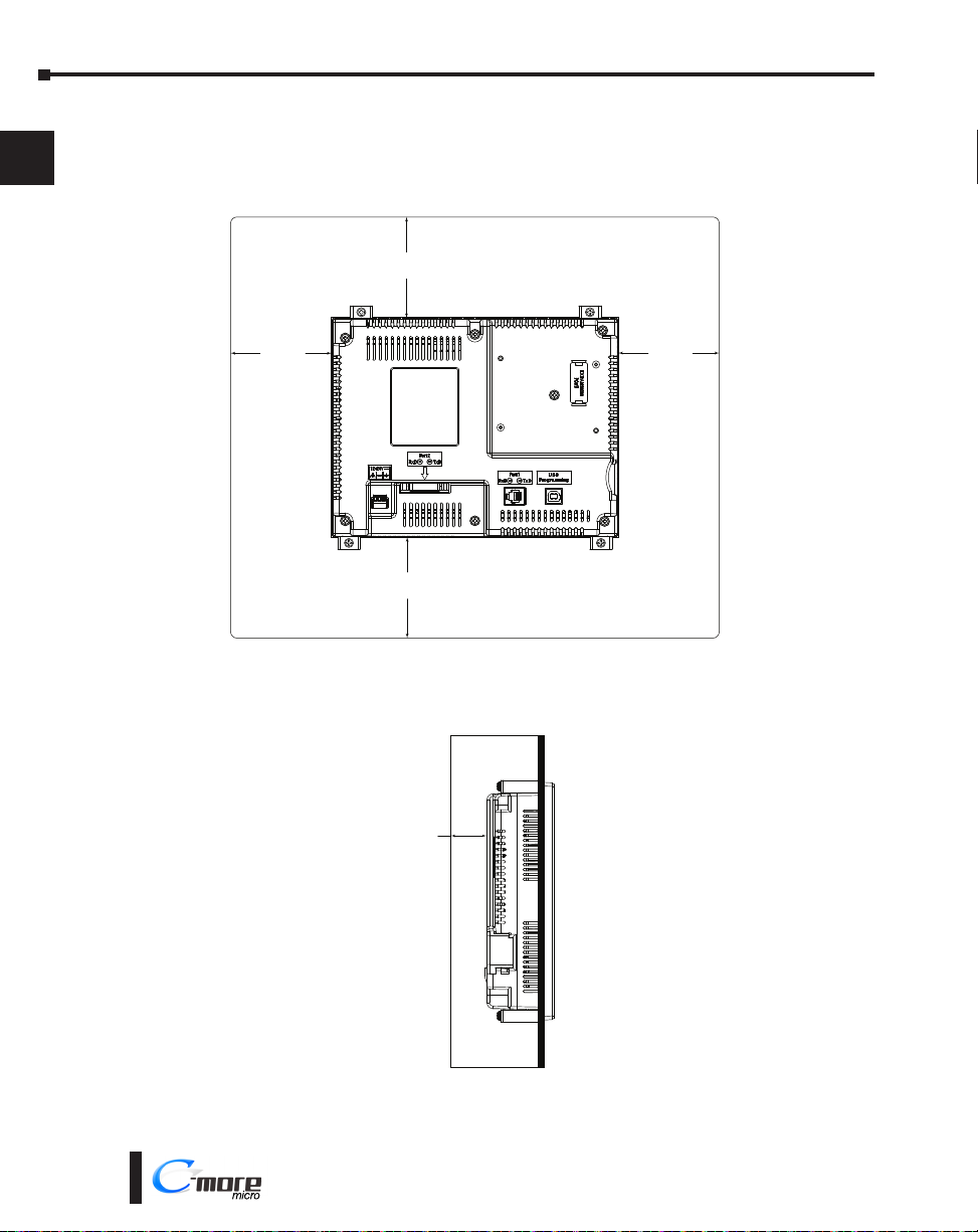
EA3-T8CL and EA3-T10CL
1
In all installations, 4.0” [101.6 mm] minimum clearance is required inside an enclosure for
proper ventilation of 8-inch and 10-inch C-more Micro panels.
2
3
4.0”
[101.6 mm]
Enclosure
4
5
6
7
8
9
10
11
12
13
14
4.0”
[101.6 mm]
4.0”
[101.6 mm]
4.0”
[101.6 mm]
Rear View
1.72” [43.7 mm] minimum clearance is required at the rear of a panel for proper ventilation
of 8-inch and 10-inch C-more Micro panels.
Enclosure
1.72”
[43.7 mm]
A
B
C
D
1-10
®
Side View
Page 11
Chapter 1 - Getting Started
EA3-USER-M Hardware User Manual, 2nd Ed. Rev. L
Step 4 – Install the Programming Software and Develop a Project
C-more Micro Programming Software is available for free download at
http://support.automationdirect.com/products/cmoremicro.html
Part Number
EA3-S3ML-RN 4.30 or later
EA3-S3ML-R 4.30 or later
EA3-S3ML 4.20 or later
EA3-T4CL 4.20 or later
EA3-T6CL 3.6 or later
EA3-T8CL 3.5 or later
EA3-T10CL 3.5 or later
Following are the system requirements for running C-more Micro Programming Software,
EA-MG-PGMSW, on a PC:
• Operating System - Windows® 7 (32 and 64 bit), Windows 8 (32 and 64 bit); Windows 8.1
(32 and 64 bit), Windows 10
• Minimum 150 MB free hard-disk space
• CD-ROM or DVD drive for installing software from the CD, or internet access to download free
programming software
• USB port or Ethernet port if using optional EA-ECOM for project transfer from software to touch
panel
Insert the C-more Micro Programming Software CD-ROM into the PC’s CD-ROM drive
or download the programming software from www.automationdirect.com and follow the
instructions. If you need assistance during the software installation, please refer to the supplied
Software Installation Guide or call the AutomationDirect Technical Support team at
770-844-4200.
NOTE: The USB Type B programming port has an internal USB to serial converter. When the device is properly
installed and the USB programming cable connects the panel to the PC, the port will be identified as a serial
communications port with an assigned COM port number.
Panel Software / Firmware
Version Required
1
2
3
4
5
6
7
8
9
10
11
12
13
®
14
A
B
C
D
1-11
Page 12
Chapter 1 - Getting Started
EA3-USER-M Hardware User Manual, 2nd Ed. Rev. L
US
B
Cable
Step 5 – Connect C-more Micro to Computer
1
2
3
4
5
6
7
8
9
10
11
NOTE: Install C-more Micro Programming software before connecting the panel to the PC to ensure that the panel
drivers install correctly.
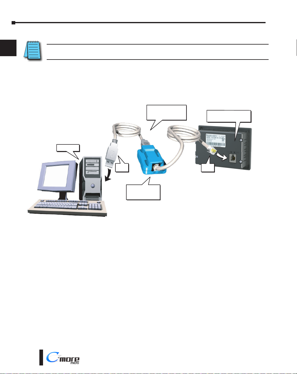
EA3-S3ML-RN and EA3-S3ML-R
Use an EA-MG-PGM-CBL, USB to RS-232 Programming Cable Assembly, from an USB port
type A on the project development PC, through the supplied converter, to the RJ12 RS-232
programming/PLC serial communications port on the C-more Micro-Graphic panel as shown
below.
PC to Panel Programming
Cable Assembly
User PC
USB
Cable
USB to RS232
Converter
(Includes serial & USB cables)
p/n EA-MG-PGM-CBL
EA3-S3ML-R(N)
C-more Micro Panel
Serial
Cable
12
13
14
A
B
C
D
1-12
®
Page 13
Chapter 1 - Getting Started
EA3-USER-M Hardware User Manual, 2nd Ed. Rev. L
EA3-S3ML and EA3-T4CL
Ethernet: Connect the PC RJ45 Ethernet port to the C-more Micro panels built-in RJ45 Ethernet
port.
USB Type B port: Connect the PC USB Type A port to the panels USB type micro B port using
a standard USB A to micro B USB cable. Maximum micro USB cable length
should not exceed six feet. See part number USB-CBL-AMICB6 on the
AutomationDirect web store.
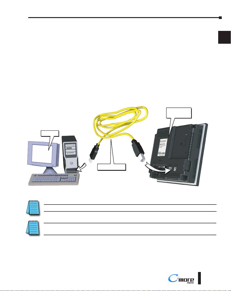
EA3-T6CL, EA3-T8CL and EA3-T10CL
Ethernet (Optional): Purchase the EA-ECOM Ethernet Option Module from AutomationDirect to
connect the PC to the C-more Micro Panels.
USB Type A port: Connect the PC USB Type A port to the panels USB Type B port using
standard USB Type A to Type B cables. See part number USB-CBL-AB6 on the
AutomationDirect web store.
C-more
Micro Panel
1
2
3
4
5
6
7
User PC
USB-CBL-AB6
NOTE: EA3-S3ML and EA3-T4CL are programmable via the built-in Ethernet port.
NOTE: Adding the optional EA-ECOM module to the EA3 6, 8 and 10-inch models allows programming via an
Ethernet connection with Cat5e cable.
8
9
10
11
12
13
14
A
B
C
D
®
1-13
Page 14
Chapter 1 - Getting Started
EA3-USER-M Hardware User Manual, 2nd Ed. Rev. L
To C-more
Step 6 – Provide Power to the C-more Micro Panel
EA3-S3ML-RN and EA3-S3ML-R
1
2
3
4
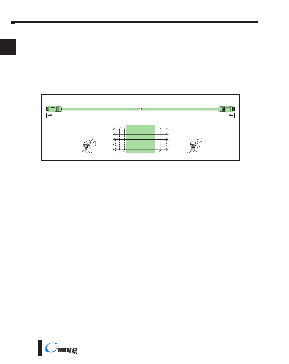
• EA3-S3ML-RN and EA3-S3ML-R C-more Micro panels are powered during programming from the
PC through the USB to RS-232 Programming Cable Assembly, EA-MG-PGM-CBL.
• During operation, EA3-S3ML-RN and EA3-S3ML-R C-more Micro panels can be powered
from most AutomationDirect PLC’s RJ12 serial communications port by using a DV-1000CBL
communications cable, or a DV-1000CBL communications cable with a FA-15HD 15-pin HD
DSub/RJ12 Adapter connected to a DirectLOGIC PLC’s 15-pin HD communications port (DL06,
D2-250-1 & D2-260) PLCs. See Chapter 6: PLC Communications for additional details.
To PLC
RJ12 Port
Power Supplied to Panel through Cable from AutomationDirect PLC’s,
RS-232C (p/n DV-1000CBL)
Micro-Graphic
Serial Port 1
5
6
7
8
9
10
11
12
13
14
A
1 = Sig GND
2 = +5 VDC
3 = RXD
4 = TXD
5 = not used
6 = Sig GND
RJ12 6-pin
Phone Plug
(6P6C)
1 2 3 4 5 6
10 feet [3.0 m] Maximum
Wiring Diagram
6
GND
4
TXD
3
RXD
2
+5 V
1
GND
1
GND
3
RXD
4
TXD
5
+5 V
6
GND
RJ12 6-pin
Phone Plug
(6P6C)
1 2 3 4 5 6
1 = Sig GND
2 = not used
3 = RXD
4 = TXD
5 = +5 VDC
6 = Sig GND
B
C
D
1-14
®
Page 15
Chapter 1 - Getting Started
EA3-USER-M Hardware User Manual, 2nd Ed. Rev. L
EA3-S3ML, EA3-T4CL, EA3-T6CL, EA3-T8CL and EA3-T10CL
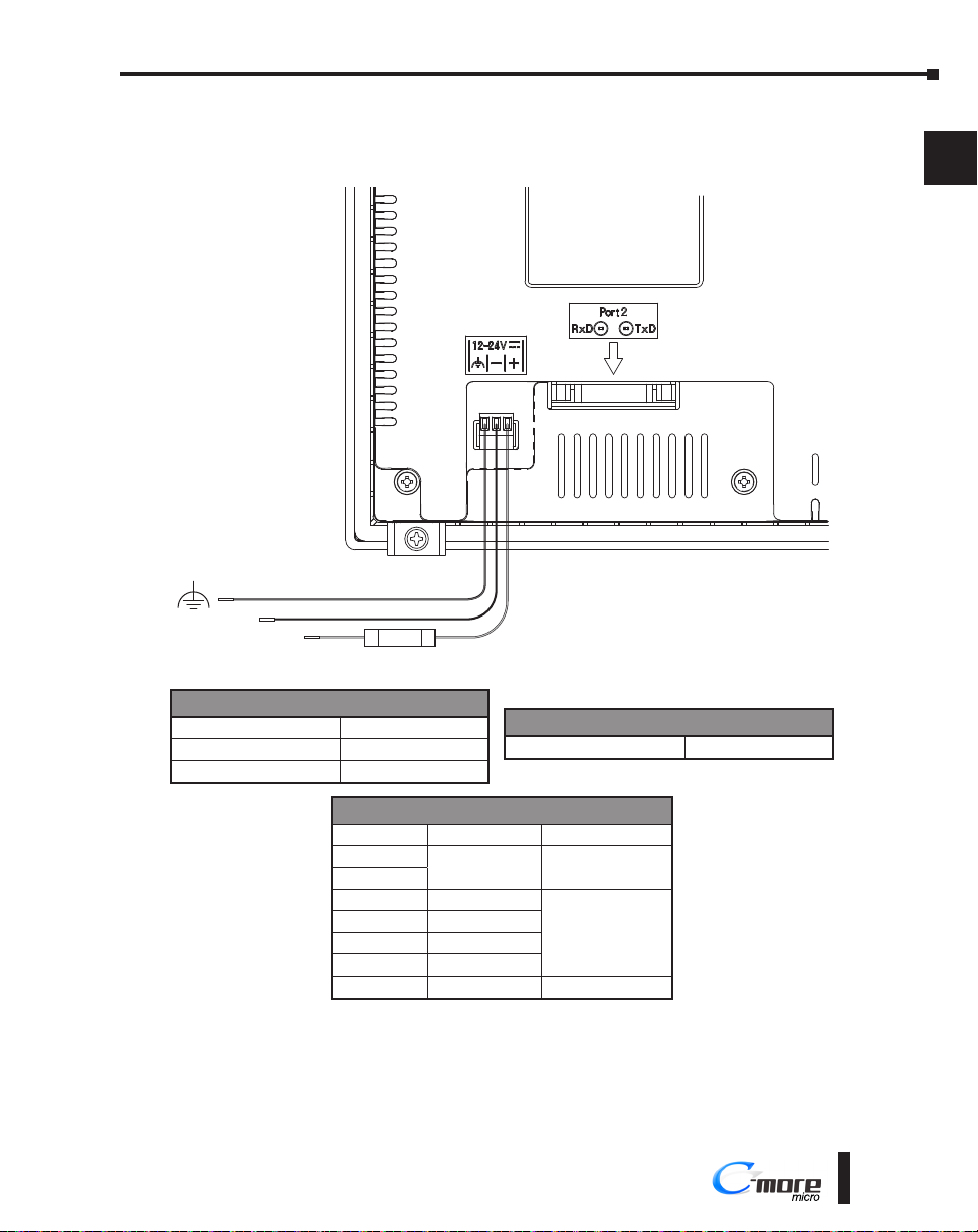
EA3-S3ML, EA3-T4CL, EA3-T6CL, EA3-T8CL and EA3-T10CL panels are powered by a
12-24 VDC class 2 power source .
Supply to Panel:
12–24 VDC
Equipment
Ground
–
+
2.5A
1
2
3
4
5
6
7
8
9
10
Required Wire Specification
Supported temperature Over 60 °C
Wire Material Copper
Wire Size 16 - 22 AWG
Recommended Power Supply
Part Number Power
EA3-S3ML-RN
EA3-S3ML-R
EA3-S3ML
EA3-T4CL
EA3-T6CL
EA3-T8CL
EA3-T10CL
Tightening Torque
Power supply wire connection 1.7 lb-in (0.2 Nm)
Power Supply
N/A N/A
3W
4W
7.5 W
8W
10W
PSL-24-010
PSC-24-015
®
11
12
13
14
A
B
C
D
1-15
Page 16
Chapter 1 - Getting Started
EA3-USER-M Hardware User Manual, 2nd Ed. Rev. L
Step 7 – Accessing the C-more Micro Panel Setup Screens
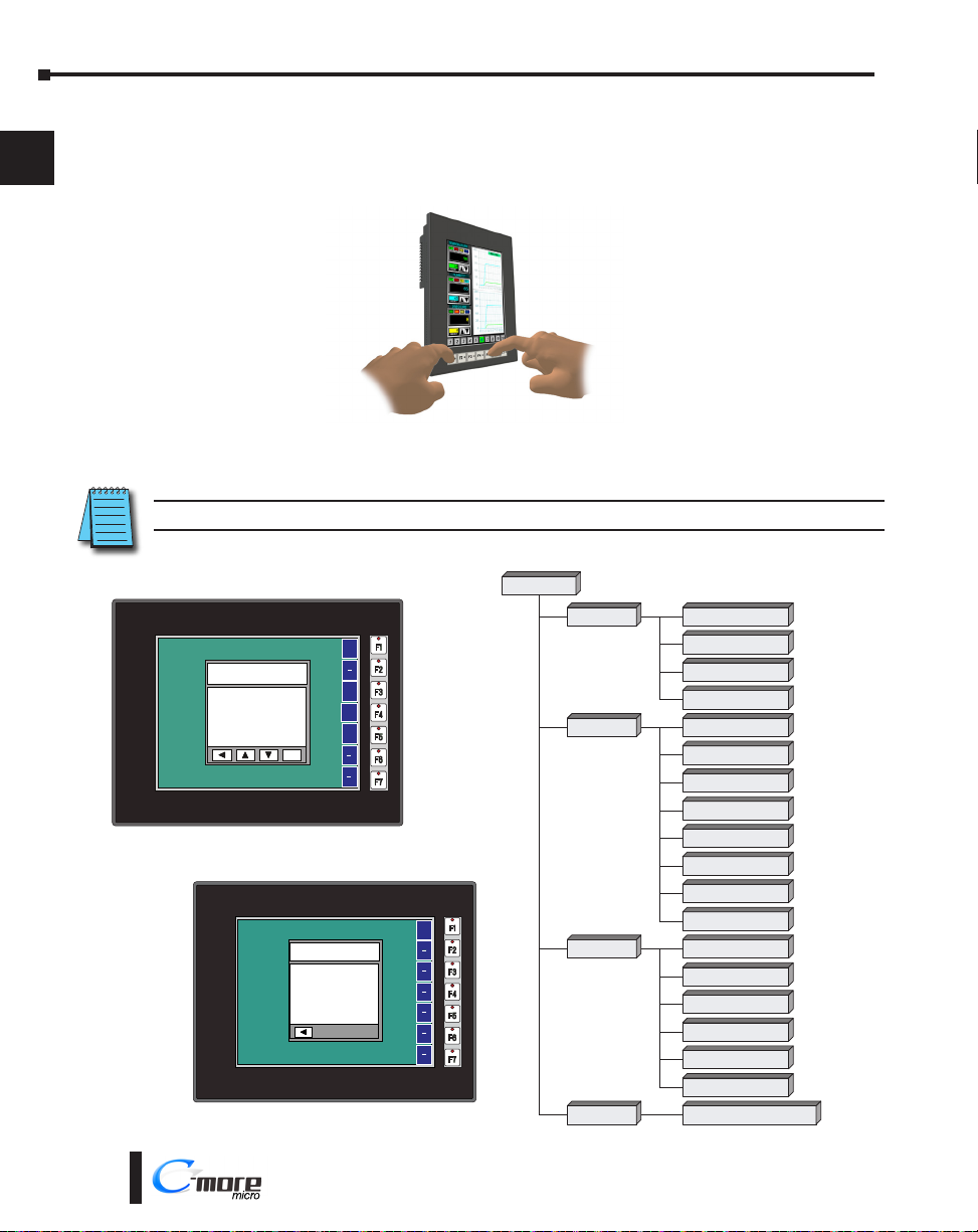
To access the Setup Menu of the panel’s setup screens on models with function keys, press
1
the the BAK [F1] and ENT [F5]function keys simultaneously for three (3) seconds. For EA3T4CL, touch the upper left corner of the screen for three seconds.
2
3
4
5
6
7
8
9
10
11
12
13
14
A
B
C
D
From the Setup Menu, information about the panel can be obtained, settings can be adjusted,
and panel functions can be tested.
NOTE: See Chapter 5: System Setup Screens for details on using the setup screen settings and functions.
Setup Menu
[pg. 5-5]
SETUP MENU
1. Information >
2. Setting >
3. Test Menu >
4. Exit >
ENT
MEMORY
Total:
31457200 Bytes
Usage:
0 Bytes
Free:
31457200 Bytes
1. Information
[pg. 5-6]
BAK
UP
DWN
ENT
BAK
2. Setting
[pg. 5-7]
3. Test Menu
[pg. 5-13]
4. Exit
[pg. 5-18]
1. Memory
[pg. 5-6]
2. Protocol
[pg. 5-6]
3. Extensions
[pg. 5-6]
4. Versions
[pg. 5-6]
1. Brightness
[pg. 5-7]
2. Touch / Key Beep
[pg. 5-8]
3 Calibration
[pg. 5-9]
4. Clear User Memory
[pg. 5-10]
5. Reset to Factory Default
[pg. 5-10]
6. Hourglass
[pg. 5-11]
7. Rotation
[pg. 5-12]
8. Ethernet
[pg. 5-12]
1. Serial Port1 – Loop Back Test
[pg. 5-14]
2.
Serial Port2 – Loop Back Test
[pg. 5-15]
3. PLC Enquiry Test
[pg. 5-16]
4. Buzzer Test
[pg. 5-16]
5. Touch Panel Test
[pg. 5-17]
6. Display Test
[pg. 5-17]
No[F1] / Yes[F5]
Do you want to exit from System Screen?
No[F1] / Yes[F5]
1-16
®
Page 17
Chapter 1 - Getting Started
EA3-USER-M Hardware User Manual, 2nd Ed. Rev. L
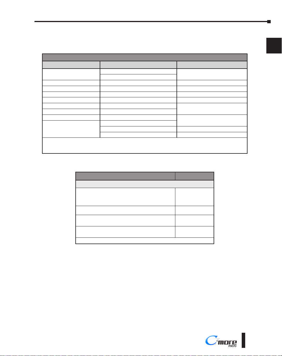
Step 8 – Choose C-more Micro Panel to PLC Protocol & Cables
Available PLC Protocols
PLC Drivers
Serial - port1 or port2 Serial - port2 only Ethernet*
AutomationDirect Productivity Series
AutomationDirect Do-more / BRX** Allen-Bradley PLC5 DF1 AutomationDirect Do-more / BRX Ethernet
AutomationDirect CLICK Allen-Bradley DH485 AutomationDirect CLICK Ethernet
AutomationDirect K-sequence GE SNPX (90/30, 90/70, Micro 90, VersaMax Micro) AutomationDirect ECOM Ethernet
AutomationDirect DirectNET Mitsubishi FX Modbus TCP/IP
AutomationDirect Modbus (master only) Mitsubishi Q & QnA
Modicon Modbus RTU (master only) Omron Host Link (C200 Adapter, C500)
Entivity Modbus RTU (master only) Omron FINS Serial (CJ1, CS1)
* Ethernet port is built in on EA3-S3ML and EA3-T4CL. Add an Ethernet port to EA3-T6CL, EA3-T8CL and EA3-T10CL with an optional
EA-ECOM module. Ethernet communications require external power supply.
** BX-P-SER2-RJ12 is required
Allen-Bradley DF1 Half Duplex
Allen-Bradley DF1 Full Duplex
Siemens PPI (S7-200 CPU)
AutomationDirect SOLO Temperature Controller
AutomationDirect GS Drives
AutomationDirect Productivity Series Ethernet
Allen-Bradley EtherNet / IP Client
(MicroLogix 1100/1400)
Allen-Bradley EtherNet / IP Client
(SLC5 / 05 / ENI Adapter)
Available Purchased Cables
Cable Description Cable Part No.
Cables used with RJ12 RS-232 serial Port1
AutomationDirect Productivity Series, Do-more / BRX*,
CLICK, Direct LOGIC PLC RJ-12 port, DL05, DL06, DL105,
DL205, D3-350, D4-450, D4-454 & H2-WinPLC (RS-232C).
3.66m (12ft) cable length
Direct LOGIC (VGA Style) 15-pin port, DL06, D2-250
(250-1), D2-260 (RS-232C). Use with D0-CBL cable.
Direct LOGIC PLC 15-pin D-sub port,
DL405 (RS-232C). Use with D0-CBL cable.
Direct LOGIC PLC RJ-11 port, D3-340 (RS-232C)
2m (6.56 ft) cable length
* BX-P-SER2-RJ12 is required
DV-1000CBL
FA-15HD
FA-CABKIT
OP-3CBL-1
1
2
3
4
5
6
7
8
9
10
11
12
13
Available Purchased Cables continued on the next page
®
14
A
B
C
D
1-17
Page 18
Chapter 1 - Getting Started
EA3-USER-M Hardware User Manual, 2nd Ed. Rev. L
Available Purchased Cables (cont’d)
1
2
3
4
5
6
7
8
9
10
11
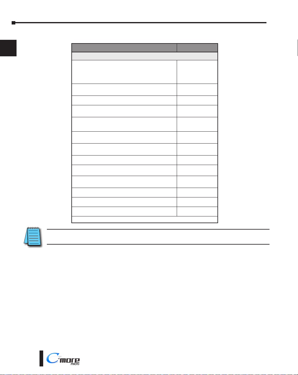
Cable Description Cable Part No.
Cables used with 15-pin RS-232/422/485 serial Port2
AutomationDirect Productivity Series, Do-more / BRX*,
CLICK, Direct LOGIC PLC RJ-12 port, DL05, DL06,
DL105, DL205, D3-350, D4-450, D4-454 & H2-WinPLC
(RS-232C)
3m (9.8 ft) cable length
Direct LOGIC (VGA Style) 15-pin port, DL06, D2-250 (250-
1), D2-260 (RS-232C) 3m (9.8 ft) cable length
Direct LOGIC PLC RJ-11 port, D3-340 (RS-232C)
3m (9.8 ft) cable length
Direct LOGIC DL405 PLC 15-pin D-sub port, DL405
(RS-232C) 3m (9.8 ft) cable length
Direct LOGIC PLC 25-pin D-sub port, DL405, D3-350,
DL305 DCU and all DCM’s (RS-232C)
3m (9.8 ft) cable length
Allen-Bradley MicroLogix 1000, 1100, 1200, 1400 & 1500
(RS-232C) 3m (9.8 ft) cable length
Allen-Bradley SLC 5-03/04/05, ControlLogix, CompactLogix,
FlexLogix DF1 port (RS-232C) 3m (9.8 ft) cable length
Allen-Bradley PLC-5 DF1 port (RS-232C)
3m (9.8 ft) cable length
Allen-Bradley SLC 5-01/02/03 DH485 port
3m (9.8 ft) cable length
GE 90/30, 90/70, Micro 90, Versamax Micro (Port2) 15-pin
D-sub port (RS-422A) 3m (9.8 ft) cable length
MITSUBISHI FX Series 25-pin port (RS-422A)
3m (9.8 ft) cable length
MITSUBISHI FX Series 8-pin mini-DIN (RS-422A)
3m (9.8 ft) cable length
OMRON Host Link (C200 Adapter, C500) (RS-232C)
3m (9.8 ft) cable length
* BX-P-SER2-RJ12 is required
EA-2CBL
EA-2CBL-1
EA-3CBL
EA-4CBL-1
EA-4CBL-2
EA-MLOGIX-CBL
EA-SLC-232-CBL
EA-PLC5-232-CBL
EA-DH485-CBL
EA-90-30-CBL
EA-MITSU-CBL
EA-MITSU-CBL-1
EA-OMRON-CBL
12
NOTE: See Chapter 6: PLC Communications for a detailed chart of PLC compatibility & cable connections.
Chapter 6 includes wiring diagrams for end user construction of certain cables.
13
14
A
B
C
D
1-18
®
Page 19
Chapter 1 - Getting Started
EA3-USER-M Hardware User Manual, 2nd Ed. Rev. L
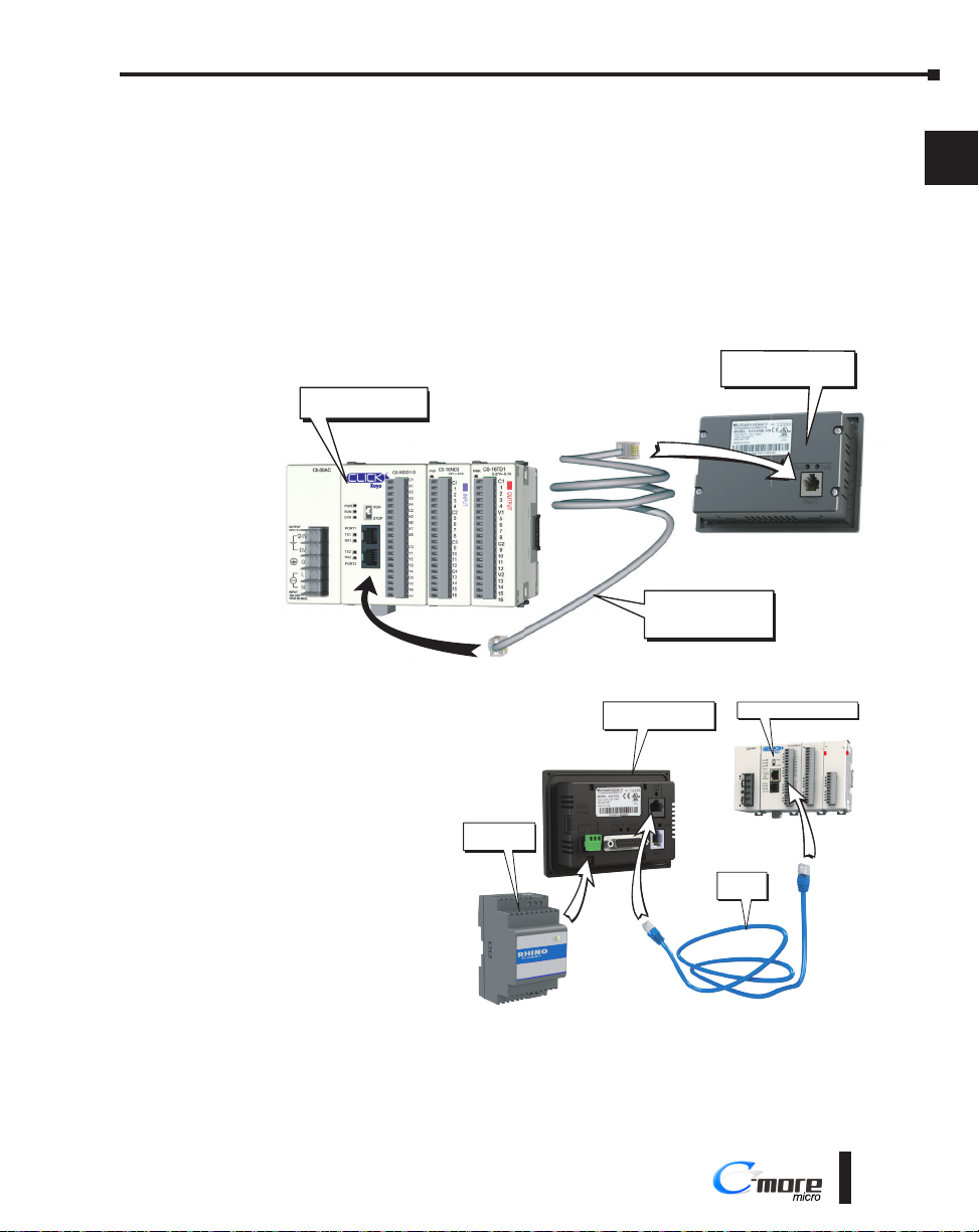
Step 9 – Connect C-more Micro Panel to PLC
Connect the serial communications cable between the C-more Micro panel and the PLC. The
panel can be connected to the PLC via the panel’s built-in RJ12 serial communications port
(RS-232) or depending on model, the 15-pin serial communications port with either RS-232,
RS-422 or RS-485 communications. Adding the optional EA-ECOM module to the EA3 6,8
and 10-inch models allows communications via an Ethernet connection. An Ethernet port is
built-in to the EA3-S3ML and EA3-T4CL.
Example of panel’s Port 1
connected to a CLICK PLC
EA3-S3ML-R(N)
C-more Micro Panel
CLICK PLC
Port 1
1
2
3
4
5
6
7
8
Port 2
Example of EA3-T4CL
Ethernet Port connected to
a CLICK PLC with Ethernet
PSC-24-030
Power Supply
DV-1000CBL
serial cable
C-more EA3-T4CL
Micro Panel
CLICK Ethernet PLC
C0-00AC
OUTPUT
24V 0.5A
24V
0V
G
L
N
INPUT
100-240V
15VA 50-60Hz
Port 1
Ethernet
Cable
9
10
11
C0-08TD1
PWR
C0-16TD1
PWR
3.3-27V 0.3A
5-27V 0.1A
C1
1
OUTPUT
OUTPUT
2
3
4
V1
5
6
7
C1
8
1
C2
2
9
3
10
4
11
C2
12
5
V2
13
6
14
7
15
8
16
+V
12
13
14
A
B
C
D
®
1-19
Page 20
Chapter 1 - Getting Started
EA3-USER-M Hardware User Manual, 2nd Ed. Rev. L
1
2
PSC-24-030
Power Supply
C-more
Micro Panel
CLICK PLC
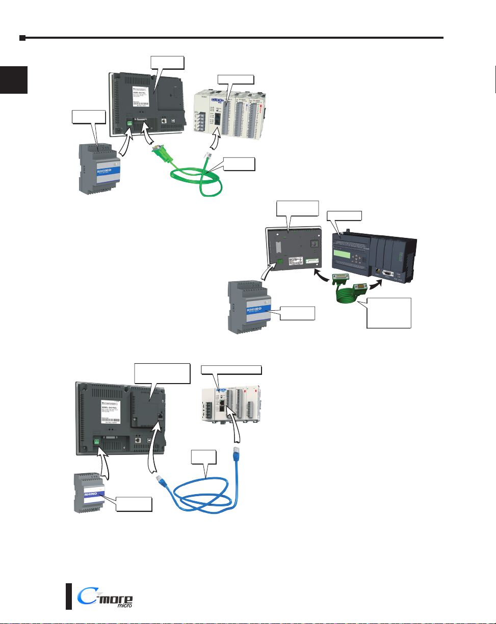
Example of panel’s Port 2
connected to a CLICK PLC
3
4
5
6
7
8
9
10
11
12
13
14
A
Port 2
Example of panel’s Port 2
connected to a DL06 PLC
C-more EA3 Series
Micro Panel with
EA-ECOM module
Ethernet
Cable
CLICK Ethernet PLC
OUTPUT
24V 0.5A
24V
0V
G
L
N
INPUT
100-240V
15VA 50-60Hz
C0-00AC
Port 2
EA-2CBL
serial cable
Port 1
C-more
Micro Panel
PSC-24-030
Power Supply
C0-08TD1
PWR
C0-16TD1
PWR
3.3-27V 0.3A
5-27V 0.1A
C1
1
OUTPUT
OUTPUT
2
3
4
V1
5
6
7
C1
8
1
C2
2
9
3
10
4
11
C2
12
5
V2
13
6
14
15
16
Example of optional EA-ECOM
7
8
+V
DL-06 PLC
Port
2
Port
2
C-more to
Direct LOGIC
VGA 15-pin port
serial cable
p/n EA-2CBL-1
module connected to a CLICK
PLC with Ethernet.
B
PSC-24-030
Power Supply
C
D
1-20
®
 Loading...