

Page 1

Chapter
Chapter
BRX Do-moRe!
Chapter
SeRial CommuniCationS
12
12
12
In This Chapter...
Overview ..................................................................................................................................................... 12-2
General Concepts .................................................................................................................................... 12-2
Terminology ............................................................................................................................................. 12-3
Troubleshooting Serial Communications ................................................................................................... 12-4
Communications Design ............................................................................................................................ 12-5
Sequencing Communications ................................................................................................................ 12-5
USB Communications ................................................................................................................................. 12-9
Serial Communications ............................................................................................................................... 12-9
General Serial Specifications .................................................................................................................... 12-10
RS-232 .................................................................................................................................................... 12-10
RS-422 .................................................................................................................................................... 12-11
RS-485 .................................................................................................................................................... 12-12
MPU Built-in Serial Port Specifications ................................................................................................. 12-13
POM Specifications ................................................................................................................................ 12-14
Serial Expansion Modules Specifications .............................................................................................. 12-16
Serial Port Setup and Programming ........................................................................................................ 12-17
Serial Port Settings ................................................................................................................................ 12-17
Serial Protocols ......................................................................................................................................... 12-20
Do-more! Protocol ................................................................................................................................. 12-20
Modbus RTU .......................................................................................................................................... 12-20
Modbus RTU Server (Slave) .................................................................................................................. 12-20
Modbus RTU Client (Master) ................................................................................................................ 12-21
K-Sequence Server (Slave) .................................................................................................................... 12-26
ASCII....................................................................................................................................................... 12-27
DMX512 (Master & Slave) .................................................................................................................... 12-32
Page 2

Chapter 12: BRX Do-more! Serial Communications
Overview
The purpose of this chapter is to help the user gain an understanding of the serial communications capabilities
of the BRX platform. The BRX platform features the Do-more! DM1 technology which has a very robust
communications system allowing the programmer to accomplish many tasks that can prove difficult with
other PLCs. Every BRX MPU has a built-in RS232/485 (software-selectable) serial port. Pluggable Option
Modules (POM) and Expansion modules are also available that will add additional RS-232 and RS-485 port
configurations.
The BRX platform provides a wide variety of serial protocols to choose from and is capable of serial
communications to a wide variety of field devices such as HMIs, SCADA systems, PLCs, barcode readers
and scales, to name a few.
The available protocols are:
• Modbus RTU protocol: one of the most popular and widely used protocols in the industrial
automation community.
• Do-more! protocol: can access the entire BRX memory structure and can utilize a security account
to protect the data. Some HMIs and SCADA software such as C-more and C-more Micro, can take
advantage of this enhanced security while keeping data transmission integrity intact.
• K-sequence protocol: is typically used to communicate with DirectLOGIC PLC systems.
• ASCII: although technically not a protocol, it is supported to communicate with devices such as
scales, barcode readers and other simple devices.
• DMX512 protocol: stage lighting control protocol allows the BRX platform to easily send and receive
commands to most DMX512 devices and controllers.
• Custom protocol: if there is a need for a protocol that is not available, and the user has a thorough
working knowledge of the protocol, it is possible for a user to use the available raw commands to
write a custom protocol the DM1 technology can execute.
The following sections of this chapter as well as the software help file will be of significant use to you when
connecting and communicating with the various protocols needed for these types of devices.
General Concepts
As a security feature, when communicating with Modbus RTU or K-sequence the controller does not allow
external devices that communicate with the controller to have direct access to the controller’s internal memory
and I/O. These protocols will be serviced through reserved memory blocks designated for that protocol. This
is setup to allow the programmer to pass data externally when using third party devices while maintaining a
secure environment. This is discussed in more detail in each protocol section later in this chapter.
12-2
BRX User Manual, 4th Edition, Rev. F
Page 3
Chapter 12: BRX Do-more! Serial Communications
Terminology
During the course of this chapter we will use terminology and phrases that are specific to a Protocol or
Physical Medium the user should understand. By way of explanation we have included some common terms
and definitions in this section. Definitions and explanations of specific parameters particular to each Protocol
will be discussed later in this chapter.
Physical Medium – Wires, radios, cellular service, or satellite link. The physical method (hardware) on which
the data is being transmitted or received. The physical medium contains no data information. Examples of a
physical medium are: RS-232, RS-485 and Ethernet 10/100 Base T.
Protocol – A Protocol is the specification for the formatting of the data (bits, bytes and words) being
transmitted through the physical medium. Examples of some common industry protocols are: Modbus RTU
and K-Sequence.
One way to think of the Physical Medium and the Protocol is to liken them to placing a phone call. The phone
call is being placed over wires, cellular service or even perhaps a satellite link. This is the physical medium.
Now if the call was to China, you would say “Hello” in English. If the person on the other end understands
English, they will respond with “Hello”. If the person on the other end only understands Mandarin Chinese
they might respond “Ni Hao”. If you do not understand Chinese, you will be confused as to what they are
saying. This is the same for a Protocol. If your PLC uses Modbus RTU and you try to talk to a PLC that only
understands K-Sequence, then you will not be able to communicate with it. The Protocols must match in
order to communicate.
Client (Master) – A Client is a Master device that requests data from a Server (Slave) device. The Client
(Master) device initiates communications with a Server (Slave) device.
Server (Slave) – A Server is a Slave device that responds to a request from a Client (Master) device. The
Server (Slave) device listens/replies to requests made by a Client (Master).
Field Device – A device external to the BRX MPU.
NOTE: Software dialog windows and other documentation may interchangeably use the terms Client/Server or
Master/Slave when referring to requesting/responding devices in Ethernet or Serial communications. In this chapter,
with regards to Serial communications, we will use the term Client to refer to a requesting device and Server to
refer to a responding device.
BRX User Manual, 4th Edition, Rev. F
12-3
Page 4

Chapter 12: BRX Do-more! Serial Communications
Troubleshooting Serial Communications
Troubleshooting communications can seem frustrating to the novice because you cannot see what is
happening in real time. However, most communications troubleshooting is fairly straight forward if you take
the right steps. Below are some recommendations for how to go about troubleshooting when a device does
not communicate.
1. Make sure the baud rate, parity, stop bits, end bits, RTS/CTS control and other parameters match
both the sending and receiving devices. With RS-485 make sure each device has a unique ID number.
2. Make sure the wiring is the right choice for the communications standard that you are using. Having
the right wire with the right impedance and capacitance characteristics is very important. Using
the wrong type wire will nearly certainly cause the link to fail or at the very least be very noisy and
troublesome.
3. Make sure that the wiring pinouts are correct between the devices. For RS-232, RX and TX must
be swapped for DTE devices. Ground must be used for RS-232. For RS-485, Plus should go to Plus
and Minus to Minus.
4. RS-232 is a ground referenced signal. This means that having a good common ground connection
between the devices is extremely important. If the devices are not at the same ground potential, they
will not communicate properly and can even cause damage to the connected devices. Both devices
should be grounded at the same potential source.
5. RS-232 is a one to one wiring standard. It cannot be multi-dropped without special adapters. For
multi-drop (slave) arrangements, RS-485 is the preferred method.
6. For RS-485 links one of the most common issues is that the plus and minus wires simply need to be
swapped. These may be labeled differently depending on the manufacturer, but the principle is the
same. RS-485 usually has a ground wire, but it is not quite as important as with RS-232 since RS-485
is a differential signal that is not ground referenced.
7. Termination resistors may be required to prevent data reflections from the ends of the cable. These
resistors should match the cable impedance as closely as possible. For shorter runs of a few feet of
cable, the resistors may cause issues and it should be tested to see if they are needed or not.
8. Make sure that the protocols match between the sending and receiving devices.
9. If available RX and TX lights should be flashing or steady if data is being transferred. If only one light
is on or if no lights are on, then it is likely not working.
10. The last tip is to start simple. Start with a simple program that uses a single read instruction to a
single address that holds a known, non-zero value. Once you get this working, start to expand the
capabilities. Don’t start off your troubleshooting journey with a full program of reads and writes using
radios and long wire distances. Keep it simple. Start small and grow.
12-4
BRX User Manual, 4th Edition, Rev. F
Page 5
Communications Design
The BRX platform features the Do-more! DM1 technology which has a very robust communications system
allowing the programmer to accomplish many tasks that can prove difficult with other PLC’s. The DM1
technology manages the asynchronous actions of communications in the background without taking a huge
hit on the PLC scan time.
Sequencing Communications
The easy way
In many PLC’s the programmer must manage the communications sequencing. This can be frustrating and
time consuming to get the communications working correctly especially when you have multiple requests
to handle. The DM1 technology eliminates this frustration and will simply manage each Comm request in
the order that the program initiates a request. You no longer must write code to sequence and manage each
request. For some applications this is enough to do what the programmer needs to accomplish.
More advanced sequencing – State Machines
State machines have been used to sequence communication sequences for a very long time. The reason for
this is that communications by definition consists of always being in a particular state and transitioning to a
different state based on some action. This is all that there is to state machine programming; do an action and
wait for something to happen, then move to a different action.
Chapter 12: BRX Do-more! Serial Communications
Do-more! supports state machine programming. This is accomplished by the use of Stages. Stage programming
has been around a long time and Do-more! PLC’s take full advantage of Stage programming. For more
information on Stage Programming see Do-more! Designer Help topic DMD0502.
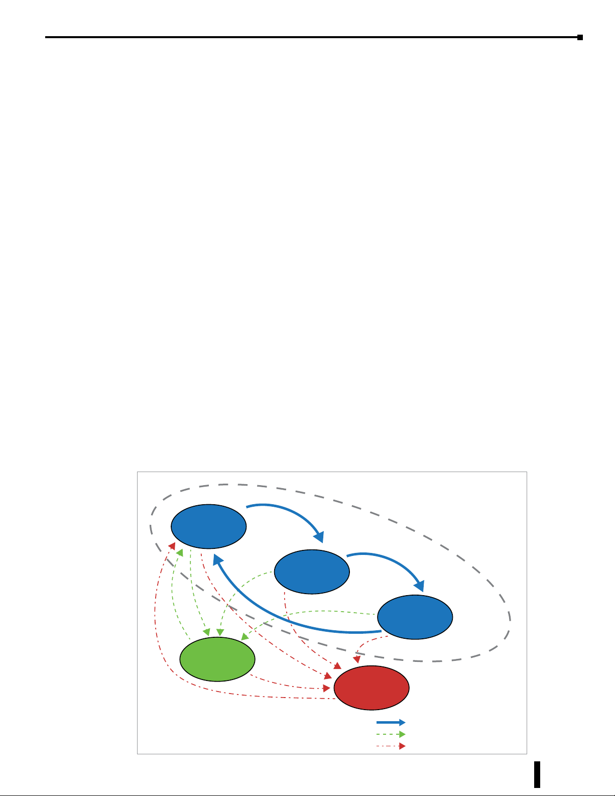
For our example on State Machine programming using Stages consider talking to a variable speed motor
controller. What is there that you will be doing? By drawing out the conditions, you can see that there are
definite states that the communications to the motor controller will be going through.
Main Loop
Read #1
Controller Status
Read #2
Speed
Read #3
Amps
Write #1
Start
Communications Exception Functions
BRX User Manual, 4th Edition, Rev. F
Error
Normal Communications Flow
Write Exception
Error Condition
12-5
Page 6
Chapter 12: BRX Do-more! Serial Communications
Sequencing Communications, continued
In this example we can see that we have three reads from the device and one write condition. We can also see
that we need an error handling routine. That’s all there is to it. It looks fairly simple when we draw it out in
this manner. The beauty of drawing a State Machine out with a flow chart is that it transitions in nearly the
exact same manner to ladder logic.
Main loop:
Read #1 – Read the Controller status word. This might consist of whether the drive is running, jogging,
in error, etc.
Read #2 – Read the Controller speed. How fast is it running?
Read #3 – Read the amp draw. Is it within limits?
Main loop end
Things that happen occasionally:
Write #1 – Start the Controller running.
Error – Something bad happened to the communications. What do we need to do to flag this as a
problem?
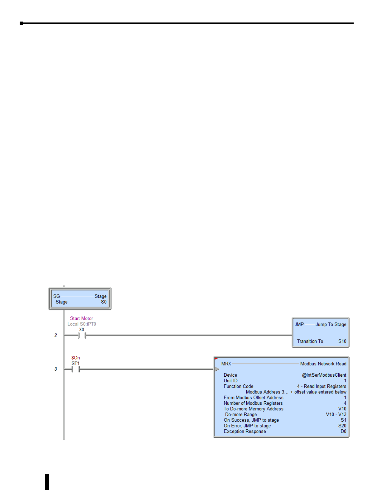
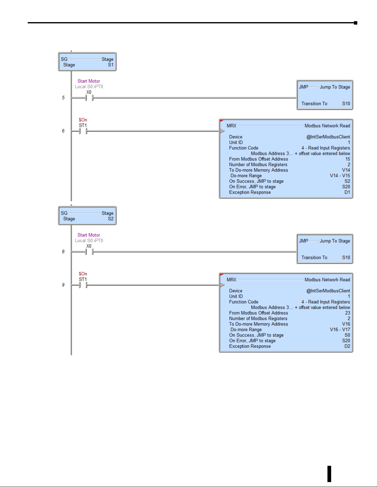
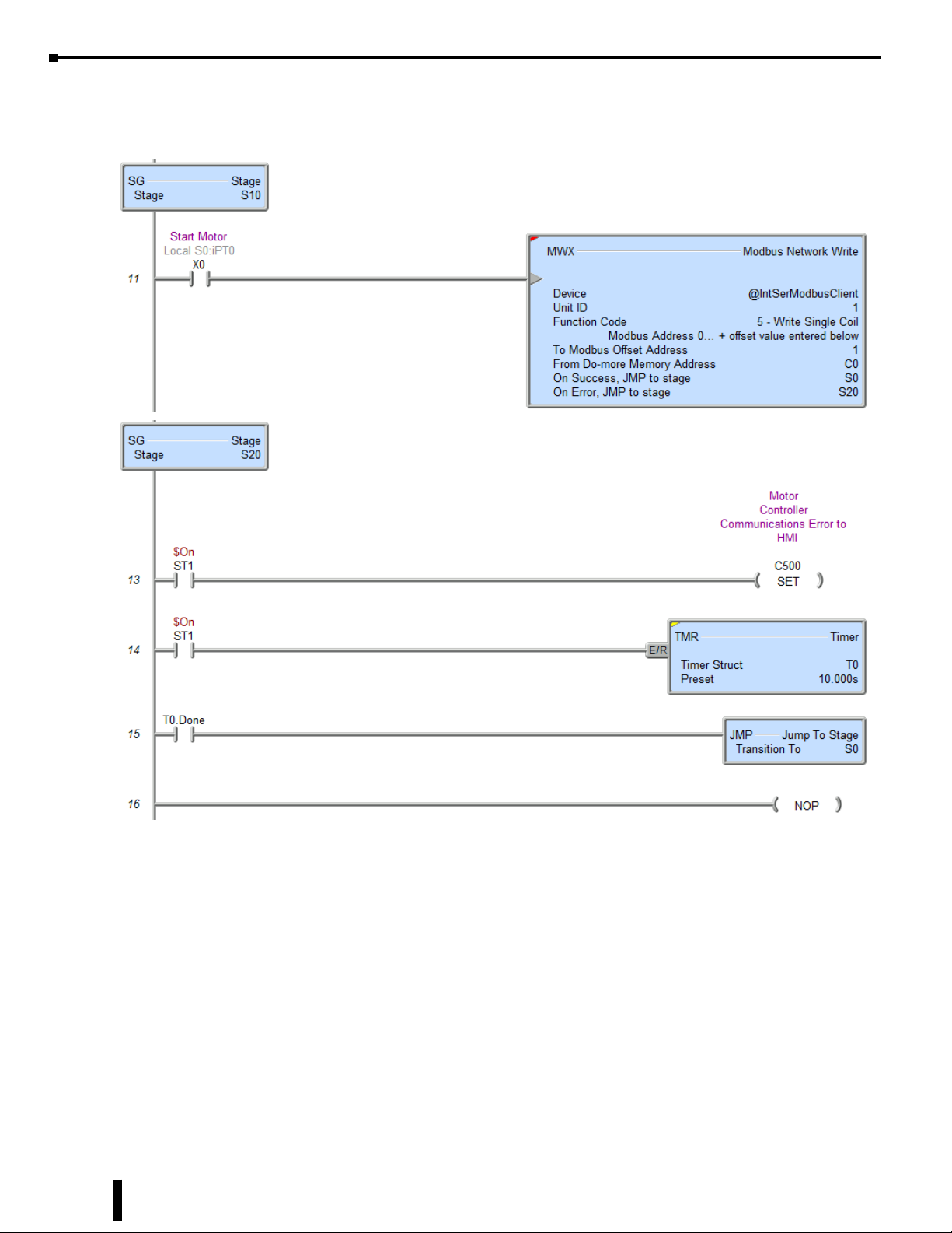
An implementation of this State Machine in ladder logic is shown below. Since the Do-more! Communication
instructions have built in transitioning between Stages based on Success or Error, this eliminates a lot of
programming. To accomplish the diagram the only manual transitioning that needs to occur is for the Write
to start the motor controller.
While this example is somewhat incomplete in that it does not have provisions for stopping the drive or
other potential needs, it does serve to show how State Programming can help to make transitioning between
communications states relatively easy in the Do-more! Controller.
Main loop:
Read #1
12-6
(continued on next page)
BRX User Manual, 4th Edition, Rev. F
Page 7
Sequencing Communications, continued
(continued from previous page)
Read #2
Chapter 12: BRX Do-more! Serial Communications
Main loop end
Read #3
(continued on next page)
BRX User Manual, 4th Edition, Rev. F
12-7
Page 8
Chapter 12: BRX Do-more! Serial Communications
Sequencing Communications, continued
(continued from previous page)
Things that happen occasionally:
Write #1
Error Handling
12-8
BRX User Manual, 4th Edition, Rev. F
Page 9
USB Communications
The POM slot USB port is useful for programming and monitoring the BRX Do-more! MPU. It is compatible
with Desktop PCs and Laptops utilizing USB 2.0 or higher, communicating through USB Type A to USB
Type B cable. It does not support connections to other USB devices such as printers.
The POM slot USB port relies on drivers included with Windows, so there are no drivers to download. It
truly is plug and play.
Serial Communications
There are multiple options when doing serial communications with a BRX PLC. The MPU has a built in
serial port that can do RS-232 and RS-485 communications. The BRX POM modules have several options
from which you can pick the style of serial port that you might want. The BRX serial expansion modules
have 4 serial ports that can do RS-232, RS-422 or RS-485 communications. If you need more ports, just add
more modules.
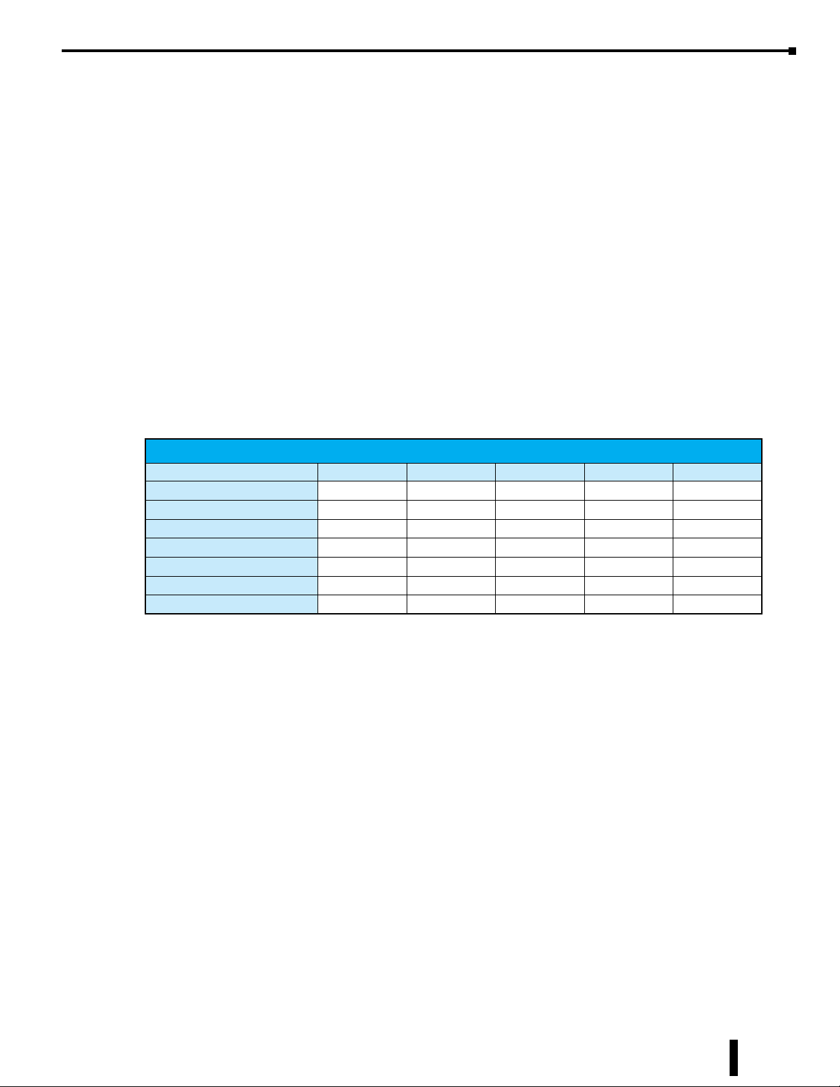
See the table below for a matrix of what protocols are supported by the different communications options.
Chapter 12: BRX Do-more! Serial Communications
Supported Communications Protocols
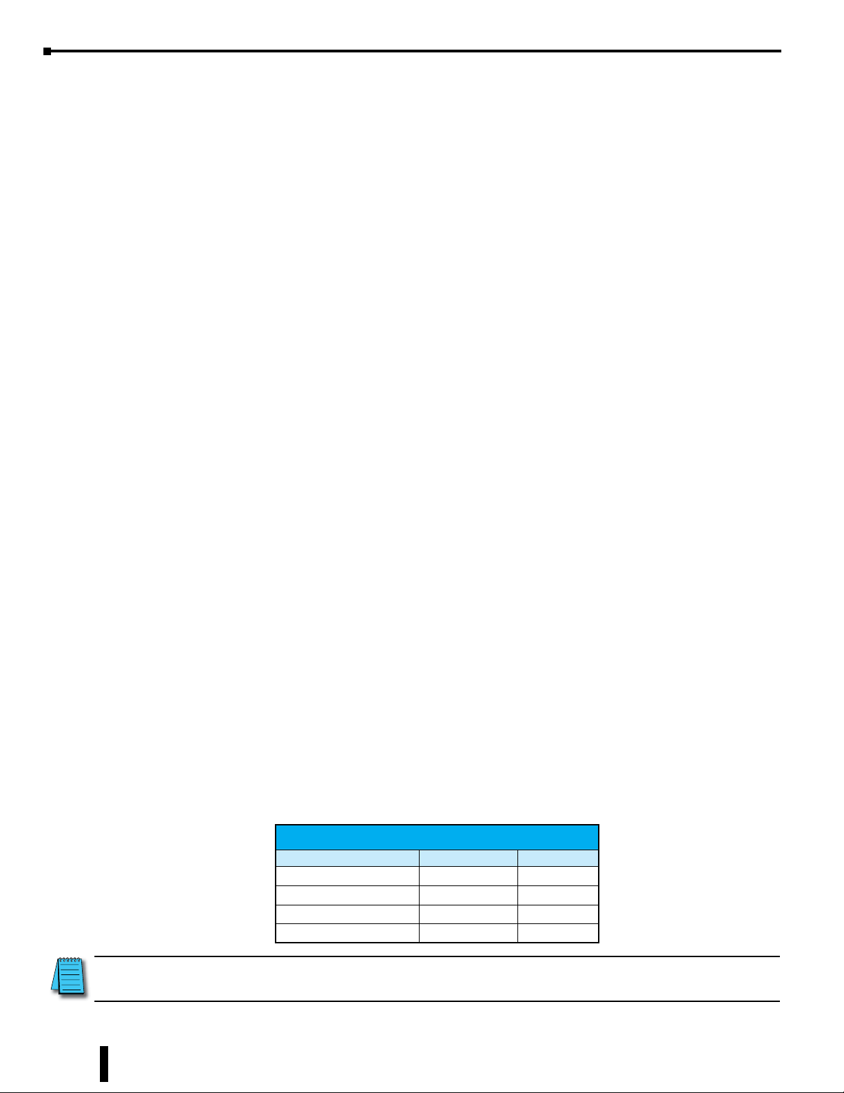
Protocol Onboard Serial POMs BX-SERIO BX-SERIO-2 BX-SERIO-4
Do-more Protocol (Slave) X X X X X
Modbus RTU (Slave) X X X X X
Modbus RTU (Master) X X X X X
K-Sequence (Slave) X X X X X
ASCII X X X X X
DMX512 (Controller) X
DMX512 (Slave) X
BRX User Manual, 4th Edition, Rev. F
12-9
Page 10
Chapter 12: BRX Do-more! Serial Communications
1 0V
2 RXD
3 TXD
0V 1
RXD 2
TXD 3
DTE DTE
MPU
Device
General Serial Specifications
RS-232
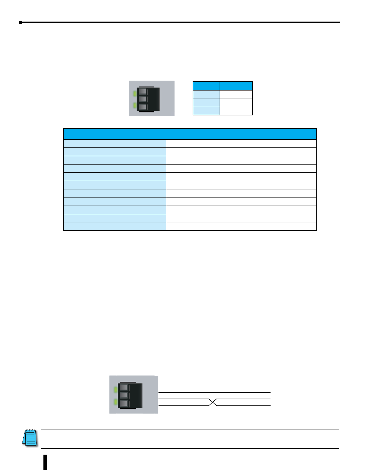
RS-232 is a single point wiring standard that can be used to connect external devices to the PLC.
RS-232/485
TX
RX
GND
RX/D-
TX/D+
Pinout RS-232
1 GND
2 RX
3 TX
General RS-232 Specifications
Data Rates 1200, 2400, 4800, 9600, 19200, 38400, 57600, and 115200
Default Settings RS-232, 115200 bps, No Parity, 8 Data Bits, 1 Stop Bit, Station #1
Port Status LED Green LED is illuminated when active for TXD and RXD
Port Type 3-pin terminal strip 3.5mm pitch
RS-232 TXD RS-232 Transmit output
RS-232 RXD RS-232 Receive input
RS-232 GND Logic ground
RS-232 Maximum Output Load (TXD/RTS) 3kΩ, 1000 pf
RS-232 Minimum Output Voltage Swing ±5VDC
RS-232 Output Short Circuit Protection ±15mA
Maximum Distance 6 meters (20 foot) recommended maximum
The manner in which external devices are wired to the BRX serial port depend on whether the device is
considered to be Data Terminal Equipment (DTE) or Data Communications Equipment (DCE). The BRX
serial port is considered a DTE device. Most Modbus or ASCII devices being connected to the BRX serial
port will also be considered a DTE device and will need to swap TX and RX (as shown below), but you
should always consult the documentation of that device to verify.
12-10
If a device such as a Modem, which is a DCE device, is placed between the BRX serial port and another
Modbus or ASCII device it will most likely require connecting the signals straight across (TX to TX and
RX to RX). Again, this can differ from manufacturer to manufacturer so always consult the documentation
before wiring the devices together.
RS-232 is a ground referenced signal and as such it is susceptible to noise and ground differentials which may
make it unsuitable for use in some circumstances.
The wiring for RS-232 is shown below. Please note that there are no connections for RTS (Ready To Send),
CTS (Clear To Send) or for port powered devices (+5VDC).
RS-232/485
TX
RX
NOTE: Recommended distance between RS-232 devices is less than 6 meters (20 feet) in industrial environments.
GND
RX/D-
TX/D+
For longer distances, please consider using RS-485 or Ethernet.
BRX User Manual, 4th Edition, Rev. F
DTE DTE
1 GND
2 RX
3 TX
BRX
GND (0V)
RX
TX
Field
Page 11
Chapter 12: BRX Do-more! Serial Communications
RS-422
General Serial Specifications, continued
RS-422
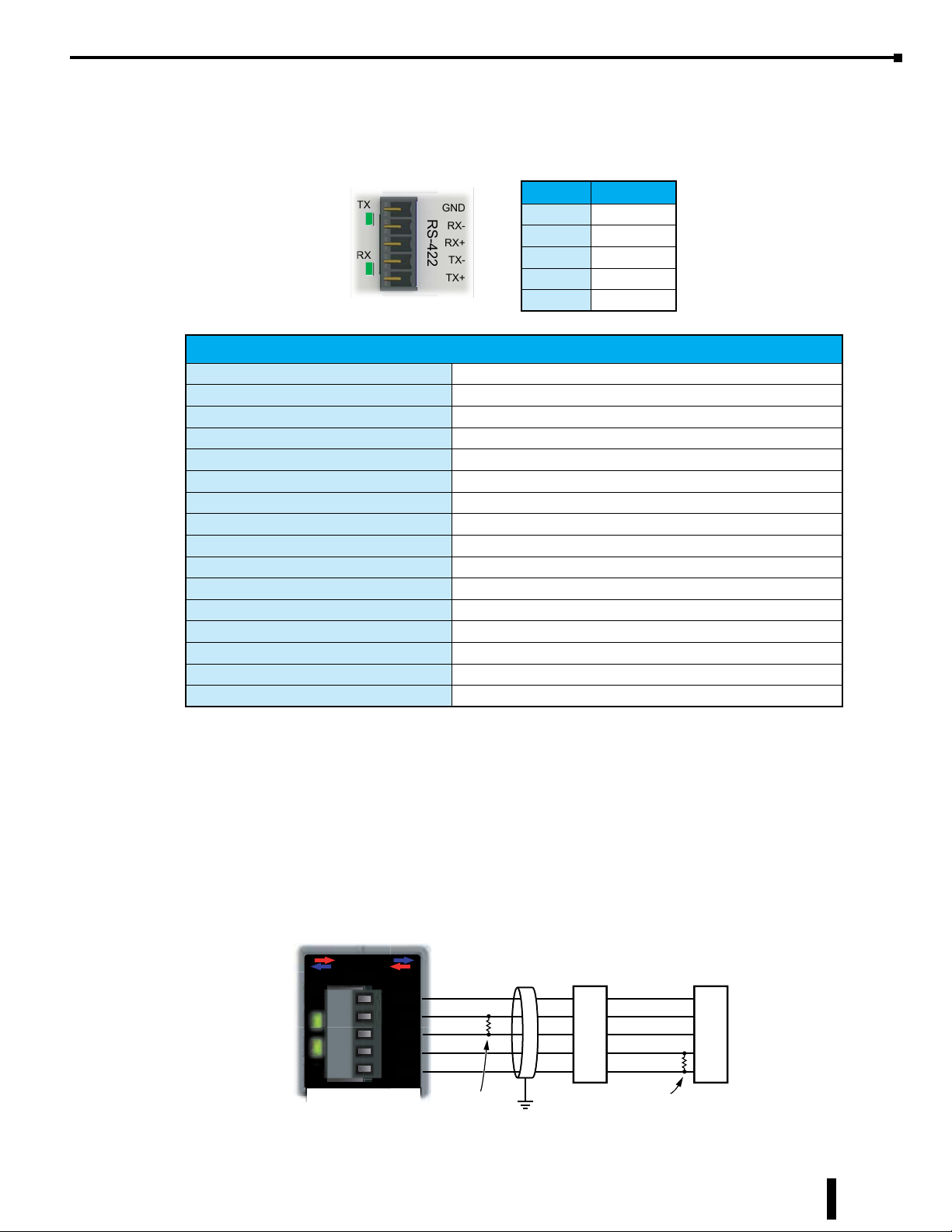
RS-422 is a multi-point wiring standard that can be used to connect external devices to the PLC.
TX
RX
GND
RS-422
RX-
RX+
TX-
TX+
Pinout RS-422
1 GND
2 RX-
3 RX+
4 TX-
5 TX+
General RS-422 Specifications
Data Rates 1200, 2400, 4800, 9600, 19200, 38400, 57600, and 115200
Default Settings RS-422, 115200 bps, No Parity, 8 Data Bits, 1 Stop Bit, Station #1
Port Status LED Green LED is illuminated when active for TXD and RXD
Port Type 5-pin terminal strip 3.5mm pitch
RS-422 Station Addresses 1-247
RS-422 TXD-/RXD- RS-422 transceiver low
RS-422 TXD+/RXD+ RS-422 transceiver high
RS-422 GND Logic ground
RS-422 Input Impedance 96kΩ
RS-422 Maximum Load 50 transceivers, 19kΩ each, 120Ω termination
RS-422 Output Short Circuit Protection ±250mA, thermal shut-down protection
RS-422 Minimum Differential Output Voltage 2.0 VDC with 54Ω load
RS-422 Maximum Common Mode Voltage -7.5-12.5 VDC
RS-422 Fail Safe Inputs Logic high input state if inputs are unconnected
RS-422 Electrostatic Discharge Protection ±15KV human body, ±6KV contact discharge per IEC1000-4-2
Maximum Distance 1000 meters (3280 feet)
The RS-422 port is useful for connecting multiple receivers to one transmitter on one network and/or
connecting devices to the BRX serial port at much longer distances than RS-232. The RS-422 standard
supports distances of up to 1000 meters. The RS-422 serial port can support up to 50 devices, depending on
the load of each device (assuming a 19kΩ load for each device).
RS-422 utilizes a differential signal which makes it much more immune to noise and grounding issues than
RS-232 and is therefore a much better choice when available for communications.
The wiring for RS-422 is shown below.
OIOIRESRES
RRS-422S-422
AA
TXXXT
RXRXX
BX-SERIO-4
GGNDND
RX
RX-
RXRX++
TX-TX-
1 Signal GND
2 RX-
-
3 RX+
4 TX5 TX+
+X+XTT
Field Device
120Ω Resistor
Termination
User-supplied
Slave 1
GND
TX-
TX+
RX-
RX+
Field Device
120Ω Resistor
Termination
User-supplied
Last Slave
GND
TX-
TX+
RX-
RX+
BRX User Manual, 4th Edition, Rev. F
12-11
Page 12
Chapter 12: BRX Do-more! Serial Communications
1 0V
2 RXD
3 TXD
0V 1
RXD 2
TXD 3
DTE DTE
General Serial Specifications, continued
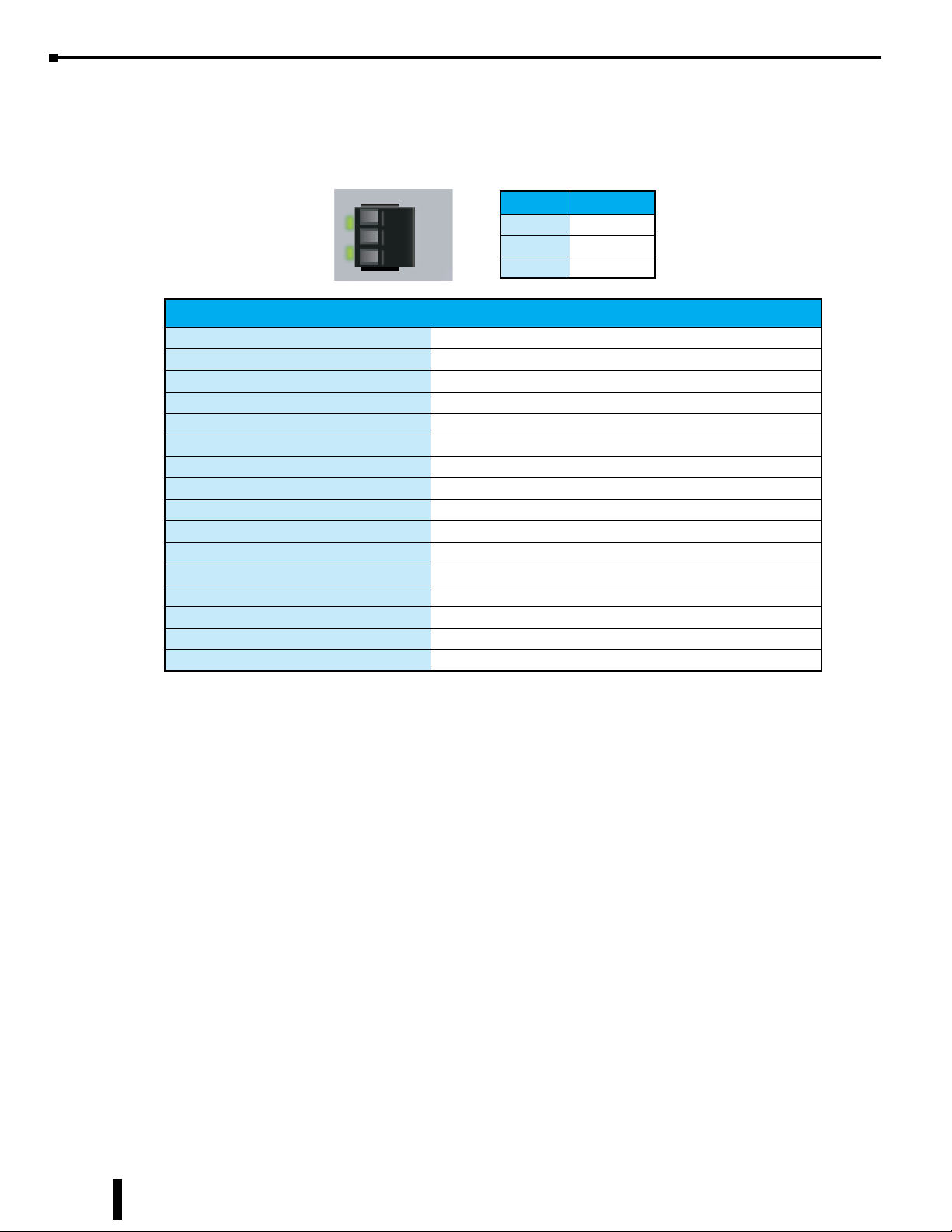
RS-485
RS-485 is a multi-point wiring standard that can be used to connect external devices to the BRX serial port.
RS-232/485
TX
RX
GND
RX/D-
TX/D+
Pinout RS-485
1 GND
2 D-
3 D+
General RS-485 Specifications
Data Rates 1200, 2400, 4800, 9600, 19200, 38400, 57600, and 115200
Default Settings RS-232, 115200 bps, No Parity, 8 Data Bits, 1 Stop Bit, Station #1
Port Status LED Green LED is illuminated when active for TXD and RXD
Port Type 3-pin terminal strip 3.5mm pitch
RS-485 Station Addresses 1-247
RS-485 TXD-/RXD- RS-485 transceiver low
RS-485 GND Logic ground
RS-485 Input Impedance 19kΩ
RS-485 Maximum Load 50 transceivers, 19kΩ each, 120Ω termination
RS-485 Output Short Circuit Protection ±250mA, thermal shut-down protection
RS-485 Minimum Differential Output Voltage 1.5 VDC with 60Ω load
RS-485 Maximum Common Mode Voltage -7.5-12.5 VDC
RS-485 Fail Safe Inputs Logic high input state if inputs are unconnected
RS-485 Electrostatic Discharge Protection ±8KV per IEC1000-4-2
RS-485 Electrical Fast Transient Protection ±2KV per IEC1000-4-4
Maximum Distance 1000 meters (3280 feet)
The RS-485 port is useful for connecting multiple devices on one network and/or connecting devices to the
BRX serial port at much longer distances than RS-232. The RS-485 standard supports distances of up to
1000 meters without requiring a repeater. The distance can be increased by placing an RS-485 repeater on
the network, if necessary. The BRX serial port in the RS-485 mode can support up to 50 devices, depending
on the load of each device (assuming a 19kΩ load for each device).
RS-485 utilizes a differential signal which makes it much more immune to noise and grounding issues than
RS-232 and is therefore a much better choice when available for communications.
This port only supports RS-485, 2-wire connections. For 4-wire RS-485 or RS-422, a converter, such as an
FA-ISOCON must be used.
12-12
BRX User Manual, 4th Edition, Rev. F
Page 13
DL06 CPU Port 2
General Serial Specifications, continued
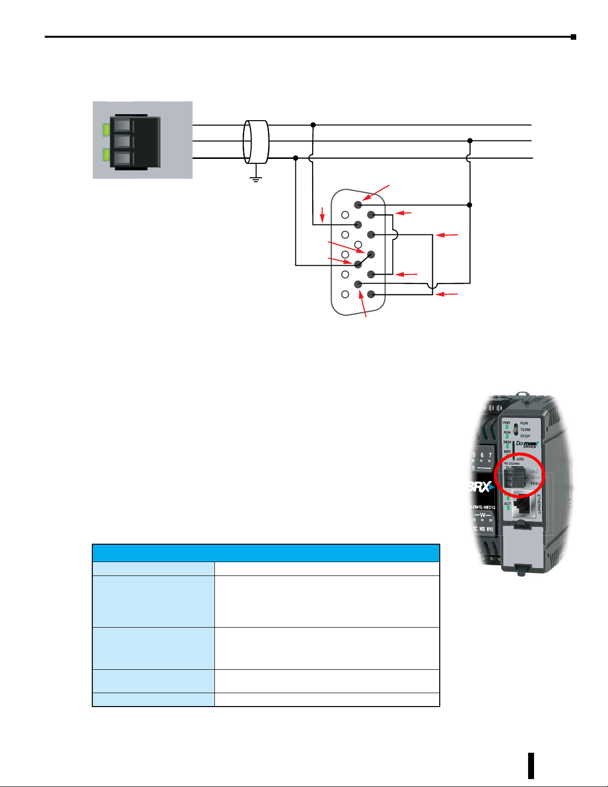
The wiring for RS-485 is shown below.
Chapter 12: BRX Do-more! Serial Communications
RS-232/485
TX
RX
GND
RX/D-
TX/D+
Signal GND
D –
D+
Belden 9841, or
equivalent, is
recommended for
RS-485 networks.
MPU Built-in Serial Port Specifications
0V
RXD+
TXD+
Signal GND
D –
D+
RXD –
6
1
7
11
10
5
15
TXD –
RTS +
CTS +
RTS –
CTS –
Jump RTS + and CTS +
Jump RTS – and CTS –
The RS-232/485 port is a removable three-pin screw terminal block located on
the front of the MPU. The port is software selectable to communicate as RS-232
or as RS-485. In the RS-485 mode you can also enable a 120 Ohm termination
resistor if needed.
The RS-232/485 port can be connected to the Do-more! Designer programming
software, Modbus RTU master or slave devices, C-more HMIs via K-Sequence
protocol, as well as devices that send or receive non-sequenced ASCII strings or
characters.
Built-in Serial Port Specifications
Port Name RS-232/RS-485 Serial Port
Non-isolated serial port that can communicate via RS-232
Description
Supported Protocols
Cable Requirements
Replacement Connector ADC Part # BX-RTB03S
or RS-485 (software selectable).
Includes ESD protection and built-in surge protection.
Includes internal biasing to be a true failsafe receiver while
maintaining EIA/TIA-485 compatibility.
Do-more! Protocol (Default)
Modbus RTU (Master & Slave)
K-Sequence (Slave)
ASCII ( In & Out)
RS-232 use L19772-XXX from AutomationDirect.com
RS-485 use L19827-XXX from AutomationDirect.com
BRX User Manual, 4th Edition, Rev. F
12-13
Page 14
Chapter 12: BRX Do-more! Serial Communications
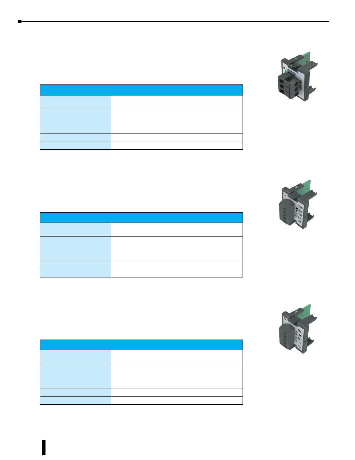
POM Specifications
BX-P-SER2-TERM
This RS-232 POM can be connected to the Do-more! Designer programming
software, Modbus RTU master devices, C-more HMIs via K-Sequence protocol, as
well as devices that send or receive non-sequenced ASCII strings or characters.
BX-P-SER2-TERM Specifications
Description
Supported Protocols
Cable Requirements RS-232 use L19772-XXX from AutomationDirect.com
Replacement Connector ADC Part # BX-RTB03S
BX-P-SER2-TERMFC
Non-isolated Serial port that can communicate via RS-232.
Includes ESD protection and built-in surge protection.
Do-more! Protocol (Default)
Modbus RTU (Master & Slave)
K-Sequence (Slave)
ASCII ( In & Out)
Removable Connector
Included
This RS-232 POM can be connected to the Do-more! Designer programming
software, Modbus RTU master devices, C-more HMIs via K-Sequence protocol, as
well as devices that send or receive non-sequenced ASCII strings or characters.
BX-P-SER2-TERMFC Specifications
Description
Supported Protocols
Cable Requirements RS-232 use L19853-XXX from AutomationDirect.com
Replacement Connector ADC Part # BX-RTB05S
BX-P-SER422-TERM
The RS-422 POM can be connected to the Do-more! Designer programming software,
Modbus RTU master devices, DirectLogic PLCs via K-Sequence protocol, as well as
devices that send or receive non-sequenced ASCII strings or characters.
Non-isolated Serial port that can communicate via RS-232.
Includes ESD protection and built-in surge protection.
Do-more! Protocol (Default)
Modbus RTU (Master & Slave)
K-Sequence (Slave)
ASCII ( In & Out)
BX-P-SER422-TERM Specifications
Description
Supported Protocols
Cable Requirements RS-422 use L19853-XXX from AutomationDirect.com
Replacement Connector ADC Part # BX-RTB05S
Non-isolated Serial port that can communicate via RS-422.
Includes ESD protection and built-in surge protection.
Do-more! Protocol (Default)
Modbus RTU (Master & Slave)
K-Sequence (Slave)
ASCII ( In & Out)
Removable Connector
Included
Removable Connector
Included
12-14
BRX User Manual, 4th Edition, Rev. F
Page 15
Chapter 12: BRX Do-more! Serial Communications
POM Specifications, continued
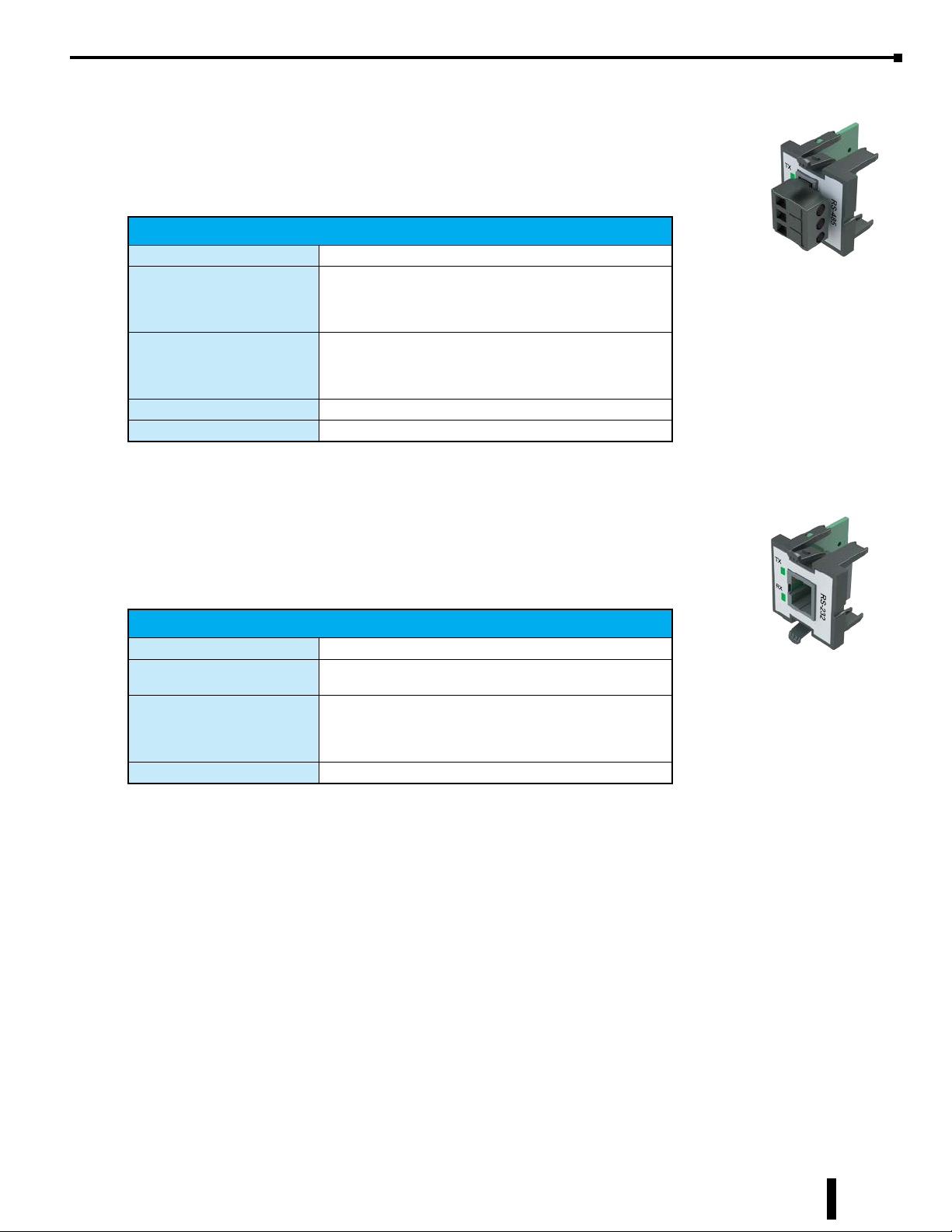
BX-P-SER4-TERM
The RS-485 POM can be connected to the Do-more! Designer programming software,
Modbus RTU master devices, C-more HMIs via K-Sequence protocol, as well as devices
that send or receive non-sequenced ASCII strings or characters.
BX-P-SER4-TERM Specifications
Port Name RS-232/RS-485 Serial Port
Non-isolated Serial port that can communicate via RS-485.
Description
Supported Protocols
Cable Requirements RS-485 use L19827-XXX from AutomationDirect.com
Replacement Connector ADC Part # BX-RTB03S
Includes ESD protection and built-in surge protection.
Includes internal biasing to be a true failsafe receiver while
maintaining EIA/TIA-485 compatibility.
Do-more! Protocol (Default)
Modbus RTU (Slave)
K-Sequence (Slave)
ASCII ( In & Out)
Removable Connector
Included
BX-P-SER2-RJ12
The RS-232 RJ12 POM can be connected to the Do-more! Designer programming
software, Modbus RTU master devices, C-more HMIs via K-Sequence protocol, as
well as devices that send or receive non-sequenced ASCII strings or characters.
BX-P-SER2-RJ12 Specifications
Port Name RS-232 Serial Port
Description
Supported Protocols
Cable Requirements RS-232 use L19772-XXX from AutomationDirect.com
Non-isolated Serial port that can communicate via RS-232.
Includes ESD protection and built-in surge protection.
Do-more! Protocol (Default)
Modbus RTU (Slave)
K-Sequence (Slave)
ASCII ( In & Out)
BRX User Manual, 4th Edition, Rev. F
12-15
Page 16
Chapter 12: BRX Do-more! Serial Communications
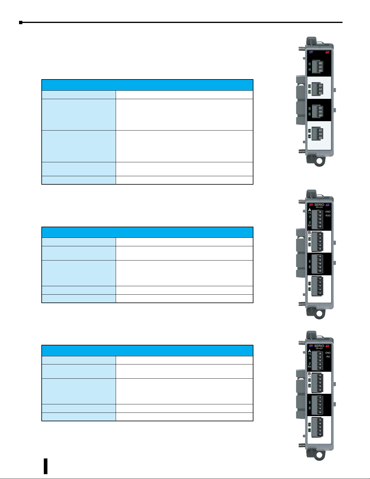
Serial Expansion Modules Specifications
BX-SERIO Expansion Module Specifications
The BX-SERIO expansion module adds four additional serial ports to any BRX system.
Up to 8 modules can be added to an MPU depending on the MPU model.
BX-SERIO Expansion Module Port Specifications
Port Name RS-232/RS-485 Serial Port
Isolated serial port that can communicate via RS-232 or
RS-485 (software selectable).
Description
Includes ESD protection and built-in surge protection.
Includes internal biasing to be a true failsafe receiver while
maintaining EIA/TIA-485 compatibility.
Do-more! Protocol (Default)
Modbus RTU (Master & Slave)
Supported Protocols
K-Sequence (Slave)
ASCII ( In & Out)
DMX512 (Master & Slave)
Cable Requirements
RS-232 use L19772-XXX from AutomationDirect.com
RS-485 use L19827-XXX from AutomationDirect.com
Replacement Connector ADC Part # BX-RTB03S (4 required)
BX-SERIO-2 Expansion Module Specifications
The BX-SERIO-2 expansion module adds four additional serial ports to any BRX
system. Up to 8 modules can be added to an MPU depending on the MPU model.
BX-SERIO-2 Expansion Module Port Specifications
Port Name RS-232 Serial Port
Description
Supported Protocols
Cable Requirements Use L19853-XXX from AutomationDirect.com
Replacement Connector ADC Part # BX-RTB05S (4 required)
Isolated serial port that can communicate via RS-232
Includes ESD protection and built-in surge protection.
Do-more! Protocol (Default)
Modbus RTU (Master & Slave)
K-Sequence (Slave)
ASCII ( In & Out)
SERIO
RS-232/485
A
TX
GND
RX/D-
TX/D+
RX
RS-232/485
B
TX
GND
RX/D-
TX/D+
RX
C
RS-232/485
TX
GND
RX/D-
TX/D+
RX
RS-232/485
D
TX
GND
RX/D-
TX/D+
RX
BX-SERIO
4 Removable Connectors Included
SERIO
RS-232
A
GND
TX
RXD
TXD
RTS
RX
CTS
B
GND
TX
RXD
TXD
RTS
RX
CTS
C
GND
TX
RXD
TXD
RTS
RX
CTS
D
GND
TX
RXD
TXD
RTS
RX
CTS
BX-SERIO-2
12-16
BX-SERIO-4 Expansion Module Specifications
The BX-SERIO-4 expansion module adds four additional serial ports to any BRX
system. Up to 8 modules can be added to an MPU depending on the MPU model.
BX-SERIO-4 Expansion Module Port Specifications
Port Name RS-422 Serial Port
Description
Supported Protocols
Cable Requirements Use L19853-XXX from AutomationDirect.com
Replacement Connector ADC Part # BX-RTB05S (4 required)
BRX User Manual, 4th Edition, Rev. F
Isolated serial port that can communicate via RS-422
Includes ESD protection and built-in surge protection.
Do-more! Protocol (Default)
Modbus RTU (Master & Slave)
K-Sequence (Slave)
ASCII ( In & Out)
4 Removable Connectors Included
SERIO
RS-422
A
GND
TX
RX
B
TX
RX
C
TX
RX
D
TX
RX
BX-SERIO-4
GND
GND
GND
RX-
RX+
TX-
TX+
RX-
RX+
TX-
TX+
RX-
RX+
TX-
TX+
RX-
RX+
TX-
TX+
4 Removable Connectors Included
Page 17
Serial Port Setup and Programming
Serial Port Settings
Setting up your serial port is straightforward. Follow the simple steps below.
1. You must know what physical medium your connecting device uses.
2. Establish which protocol your device supports.
3. Wire the physical medium using the wiring diagrams for either RS-232 or RS-485 on the previous
pages.
4. Select supported protocol from the configuration list in the Do-more! Designer software.
5. Select baud rate, data bits, stop bits and parity for your device.
6. Set the baud, data bits, stop bits and parity to match your device and Do-more! Designer software.
7. If your device is a Client (Master) device such as an HMI, then your setup is completed.
8. If your device is a Server (Slave) device and the BRX Do-more! MPU will be requesting data from it,
then some ladder logic must be written. Please refer to the specific section for your chosen protocol.
The Do-more! Designer software help file is also a good resource for setting up communications.
Chapter 12: BRX Do-more! Serial Communications
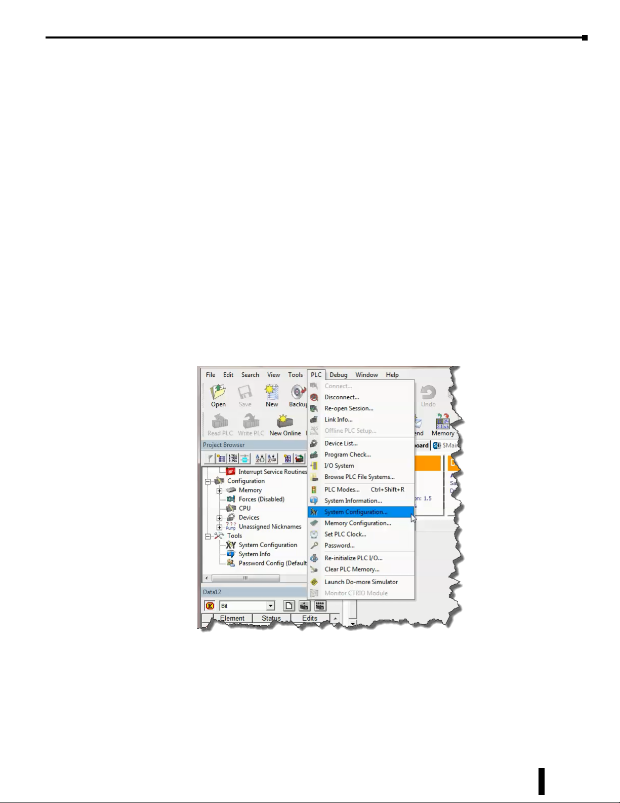
To set up your serial communications port in Do-more! Designer, from the PLC drop-down menu at the top
of the screen, select System Configuration.
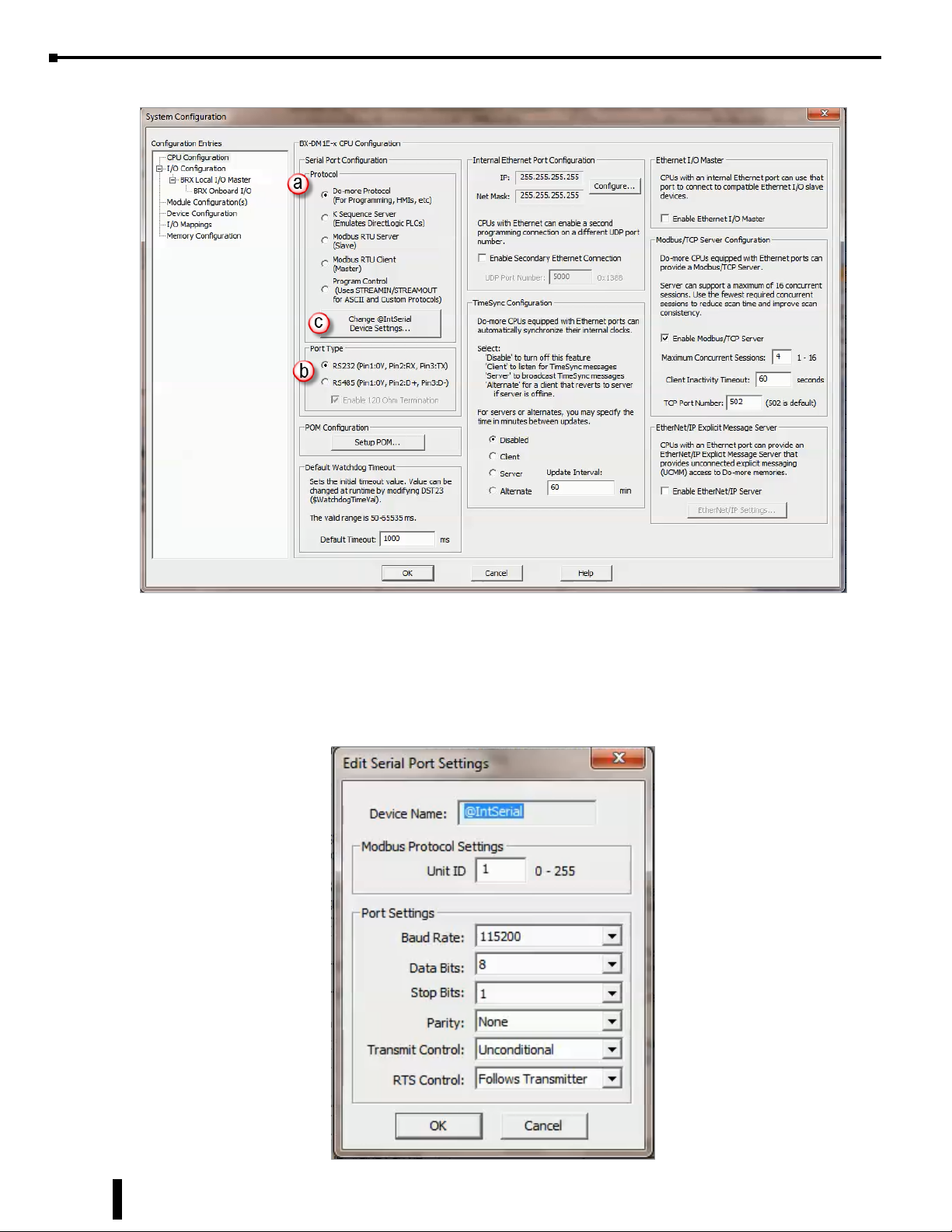
The System Configuration dialog will appear. Within this dialog box you can (a) pick the Protocol and (b)
Port Type, whether the port should be used for RS-232 or RS-485.
BRX User Manual, 4th Edition, Rev. F
12-17
Page 18
Chapter 12: BRX Do-more! Serial Communications
Serial Port Settings, continued
Once you have selected the desired Protocol and Port Type, click (c) the button labeled Change @IntSerial
Device Settings.
The Edit Serial Port Settings dialog (below) will appear. Here you will configure the serial port settings
to match any additional device(s) settings. These settings must match exactly in order for the devices to
communicate properly.
12-18
BRX User Manual, 4th Edition, Rev. F
Page 19

Serial Port Settings, continued
Unit ID – This is the Modbus protocol identification number when the BRX Do-more! MPU functions
as a server (slave) device. For RS-232 this value should always be set to 1. For RS-485, this value will
depend on how many other devices are present on the network and how they are to be numbered.
Baud Rate – The rate at which the data is transmitted. The higher the number the faster the data will be
transmitted. Choosing a lower value can help with issues when the data is not being received reliably.
Available Baud Rate choices: 115200, 57600, 38400, 19200, 9600, 4800, 2400, 1200
Data Bits – The number of bits in each character.
Available choices: 7 or 8.
Stop Bits – The number of bits sent to denote the end of each character.
Available choices: 1 or 2.
Parity – The method of error detection used during transmission.
Available choices: None, Odd, Even
Transmit Control – Designates when data will be transmitted.
Delayed 5ms, delayed 50ms, delayed 250ms, delayed 500ms – After data reaches the output buffer,
the RTS line (internal) will be asserted, and the transmitting of the data will be delayed by the
selected number of milliseconds.
Chapter 12: BRX Do-more! Serial Communications
RTS Control – There are four settings for RTS Control. Follow Transmitter is the recommended option.
Follows Transmitter puts the RTS line under the control of the transmitter.
Manual allows programmatic control of the RTS line through the structure member IntSerial.RTS.
Off forces the RTS line to always be OFF.
On forces the RTS line to always be ON.
The following options are available when Modbus RTU Client (Master) is selected:
Timeout – how many milliseconds should the instruction wait for the remote Modbus RTU Server
(Slave) to respond; this can be any constant from 0 to 32767.
Retries – how many times should the instruction retry the communication with the remote Modbus
RTU Server (Slave); this can be any constant from 0 to 255.
Inter-packet Delay – the amount of time (in microseconds) the Modbus/RTU Client (Master) will place
between packets as they are sent; this can be any be any constant value between 0 and 65535.
BRX User Manual, 4th Edition, Rev. F
12-19
Page 20
Chapter 12: BRX Do-more! Serial Communications
Serial Protocols
The BRX Do-more! MPU supports several Protocol choices for communicating to external devices. In this
section we will go over the choices and describe each choice.
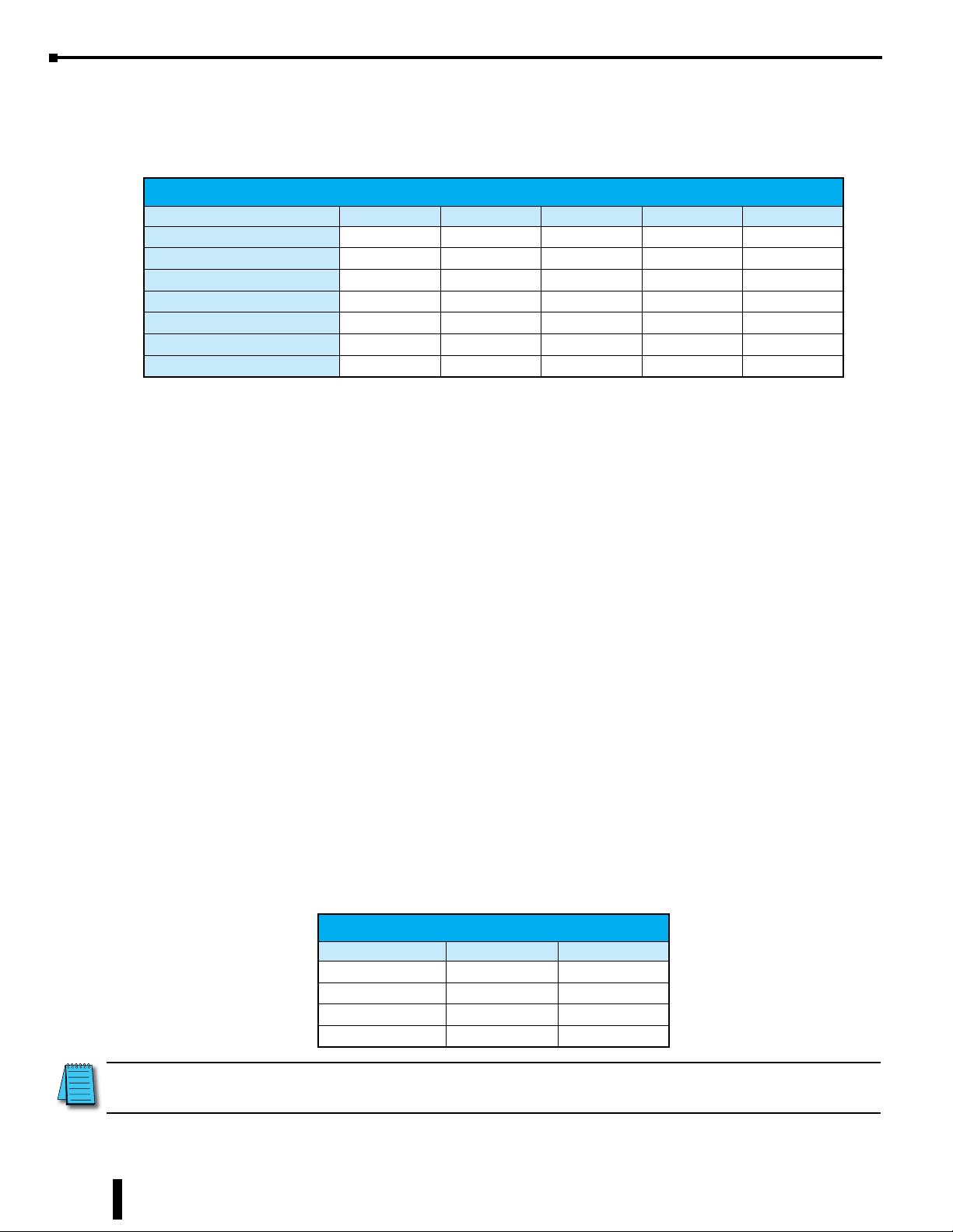
Supported Communications Protocols
Protocol Onboard Serial POMs BX-SERIO BX-SERIO-2 BX-SERIO-4
Do-more Protocol (Slave) X X X X X
Modbus RTU (Slave) X X X X X
Modbus RTU (Master) X X X X
K-Sequence (Slave) X X X X X
ASCII X X X X X
DMX512 (Controller) X
DMX512 (Slave) X
Do-more! Protocol
The Do-more! protocol is a proprietary protocol that is used exclusively by the Do-more! family of controllers.
This is a very feature rich and secure protocol that is used to communicate between the Do-more! Designer
software and Do-more! controllers. It can also be used to communicate between multiple Do-more! controllers
or to other devices such as the C-more HMI and some SCADA systems that support the Do-more! Protocol.
Modbus RTU
Modbus RTU is a protocol overseen by Modbus.org. This is an open standard, meaning that anyone can
utilize it freely.
Modbus RTU can be utilized as either a client or server configuration. When using RS-485, Modbus RTU
supports a single Client (Master) device communicating to multiple Server (Slave) devices. When using
RS-232, Modbus RTU supports a single Client (Master) device communicating to a single Server (Slave)
device.
Modbus RTU Server (Slave)
As a Modbus RTU Server, the BRX MPU is functioning as a listening/replying device. When an external
Client device requests data from the BRX MPU, the MPU will reply with the appropriate data.
All Modbus data is stored in four sets of registers in the BRX MPU. This memory area is blocked off
specifically for Modbus communications. You must place data in these registers in order for a Modbus device
to be able to access it.
Modbus
Register Type Register Name Range
Holding Coil MC 00000–01023
Input Coil MI 10000–11023
Holding Register MHR 40000–42047
Input Register MIR 30000–31047
12-20
NOTE: Ranges can be expanded in the Memory Configuration section of the Do-more! Designer software as needed.
BRX User Manual, 4th Edition, Rev. F
Page 21
Chapter 12: BRX Do-more! Serial Communications
Modbus RTU Server (Slave), continued
The Modbus data area is loosely data typed and casting or other instructions such as PUBLISH and
SUBSCRIBE can be utilized to convert data in this area to the correct data type required. Please reference
the Help file on casting, PUBLISH and SUBSCRIBE.
The Modbus RTU Server (Slave) supports the following function codes:
Modbus
Function Code Description
1 Read coil
2 Read discrete inputs
3 Read holding registers
4 Read input registers
5 Write single coil
6 Write single registers
7 Read exception status
15 Write multiple coils
16 Write multiple registers
22 Mask write registers
Modbus RTU Client (Master)
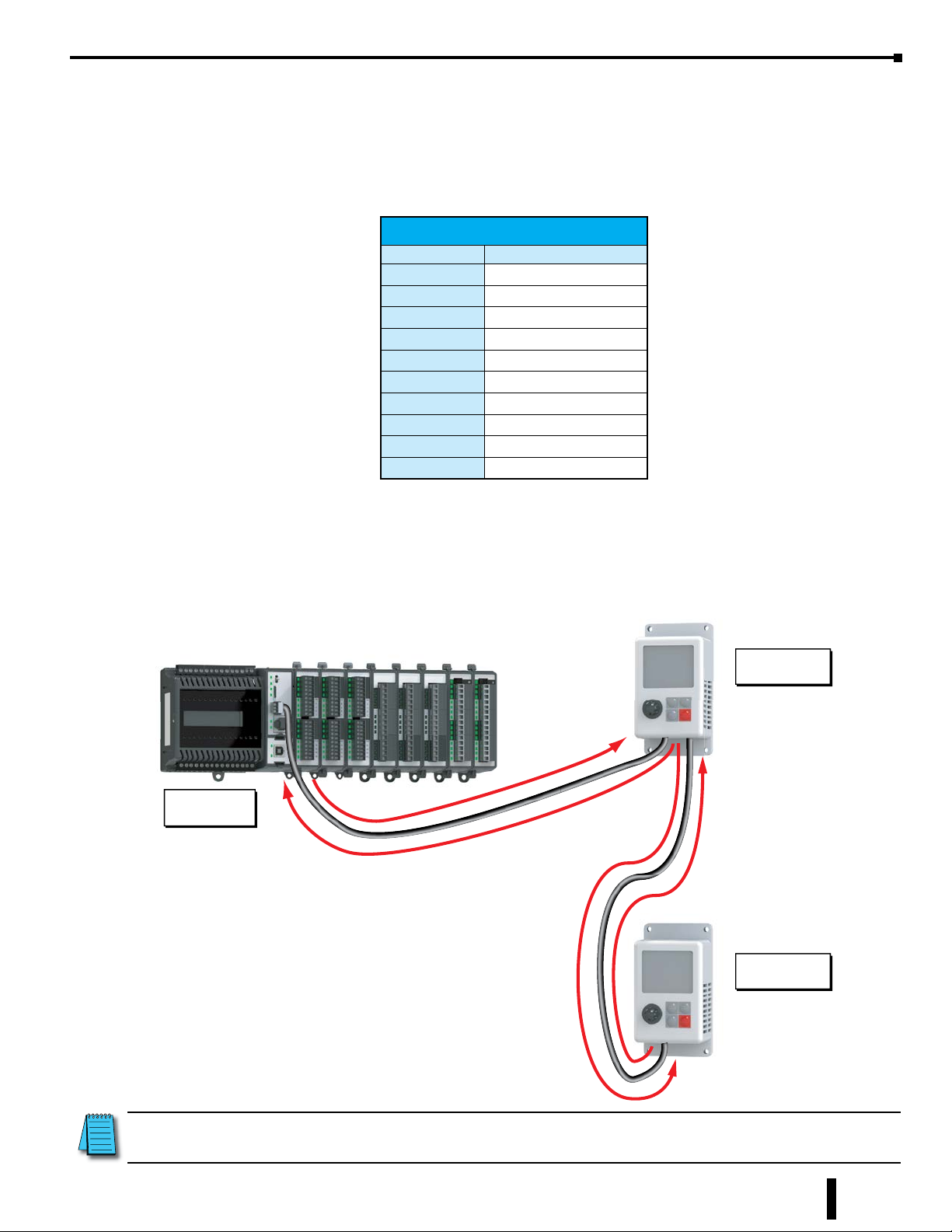
As a Modbus RTU Client, the BRX MPU is requesting data from a Modbus RTU Server device. In order for
this to work, you need to know quite a few things about your Server device such as the function codes that it
supports, the data registers that are accessible and possibly the Unit ID or Slave Address.
Server Device
Unit ID 1
BRX MPU
Client Device
Server Device
Unit ID 2
BRX MPU used as a Modbus RTU Client (Master) Example
NOTE: Only one Modbus RTU Client (Master) can be on a network.
BRX User Manual, 4th Edition, Rev. F
12-21
Page 22
Chapter 12: BRX Do-more! Serial Communications
Modbus RTU Client (Master), continued
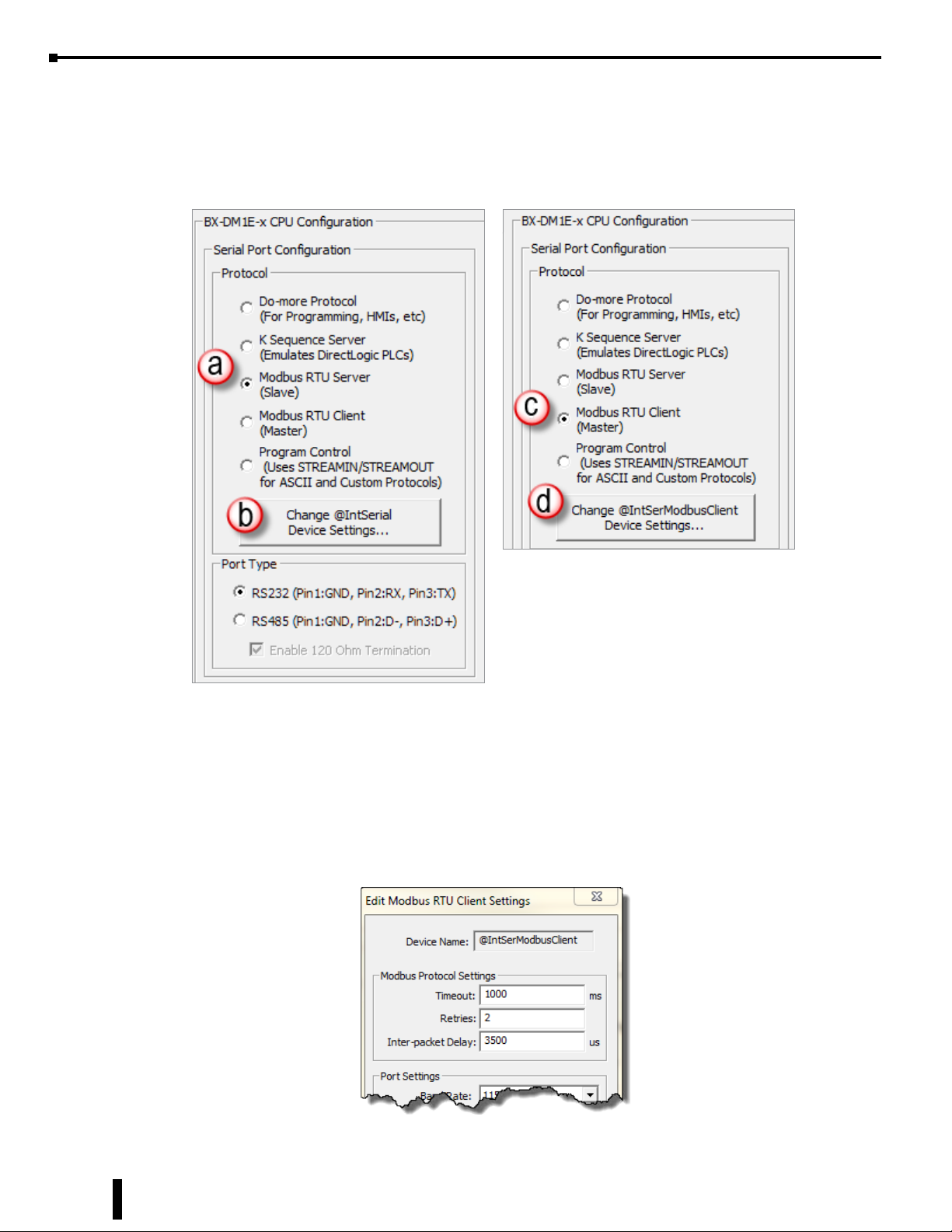
Opening the System Configuration dialog box you will find the Serial Port Configuration section where
you can select the required protocol. Setting the serial port as (a) Modbus RTU Server, select (b) to create a
the device @IntSerialDevice. This device will handle all of the communications with the external Modbus
Servers through a BRX serial port.
As a Modbus RTU Client, you do not have to sequence the MRX read and MWX write instructions. You
can just drop them into your program and they will work in a round robin manner. However, sequencing
the instructions will give you better control and allow you to build complex communication patterns to
optimally communicate with your devices.
Selecting (c) Modbus RTU Client (Master) creates the device @IntSerModbusClient. Clicking on (d) brings
up the Edit Modbus RTU Client Settings dialog box (below). Here you can configure Modbus Protocol
Settings.
12-22
BRX User Manual, 4th Edition, Rev. F
Page 23
Chapter 12: BRX Do-more! Serial Communications
Modbus RTU Client (Master), continued
Timeout – Time in milliseconds that the instruction waits for the remote Modbus RTU Server to
respond, this can be any constant from 0 to 32767.
Retries – The number of retries of the instruction to communicate with the remote Modbus RTU Server,
this can be any constant from 0 to 255.
Inter-packet Delay – Time, in microseconds, that the Modbus RTU Client will place between packets
as they are sent, this can be any be any constant value between 0 and 65535.
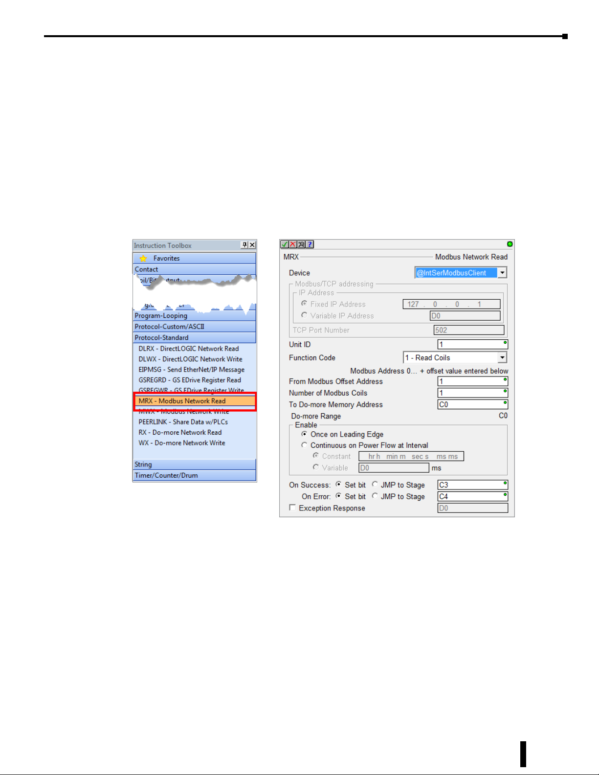
MRX Instruction
The MRX instruction, found in the Instruction Tool Box under the Protocol-Standard tab (below), is used
to read from a Modbus RTU Server. (For more detailed information please refer to the Do-more! Designer
Help files.)
Device – The device associated with the physical port that you want to communicate from.
@IntSerModbusClient is the name of the device associated with the built in serial port when set as a
Modbus Client (Master).
Unit ID – The ID number of the Server device that the BRX MPU will talk to. Typically this is 1 for
RS-232. For RS-485, this number could change depending on which device number you are talking
to on the network.
Function Code – Select from the drop-down list one of the following Modbus function codes to use:
1 - Read Coils
2 - Read Discrete Inputs
3 - Read Holding Registers
4 - Read Input Registers
7 - Read Exception Status
BRX User Manual, 4th Edition, Rev. F
12-23
Page 24

Chapter 12: BRX Do-more! Serial Communications
MRX Instruction, continued
Modbus Address 0... + offset value entered below:
From Modbus Offset Address – The address in the Modbus Server that you will be reading from.
This address may be offset by a value of +1 depending on how the manufacturer followed the Modbus
standard..
Number of Modbus Coils/ Registers – Based on the Function Code selected, this selection specifies
how many consecutive elements to read. For example, if using function code 3, read holding registers,
with an offset of 1, and you request 2 consecutive registers, you will read the value in Modbus
addresses 400001 and 400002.
To Do-more! Memory Address – Specifies the beginning address of a range of bits or numeric
locations in the MPU where the data that is read will be stored. This data type (bit or register) must
match the type expected by the Function Code.
Do-more Range – This is the ending register where the data will be stored at, calculated by taking the To
Do-more Memory address and adding the Number of Modbus Coils/Registers value to it.
Enable – Designates how this instruction will operate. Select from one of the following:
Once on Leading Edge – Select this option to have this instruction run to completion exactly one
time. Typically, this instruction will take more than one controller scan to complete. Configured this
way the instruction is Edge Triggered.
Continuous on Power Flow at Interval – Select this option to have this instruction run as long as
the instruction has power flow. After the instruction has initially run, if the instruction still has power
flow, the instruction will remain enabled and will wait the specified amount of time before running
again. The following options select how much time (in milliseconds) to wait between successive runs.
A value of zero milliseconds (0ms) means the instruction will re-run immediately.
On Success – When the instruction completes successfully this action will be performed.
Set Bit – Enable this selection then specify any writable bit location.
JMP to Stage – Enable this selection then specify any Stage number from S0 to S127 in the current
Program code-block.
On Error – When the instruction does not complete successfully this action will be performed.
Set Bit – Enable this selection then specify any writable bit location.
JMP to Stage – Enable this selection then specify any Stage number from S0 to S127 in the current
Program code-block.
Exception Response – For errors where the message was received properly by the Server device, this will
contain a value to indicate why the Server rejected the message. This can aid in troubleshooting the
issue.
12-24
BRX User Manual, 4th Edition, Rev. F
Page 25
Chapter 12: BRX Do-more! Serial Communications
MWX Instruction
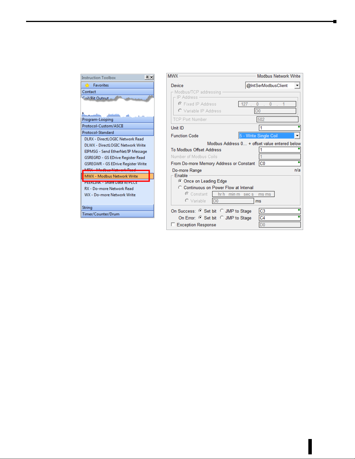
The MWX instruction, found in the Instruction Tool Box under Protocol - Standard (right and below), is
used to write to a Modbus RTU Server. (For specific information please refer to the Do-more! Designer help
files.)
Device – The device associated with the physical port that you want to communicate from.
@IntSerModbusClient is the name of the device associated with the built in serial port when set as
a Modbus Client (Master).
Unit ID – The ID number of the Server device the BRX MPU is talking to. Typically this is 1 unless
there are multiple devices on the network.
Function Code – Select from the drop-down list one of the following Modbus function codes to use:
5 - Write Single Coil
6 - Write Single Register
15 - Write Multiple Coils
16 - Write Multiple Registers
Modbus Address 0... + offset value entered below:
To Modbus Offset Address – The starting register to which you will be writing data. This address
may be offset by a value of +1 depending on how the manufacturer followed the Modbus standard.
Number of Modbus Coils/ Registers – This selection specifies how many consecutive elements to
write from the Modbus Offset Address. For example, if using function code 6,write a single register,
with an offset of 1, it would write a value to Modbus address 400001.
From Do-more Memory Address – specifies the beginning address of a range of bits or numeric
locations in the MPU to where the data will be written. This data type (bit or register) must match
the type expected by the Function Code.
BRX User Manual, 4th Edition, Rev. F
12-25
Page 26
Chapter 12: BRX Do-more! Serial Communications
MWX Instruction, continued
Do-more Range – This is the ending register from where the data will be written, calculated by taking
the From Do-more! Memory address and adding the Number of Modbus Coils/Registers value to it.
Enable – Designates how this instruction will operate. Select from one of the following:
Once on Leading Edge - Select this option to have this instruction run to completion exactly one
time. Typically, this instruction will take more than one controller scan to complete. Configured this
way the instruction is Edge Triggered.
Continuous on Power Flow at Interval - Select this option to have this instruction run as long as
the instruction has power flow. After the instruction has initially run, if the instruction still has power
flow, the instruction will remain enabled and will wait the specified amount of time before running
again. The following options select how much time (in milliseconds) to wait between successive runs.
A value of 0ms means the instruction will re-run immediately.
On Success – When the instruction completes successfully this action will be performed.
Set Bit – Enable this selection then specify any writable bit location.
JMP to Stage – Enable this selection then specify any Stage number from S0 to S127 in the current
Program code-block.
On Error – When the instruction does not complete successfully this action will be performed.
Set Bit – Enable this selection then specify any writable bit location.
JMP to Stage – Enable this selection then specify any Stage number from S0 to S127 in the current
Program code-block.
Exception Response – For errors where the message was received properly by the Server device, this will
contain a value to indicate why the Server rejected the message. This can aid in troubleshooting the
error issue.
K-Sequence Server (Slave)
The BRX Do-more! MPU can serve as a K-Sequence server to communicate to legacy devices that utilize the
K-Sequence protocol such as C-more HMI, SCADA systems, etc.
All K-Sequence data is stored in four sets of registers in the BRX Do-more! MPU. The memory area is
blocked off specifically for K-Sequence communications. You must place data in these registers in order for a
K-Sequence Client device to be able to access it.
The K-Sequence data area is loosely data typed. Instructions such as Publish and Subscribe can be utilized to
convert data in this area to the proper data type needed as well. Please see the Help file for more information
on Casting, PUBLISH and SUBSCRIB (Help topics DMD0309, DMD0073 and DMD0074, respectively).
K-Sequence
Register Type Register Name Range
Input Register DLX 0–777
Output Register DLY 0–777
Internal Coil Register DLC 0–777
Internal Word Register DLV 0–3777
12-26
NOTE: Ranges can be expanded in the Memory Configuration section of the Do-more! Designer software as needed.
BRX User Manual, 4th Edition, Rev. F
Page 27
Chapter 12: BRX Do-more! Serial Communications
ASCII
The BRX Do-more! MPU can communicate with devices that utilize a non-sequenced or a custom protocol.
When using ASCII messaging it is important to know how the external device communicates. This will
require knowledge of how the external device expects to send and receive the data. Most ASCII devices have
specification guidelines in the user manual that explain the methods needed to facilitate communications.
Having this reference handy can be invaluable, saving time while programming instead of struggling with
getting the communications working.
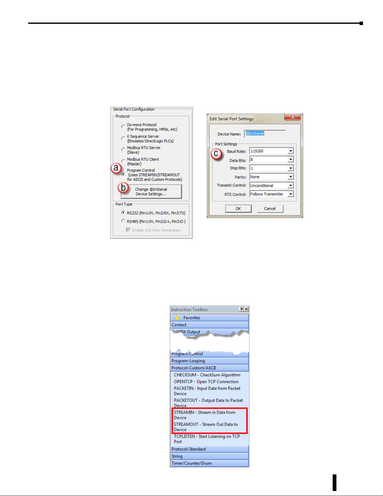
Utilizing ASCII as a messaging medium requires that the serial port (a) be set to Program Control. To
configure the port settings select (b) the Change @IntSerial Device Settings button. This will bring up the
(c) Edit Serial Port Settings dialog. The communications settings here need to match those of the device you
are communicating with.
Once set, the STREAMIN and STREAMOUT instructions can be utilized.
BRX User Manual, 4th Edition, Rev. F
12-27
Page 28

Chapter 12: BRX Do-more! Serial Communications
ASCII, continued
One beneficial feature of the BRX Do-more! MPU is that the serial ports are buffered so that bi-directional
data transfer is possible without needing the external device to pause between sending and receiving.
ASCII: STREAMIN Instruction
The STREAMIN instruction is found in the Instruction Tool Box under the Protocol-Custom/ASCII tab.
Device – The device name associated with the physical port to which you want to communicate.
@IntSerial is the name of the device associated with the built in serial port for ASCII control.
Complete when...
Length is...bytes OR – Specifies the number of characters received that will signal the completion of
the instruction. The OR is used if Delimiter(s) received OR is selected.
Delimiter(s) received OR – Message characters that once received will signal the completion of the
instruction. The OR implements:
Exact sequence – The specified characters must be received in the order specified
Any one delimiter(s) – Receipt of any of the specified characters will signal completion.
Trim Delimiter(s) from Output String – Removes the delimiter characters from the Data
Destination.
Network Timeout – The maximum amount of time that the instruction waits for completion.
Advanced – When selected a text box opens on the right. Allows the backspace character to remove
characters from the received string before being placed into the Data Destination.
Data Destination
String Structure – The String memory location for the incoming data to be stored.
12-28
Numeric Data Block
Start Address – The offset into the Byte Buffer Data Block to store the incoming data.
BRX User Manual, 4th Edition, Rev. F
Page 29
Chapter 12: BRX Do-more! Serial Communications
ASCII: STREAMIN Instruction, continued
Create Byte Buffer – Creates a data block of bytes to store the incoming data.
Buffer Size in Bytes – The maximum number of bytes that will be placed in the Byte Buffer
Data Block.
Number of Bytes Read – Stores the number of bytes that were read into the Byte Buffer Data Block.
Endian Settings
Swap Byte – Swaps the bytes in each word of incoming data.
Swap Word – Swaps the words in each Double Word of incoming data.
On Success – When the instruction completes successfully this action will be performed.
Set Bit – Enable this selection then specify any writable bit location.
JMP to Stage – Enable this selection then specify any Stage number from S0 to S127 in the current
Program code-block.
On Error – When the instruction does not complete successfully this action will be performed.
Set Bit – Enable this selection then specify any writable bit location.
JMP to Stage – Enable this selection then specify any Stage number from S0 to S127 in the current
Program code-block.
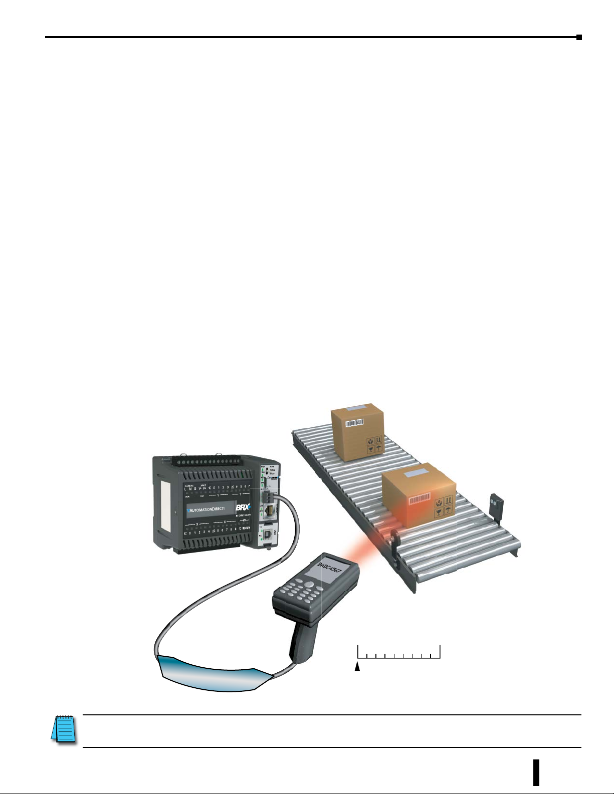
A barcode reader is an example of using STREAMIN and ASCII messaging. The string “BADC 4567”
represented by the barcode is transmitted to the MPU as ASCII text with the use of the STREAMIN instruction.
NOTE: Using @IntSerial.InQueue > 0 is the best way to trigger the STREAMIN function.
BRX User Manual, 4th Edition, Rev. F
BADC 45 6 7
123456789
Begin
String
12-29
Page 30
Chapter 12: BRX Do-more! Serial Communications
ASCII: STREAMOUT Instruction
The STREAMOUT instruction is found in the Instruction Tool Box under the Protocol-Custom/ASCII tab.
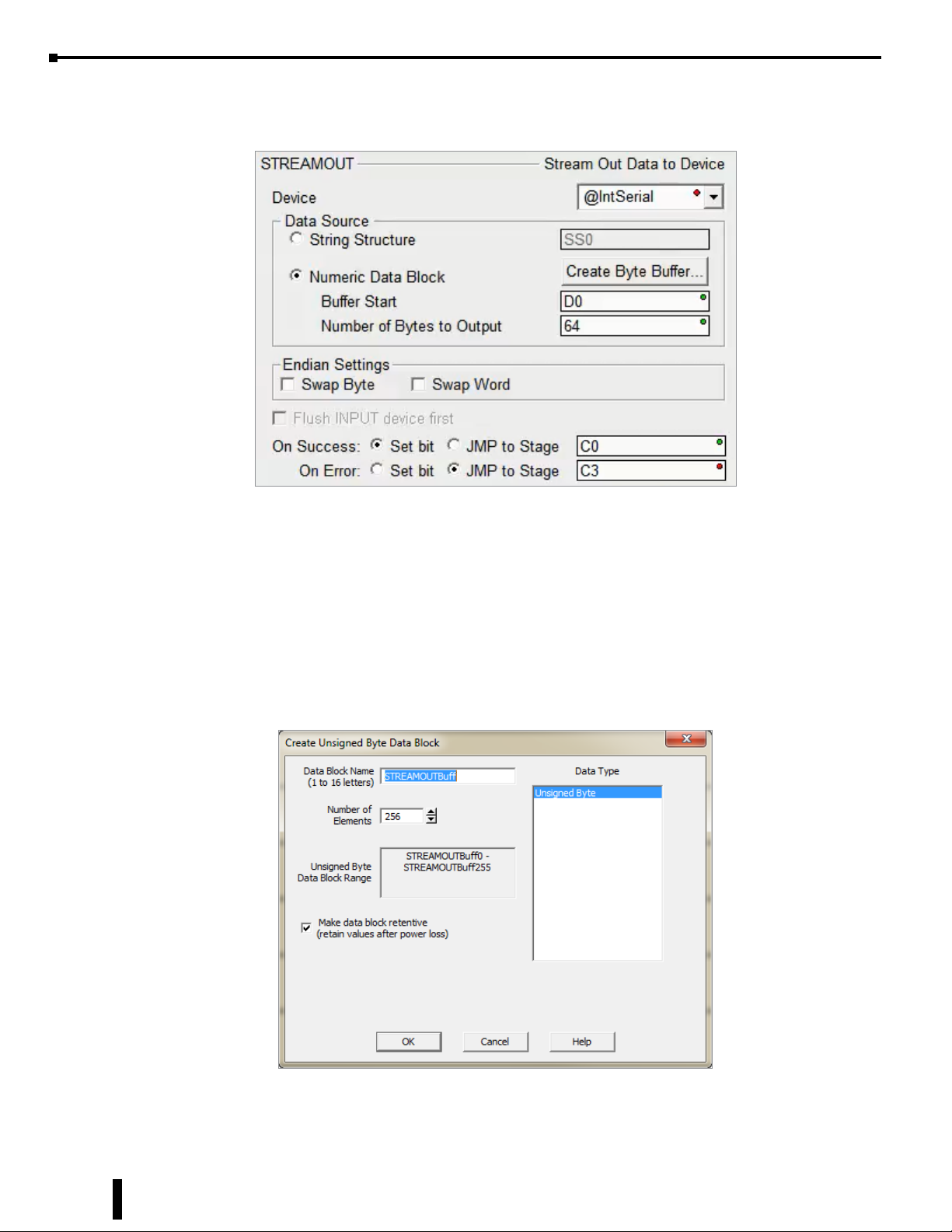
Device – The device associated with the physical port from which you want to communicate. @IntSerial
is the name of the device associated with the built in serial port for ASCII control.
Data Source
String Structure – The String memory location that contains the data to be transmitted.
Numeric Data Block
– Create Byte Buffer – Only available when Numeric Data Block is selected. Clicking this button
opens Create Unsigned Byte Data Block box (below). Here you will name and create a data block
of bytes to store the data to be transmitted.
12-30
– Buffer Start – The offset into the Byte Buffer Data Block for the data to be transmitted.
– Number of Bytes to Output – The number of bytes that will be transmitted.
BRX User Manual, 4th Edition, Rev. F
Page 31
Chapter 12: BRX Do-more! Serial Communications
ASCII: STREAMOUT Instruction, continued
Endian Settings
Swap Byte – Swaps the bytes in each word of data.
Swap Word – Swaps the words in each Double Word of data.
Flush INPUT device first – Clears the input buffer to ready it for a return response.
On Success – When the instruction completes successfully this action will be performed.
Set Bit – Enable this selection then specify any writable bit location.
JMP to Stage – Enable this selection then specify any Stage number from S0 to S127 in the current
Program code-block.
On Error – When the instruction does not complete successfully this action will be performed.
Set Bit – Enable this selection then specify any writable bit location.
JMP to Stage – Enable this selection then specify any Stage number from S0 to S127 in the current
Program code-block.
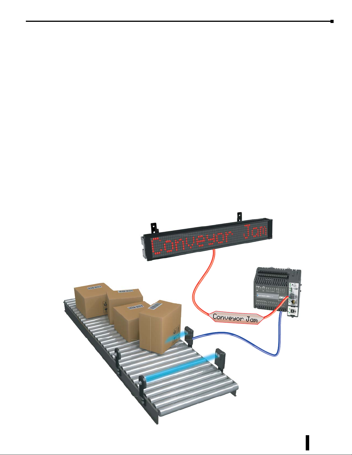
Use of the STREAMOUT instruction and ASCII messaging to display text from the BRX PLC
A sensor on the conveyor triggers a conveyor jam event in the program. The string “Conveyor Jam” is
transmitted as ASCII text with the use of the STREAMOUT instruction.
BRX User Manual, 4th Edition, Rev. F
12-31
Page 32
Chapter 12: BRX Do-more! Serial Communications
DMX512 (Master & Slave)
DMX512 is commonly used to control stage lighting, dimmers and special effects devices such as fog
machines and intelligent lights. DMX can also be used to control non-theatrical interior and architectural
lighting as well as electronic billboards.
A DMX512 network is called a “DMX universe.” Each communications port on a DMX512 controller can
control a single universe.
The physical layer of DMX12 is based on the RS-485 standard. It is unidirectional. It does not include
automatic error checking and correction, and so is not an appropriate control for hazardous applications such
as pyrotechnics or movement of theatrical rigging.
A DMX512 controller transmits data at 250 kbit/s; one start bit, eight data bits (LSB first), two stop bits
and no parity. There are up to 512 bytes of data sent with each transmission. Data transmissions occur
approximately 40 times a second. There is no reply from slave units that data was received and no checking
for data integrity.
A DMX512 network employs a multi-drop bus topology with nodes strung together in a daisy chain. Each
slave device has an IN connector and usually a THRU connector as well.
Wiring
Standard DMX512 requires twisted-pair, shielded, low-capacitance data cable designed for RS-485. The
DMX512 signal lines require a single termination resistor to be fitted at the physical end of the signal cable.
The maximum recommended length of a DMX512 run of cable is 1000 feet.
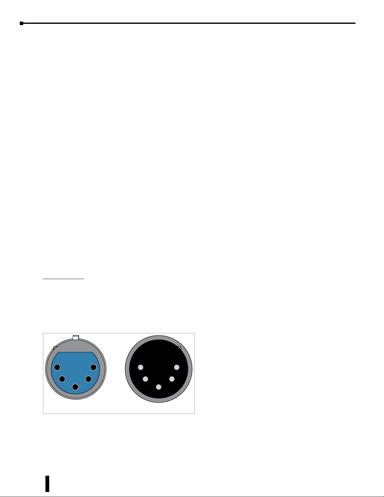
DMX512 typically uses XLR-5 or RJ-45 connectors, though non-compliant connectors such as XLR-3 are
also commonly encountered.
XLR-5 pinout
1. Signal Common
2. Data 1- (Primary Data Link)
3. Data 1+ (Primary Data Link)
4. Data 2- (Optional Secondary Data Link)
5. Data 2+ (Optional Secondary Data Link)
5 1
4 2
3
1 5
2 4
3
12-32
FEMALE MALE
XLR-5 Pinout
BRX User Manual, 4th Edition, Rev. F
Page 33
Chapter 12: BRX Do-more! Serial Communications
DMX512 (Master & Slave), continued
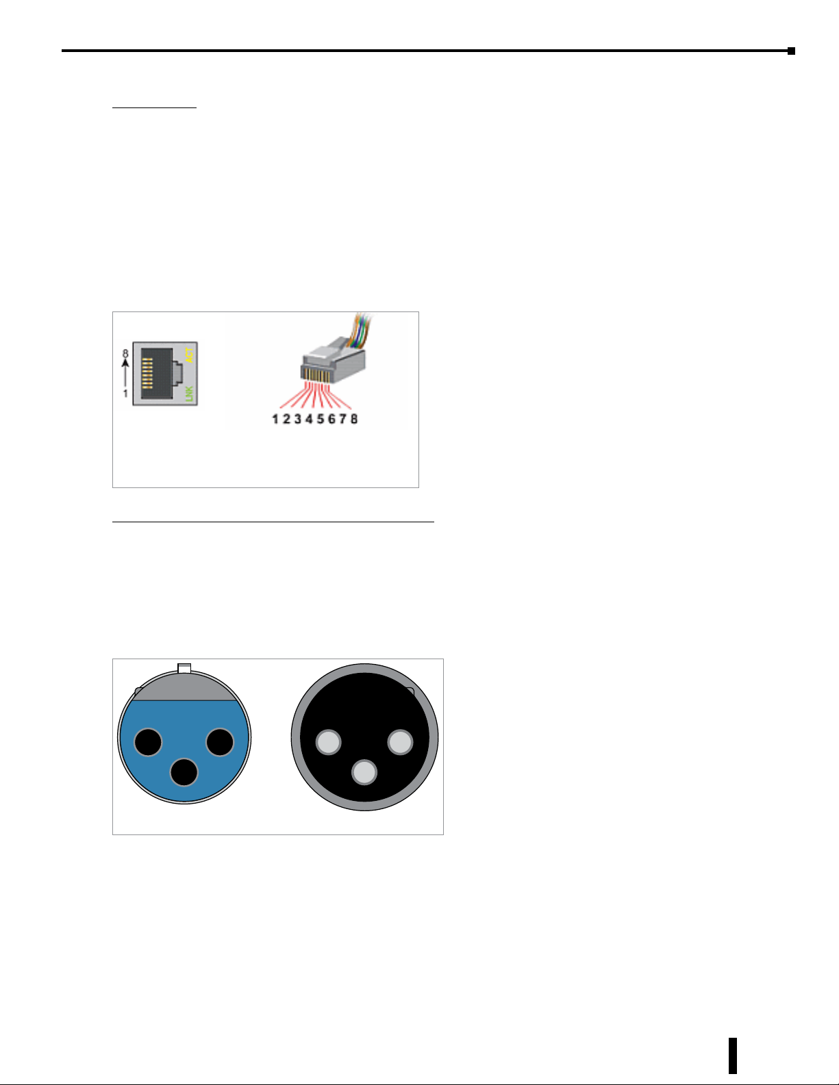
RJ-45 pinout
1. Data 1+
2. Data 1-
3. Data 2+
4. Not Assigned
5. Not Assigned
6. Data 2-
7. Signal Common (0 V) for Data 1
8. Signal Common (0 V) for Data 2
The pinout matches the wiring used by Category 5 (Cat5) twisted pair patch cables.
RJ-45 Pinout
XLR-3 pinout (common non-compliant connector)
The most commonly encountered pinout is shown.
1. Ground
2. Data 1+
3. Data 1-
Depending on manufacturer, Pin 2 and Pin 3 may be swapped. Check the device wiring diagram.
2 1
3
FEMALE MALE
1 2
3
XLR-3 Pinout
DMX data
Data for the DMX512 protocol for both master and slave is stored in a structure that is created when the
protocol is selected in the serial port setup. If you do not change the name of the serial port, it will default
to DMXA to DMXD for serial port 1 to 4 respectively. To access the data, you would use DMXx0 to
DMXx511, where x equals A, B, C or D assuming that you did not change the serial port name from default.
The values for the data range are between 0 and 255.
BRX User Manual, 4th Edition, Rev. F
12-33
Page 34

Chapter 12: BRX Do-more! Serial Communications
Notes:
12-34
BRX User Manual, 4th Edition, Rev. F
 Loading...