


1 Ref. : CH - 1249 - A - 2
1 . Standards - Regulations
2 . General
3 . Assembly and installation
4 . Installing the options
5 . Commissioning
6 . Maintenance
HIGH-EFFICIENCY, PRESSURIZED,
CAST IRON, OIL OR GAS BOILERS
70 / 290 kW
Ref. : CH - 1249 - A - 2 - EN 07/01
INSTALLATION MANUAL
NXR3

2Ref. : CH - 1249 - A - 2
1. STANDARD - REGULATIONS
BAXI does not accept any liability for damage caused by
work that does not comply with these instructions and/
or which has not been carried out by a qualified
installer.
This boiler design complies with the following European
directives:
Directive Mains voltage 73 / 23 / CEE
Directive Electromagnetic 89 / 336 / CEE
compatibility
Directive Efficiency 92 / 42 / CEE
This boiler complies with the following standards:
EN 303.1 • Boilers with forced air burner: Terminology,
general specifications, tests and marking
EN 303.2 • Boilers with forced air burner: Special
specifications for boilers with sprayed oil
burner
EN 304 • Test regulations for boilers with sprayed oil
burner
DIN 4791 • Boiler and burner connections
The boiler can be fitted with a choice of fuel oil or gas burner
in accordance with the builder’s recommendations, the burner
complying with the following standards:
EN 267 • One piece sprayed oil burner
EN 676 • Automatic blown air burner for gas fuels
EN 226 • Burner to heat generator connection sizes
The heating system installation must comply with current
regulations.
In particular:
DTU 65 • Central heating systems in buildings
DTU 65.4 • Gas and liquid hydrocarbon boilers
DTU 65.11 • Safety systems for central heating systems
in buildings
Installers’ Association agreement of 2 July 1969.
BAXI S.A. attests that all boilers referred to in this
manual comply the same requirements as corresponding
examined types, for which the right to use CE marking
has been granted according to "Gas appliance" and
"Boiler efficiency" European directives.

3 Ref. : CH - 1249 - A - 2
2. GENERAL
2 . 1 Description
Boilers of this type are composed of a cast-iron
exchanger, consisting in sections assembled by means of
nipples. Their heat transfer surfaces have been specially
designed to reach high efficiency. The exchanger is insulated
by a glass wool layer lined by lacquered steel casing panel,
itself insulated to reduce heat losses to a minimum.
These pressurized boilers must be fitted with jet-oil or blowngas burners, provided operating characteristics are compatible with the combustion chamber size and pressure conditions.
They heat premises, and, for Domestic Hot Water (D.H.W.)
production, can be coupled with a D.H.W. tank located next
to it.
2 . 2 Standard supplies
• Fire chamber cast-iron sections not assembled,
• Accessories: smoke box, optimizing baffles, flue ways
hinged door, opening chamber door with burner plate,
welding flanges for tubes Ø 76,
• Insulated casing and cleaning brush,
• Depending on the order, this boiler is fitted with a control
panel (according to version).
2 . 3 Supplied on request
• Heating body delivered assembled,
• Two extra power economizers,
• Starter sleeve with finger button for remote control sensor
and ¾” ∅ tapped opening with plug (not assembled),
• Return sleeve with finger button for remote control sensor
and ¾” ∅ drainage valve (not assembled),
• Adjustable feet for levelling body,
• Control panel options,
• OIL or GAS burner, depending on matching prescriptions,
• Domestic Hot Water calorifer (250-350-500-800)
2 . 4 Shipping, Packaging
Packaging is as follows :
Boiler
assembled
X
X
X
X
X
Boiler
not assembled
X
X
X
X
X
X
X
Package
Heating exchanger not assembled
Heating exchanger assembled
Optimizing baffles
Heating exchanger accessories
Control panel wired
Casing
Extra accessories
Tie-rods
34
7
612
5
612
35
7
730
5
730
36
7
849
5
848
37
7
963
5
950
38
7
1082
5
1068
39
7
1198
5
1184
exchanger not
assembled
Nb of parcels
Total weight kg
exchanger
assembled
Nb of parcels
Total weight kg
4Ref. : CH - 1249 - A - 2
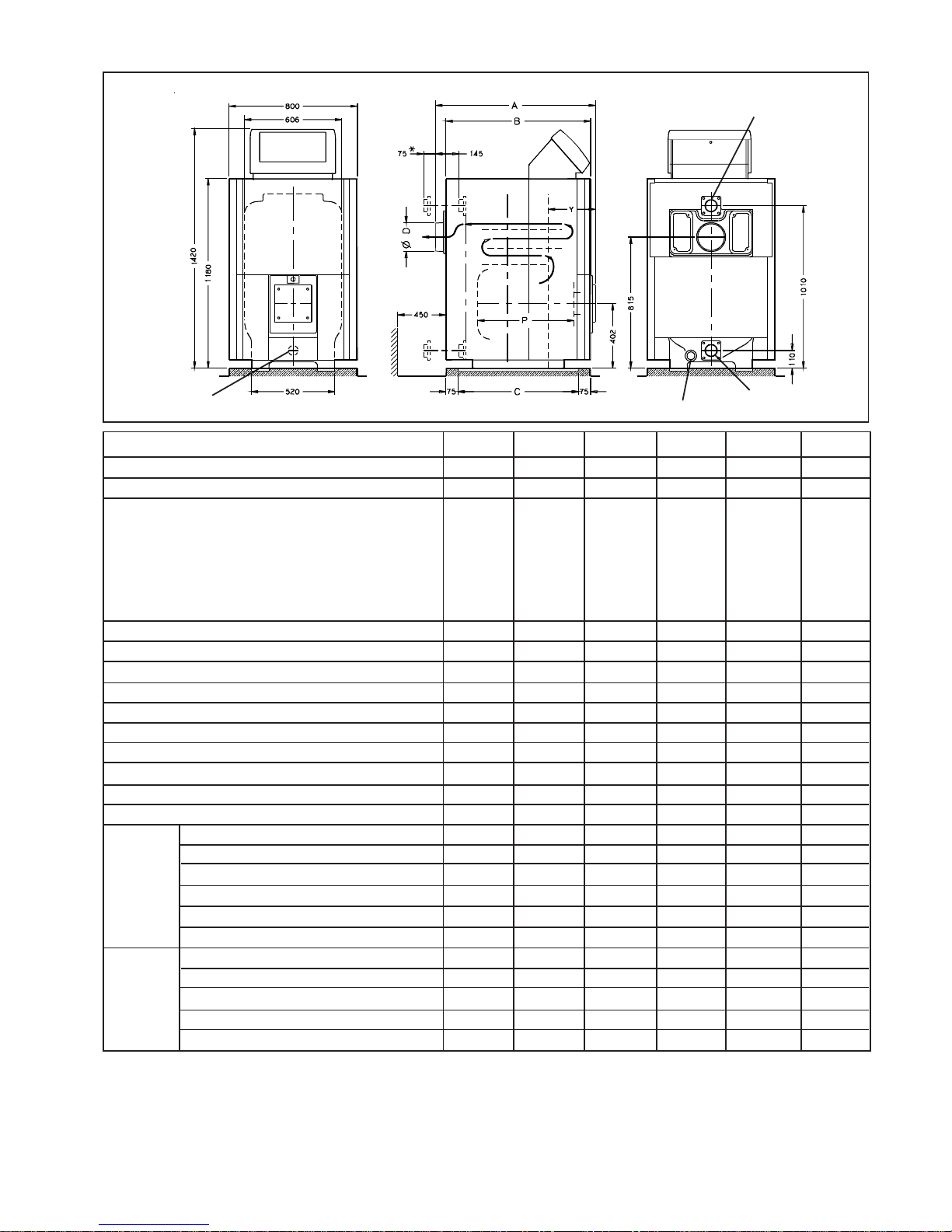
2 . 5 Technical data
Flow DN 65
Fig. 1
Return DN 65
Drain Rp 1 1/2" orifice
Rp 2" orifice for
sludge flushing
36
130-170
6
1335
1240
1090
292
935
180
170
270
160
6
15
30-90
110
0,11
0,40
140-185
0,5-0,8
201-265
232-306
161-180
92,7 - 93 6
139 - 183
0,5 - 1,0
199 - 262
229 - 303
147 - 166
93,4 - 94,2
39
250-290
9
1845
1750
1600
292
1445
200
260
390
232
6
50
30-90
110
0,07
0,25
271-317
1,5-2,3
388-454
448-524
170-188
92,4 - 93,2
270 - 315
1,7 - 2,5
385 - 451
445 - 520
156 - 174
93,0 - 93,8
37
170-210
7
1505
1410
1260
292
1105
180
200
320
184
6
21
30-90
110
0,09
0,33
184-229
0,7-1,2
263-328
303-378
164-182
92,6 - 93,4
182 - 227
0,8 - 1,3
261 - 325
301 - 375
150 - 168
93,2 - 94,1
38
210-250
8
1675
1580
1430
292
1275
200
230
350
208
6
31
30-90
110
0,08
0,28
228-273
1,3-1,8
325-391
375-451
167-185
92,5 - 93,3
226 - 271
1,5 - 2,0
323 - 388
372 - 447
153 - 171
93,1 - 93,9
35
90-130
5
1165
1070
920
292
765
180
140
230
136
6
9
30-90
110
0,13
0,52
97-142
0,2-0,5
139-202
160-234
158-177
92,8 - 93,7
96 - 140
0,2 - 0,5
137 - 200
158 - 231
144 - 163
93,5 - 94,4
Réf. chaudière : N°
Output : kW
Number sections
Dimensions : Cote A : mm
Cote B : mm
Cote C : mm
Cote Y : mm
Combust. chamber depth P : mm
Smoke hood Ø D : mm
Chamber volume : l
Flue path volume incl-chamber : l
Water system vulume : l
Working pressure : bar
Waterside pressure loss at (∆t = 15 K ) : mbar
Thermostat range adjustement : °C
Limit stat max setting. (temperature) : °C
Standing losses (NFD 30 002) : %
Heating maintenance needs : %
Flame output (P nom) : kW
Chamber pressure : mbar
Massic-flow oil flues : Kg/h
Massic-flow gas flues : Kg/h
Flue gas temperature : °C
Combustion efficiency (2) : %
Flame output (P nom) : kW
Chamber pressure : mbar
Massic-flow oil flues : Kg/h
Massic-flow gas flues : Kg/h
Flue gas temperature : °C
Combustion efficiency (2) : %
34
70 - 90
4
995
900
750
292
595
180
110
190
112
6
5
30 - 90
110
0,14
0,74
75 - 98
0,1 - 0,2
108 - 140
124 - 161
155 - 174
93,0 - 93,9
74 - 97
0,1 - 0,3
106 - 138
123 - 160
141 - 160
93,6 - 94,5
* Dimensions with water
connection sleeve
(1) The maintenance coefficient is for an average boiler temperature of 70 °C .
(2) Values given for rated output, 20 °C room temperature, boiler temperature 80 °C, return 60 °C.
(3) CO2 (indicative) - 13 % (oil) - 10 % (gas)
2 Savers(3)
4 Savers (3)
N04153.DSF
5 Ref. : CH - 1249 - A - 2
3. ASSEMBLY AND INSTALLATION
Connections to water supply
Connection to the heating system needs to be done according
to statutory regulations and trade practice.
Fuel supply
For oil and gas, comply with statutory rules and
recommendations, in particular with respect to safety rules.
Power supply
comply with regulatory prescriptions, in particular with respect to earthing and its connection to the boiler (main
switch...)
Flue stack
A 0 daPa depression should be observed at exit of smoke box.
Comply with statutory regulations and trade practice.
Please note that the efficiency of these boilers results in
relatively low flue gas temperatures.
Special care must be given to flue stack which must be airtight, heat-insulated and protected against degradation. One
of the actions to take is to line the duct. Tubing grade must
be compatible with the selected fuel.
It is advised :
• to keep the same cross-section as that of the boiler smoke
hood outlet,
• to avoid short radius,
• to keep the number of bends to a minimum
• where possible, to slope connecting parts upwards,
towards chimney
• to provide a purging vessel as close to the boiler as
possible.
Water flow rate
The system must be designed to ensure a water flow rate, in
each boiler, comprised between 1/3 and 3 times the QN
nominal flow rate.
QN =
Water flow rate allowed in each boiler must be comprised
between :
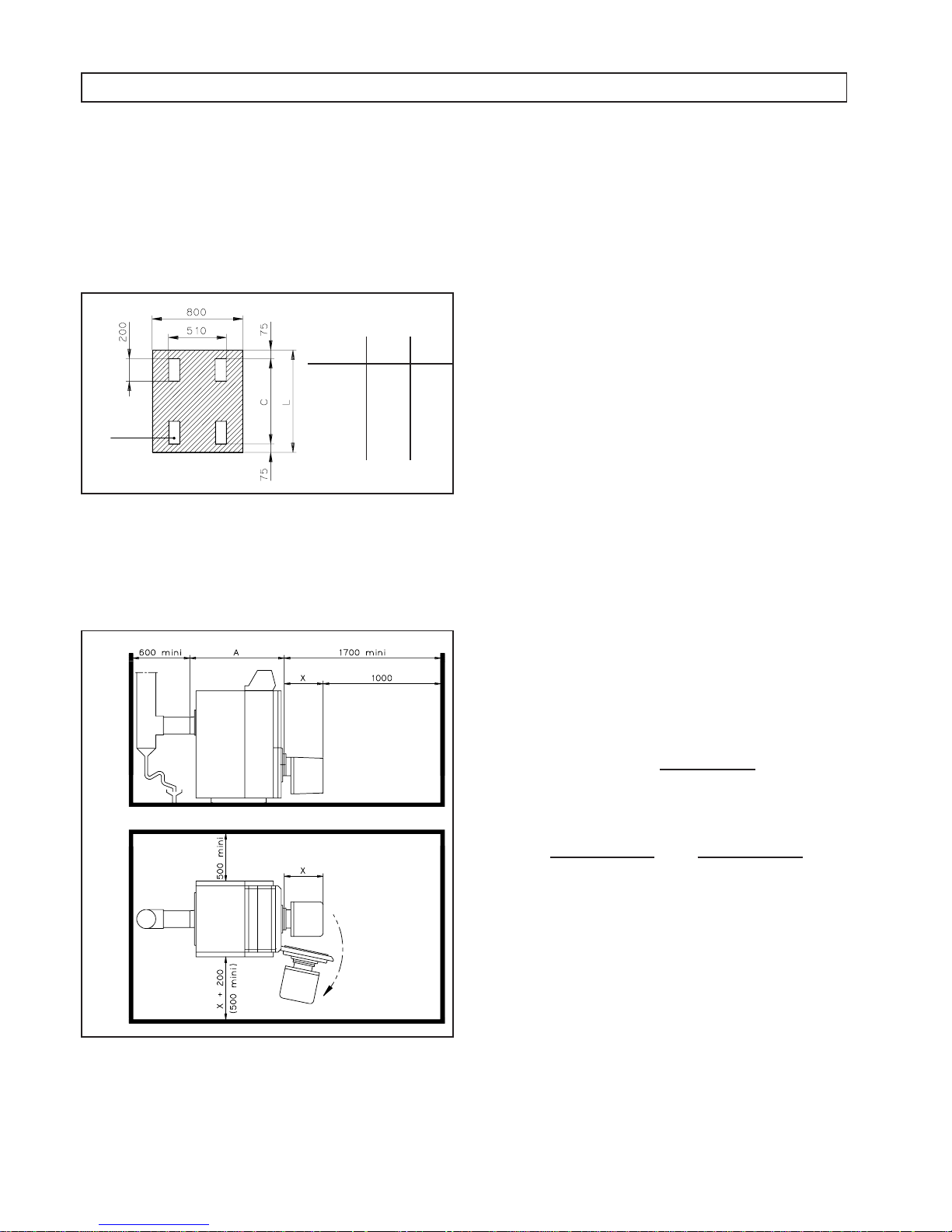
3 . 1 Boiler room layout
Plinth (see fig. 2)
No special plinth is required for this type of boiler. A simple dry
base suffices. For information, we provide the dimensions of
this dry base (figure 2). For certain special installations, a
sound-proof plinth may be necessary. We recommend a
metal plinth resting on reachable antivibration pads.
Fig. 3
Clearance (see fig.3)
The dimensions shown are minimal values which allow proper
access for assembly and maintenance operations.
No need to leave clearance above for cleaning purposes.
Boiler
size C L
34 750 900
35 920 1070
36 1090 1240
37 1260 1410
38 1430 1580
39 1600 1750
Flat bars
width 150
Optional
sealing
Fig. 2
Caution : assembly and installation must be carried out by a qualified engineer.
PN kW x 0,86
15K
PN kW x 0,86
5K
PN kW x 0,86
45K
and
N0225100.PLT
N0218601.PLT
Choice of burner
The burner should be chosen according to the boiler power
and furnace.
Ventilation
Comply with statutory regulations for low and high ventilation
6Ref. : CH - 1249 - A - 2
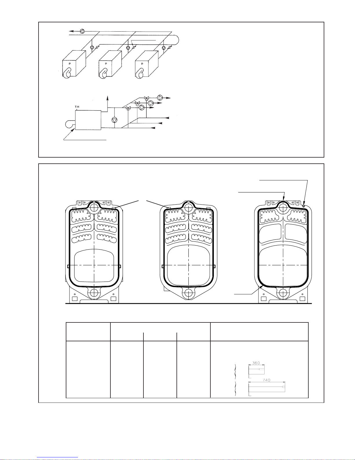
Boiler Number of sections
ref. Front Middle Rear
34 1 2 1 None
35 1 3 1 None
36 1 4 1 Short
37 1 5 1 Short
38 1 6 1 Long
39 1 7 1 Long
Distributors
Cord
S
S
E
Fig. 5
Sludge flush
Non return valve
Fig. 4
DIAGRAM OF THE ELEMENTS
S : tightening markings
E : spacing pads
S
Front Middle Rear
Assembly marking
Cord junction point
SSS
Minimum flow rate must be provided at all times,
whatever the rate of operation, either :
- by means of the main flow pump, provided that the
system has no mixing valve between each boiler and
the pump, and that the pump operates continuously,
- by means of a recycling pump or a loading pump
operating permanently.
In the case of a recycling pump or a loading pump per
boiler, and to avoid parasitic flows in the other boilers,
position non return valves upstream from the return
connection.
The burner must be controlled by the recycling or
loading pump. It can only be put in operation if the pump
operates. Secondarily, a flow control device, combined
with the TH thermostat, can be mounted on the return
of the boiler, downstream from the recycling or loading
pump.
To vents
00306N0225200.PLT
N0226701.PLT

7 Ref. : CH - 1249 - A - 2
3 . 2 Assembling the sections
The sections are assembled using nipples. For a good
tightness of the assemblies, it is compulsory to use a special
product which ensures a perfect seal (this coating is always
provided with the boiler).
Proceed in the following way:
1) Open the "Extra accessories" box,
2) Clean the nipples with a solvent,
3) Put the rear section in vertical position and secure it
against tilting by propping it up,
4) Position the wooden block provided in the "extra
accessories" box, 40 mm thick, in front of the rear
section’s legs,
5) On the vertical section, clean the groove awaiting the
cord with a metal brush, then position the cord
without stretching it, with the junction point at the top
(see figure 6) on the axis of the nipples line.
Cut the cord carefully.
6) Clean carefully with solvent the receiving surfaces. If
need be, use extra fine emery paper in case of rust
stains or small barbs.
Fig. 6
Assembly marking
Leaktightness cord
junction point
Place the cord in the
vertical element's
ream
BE CAREFUL TO ASSEMBLE THE MIDDLE SECTIONS CORRECTLY
Tightening of the
leaktightness cord
7) NEVER USE OLD NIPPLES.
Coat nipples and reams with the product provided,
using a clean brush.
8) Place the nipples in the vertical section’s orifices and
drive them in slightly using a piece of wood on which
to hit with a hammer or a mallet so as to maintain the
nipples in the reams. Do not drive them in too much, so
that the final tightening shall be obtained by bringing the
sections together.
Take care that the nipples be perfectly vertical, as a
deviation during tightening can break the section,
9) After having cleaned the middle section and applied the
coating, bring it on the block to place it facing the
vertical rear section and respecting the orientation of
the assembly marking which must be always oriented
towards front (see figure 6).
Drive it onto the two nipples using a mallet or a piece of
hard wood, hitting alternately, at top and bottom, facing
the nipples to ensure temporary assembly of the two
sections,
10 ) Ensure that they are perfectly vertical, and tighten it as
explained in the following chapter.
Assembly marking
Inside
Outsise
Wooden block (provided)
02244-01
N0224600.PLT

8Ref. : CH - 1249 - A - 2
3 . 3 Tightening the sections
To tighten the sections, a set of assembly bars is necessary.
It comprises:
For 4- to 7- section boiler:
- 2 assembly bars, length = 1.60 m (A),
- 2 fixed plates with stop-ring (B),
- 2 mobile plates with ball nut (C),
- 1 ratchet wrench.
This set is not part of normal supplies.
For 8- and 9- section boilers:
- Same as above,
- 2 bar extensions, length = 950 mm.
Or PARCEL N° 1 + PARCEL N° 2
1) Withdraw the plates’ alignment screws,
2) Place an (A) installation bar in each row of nipples,
3) Mount, on each bar, at the rear, a plate with (B) stop-
ring,
4) Mount at the front the (C) plates with tightening nut,
after having lubricated the thread,
5) Align the plates,
6) tighten the screw alternately by 1/2 a turn each, taking
care to avoid fan assembly.
Proceed with tightening until the sections touch, and
check it by looking in the firebox and the upper
"flue-ways".
Fixed plate B
Nbr. of elements
4 to 7
8 to 9
Bar
A
A + D
L dimension
1600
2550
l dimension
1355
2305
l max.
L
121 Run = 245 160 Step = 190
assembly bar A
Extension D
Nut Mobile plate C
54 70
Take alignment screws off
Stopring
Fig. 7
Fig. 8
Wrench
MID
section
Nut
C
Assembly
marking
Assembly
marking
A
B
Stop-ring
REAR
section
7) Assemble the other sections (1 by 1) in the same way,
while moving the wooden blocks alternately as you go
towards the front,
8) Do not loosen the assembly bars and position the 4
assembly linkages. Tighten them properly, leaving an
equal length at each end to secure the casing’s cross
members, and if necessary the adjustable legs,
9) Loosen and take the installation bars off,
10 ) proceed with the boiler assembly.
NOTE: If it were necessary to dismantle one of the
boiler’s sections, and to avoid damaging the
leaktightness gorges, it is imperative, when dismantling
the sections, to place the chisel at the level of the
spacing pads (E) provided in the upper part (see
figure 5).
FRONT
BACK
Positioning aid
N0219800.PLT
N0219700.PLT

9 Ref. : CH - 1249 - A - 2
EXCHANGER
5 Sealing cord Ø 7
40 Screws bag
Fig. 9
14 Disriburor, Length 180
14a Distributor, Length 530
15 Flow and return manifold
16 Drain valve
17 Sensor pocket, Length 100 mm
18 Upper baffle
18a Lowe baffle
19 Smoke box Ø 180
19a Smoke box Ø 200
20 Flue-way hatch (L)
20a Flue-way hatch (R)
21 Leaktightness braid Ø 8
22 Chamber door
23 Internal insulation
24 External insulation
25 Sight flange
26 Sight glass and seal
27 Door seal Ø 16
28 Burner plate
29 Burner plate gasket
30 Cleaning access. door
31 Internal insulation
32 External insulation
33 Insulation body blanket
39 Cleaning brush
40 Screws bag
41 Complete adjustable leg
1 Front section
2 Middle section
3 Rear section
4 Nipple Ø 89
5 Sealing cord Ø 7
6 Tie-rod
7 Reducer
8 Sensor pocket, Length 200 mm
9 Door hinge
9a Door hinge
10 door guide
11 Door pin
12 Welding flange
13 flange gasket
02236-00

10Ref. : CH - 1249 - A - 2
Method
• Assemble the 8 studs 12 x 65 around the rear section’s start and return orifices.
• If necessary, insert the distributor (see figure 22) in the return orifice by interpolating the seal
(13).
• Place the boiler in its final position and level it, which would be made easier by the "Adjustable
legs" option (chapter 3 . 1)
• Screw the pocket and the reducer (7) in a leaktight manner in the front section’s upper orifice.
• A threaded orifice Ø 2" is provided at the bottom of the front section, for mounting a valve
enabling rinsing and flushing of the installation’s sludge (we recommend mounting coil, a 90°
bend and the valve). A pre-cut space allows for passing the tubing in the casing’s lower
panel.
• Mount a drain valve tightly (not provided) on the installation or in the lower part of the rear
section using a reducer (not provided).
• A drain valve Ø 3/4" is delivered with the "Connection sleeves" option (see chapter4 . 2).
• Connect the flanges on the installation’s tubing, than fasten them on the boiler, interpolating
the seal (13), with 4 HM 12 nuts and 4 washers for each.
• After having checked the connections, proceed slowly with filling the installation, ensuring all
the air is vented, then proceed to the hydraulic test ((1.3 x P. operation) to check all leaktight
areas.
• Screw the shortest threaded part of the 4 studs M 8 x 40 in the rear section in the upper part.
• Check that the leaktightness braid (21) is in place.
• Engage the smoke box on the studs and fasten it (4 HM nuts and 4 washers) by tightening
the nuts moderately and simultaneously.
• Connect the boiler to the stack in the most direct possible manner and without reduction of
the size of the smoke duct. Ensure that the latter is leaktight.
• Insert the assembled baffles (18) in the upper "flue-ways" and, if need be, the simple baffles
(18a) in the lower "flue-ways" (see chapter 4 . 3).
• Screw the small threaded part of the 8 studs M 8 x 40 in the front section following the
indications of figure 10.
• Define the opening side for the doors.
• Mount the hinges (1 screw HM 10 x 30 + 1 nut HM 10 + 2 washers L 10 for each guide). The
door guide is located opposite the hinges, in the upper part.
• Depending on the chosen opening side, secure the hinge (9a) on each door using 2 screws
HM 12 x 35 + 2 washers M 12.
Caution: For reasons of practicality, it is recommended to mount the firebox door first.
• Mount the doors on the hinges using the axes (11).
• Engage the doors on the studs and fasten them (4 nuts HM 10 and 4 washers L 10 for each
door), tightening the nuts lightly and simultaneously.
• Depending on the size of its fixation, the burner is mounted directly on the door, or via a
perforated plate (see figure 11). Mount the burner plate (4 screws HM 12 x 35 + 2 washers
M 12) on the chamber door, interpolating the leaktightness seal (29).
- A plain plate may be provided on request.
3 . 4 Operational assembly diagram
Operation
Open the "chamber accessories" parcel
Distributor (14 - 14a)
Installing the boiler
Sensor pocket (8)
Sludge flushing
Drain valve (16)
Welding- flange (12)
Filling and hydraulic test
Smoke box (19 - 19a)
Stack
Optimizing baffles (18 and 18a)
Door hinges (9)
Door guide (10)
Door hinge (9a)
Chamber (22) and
Cleaning door (30)
Burner plate (28)

11 Ref. : CH - 1249 - A - 2
Top insulation blanket
Bottom insulation blanket
Insulation positioning
Fig. 10
Stud M 10 x 90
Hinge
Stud M 10 x 90
Stud M 10 x 90
Stud M 10 x 90
Screw TH M 10 x 30
Screw TH M 10 x 30
Screw TH M 10 x 30
Screw TH M 10 x 30
Hinge
Hinge
Hinge
Guide
Guide
Door hinge and door guide
assembly
Pre-drilled
burner door
Fig. 11
Fig. 12
Screw TH M 10 x 30
Stud M 10 x 90
Stud M 10 x 90
Screw TH M 10 x 30
Stud M 10 x 90
Stud M 10 x 90
4 holes M 8 equidistant on a perforation Ø of 170
4 holes M 10 equidistant on a perforation Ø of 200
4 holes M 14 equidistant on a perforation Ø of 254
Side insulation
blanket
Rear insulation
blanket
N0226400.PLT
N0225600.PLT
N02187-01.DSF
Front insulation blanket
Front

12Ref. : CH - 1249 - A - 2
Method
• Screw the hexagonal spacers on the rear section’s 3 spacer pads, and place on each
spacer a TH M 5 x 10 screw.
• Place the lower heat-insulator (cross-shaped, 50 mm thick on black veil) under the
heat chamber taking care to jam the ends between the assembly linkages and the
chamber.
• Casing the whole of the chamber by the side insulation (50 mm thick) and tuck
its ends under the chamber (see figure 12).
• On the rear section, insert insulation (100 mm thick) on the spacers.
• NOTE : for exchangers with 8 or 9 sections, the side insulation is supplied in 2 parts
to be positioned side-by-side, the large part towards the front.
• Engage the lower rear on the three spacers and secure it by tightening the 3 screws.
• Mount both lower feet on the front section (2 screws HM 8 x 16).
• Mount the cross sections on the assembly linkages, fasten them using the counternuts HM 12. The front cross-member is provided with a protection clip (110 mm long)
with a plastic collar and a NUT nut.
• Laterally secure the side rails on the cross-members using bolts HM 8 x 16 (square
hole to the front).
Front
Middle
Rear
Nb. of elements
7
300
510
514
8
300
510
684
9
300
510
854
A
C
B
6
300
854
5
300
684
4
300
514
Operation
Open the "casing" parcel
Rear spacer (50)
(see figure 15)
Body insulation blanket (33)
(see figure 12)
Lower rear (51)
Lower foot (52)
Cross-member (53)
Right side-rail (54)
Left side rail (55)
3 . 4 Operational assembly diagram (continued)
Fig. 13
Fig. 14
Rear
Front
Rear Middle
Front
A B A C B
Casing sides assembly Front casings assembly
N0220900.PLT
N0221000.PLT

13 Ref. : CH - 1249 - A - 2
CASING ASSEMBLY
50 Rear spacer
51 Lower rear
52 Lower foot
53 Cross-member
54 Right side-rail
55 Left side-rail
56 Lower mask
57 Right side
58 Left side
59 Side restraint
60 Rear right side
61 Rear left side
62 Middle side
63 Upper rear
65 Front top
66 Rear top
67 Middle top
68 Upper front
69 Lower right front
70 Lower left front
71 Casing screw bag
71 Casing screw bag
Fig. 15
02237-01.TIF

14Ref. : CH - 1249 - A - 2
Operation
Lower mask (56)
Front sides (57 - 58)
Side restraint (59)
Middle sides (62)
Rear sides (60 - 61)
Upper rear (63)
Upper heat-insulator (33)
Front top (65)
Middle top (67)
Rear top (66)
Control panel
Lower left and right façades
(69 - 70)
Upper façade (68)
(see figure 14)
Method
• Place the lower mask on both lower feet at the front of the boiler (this part is pre-cut
to allow passing of sludge tubing, or can also be taken out)).
• Hook the front sides onto the side-rails and fasten them using the axis screws (Ø 8)
in the upper part and at the bottom using a TH M 5 screw on the lower foot.
• Extract the restraint from the side panel by tilting it, insert it in the side heat-insulator’s
slit, and hook it on the assembly linkage; Tighten the axis screw.
• (only for boilers with 7, 8 or 9 sections)
• Put the middle side on the side-rails. Slide it so that the axis of the restraint enters the
orifice provided.
• Extract the side restraint in the same way as for the front side.
• Put the rear side on the side-rails, and slide so that the side’s return fold casings the
lower rear (51) “s fold and the axis of the restraint enters the orifice provided.
• Secure the rear sides on the lower rear using 4 HM 5 x 10 screws.
• Pin the upper rear on the sides and click it in downwards in the keyhole slots provided
for this purpose.
• Place the upper heat-insulator on the side-rails (slit at the front).
• Place the front top on the side axes and push it forwards to bumper.
• (only for boilers with 7, 8 or 9 sections)
• Place it on its axes and push it forwards until it joins up with the front top.
• Place it on its axes and push forwards until it joins up with the front or middle side in
the case of a boiler 7, 8 or 9 sections.
• Secure it on the upper rear (2 HM x 10 screws).
• Assemble the control board as indicated on this page.
• Click the faþades in laterally and downwards on the buttons fastened on the sides’
folds.
Locking is done by the central feet.
• Engage both axes in the lower faþades’ holes.
• Press the façade on the sides.
- fit the control panel on the front top while routing the
probe cables through the opening included to this
effect
- engage the pins under the panel into the slots, and
pull the control panel towards you.
- Lock it using the 2 plactic pins (A) and the M5 screw
(B) on the top front
CONTROL PANEL ASSEMBLY
N04214DSF
Fig. 16
plastic pins
A
Probe cables
B

15 Ref. : CH - 1249 - A - 2
BOILER AND BURNER POWER SUPPLY
Fig. 20
Three-phase
current
Single-phase
current
Single-phase
current
CABLES FITTING
Fig. 21
Control
Control
Burner motor
power supply
CAUTION :In the case the burner motor is supplied with
three-phase power, control panel single phase supply
must imperatively be taken from one of the phases
supplying the burner motor.
VERY IMPORTANT : Never connect the burner control box
directly to one of the phases.
N0225300
ELECTRIC CONNECTION
The facility must comply with currently enforced national and
local regulations.Notably, the electric connection of the boiler
requires a sectioning device on each pole with a minimum 3
mm distance between each contact.
For the complete electric connection of the various
types of control panels, refer to the manual specific to
the panel.
The power supply connection terminal strip is accessible after
removing the cover at the back of the panel. It is located in the
lower right corner seen from the back.
Connect the phase to the strip’s L terminal.
The line must be able to withstand an intensity of 6.3A under
230V 50 Hz + Ground (check whether the power of the
pump(s) is compatible).
Apply the electric connection as per the electric diagram in
the instructions. Plan a grounding wire exceeding by 50 mm
in length to the neutral and phase wires for tearing safety.
The burner switch located on the control panel does not
dispense from installing the regulatory wall switch.
In the case of insufficient ionising current due to non compliant
neutral or ground, we recommend adding a circuit isolation
transformer with a power at least equal to 600 VA.
Control panel supply connection terminal strip
The ground socket planned on the connecting terminal strip must be connected as per currently enforced
provisions.
03935-00
Main power supply
230 Vac 50 Hz
(phase imperatively in L)
shunt "UV"
Boiler glove finger
withoud regulation probe
When fitting the capillaries, ensure they are inserted fully
in the glove finger.
1 - Overheating safety thermostat
2 - Heating outlet thermometer
3 - Regulation thermostat
4 - Tube Ø 6
5 - Heating regulation probe
3 - Regulation thermostat 2nd Stage
Boiler glove finger
with regulation probe
02078-01
00229-5
02078-05
2
CM control panel
CE, ECO 5E, ECO7E, ECO8E
control panel
CS control panel
6
Fitting the thermostat bulbs, thermometer (and regulation
probe in option) in the glove finger as shown in the diagram.
Capillaries
Burner
cables
Clamp-
nut A
Earthing
wire
Front
crosspiece
AV
Lower piece
N04156.DSF

16Ref. : CH - 1249 - A - 2
4. INSTALLING THE OPTIONS
4 . 1 Adjustable legs
For levelling the assembled heating chamber, located in the boiler room.
Assembly of the 4 heating chamber legs:
- Screw the adjusting screws up to the maximum in the supports,
- Engage the support in the space provided on each heating chamber leg, as shown in figure 19. Fasten the supports on
the end of each assembly linkage (nut + washer),
- Slide the pads under the adjusting screws,
- Level using the screw with a 17 flat wrench (adjusting travel = 16 mm maximum).
15 - Return manifold
16 - Drain valve
17 - Sensor pocket
12 - Flange
13 - Gasket
14 - Distributor
4 . 2 Heating system flow and return connection manifolds with drain valve and Sensor
pocket for remote control
Boiler leg
Support Support fixation
nut
Pad
Wrench
Fig. 19
Fig. 20
Adjusting
screw
The manifolds move the main heating system connection
outside the casing. They are provided with threaded orifices
for fitting the following accessories:
- On Ø 1/2" start and return: pockets (17) for remote
control sensor,
- On Ø 3/4" flow: drain or safety accessories (not provided),
- On Ø 3/4" return: drain valve (16);
Mount the manifolds (see figure 20) on the boiler’s flow and
return orifices, positioning the threaded orifice Ø 1/2" towards
the exchanger, placed on top for flow and on the side for return.
NOTE: For boilers fitted with a water distributor (14) on the
return, the distributor must penetrate as far as possible in the
exchanger return orifice.
Its fixation flange will be placed, between two joints (13),
between the return manifold and the rear section.
Heating system’s connecting flanges (12) should be welded
to the water system’s pipes before fitting on the boiler.
N0223000.PLT
02244-00

17 Ref. : CH - 1249 - A - 2
Ø 7,5
Upper baffles
Lower baffles
4 . 3 Lower savers
The two optional extra optimizing baffles should be placed in
the two lower "flue-ways" as shown in figure 21:
Engage each baffle in the "flue-way".
Performance as shown in the characteristics table corres-
pond to the boiler operating with the upper and lower baffles
as shown in the position diagram opposite.
Fig. 22
Fig. 21
4 . 4 Control panel options
Before any operation inside the control panel, disconnect
power supply using main switch located on heating system
general control board.
Flue gas thermometer :
Its housing is to be positioned on the control panel front and
the bulb on the flue stack.
- Take off the top, open panel front
- Take off the factory-mounted blank plate and engage the
capillary and the thermometer housing into the front aperture
- Guide the capillary through control panel rear and casing
front top, parallel to the other installed capillaries. Direct
the capillary towards the back of the boiler, on exchanger
insulating blanket, in order to be able to bring its bulb up
into the connection pipe between flue hood and stack
- Drill, preferably vertically, the fluegas duct to + 7.5 and
drive the bulb holding clip (see fig. 22)
- Engage the bulb into the clip. Close the control panel and
fit top again.
Burner cables :
The 1st stage burner cable with a 7-contact connector and the
2nd stage burner with a 4-contact connector are to be
connected on the terminal block inside "B" control panel,
markings being properly aligned. guide the wires as explained
in the ñ of page 15.
Flue
stack
Holding
clips
Bulb
N0221000.PLTN224200.PLT

18Ref. : CH - 1249 - A - 2
5 - 1 Filling
- Water quality for the heating system
Avoid using hard water, which may scale the boiler. If TH
or total hardness is above the French 25°, the boiler
should be filled with softened water.
- Filling the boiler and heating system
While filling, which must be done slowly, ensure that the
stop valves are open and that the mixing valve can be 1/
2 open.
The automatic drain cock plug, normally fitted on the
boiler outlet, must remain untightened in order to achieve
continuous draining during filling-up. Drain all high points
of heating system and close the various draining screws
one after the other as soon as water reaches their level.
After filling the boiler for the first time, flush completely
(using the sludge flushing valve) in order to get rid of
foreign bodies that may come into the components or the
pipes during assembly.
- Water topping up
Subsequent boiler topping-up should be practically nonexistent and in all cases controlled and registered by a
water flow meter. Frequent topping-up is the a symptom
o f a leakage which should be repaired as soon as possible.
5 - 2 Preliminary checks
When commissioning the boiler for the first time in the
season, or after a prolonged shutdown period :
- ensure that filling was done properly and check overall
tightness. If necessary, put more water and drain all high
points until water flows slightly.
- check the connection of the flue stack and the proper
working condition of the draught regulator if any
- check that the high and low vents are not obstructed
- ensure that the doors and the flue access plates are
closed and tight
If necessary, act upon the tightening points.
- ensure that the burner is properly locked
- check if it is properly supplied in fuel, that supply and
return valves are open
- for operation with gaseous fuel types, check that the
safety conditions are fulfilled.
Note : After starting up a system for the first time, it is
recommended to clean the pump filter in the case of oil firing,
or the line filter in the case of gas firing.
After a few hours of operation, check the tightness of the
doors. If necessary, tighten their fastening nuts.
5. COMMISSIONING 6. MAINTENANCE
Boiler
Check water pressure on pressure gauge and, if necessary,
restore normal pressure. Only perform this operation when
the system is cold. If frequent topping-up is necessary, there
is a leak in this case, notify the installer. Never draw water
from the heating system. In order to avoid slow but steady
sooting, harmful to proper boiler operation, it is recommended
to clean it regularly twice a year at least.
This is always done with the boiler stopped and the power
supply cut out.
Proceed as follows :
• put ON burner switch located on the control panel as well
as the main boiler room switch
• remove casing front panels
• open the cleaning door and the chamber door and take
the flue-way hatches away.
• take the optimizing baffles down and brush them.
• clean the walls of each flueway with the brush provided
with the boiler as well as the combustion chamber walls.
• remove soot and combustion deposits, if possible using
a vacuum cleaner
• Clean the inside of the smoke hood
• the lagging material of the doors may be brushed with a
soft brush. Do not use a metal brush. Be careful not to
damage the seal.
• once the cleaning is over, put the hatches back up on
the smokebox, put the optimizing baffles back in their
respective "flue-ways", close the chamber and cleaning
doors, ensuring that they are tight.
• set casing front panels back up.
Sludge
This sludge, due to corrosion in the system, travels inside the
pipework and makes up deposits in the boilers. We
recommend to rinse the boiler efficiently and thoroughly
and check the flushed water quality.
Burner
The burner should be submitted to regular maintenance. See
special instructions, provided with the burner. If necessary,
contact the retailer or manufacturer of the burner.

19 Ref. : CH - 1249 - A - 2

20Ref. : CH - 1249 - A - 2
PRINTED AT SOISSONS FACTORY - FRANCE
157, Avenue Charles Floquet
93158 Le Blanc-Mesnil - Cedex
Téléphone : + 33 (0)1 45 91 56 00
Télécopie : + 33 (0)1 45 91 59 50
www.chappee.com
S A au capital de 43 214 640 €
RCS Bobigny B 602 041 675 A.P.E 282 D
 Loading...