

SPREADERS Assembly / Operation Instructions / Parts
Go to www.
chapinmfg.com
for Details
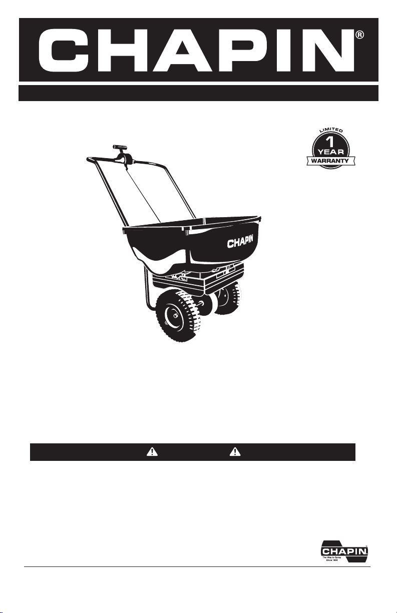
Model 8003A
70 lb. Spreader
DO NOT RETURN TO THE STORE.
Please call 800-950-4458 if you are missing any parts, having trouble assembling,
or have any questions regarding the safe operation of this product.
WARNING
Carefully Read These Instructions Before Use
IMPROPER USE OR FAILURE TO FOLLOW INSTRUCTIONS CAN RESULT IN PRODUCT FAILURE
OR INJURIES. FOR SAFE USE OF THIS PRODUCT YOU MUST READ AND FOLLOW ALL
INSTRUCTIONS BEFORE USING.
MODEL 8003A
CHAPIN INTERNATIONAL, INC. P.O. BOX 549 700 ELLICOTT ST. BATAVIA, NY 14021-0549 www.chapinmfg.com 800-950-4458
015785 R0318
ASSEMBLY INSTRUCTIONS
Suggested Tools:
• Wrench and/or Ratchet Set
• Pliers
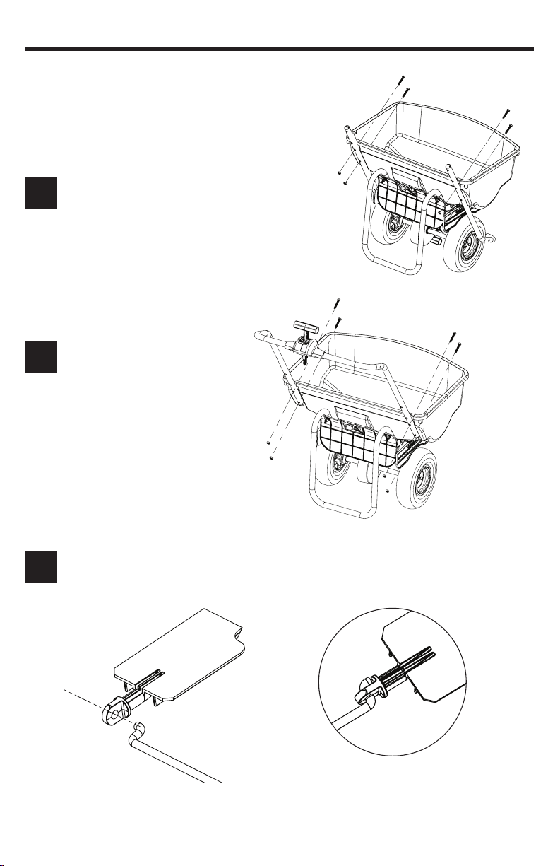
Remove the handle from the hopper (4 nuts and bolts).
Note: the gate linkage is nested between the hopper and
1
the frame for shipment.
Flip handle upright and reattach
handle to hopper using the 4 nuts
2
and bolts from step 1.
Assemble the gate linkage to the gate by inserting the “S-shaped” end into the gate.
Note: Let the linkage hang freely - Gate will not stay attached until completely assembled.
3
Correct
Orientation
2E
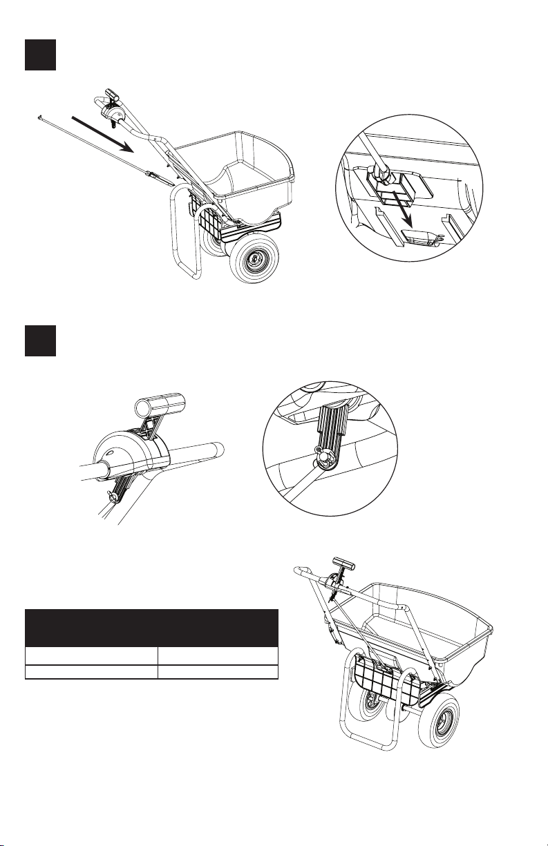
Slide the gate and linkage into the L ribs on hopper keeping linkage attached to the gate.
4
Insert the “L-shaped” end of the linkage into the gate control on the handle and secure with
5
the cotter pin provided. Using pliers bend cotter pin to secure linkage to the gate control.
MATERIAL APPLICATION CHART
Particle Size/Material Spreader Setting
Calcium Chloride Pellets
Rock Salt
1-2
3-4
Completed Assembly
2E
General Operating Instructions
• Be sure gate control is in the closed position before lling hopper
• Determine appropriate setting for material being used by reading the suggested setting on the
material’s bag AND/OR by referencing the application chart on your spreader’s control panel
(Charts provided are only guidelines. Be sure to read the instructions on the bag/box of the
material you’re spreading to identify accurate setting needed)
• Remove wing nut and slide indicator to desired setting. Tighten wing nut completely.
• To begin spreading, start walking (about 3mph pace) release the control lever by pushing it
forward. It will spring forward to the slide stop.
• To stop spreading simply pull the gate control back into the closed position.
Storage and Maintenance
• When nished spreading empty hopper of any remaining material
• oroughly wash spreader and allow to dry before storing
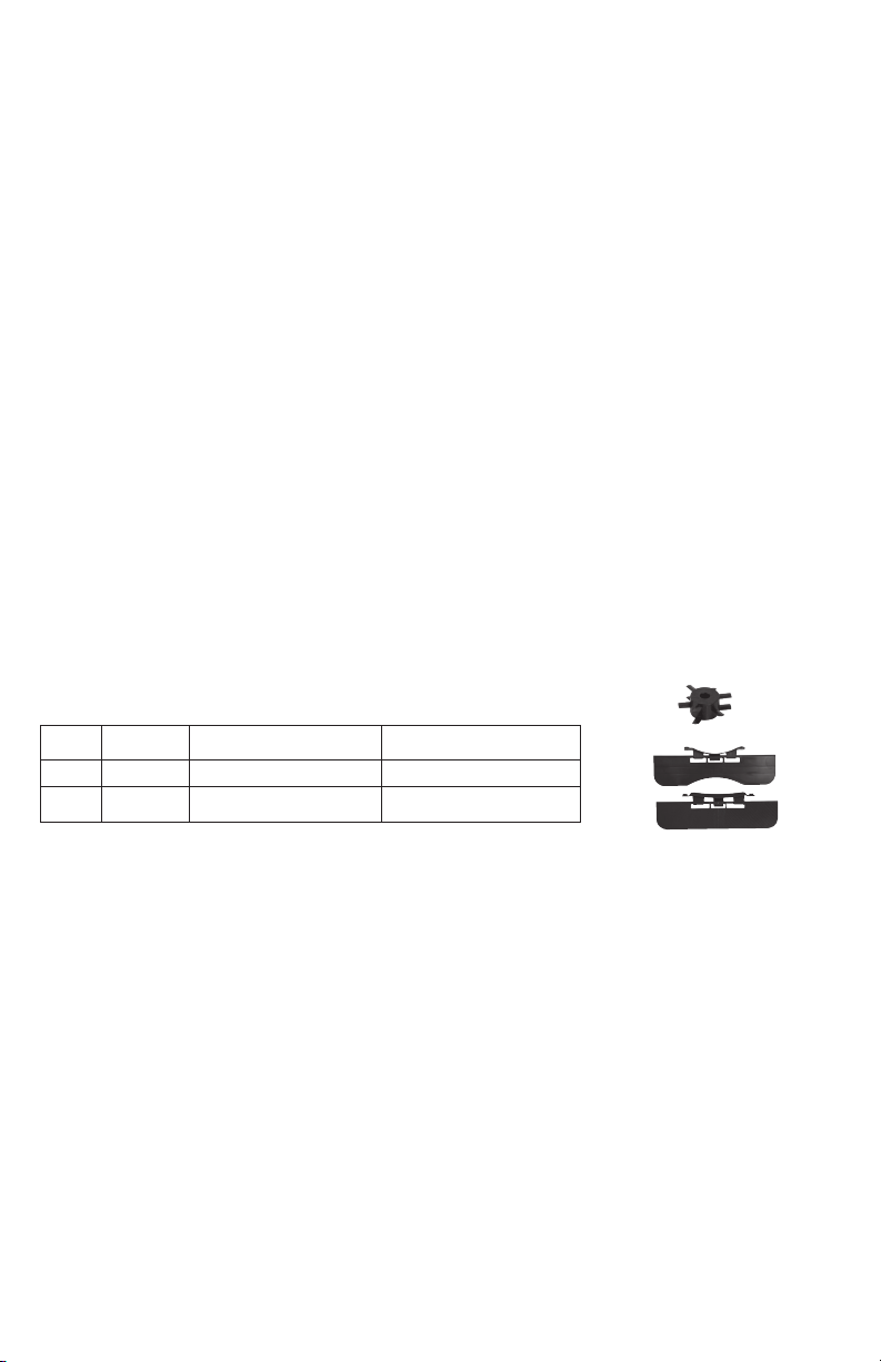
Replacement Parts
Ref.# Qty Part No. Description
1 1 6-9067 Auger
2 1 6-8280 Baffle Kit
CHAPIN CUSTOMER SERVICE: 800-950-4458 www.chapinmfg.com
CHAPIN INTERNATIONAL, INC. P.O. BOX 549 700 ELLICOTT ST. BATAVIA, NY 14021-0549
Due to our ongoing product improvement process, product specifications may change without notice. U.S. and foreign patents pending.
2
1

ESPARCIDORA Armado / Operación Instrucciones / Partes
Visite www.
chapinmfg.com
para conocer más
detalles.
Model 8003A
70 lb. Spreader
NO LO REGRESE A LA TIENDA
Por favor, llame al 800-950-4458 si le faltan piezas, tiene problemas con el ensamblaje o tiene alguna duda
sobre el funcionamiento seguro de este producto.
ADVERTENCIA
Lea estas instrucciones atentamente antes de utilizarlo
EL MAL USO O EL NO SEGUIR LAS INSTRUCCIONES PUEDE ORIGINAR QUE EL PRODUCTO NO
FUNCIONE O QUE PRODUZCA LESIONES. PARA UN USO SEGURO DE ESTE PRODUCTO, DEBE
LEER Y SEGUIR TODAS LAS INSTRUCCIONES ANTES DE UTILIZARLO.
MODEL 8003A
CHAPIN INTERNATIONAL, INC. P.O. BOX 549 700 ELLICOTT ST. BATAVIA, NY 14021-0549 www.chapinmfg.com 800-950-4458
015785 R0318

INSTRUCCIONES DE MONTAJE
Herramientas sugeridas:
• Juego de llaves o trinquetes
• Pinzas
Retire la manija de la tolva (4 tuercas y pernos).
Nota: el enlace de la compuerta está anidado entre la tolva
1
y el marco para el envío.
Gire la manija hacia arriba y colóquela
de nuevo en la tolva usando las 4
2
tuercas y pernos del paso 1.
Ensamble el enlace de la compuerta a la misma insertando el extremo en forma de “S” en ella.
Nota: deje que el enlace cuelgue libremente: la compuerta no permanecerá conectada hasta que
3
esté completamente ensamblada.
Orientación
correcta
1S

Deslice la compuerta y el enlace en las ranuras en “L” de la tolva manteniendo el enlace
4
unido a la compuerta.
Inserte el extremo en forma de “L” del enlace en el control de la compuerta en la manija y
5
asegúrelo con el pasador de aletas provisto. Con las pinzas, doble el pasador de aletas para
asegurar el enlace al control de la compuerta.
CUADRO DE APLICACIÓN DE MATERIAL
Tamaño/material de las partículas Conguración de la esparcidora
Partículas de cloruro de calcio
Sal de roca
1-2
3-4
2S
Ensamblaje Completo

Instrucciones de funcionamiento general
• Asegúrese de que la compuerta de control esté cerrada antes de llenar la tolva
• Determine la conguración adecuada para el material que se utiliza leyendo la conguración sugerida
en la bolsa del material O dirigiéndose a la tabla de aplicación en el panel de control del esparcidor
(Las tablas provistas son solo referenciales. Asegúrese de leer las instrucciones en el empaque del
material que está esparciendo para identicar la conguración necesaria correcta)
• Quite la tuerca mariposa y deslice el indicador hacia la conguración deseada. Ajuste las tuercas
mariposa por completo.
• Para comenzar a esparcir, empiece a caminar (a un paso de 3 mph o 4.5 km/h) y libere la palanca de
control empujándola hacia adelante. Se deslizará hacia adelante hasta el tope.
• Para dejar de esparcir simplemente jale el control de la compuerta a la posición de cerrado.
Guardado y mantenimiento
• Cuando termine de esparcir, quite cualquier material restante de la tolva
• Lave el esparcidor por completo y déjelo secar antes de guardarlo
Partes de repuesto
Ref.# Qty Part No. Descripción
1 1 6-9067 Taladro
2 1 6-8280 Kit deflector
CHAPIN CUSTOMER SERVICE: 800-950-4458 www.chapinmfg.com
CHAPIN INTERNATIONAL, INC. P.O. BOX 549 700 ELLICOTT ST. BATAVIA, NY 14021-0549
Due to our ongoing product improvement process, product specifications may change without notice. U.S. and foreign patents pending.
2
1

ÉPANDEUR Instructions d’assemblage/d’utilisation/pièces
Rendez-vous à
www.chapinmfg.
com pour les
détails
Modèle 8003A
70 lb. Spreader
NE PAS RAPPORTER AU MAGASIN
Veuillez composer le 800-950-4458 si des pièces sont manquantes, si vous avez des problèmes d’assemblage
ou des questions relativement au fonctionnement sécuritaire de ce produit.
AVERTISSEMENT
Lisez attentivement ces instructions avant l’utilisation
UNE MAUVAISE UTILISATION OU NE PAS SUIVRE LES INSTRUCTIONS PEUT MENER À UNE
DÉFAILLANCE DU PRODUIT OU À DES BLESSURES. POUR UTILISER CE PRODUIT SANS
DANGER, VOUS DEVEZ LIRE ET SUIVRE TOUTES LES INSTRUCTIONS AVANT L’UTILISATION.
MODEL 8003A
CHAPIN INTERNATIONAL, INC. P.O. BOX 549 700 ELLICOTT ST. BATAVIA, NY 14021-0549 www.chapinmfg.com 800-950-4458
015785 R0318

INSTRUCTIONS D’ASSEMBLAGE
Outils recommandés :
• Jeu de clés et/ou de cliquets
• Pinces
Enlevez la poignée de la trémie (4 écrous et boulons).
Remarque : la tringlerie de la vanne est logée entre la
1
trémie et le cadre aux ns d’expédition.
Faites basculer la poignée à la
verticale et attachez-la à nouveau
2
à la trémie à l’aide des 4 écrous et
boulons de l’étape 1.
Assemblez la tringlerie de la vanne à cette dernière en insérant l’extrémité « en S » dans la vanne.
Remarque : Laissez la tringlerie pendre librement - la vanne ne restera pas attachée jusqu’à ce
3
qu’elle soit entièrement assemblée.
Bonne
orientation
1F

Slide the gate and linkage into the L ribs on hopper keeping linkage attached to the gate.
4
Insert the “L-shaped” end of the linkage into the gate control on the handle and secure with
5
the cotter pin provided. Using pliers bend cotter pin to secure linkage to the gate control.
TABLEAU D’APPLICATION DU MATÉRIEL
Taille des particules/matériau Réglages de l’épandeur
Granulés de chlorure de calcium
Sel gemme
1-2
3-4
2F
Assemblage Terminé

Instructions générales d’utilisation
• Assurez-vous que le contrôle de vanne soit en position fermée avant de remplir la trémie.
• Déterminez le réglage approprié du matériel à être utilisé en vériant le réglage suggéré sur le sac du
matériel ET/OU en vous référant au tableau d’application sur votre panneau de contrôle de votre
épandeur (les tableaux fournis ne sont que des lignes directrices. Assurez-vous de lire les instructions
sur le sac/boîte de matériel que vous épandez pour dénir le juste réglage dont vous avez besoin)
• Retirez les écrous à oreilles et glissez l’indicateur au réglage désiré. Resserrez complètement les écrous
à oreilles.
• Pour commencer l’épandage, commencez à marcher (à une cadence d’environ 3 mph) et relâchez la
manette de commande en la poussant vers l’avant. Elle sera déclenchée vers l’avant jusqu’à l’arrêt de
la glissière.
• Pour arrêter l’épandage, tirez simplement sur le contrôle de la vanne en position fermée.
Entreposage et entretien
• Une fois l’épandage terminé, videz la trémie de tout matériel restant.
• Nettoyez soigneusement l’épandeur et laissez sécher avant d’entreposer
Pièces de rechange
Ref.# Qty Part No. Description
1 1 6-9067 Foreuse
2 1 6-8280 Kit de déflecteur
CHAPIN CUSTOMER SERVICE: 800-950-4458 www.chapinmfg.com
CHAPIN INTERNATIONAL, INC. P.O. BOX 549 700 ELLICOTT ST. BATAVIA, NY 14021-0549
Due to our ongoing product improvement process, product specifications may change without notice. U.S. and foreign patents pending.
2
1
 Loading...