

Chapin 62000 User Manual [en, es, fr]
DO NOT RETURN THIS
SPRAYER TO STORE
Call: 1-800-950-4458
www.chapinmfg.com
Tree / Turf ProTree / Turf Pro
Backpack
Use and Care Manual
Chapin International, Inc
P
.O . Box 549
700 Ellicott St.
Batavia, NY 14021-0549 U.S.A.
1-800-950-4458
www.chapinmfg.com
Model 62000 4.0G/15.1L
WARNING!
Carefully Read These Instructions Before Use
010805 R0510
WARNING!
IMPROPER USE OR FAILURE TO FOLLOW INSTRUCTIONS CAN RESULT IN
PRODUCT F
AILURE OR INJURIES. FOR SAFE USE OF THIS PRODUCT YOU MUST
READ AND FOLLOW ALL INSTRUCTIONS BEFORE USING.
WARNING: Handling the brass parts of this product will expose you to lead, a chemical
known to the State of California to cause birth defects and other reproductive harm.
Wash hands after handling.
CAUTION
RULES FOR SAFE OPERATION
Before assembling and operating your sprayer, read all instructions
thoroughly. When working with equipment under pressure, safety
precautions must always be carefully observed, including the following:
•
NEVER spray flammable materials or pressure and gas producing
chemicals.
6-8178
Assemblage
du c
ylindre
du piston
6-8179
Assemblage
du piston à
pompe
INFORMATION DE COMMANDE DE PIÈCES DE RECHANGE
Soupape
de plaque
Joint torique
Joint torique
Collier
6-8151
Régulateur
de pression
Plaque
portesoupape -
ylindre
c
du piston
6-8180
T
de pompe à piston
Collier -
pompe à piston
rousse de réparation
Joint torique -
c
Joint torique c
ylindre du piston
ylindre de pression
• ALWAYS read chemical label before filling sprayer as some chemicals may
be hazardous when used with this sprayer.
• ALWAYS wear goggles, gloves, a long-sleeve shirt, long pants, and full foot
protection when spraying. Work in a ventilated area or outdoors.
• PRE-USE CHECK: Before each use check tightness of hose nut to be sure hose is
securely attached to the shut-off assembly. Insure hose is securely attached to the tank
by tightening hose clamp if necessary. Insure that all nozzle and wand connections are
tight. Insure the large pump clamp is tight. Insure the 2 bolts used to attach the pump
lever to the pump shaft are tight.
• DO NOT leave a pressurized sprayer in the hot sun or anywhere near a heat source.
Heat can produce pressure to build up causing sprayer to ignite or explode resulting in
injury or death.
• NEVER pressurize sprayer by any means other than the original pump. Over
pressurizing can cause sprayer to explode resulting in injury or death.
• DO NOT attempt to modify or repair this product except with original manufacturer’s
parts.
NOTE: The tank and hose may have residual water in it due to quality
testing performed on the sprayer.
1E
Joint torique du coude Rondelle de boyau
Joint
d’étanchéité
de buse
Joint torique
du tube
6-8153
T
rousse de
joint torique
6-8182
Backpad et
Sangles
6-8146
anier du filtre et bouchon
P
6-8150
Pinces du tube
6-8501
CF V
alve™
Félicitations!
Vous avez acheté un produit de qualité Chapin.
Enregistrez dès que possible votre pulvérisateur en ligne à l'adresse suivante:
www.chapinmfg.com/warranty.asp
P. O. Box 549 700 Ellicott St. • Batavia, NY 14021-0549 U.S.A. • 1-800-950-4458 • www.chapinmfg.com
À cause de notre processus d’amélioration continue de produits, les spécifications de produits pourraient changer sans préavis. Brevets américains et étrangers en instance.
Chapin International, Inc
INFORMATION DE COMMANDE DE PIÈCES DE RECHANGE
ASSEMBLAGE DE BUSE
6-8096
Buse en
éventail
plat
Écrou de
blocage
Buse joint
d’étanchéite
Coude avec
joint torique
Joint
torique
Bouchon
vissé
Rondelle
de boyau
6-8148
rousse
T
de buse
6-8122
Buse de
laiton
ajustable
Tube
6-8169
T
rousse de
remplacement
6-8093
Buse poly
ajustable
6-8149
Assemblage
de tube
APPLICATIONS & USE FOR YOUR SPRAYER
Avoid using a sprayer for general cleaning purposes if plant protection or herbicide chemicals have already
been used in the sprayer. If a sprayer has been used for plant protection or as an
herbicide, clean the
sprayer completely (see page 5) before using.
Plant Food: Use different spray patterns for optimum foliage feeding or for fungicide and pesticide
application.
Herbicides: Reduce weeds and unwanted plants but avoid using the same sprayer for plant feeding or
protection without thoroughly cleaning (see page 5) the sprayer first.
General Household Use: Apply detergents, vinegar, cleaning solutions, warm water (do not exceed
120°F/49°C) or nontoxic household cleaning chemicals for carpets, floors, walls, glass, counter tops and
ceilings. DO NOT use sprayer that has been used with herbicides, pesticides or other toxic chemicals for
household applications.
General Outdoor Use: Use the sprayer for cleaning windows or with a detergent for general purpose
cleaning. Other applications include wood preservatives, waxes, water proofing, and diluted household
bleach (max. 1 part household bleach to 9 parts water solution).
SPRAYER COMPONENTS & USE INFORMATION
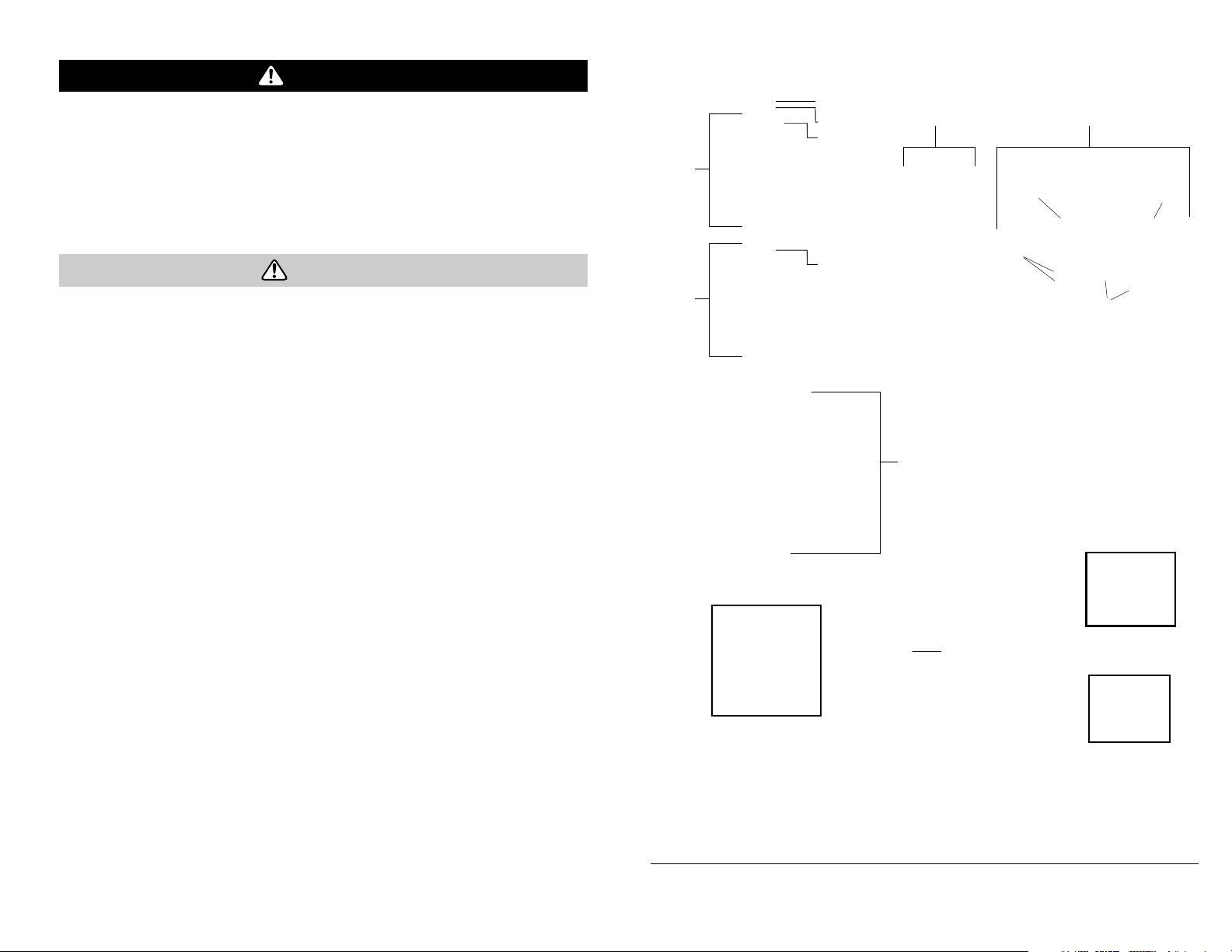
CF VALVE™ ASSEMBLY
Assemble nozzle gasket to inlet side of CF Valve™ and screw onto the
end of the elbow. Place the fan nozzle tip into the retaining nut and
then place the nozzle gasket on the fan nozzle tip flange. Screw this
Inlet
(3/8
Thread)
CF Valve™
(1.5 BAR-21 psi)
Outlet
(3/8 thread)
Fan
Nozzle
Tip
assembly onto the outlet side of the CF Valve™. To uninstall the CF
Valve™, reverse the above instructions.
The CF Valve™ is intended to be used with a fixed nozzle. The Fan
Elbow
Nozzle
Gasket
Nozzle
Gasket
Retaining
Nut
nozzle tip provided is rated @ .4 GPM @ 40psi.
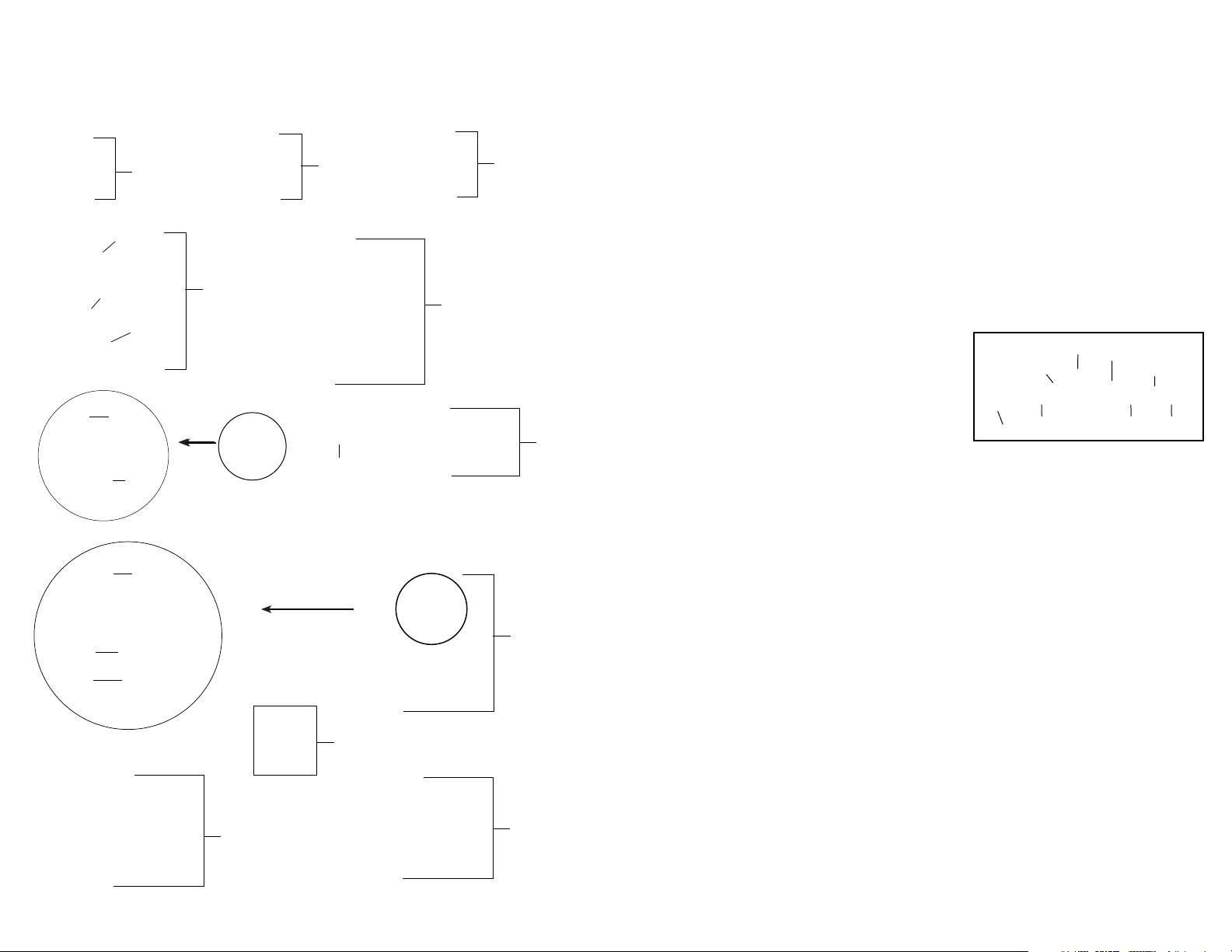
NOZZLE ASSEMBLY
Figure 1-2
Unscrew the nozzle cap
(1) from the nozzle body (3) with retaining nut (2) fastened tightly to the elbow
(5). Unscrew the retaining nut (2). Push the nozzle body (3) with the nozzle gasket (4) out of the
retaining nut (2). To reinstall the nozzle, reverse the above instructions.
Figure 3
Unscrew the retaining nut from the elbow and push the fan nozzle tip and gasket out of the retaining nut. To
reinstall the nozzle, reverse the above instructions.
Écrou de blocage
Boyau
6-8120B
Trousse de
réparation de
robinet d’arrêt
11F
6-8177
Jauge
6-8105
Assemblage
au
du boy
6-8175
Assemblage
d’arrêt
1. P
oly
Nozzle Cap
2. Retaining
Nut
4. Nozzle
Gasket
3. Nozzle
Bod
5. Elbow
1. Brass
Nozzle Ca
p
2. Retaining
Nut
4. Nozzle
Gasket
3. Nozzle
Body
y
5. Elbow
Retaining Nut
Nozzle
Gasket
Fan Nozzle Tip
Elbow
Figure 1 Figure 2 Figure 3
2E
SPRAYER COMPONENTS & USE INFORMATION, Continued
WAND ASSEMBLY
1. Make sure the o-ring is installed on the end of the wand.
Insert the wand into shut-o ff valve.
2. Turn and tighten the screw cap clock-wise onto the shut-off valve.
Screw
Ca
p
Wand
O-ring
Shut-off
alve
V
Figure 4
Régulateur
de pression
Figure 5
Joints toriques
8. À ce point, la cartouche du filtre dans le cylindre de pression se retire avec des
pinces et se nettoie ou se remplace (fig. 4).
9. Le joint torique du cylindre de pression peut aussi être remplacé. N'étirez PAS
le joint torique sur le rebord inférieur. Assemblez le joint torique sur le dessus du
cylindre. Appliquez du pétrolatum sur le joint torique avant de réinstaller
l'assemblage du cylindre de pression dans la cuve (fig. 3b).
10. Le régulateur de pression peut aussi être remplacé à ce moment, au besoin, en
le dévissant du cylindre de pression. S'il est remplacé, appliquez du pétrolatum
aux joints toriques du régulateur de pression avant d'installer (fig. 5).
11. Assemblez dans l'ordre inverse de l'étape 6 à l'étape 2. Remarque : il y a une
combinaison languette/encoche dans le cylindre de pression/cuve à utiliser pour
l'alignement (fig. 6).
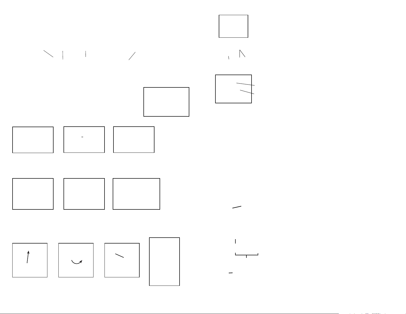
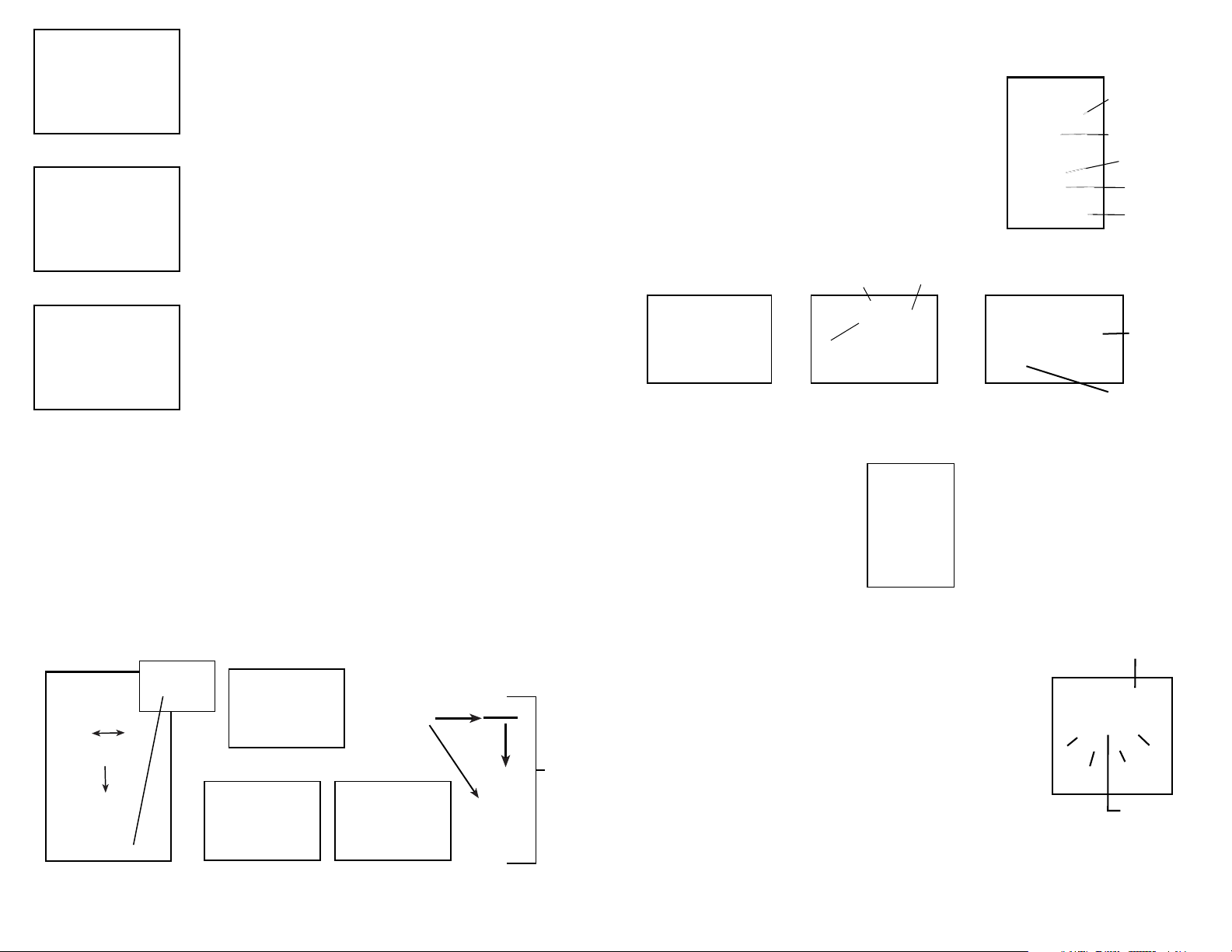
INSTALLING THE PUMP HANDLE
The pump handle can be mounted on either side of the pump shaft (A).
T
o install the pump handle place the handle (C) over the shaft (A)
aligning the pump handle hole and shaft hole. Push the straight side of
the cotter pin (B) through the aligned hole as shown in figure 1 thru 3.
There are holes in the pump handle to allow for either left (fig.4) or right
(fig.5) hand mounting.
Figure 1
Cotter Pin
Figure 4
Left Hand
Figure 2
Line up holes
Figure 5
Right Hand
Figure 3
Slide pin through holes.
Pump Handle
Positioned For Use
(right hand shown)
Pressure
cylinder base
A
B
C
Figure 6
Piston Cylinder
Notch
DÉMONTER ET RÉPARER LE ROBINET D’ARRÊT
1) Robinet d’arrêt assemblé (figure 1).
Figure 1
2) Retirez la cheville de retenue (A) (figure 2), placez
l'extrémité à encoche de la cheville sur une surface dure et
poussez vers le bas. Retirez la cheville de retenue et glissez
A
Figure 2
pour sortir la poignée de la soupape.
STOW- AWAY PUMP HANDLE
Pull
up
Rotate
180º
3E
Set
into
slot
Figure 3
Tige de la
soupape
C
3) Retirez l'écrou de blocage (joint torique attaché), le ressort et la
tige de la soupape (B) (figure 3). Remplacez les pièces usées.
Lubrifiez les joints toriques et remontez en inversant les Ètapes
precedentes. Placez la rainure de la poignee dans l'endroit à fentes
de la tige de la soupape et assurez-vous que la pince de verrouillage
B
soit bien placee (voir la section « Information utile sur la
pulvérisation »). Insérez la cheville de retenue. Enfoncez la poignée
et dégagez-la quelques fois pour répartir la graisse uniformément.
Vérifiez le filtre (C) au bout du robinet d'arrêt pour tout signe de
débris. Retirez le filtre et rincez à l'eau pour le nettoyer.
10F
SPRAYER COMPONENTS & USE INFORMATION, Continued
7) Appliquez un peu de pétrolatum à l'intérieur de la paroi du
cylindre du piston et sur le collier, et réinstallez l'assemblage du
piston dans le cylindre du piston.
Figure 7
8) Insérez le piston incliné par rapport au bord d'entrée du
collier placé sur la fente du cylindre du piston. Boulonnez
l'assemblage du piston à l'arbre de la pompe en utilisant les
boulons du levier.
Figure 8
9) Replacez le bouchon protecteur. Resserrez l'écrou et le
boulon. Réinstallez la poignée de la pompe. Replacez le
boyau et fixez fermement la pince du boyau en place.
Figure 9
DÉMONTER ET RÉPARER L'ASSEMBLAGE DE LA POMPE
DÉMONTER ET RÉPARER L'ASSEMBLAGE DE LA POMPE
Ne retirez le cylindre de compression que si le filtre à cartouche est bloqué ou si le pulvérisateur
fuit à l'endroit où le cylindre de pression et la cuve se joignent.
1. Dégagez la pression du pulvérisateur et retirez tout le liquide de la chambre de pression et de la cuve.
2. Retirez le boyau.
3. Retirez le filtre dans le réservoir du cylindre de pression (qui se trouve à l'intérieur du réservoir - fig.1).
4. Retirez les 2 boulons rattachant le levier du pivot à l'arbre de la pompe et retirez l'assemblage du piston
(fig. 2a et 2b).
5. Retirez la large pince retenant la chambre de pression et la cuve ensemble (fig. 1).
6. Faites basculer la chambre de pression d'avant à arrière et enfoncez pour le libérer de la cuve (fig. 1).
7. Après l'avoir libéré, tout l'assemblage de la pompe peut Ítre retiré en le faisant passer à travers
l'armature de base (fig. 3a et 3b).
Pince
Joint torique
de la
chambre de
pression
Figure 2a
Assemblage de
pompe
B
INSTALLING THE SHOULDER STRAP
The backpack strap is provided with multiple features including
shoulder strap, chest strap, waist belt, lumbar support and back pad
(figure 1). The top of both the shoulder straps and back pad straps
are attached to the top of the tank and are removable. The back pad
strap attaches to the bottom of the tank (figure 2). The back pad is
attached to its strap with velcro and is removable ( figure3). The
strap from the lumbar support attaches to the base tube on the
bottom of the tank (figure 4).
Back Pad
p
Stra
Velcro
Attachment
Figure 2
Back Pad strap attachment
WAND CLIP
The wand can be attached to the pump
handle using the wand clip.
PRESSURE REGULATOR
The spray tank and the pressure chamber are separate compartments in
the spraye
within the unit and is built to withstand normal operating pressure. The
backpack sprayer has a built-in, adjustable regulator to control spray
pressure. If required adjust the regulator before filling the sprayer tank. To
adjust, first remove the tank cap and filter basket. Look into the tank to
view the top of the regulator. There are four “fingers” on the regulator’s
knob. The fingers are numbered 1, 2, 3, and 4. Finger 1=30 psi, Finger
2=45 psi, Finger 3=60 psi, and Finger 4=80 psi. The higher you set the
pressure, the more liquid will exit the sprayer in a given amount of time.
Note: the higher the pressure is set, the smaller the droplets. Therefore,
there will be more “drift” in the expelled liquid at higher pressures. To
adjust, push down the regulator knob and rotate to align with the
alignment pin to the desired number.
r. Pressure is maintained in a separate pressure chamber
Figure 3
Removable Back Pad
Removable
Back Pad
Figure 4
Strap
Figure 1
Strap
Attachment
Assembly
30psi
45psi
Shoulder
Strap
Back
Pad
Chest Strap
Lumbar
Support
Waist
Belt
Lumbar
Support
Base Tube
Pressure
Chamber
60psi
Pressure
Regula
80psi
tor
Figure 1
Figure 2b
9F
Figure 3a Figure 3b
4E
SPRAYER COMPONENTS & USE INFORMATION, Continued
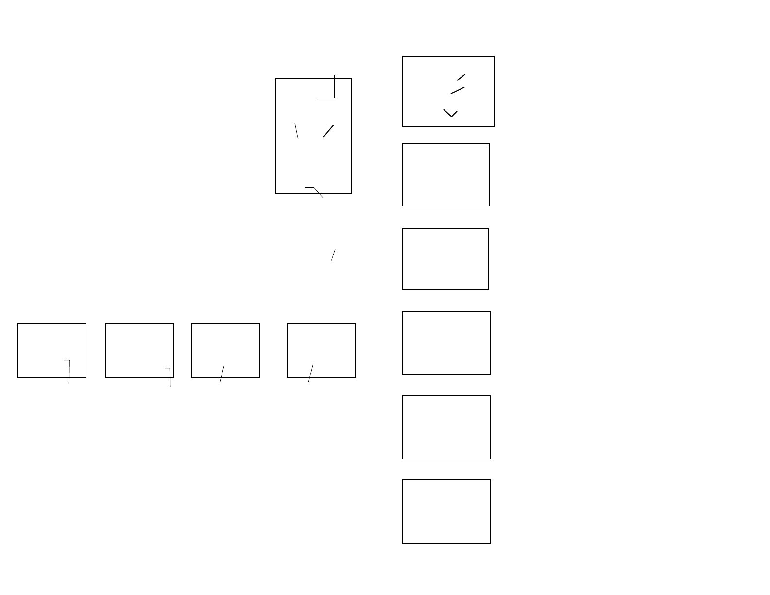
DÉMONTER ET RÉPARER LA POMPE À PISTON
4 STAGE FILTERING SYSTEM
This backpack sprayer is equipped with a 4 stage filtering system (see figure 1).
Stage 1 is a filter basket incorporated into the tank opening where fluid is
added. Stage 2 and 3 filters are located at the inlet of the pressure cylinder.
Stage 2 is a removable In-Tank filter. Stage 3 is a removable filter cartridge
integrated into the pressure cylinder. Stage 4 is a removable filter incorporated
into the shut-off assembly. Periodic cleaning of these filters is recommended to
insure consistent fluid flow through the sprayer. This will also reduce sprayer
component wear.
Stage 3 filter cartridge cleaning requires removal of the entire pressure cylinder
assembly (see section “disassembling and repairing the pressure cylinder”).
Once the pressure cylinder is removed the stage 3 filter can be removed for
cleaning (see figure 3). Periodic cleaning of the stage 2 filter is highly
recommended and will reduce the need to perform this disassembly. It is best
to have no or minimal fluid in the tank before removing and reinstalling the
stage 2 In-Tank filter. The In-Tank filter needs to be oriented in a specific way
when inserted into the pressure cylinder base (see figure 2).
The stage 4 filter is a removable filter incorporated into the inlet side of the
shut-off valve (see section “disassembling and repairing the shut-off valve”) .
Make sure pressure is released before detaching the hose from the shut-off. It
is best to have no or minimal fluid in the pressure cylinder before removing
and reinstalling the stage 4 shut-off filter as fluid can leak from the hose.
Figure 2 Stage 2 (removable In-Tank filter)
Figure 3 Stage 3 (removable filter cartridge)
Figure 1
Stage 2
(removable
ank filter)
In-T
Stage 1
(filter
basket)
Pressure
Cylinder
Stage 3 (removable
filter cartridge)
Stage 4
(Removable
Shut-off filter)
A
Figure 1
Figure 2
Figure 3
1) Retirez la goupille fendue et la poignée de la pompe. Placez la pompe vers
C
B
vous et déposez l'appareil sur le dos (figure 1). Desserrez la pince du boyau et
retirez le boyau du pulvérisateur. Attention : il pourrait rester du liquide dans le
boyau et dans le cylindre de pression. Retirez l'écrou et le boulon du bouchon
protecteur et retirez le bouchon (réf. figure 9). Tournez l'arbre de la pompe pour
atteindre les deux boulons du levier (A). Utilisez une clé allen et retirez les
boulons du levier. Sortez l'assemblage de piston (B) du cylindre du piston (C).
2) Retirez l’assemblage du cylindre de piston en tournant le cylindre dans le
sens antihoraire en regardant le pulvérisateur du bas. Attention : le cylindre
du piston pourrait avoir des bords tranchants.
3) Vérifiez s'il y a des égratignures verticales à l'intérieur du cylindre du
piston et dans le piston. Si l'un ou l'autre ou les deux sont égratignés,
remplacez-les.
4) Pour remplacer le collier, retirez-le de la calotte du piston
avec le pouce (figure 6). Vous verrez des fentes ajustées pour
installer le nouveau collier sur la calotte du piston.
Guide edge facing away
from pressure c
ylinder
Guide edge on
ylinder
pressure c
pressure c
ylinder base
Filter cartridge removedFilter cartridge in
FILLING THE SPRAYER
Make sure the filter basket is in place to keep debris from entering the tank.
Determine the amount of mixture needed for your application. Add the proper amount of water to the
tank. Add the proper amount of chemical to the tank (check the chemical label for proper ratio of
chemical). Stir mixture in tank with a clean utensil (like a paint stirrer). The tank will hold the 4-gallon
(15.1L) capacity plus the chemical.
It is not necessary to completely fill the sprayer tank with each use. You can fill the tank with only the
amount needed for each application.
Always follow the manufacturer’s instructions included on their product label.
5E
Figure 4
5) Retirez la plaque porte-soupape et les joints toriques de l’extérieur du
cylindre du piston. Assurez-vous que les joints toriques sont réglés
correctement dans les rainures exposées, installez la nouvelle plaque portesoupape et les deux joints toriques. Il y a une deuxième plaque portesoupape à l’intérieur du cylindre du piston. Tirez la cheville rouge ou orange
et retirez la plaque porte-soupape utilisant un tournevis à tête Phillips n° 2.
Installez une nouvelle plaque porte-soupape et replacez la cheville de
retenue fermement en place avec un tournevis à tête Phillips n° 2.
Figure 5
6) Lubrifiez les deux joints toriques sur le cylindre du piston (ne laissez
aucune graisse sur la plaque porte-soupape) et vissez l'assemblage du
piston sur la base du cylindre de pression. Vissez le cylindre du piston dans
le sens horaire jusqu'à ce qu'il soit serré et que le joint torique inférieur ne
soit plus visible. Lorsqu'il est bien placé, la languette du cylindre du piston
s'alignera avec la rainure sur la base du cylindre de pression.
Figure 6
8F
 Loading...