

Page 1

Chaparral VFS113
Fibre Channel-to-SCSI Router
User’s Guide
Page 2

Page 3

Copyright
© 2000, 2001 Chaparral Network Storage, Inc.
Document Number: 07-0015-006-B
This document covers the VFS113.
All rights reserved. No part of this publication may be reproduced without the prior written consent of:
Chaparral Network Storage, Inc.
7420 E. Dry Creek Parkway
Longmont, Colorado 80503
http://www.chaparralnet.com
Trademarks
Chaparral Network Storage, Inc. and the Chaparral logo are trademarks of Chaparral Network Storage, Inc.
AHA and AIC are trademarks of Adaptec, Inc.
Windows is a registered trademark and Windows NT is a trademark of Microsoft Corporation in the U.S. and
other countries, used under license.
All other trademarks are owned by their respective owners.
Changes
The material in this document is subject to change without notice. While reasonable efforts have been made to
ensure the accuracy of this document, Chaparral Network Storage, Inc. assumes no liability resulting from
errors or omissions in this publication, or from the use of the information contained herein.
If you would like to provide comments or suggestions on the quality and/or accuracy of this manual, please
contact Chaparral at http://www.chaparralnet.com/manuals.
Chaparral reserves the right to make changes in the product design without reservation and without
notification to its users. Comments and suggestions can be sent to the address listed above.
Technical Support
If after reviewing this user’s guide, you still have questions about installing or using your Chaparral product,
please contact us at (303) 845-3200 or by e-mail at [email protected]
Federal Communications Commission Radio Frequency Interference Statement
WARNING: Changes or modifications to this unit not expressly approved by the party responsible for
compliance could void the user’s authority to operate the equipment.
This equipment has been tested and found to comply with the limits for a Class A digital device, pursuant to
Part 15 of the FCC rules. These limits are designed to provide reasonable protection against harmful
interference in a residential installation. This equipment generates uses, and can radiate radio frequency
energy, and if not installed and used in accordance with the instruction manual, may cause harmful
interference to radio communications. However, there is no guarantee that interference will not occur in a
particular installation. However, if this equipment does cause interference to radio or television equipment
reception, which can be determined by turning the equipment off and on, the user is encouraged to try to
correct the interference by one or more of the following measures:
I Reorient or relocate the receiving antenna.
I Increase the separation between equipment and receiver.
I Connect the equipment to an outlet on a circuit different from that to which the receiver is connected.
I Consult the dealer or an experienced radio/television technician for help.
I Use a shielded and properly grounded I/O cable and power cable to ensure compliance of this unit to the
specified limits of the rules.
This device complies with part 15 of the FCC rules. Operation is subject to the following two conditions: (1)
this device may not cause harmful interference and (2) this device must accept any interference received,
including interference that may cause undesired operation.
i
Page 4

Canadian Compliance Statement
This Class A digital apparatus meets all requirements of the Canadian Interference-Causing Equipment
Regulations.
Cet appareil numérique de la classe A respecte toutes les exigences du Règlement sur le matérial brouilleur du
Canada
EMC
Documents:
89/336/EEC—European Council Directive on the Approximation of the Laws of the Member states Relating
to Electromagnetic Compatibility (EMC Directive).
Test in g:
Emissions: EN 55022
Immunity: EN 50082-1
Emissions
Documents:
1 CISPR Publication 22/EN 55024—Limits and Methods of Measurement of Radio Interference
Characteristics of Information Technology Equipment (ITE).
2 Federal Communications Commission (FCC)
a) 47 Code of CFR, chapter I
i) Part 2—Frequency Alloc. And radio Treaty Matters; Gen. Rules and Reg.
(1) Subpart J - Eq. Auth. Procedures
ii) part 15—Radio Frequency Devices
(1) Subpart B - Unintentional Radiators
3 ANSI C63.4—Methods of Measurement of Radio-Noise Emissions from Low-Voltage Electrical and
Electronic Eq in the Range of 9 kHz to 40 GHz
4 ICES-003—Interference - Causing Eq Standard - Digital Apparatus
5 AS/NZS 3548—Limits and Methods of Measurement of Radio Disturbance Charac. of Info. Tech. Eq.
6 VCCI—Volunt. Control council for Interference by Info. Tech. Eq.
Test setup shall conform to ANSI C63.4
Testing to be performed to CISPR 22/EN55022 Class-A and FCC Class-A limits
The quasi-peak detection mode is to be used for measurements from 30 MHz to 1 GHz and the antenna should
be placed at a distance of 10 meters from the Equipment Under Test (EUT). To comply with the FCC Rules
and Regulations, testing must be performed to 5.3125 GHz (the 5th harmonic of the 1.0625 GHz clock) at a
test distance of 3 meters using the average detection mode.
Immunity
1 EN 50082-1: 1998—Electromagnetic Compatibility - Generic Immunity Standard - Part 1: Residential,
Commercial and Light Industry
2 EN 61000-4-2—Electromagnetic Compatibility (EMC) - Part 4: Testing and Measurement Techniques -
Section 2; Electrostatic Discharge Immunity Test
3 EN 61000-4-3—Electromagnetic Compatibility (EMC) - Part 4: Testing and Measurement Techniques -
Section 3: Radiated, Radio Frequency, Electromagnetic field Immunity Test
4 EN 61000-4-4—Electromagnetic Compatibility (EMC) - Part 4: Testing and Measurement Techniques -
Section 4: Electrical Fast Transient/Burst Immunity Test
5 EN 6100-4-5—Electromagnetic Compatibility (EMC) - Part 4: Testing and Measurement Techniques -
Section 5: surge Immunity Test
ii
Page 5

6 EN 61000-4-6—Electromagnetic Compatibility (EMC) - Part 4: Testing and Measurement Techniques -
Section 6; Immunity to Conducted Disturbances, Induced by Radio-Frequency Fields.
7 Not needed: EN 61000-4-8
8 EN 61000-4-11—Electromagnetic Compatibility (EMC) - Part 4: Testing and Measurement Techniques -
Section 11: Voltage Dips, Short Interruptions and Voltage Variations Immunity Test
Safety
We have tested to the current (latest) version of the documents, including all revisions.
Documents:
1 73/23 ECC—European Council Directive on the Harmonization of the Laws of the Member states Relating
to Electrical Equipment Designed for use Within Certain Voltage Limits (Low Voltage Directive).
2 UL 1950, 3rd Edition—Safety of Information Technology Equipment (ITE), including Electrical Business
Equipment
3 CAN/CSA C22.2 #950-95—Safety of Information Technology Equipment (ITE), including Electrical
Business Equipment
4 EN 60950—Specification for Safety of Information Technology Equipment (ITE), including Electrical
Business Equipment
5 IEC 950—Safety of Information Technology Equipment (ITE), including Electrical Business Equipment
The VFS113 has been tested to EN 6100-3-2, EN 6100-3-3, and EN 55024.
Laser Safety
Certification and Classification Information
This product uses Gigabit Interface Converters (GBIC) to interface with Fibre Channel links. Optical GBICs
used with this product contain internal lasers. In the USA, all optical GBICs certified as Class 1 laser products
and conform to the requirements contained in the Department of Health and Human Services (DHHS)
regulation 21 CFR Subchapter J.
Outside the USA, all GBICs are certified as Class 1 laser components that conform to the requirements
contained in the International Electrotechnical Commission (IEC) standard 825 (1994) and Amendment 1
(1990) along with CENELEC (European Committee for Electrotechnical Standardization) European
Normalization standard EN 60825 (1992).
The user is required to ensure that the optical GBIC being used meets all of the above requirements.
Required certifications include one or more of the following:
I Recognized Component by Underwriters Laboratories
I Certified by the Canadian Standard Association
I Certified by VDE (Germany) and/or Certified by Statens Provningsanstalt (SP) in Sweden
iii
Page 6

iv
Page 7

1 Introduction
About This Guide ..............................................................................................1-1
Conventions ................................................................................................1-2
Chaparral VFS113 Router Benefits and Features .............................................1-2
About Serverless Backup ............................................................................1-3
Specifications ....................................................................................................1-4
2 Installing the Router
Unpacking the Router ........................................................................................2-1
Installing the Router ..........................................................................................2-2
Installing on a Desktop ...............................................................................2-2
Installing in a Rack .....................................................................................2-3
Installation Configuration Examples ..........................................................2-4
Connecting the Router .......................................................................................2-7
Connecting to the SCSI Channels ...............................................................2-7
Connecting to the Fibre Channel Port .........................................................2-8
Connecting to the RS-232 Port ................................................................... 2-9
Connecting to the Ethernet Port ................................................................2-10
Powering Up All Devices ................................................................................2-10
Understanding the LED Status Lights ........................................................... 2-11
Router Default Settings ...................................................................................2-12
Contents
3 Configuring the Router
Accessing the Router Administrator Software ..................................................3-1
Accessing the Router Administrator Using the RS-232 Serial Port ...........3-1
Accessing the Router Administrator Using the Ethernet Port ....................3-3
Using the Ethernet Port for the First Time ...................................................... 3-3
Accessing the Router Software Using the Ethernet Port ................................. 3-4
Accessing the Network Management System .............................................. 3-5
Navigating the Router Administrator Software ..........................................3-5
Changing the Screen Display ......................................................................3-6
Changing Router Configuration ........................................................................ 3-6
Selecting the Topology ...............................................................................3-7
Changing the Router’s Loop ID ..................................................................3-8
Changing the Router’s FC LUN ...............................................................3-10
Changing the SCSI ID Assigned to Each Router Channel ....................... 3-12
v
Page 8

VFS113 Rack/Desktop Model User’s Guide
Disabling the Termination on an HVD Router .........................................3-13
Setting the Date and Time ........................................................................3-14
Changing the Scan Delay ..........................................................................3-15
Enabling and Disabling the Alarm ............................................................3-16
Restoring the Default Settings .................................................................. 3-18
Rebooting the Router .......................................................................................3-19
Changing and Displaying Device Information ................................................3-20
Changing the Mapping Mode (AUTO or FIXED) ...................................3-20
Changing Device Addresses (FC LUNs) ..................................................3-21
Displaying the Devices Connected to the Router .....................................3-23
Displaying the FC-to-SCSI Address Map ................................................3-23
Displaying Router Information .......................................................................3-24
Displaying the Event Log .........................................................................3-24
Displaying Hardware and Configuration Information ..............................3-27
Displaying the Router’s FC LUN .............................................................3-30
Upgrading Firmware .......................................................................................3-31
Upgrading the Router’s Firmware ............................................................3-31
Upgrading the Ethernet Card’s Firmware .................................................3-33
4 Troubleshooting
Chaparral Technical Support .............................................................................4-1
Problems During Bootup ................................................................................... 4-1
Restoring the Default Configuration Through the Flash Utility .................4-3
Terminal Emulator and COM Port Problems ....................................................4-4
Device SCSI Channel Problems ........................................................................4-5
Router is Not Responding .................................................................................4-6
Using the Loader Diagnostics Menu .................................................................4-6
Using the Loader Utility Menu .........................................................................4-6
Event Logs .........................................................................................................4-6
Event Log File Capture .....................................................................................4-7
Voltage and Temperature Errors and Warnings ................................................4-8
Setting Up Debug Logging ................................................................................4-8
A Address and Device Mapping
Loop ID to AL_PA Mapping ........................................................................... A-3
vi
Page 9

Contents
B LAN Configuration
Configuring the Router for TCP/IP .................................................................. B-1
Using Address Resolution Protocol ........................................................... B-2
Dynamic Host Configuration Protocol Configuration ............................... B-3
Configuring the Additional LAN Settings ....................................................... B-3
System Configuration Screen .................................................................... B-4
TCP/IP Configuration Screen ....................................................................B-5
SNMP Configuration Screen ..................................................................... B-6
Restarting the LAN Board ......................................................................... B-7
System Information screen ........................................................................ B-7
Returning to the Router Administrator Software .......................................B-7
C Reference Documents
Standards ..........................................................................................................C-1
Books ................................................................................................................ C-2
Glossary
Index
vii
Page 10

VFS113 Rack/Desktop Model User’s Guide
viii
Page 11

1
Introduction
This User’s Guide explains how to install and use the Chaparral™ VFS113 router. This
member of the Velocity family of routers is a Fibre Channel (FC)-to-Small Computer
System Interface (SCSI) router that enables connectivity between SCSI devices and
storage area networks (SANs). The router provides Fibre Channel connection to SCSI
devices allowing them to be attached to either a Fibre Channel Arbitrated Loop (FC-AL)
or switched fabric.
The router allows SCSI and Fibre Channel devices to communicate seamlessly by
converting data to the appropriate protocol and routing it to the desired destination.
The router supports a variety of SCSI devices including:
I Hard disk drives
I Tape drives
I Tape libraries
I Optical devices and libraries
I RAID controllers
About This Guide
This User’s Guide describes how to install and configure your book title. It assumes that
you are familiar with the basic functions of your computer system. It also assumes that
you are familiar with Fibre Channel configurations and basic network administration
terminology.
1-1
Page 12

VFS113 Rack/Desktop Model User’s Guide
Conventions
This Guide uses several typographical conventions to help explain how to use the router.
Convention Convention
Bold Wor ds in bold indicate items to select such as menu items or
command buttons.
Ctrl-r Keys you press simultaneously. In this example, hold down the
Ctrl key and press the r key.
Notes give you important information that may affect how you
decide to set up your system.
Cautions warn you about actions that may permanently delete
!
data or cause damage to your system.
Tips give you information that can help you improve the
performance of your system.
Chaparral VFS113 Router Benefits and Features
The router offers you three key benefits:
I Allows you to connect legacy SCSI devices to Fibre Channel SANs
I Allows you to manage these devices
I Frees your servers from storage-related traffic, such as your data backup load, using
the Extended Copy option.
The router provides the following product features:
I One full-duplex, 1.0625 Gbit/sec Fibre Channel host port
I FC-AL and Fibre Channel Switched Fabric (FC-SW) topologies
I Class 3 service
I Private Loop Direct Attach (PLDA) compliant
I SCSI-FCP (SCSI over Fibre Channel)
I Support for up to 128 FC initiators with up to 32 concurrently active
I Three independent SCSI device channels
I Support of up to 45 SCSI IDs on three independent SCSI channels
(15 IDs per channel)
1-2
I Addressing of up to 64 LUNs
I One RS-232 serial port
I One 10BaseT Ethernet port
Page 13
Introduction
I Industry-leading data transfer (MB/sec) and transaction processing rates (IOPS)
I Automatic SCSI device discovery and SCSI-to-FC address mapping
I Retention of SCSI-to-FC addressing during device removal/addition and between
power cycles
I Support for Persistent Reserve In and Persistent Reserve Out commands
I Support for Report LUNs command
I Firmware upgrades via RS-232
I Warnings and automatic shutdown for out-of-specification temperature and voltages
I Embedded Configuration Application Programming Interface (CAPI) for
management and Graphical User Interface (GUI) development
I Extended Copy command available for serverless backup
The router is available in both low-voltage differential/single-ended (LVD/SE) and highvoltage differential (HVD) SCSI models.
Note: It is important to know which model you have and the associated
features. (See Specifications below.)
About Serverless Backup
Recent advances in data protection architectures have added the ability to back up data by
moving it directly from disk to tape without first passing through a backup server. This is
called serverless backup, and it utilizes a new SCSI command, Extended Copy (EC). A
host is involved in executing the EC command, though it is typically not the server. The
Chaparral family of Intelligent Storage Routers is enabled to execute the EC command
under the control of most major backup applications.
The EC command consists of three primary pieces of information:
I Source addresses
I Destination address
I In-line data
The source addresses tell the router where the data that is being copied is physically
stored, on what device and at what physical locations. This information is provided by a
backup application, which must translate file information into the physical storage
locations. The application sends this list of addresses in the order it is to be written to the
destination device, often a tape drive in a backup scenario.
For the destination address, the EC command assumes that any tape device that is being
copied to is in the proper location, so all the router needs to know is its target address,
typically a LUN on the SAN. The in-line data is used to allow applications to maintain a
specific format, and can be used to write any data the application may require for
restoration.
1-3
Page 14

VFS113 Rack/Desktop Model User’s Guide
The EC command, as implemented in the Chaparral router, requires no administration.
Administering an EC environment is most intensive on the application side. Chaparral
supports the Storage Networking Industry Association Extended Copy Specification
(ANSI T10/ 99-143R1). Any questions related to using a Chaparral router in an EC
environment should be directed to the application provider or your reseller. If you are
developing EC enabled applications, contact Chaparral for information on our specific
implementation.
Specifications
The book title is a self-contained FC-to-SCSI router in a 1U enclosure with an integrated
power supply. The router is ideal for attaching legacy SCSI storage devices to Fibre
Channel SANs. You can install the unit in an industry-standard 19
Chaparral-supplied mounting brackets. The router can be installed in either frontmounting or rear-mounting configurations. Table 1-1 provides additional product
specifications.
Table 1-1. Product specifications
" cabinet using the
Item Specification
Physical 1U enclosure (1.75" H x 17" W x 10.5" D)
Rack mount (with detachable brackets) or desktop use
Front- or rear-mount in racks
Weight: approximately 8 lbs
Fibre Channel GBIC housing for either optical or copper cabling
Supports data transfer up to 100 MB/sec
(Devices connected via this port are referred to as front-end
devices.)
SCSI LVD/SE model
I Supports Ultra2 wide data transfer up to 80 MB/sec per
channel
I Has internal SCSI termination
HVD model
I Supports Ultra wide data transfer up to 40 MB/sec per channel
I Has internal SCSI termination
(Devices connected to the SCSI channels are referred to as backend devices.)
Connections Fibre Channel (GBIC)
Three SCSI Channels (68-pin)
RS-232 serial port (RJ-12)
10BaseT Ethernet Port (RJ-45)
AC Power
1-4
Page 15

Introduction
Table 1-1. Product specifications (Continued)
Item Specification
Indicators Fibre Channel activity
SCSI activity (3)
Status
Fault
Switches AC Power On/Off
RS-232/Ethernet configuration port
Environmental +0°C to +40°C ambient, normal operating (an alarm sounds
when router operates between +0°C to +5°C and +35°C to
+60°C)
-40°C to +60°C ambient, nonoperating
10% to 85% normal operating, noncondensing
5% to 90% nonoperating, noncondensing
85 to 264 VAC, 47 to 63 Hz, autoranging power supply
❒
!
Caution: The LVD interfaces require LVD-qualified SCSI cables.
1-5
Page 16

VFS113 Rack/Desktop Model User’s Guide
1-6
Page 17

2
Installing the Router
This chapter provides step-by-step instructions for installing the router.
You must take many factors into consideration while planning the router installation. Due
to the versatility of the router and the diversity of available host platforms, host bus
adapters (HBAs), switches, hubs, storage devices, and applications, only general
guidelines are found in this Guide. For examples of the most common configurations, see
Installation Configuration Examples on page 2-4.
You can mount the router in a standard 19" rack or place it on a table or desktop. Be sure
the operating environment meets the requirements found in Specifications on page 1-4.
To install the router, you need to complete the following tasks in sequence:
1 Unpack the router. See page 2-1.
2 Install the router. See page 2-2
3 Connect the router. See page 2-7.
4 Power up all devices. See page 2-10.
Unpacking the Router
Carefully unpack the router and ensure that you have all the parts specified below:
I Router
I Five rubber feet
I Power cable
I RS-232 cable
I User’s Guide
I Mounting brackets (with 4 Phillips screws that are already screwed into the side of the
router)
To unpack the router:
1 Place the shipping container on a flat, clean, stable surface.
2 Carefully remove the router and verify the contents against the packing list.
3 Remove the foam from the sides of the router and remove it from the plastic bag.
Save the original shipping container and packing materials in case future reshipment
is necessary.
2-1
Page 18
VFS113 Rack/Desktop Model User’s Guide
4 Visually inspect the router and notify your freight carrier immediately of any
damage.
5 Record the Media Access Control (MAC) address located on the label of the router
box for future reference.
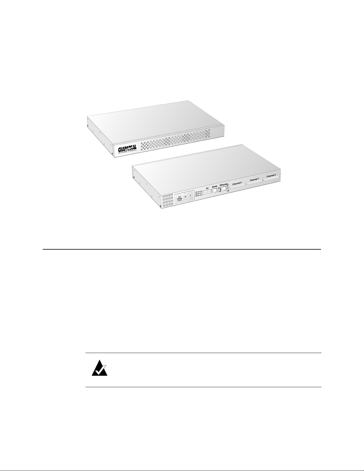
Figure 2-1 below shows the front and rear panels of the VFS113.
Figure 2-1. VFS113 front and rear panels
Installing the Router
You can install the router two ways:
I On a desktop or table
I In a standard 1U high, 19" rack
Installing on a Desktop
To install the VFS113 on a desktop:
1 Attach the five rubber feet to the recessed locations on the bottom of the router.
2 Place the router on a table, desktop, or other flat surface.
Note: Ensure that the front and rear panels have adequate clearance for
the fan, air intake vents (front), and access to all connections.
2-2
Page 19
Installing the Router
Installing in a Rack
You can install the router in a standard 1U high, 19" rack. You can either front or rear
mount the router.
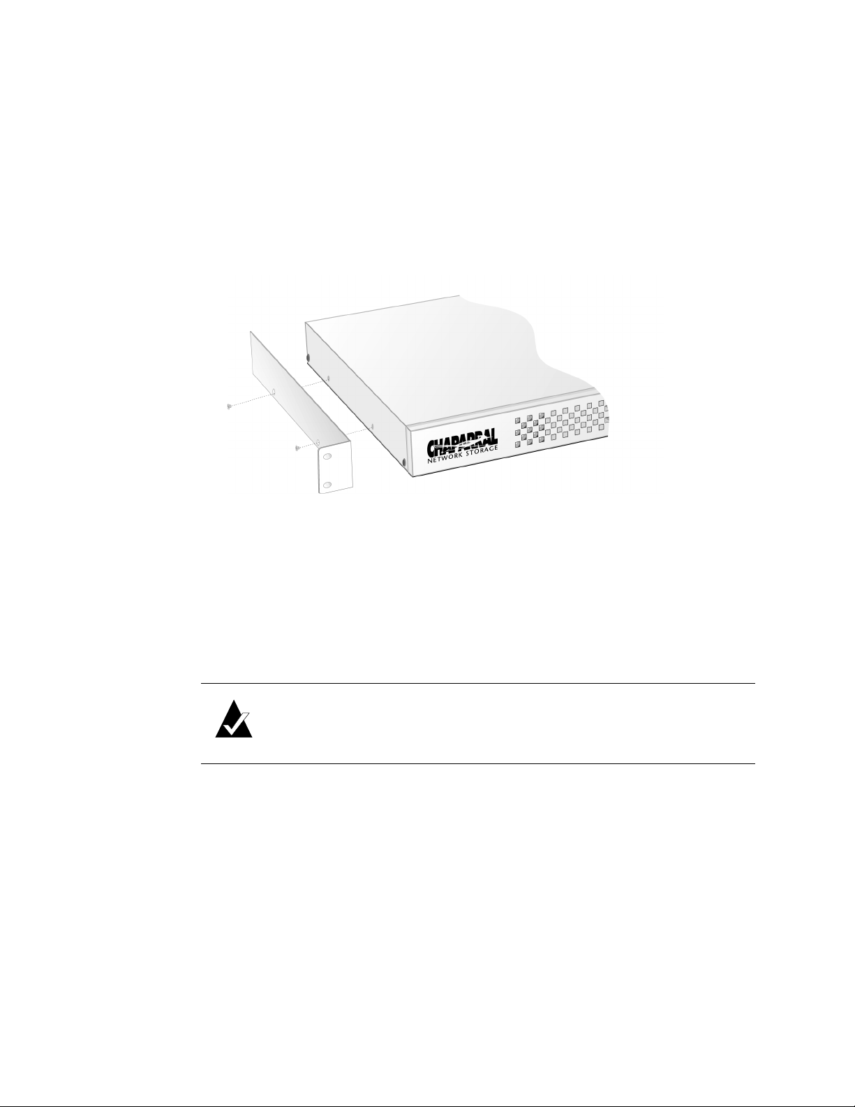
Parts required for this procedure (shown in Figure 2-2)
I Left and right mounting brackets (only left bracket shown)
I Four mounting screws (10-32 panheads)
Figure 2-2. Mounting bracket and screws
Recommended tools for this procedure:
I #2 Phillips screwdriver
To install the router in a rack:
1 Determine where in the rack you want to mount the router.
The mounting brackets are reversible, permitting either front or rear mounting.
Note: Ensure that the front and rear panels have adequate clearance for
the fan, air intake vents (front), and access to all connections. The proper
airflow is from the front of the router to the back.
2 Remove the screws from the sides of the router and keep the screws.
3 Using the screws you removed, attach the brackets to the router.
Be sure to place the front of the brackets at the front (for front mounting) or rear (for
rear mounting) of the router, depending on how you are mounting it in the rack.
You may have to squeeze the top and bottom of the router to align the holes.
4 Install in the 19" rack according to the rack’s instructions.
2-3
Page 20
VFS113 Rack/Desktop Model User’s Guide
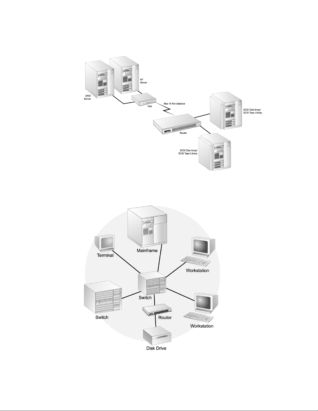
Installation Configuration Examples
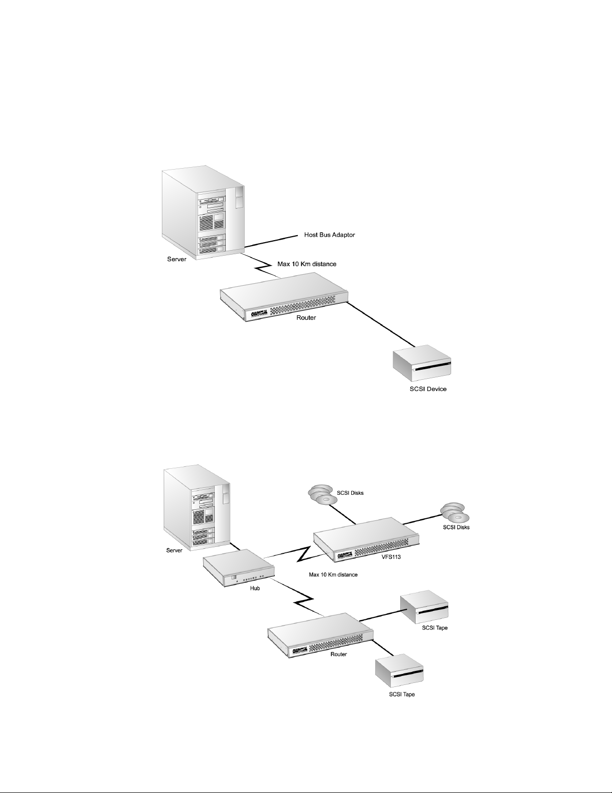
You can install the router in a variety of configurations to meet your needs. The examples
below show the most common installation configurations.
I Simple loop with two devices on a SAN (FC-AL)
Figure 2-3. Simple loop configuration example
I Single server on a SAN (FC-AL)
2-4
Figure 2-4. Single server configuration example
Page 21
Installing the Router
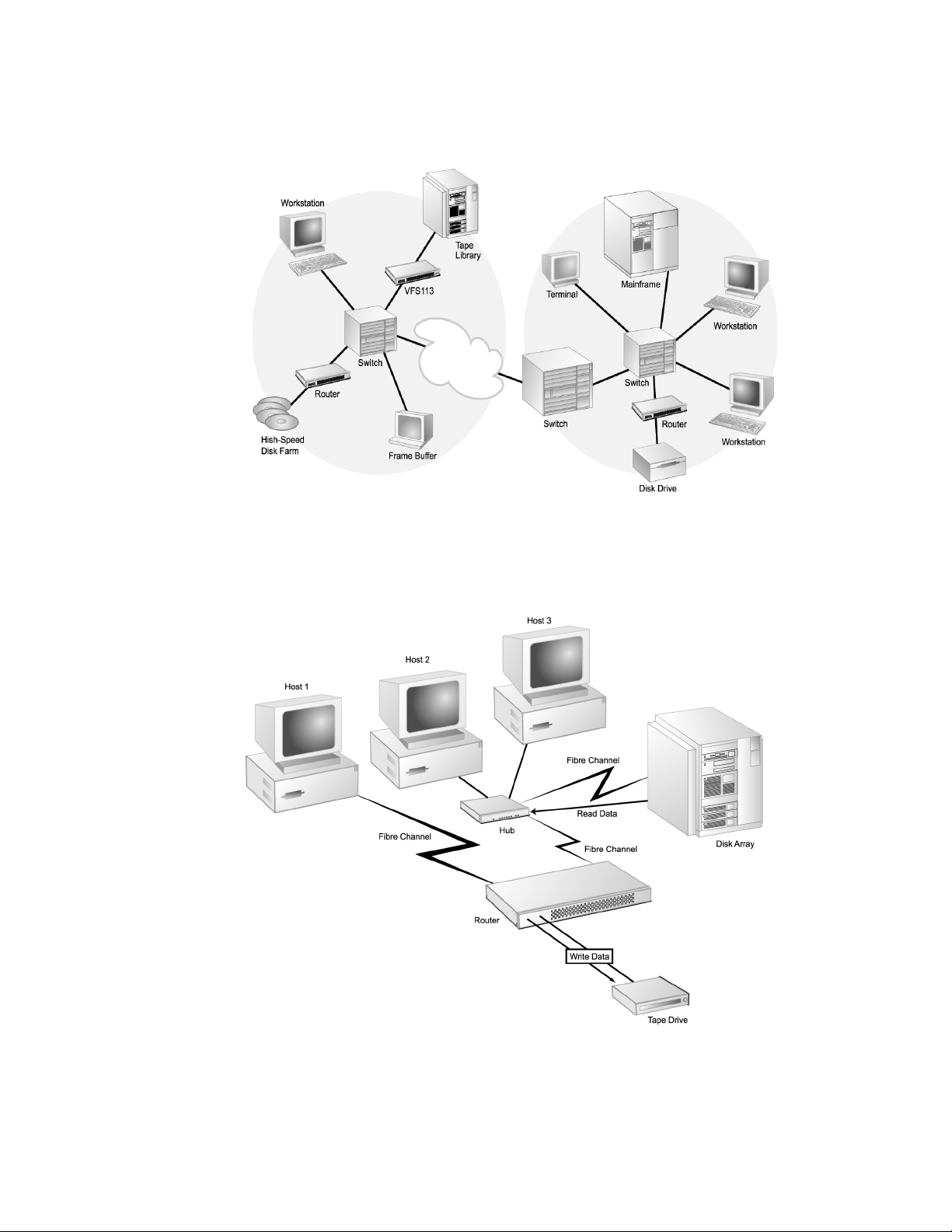
I Multiple servers on a SAN (FC-AL)
Figure 2-5. Multiple server configuration example
I SAN with fabric (FC-SW)
Figure 2-6. SAN configuration example
2-5
Page 22
VFS113 Rack/Desktop Model User’s Guide
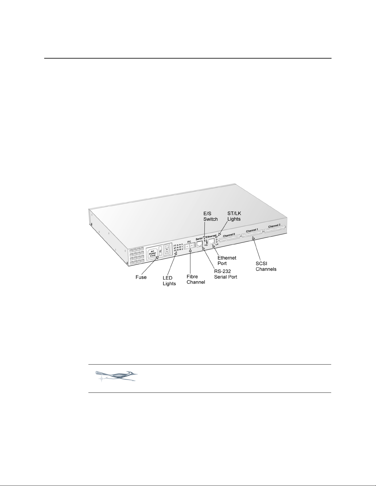
I Multiple SANs with fabric (FC-SW)
Figure 2-7. SAN with fabric configuration example
I Extended copy configuration—serverless backup that performs backup operations
directly from disk to tape without copying the data to the server
2-6
Figure 2-8. Extended copy configuration example
Page 23
Installing the Router
Connecting the Router
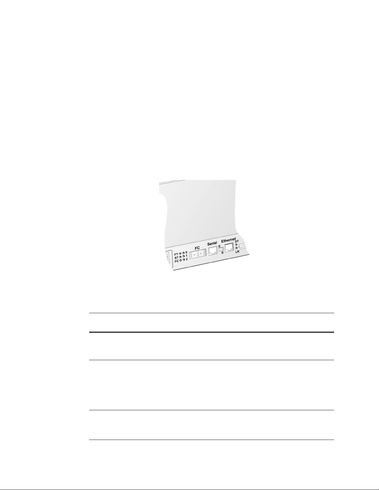
The router has several types of data connections:
I Fibre Channel (gigabaud interface connector [GBIC])—permitting connection to
other FC devices, typically through an arbitrated loop or SAN with fabric.
I Three SCSI channels—permitting the connection of up to 15 devices on each channel.
I RS-232 serial port—for configuration and management of the router.
I Ethernet (10BaseT)—connects to your local area network (LAN) to permit
configuration and management of the router.
For first time installation, install the SCSI devices first to ensure the router and its
assigned devices are working properly. You should connect all SCSI devices to the router
and power it on. After proper operation is established, you can proceed to connect the FC
host and the RS-232 or Ethernet ports.
Figure 2-9. Rear panel components
Connecting to the SCSI Channels
With the VFS113, you can attach SCSI storage devices to one, two, or three of the router’s
SCSI channels. Up to 15 SCSI devices can be attached to each channel (45 total). You can
attach SCSI storage devices to channel 0, for a maximum of 15 SCSI devices.
Tip: For optimal performance, use channels 1 and 2 first, then
channel 0 on the VFS113.
2-7
Page 24

VFS113 Rack/Desktop Model User’s Guide
You must use the proper SCSI cables on the model you purchased. For example, if you
purchased the LVD model, you must use LVD-qualified SCSI cables. Symbols on the rear
panel tell you which model you have.
LVD/SE
SCSI DIFF
SCSI
68-pin SCSI (LVD/SE model)
Ultra wide, 68-pin SCSI (HVD model)
To connect devices to the SCSI channels:
1 The router must be turned off.
2 Turn off the SCSI devices you want to connect.
3 Connect one end of a SCSI cable to a SCSI channels on the back of the router.
LVD/SE (wide, Ultra-2 SCSI),
See Figure 2-9 on page 2-7.
4 Connect the other end of the SCSI cable to the SCSI device.
Make sure each device on the SCSI bus has a unique address (the VFS113 uses
address 7 by default).
5 Make sure that each channel is properly terminated.
Termination on the LVD/SE model is always enabled at the router. You must also
terminate the SCSI bus at the device end.
Termination on the HVD model can be disabled for operation in the middle of the bus.
Connecting to the Fibre Channel Port
You can connect the router directly to an FC HBA or to an FC switch or hub. You must use
proper FC components (for example, GBICs, media interface adapters [MIAs], and FC
cable, either optical or copper). Contact Chaparral for information on components tested by
Chaparral and advice on attaching SCSI devices in an optimal manner for your applications.
You will need to purchase a GBIC through your distributor. The GBIC connector is
available in four different versions:
I Copper (Active)
–DB-9
– HSSDC
I Optical
–Short wave
– Long wave
2-8
Page 25

Installing the Router
To connect to the Fibre Channel port:
1 Be sure the router is turned off.
2 Insert the GBIC into the Fibre Channel port.
See Figure 2-9 on page 2-7. The GBIC is keyed and can only go in one way.
Be sure that the GBIC locks into place.
3 Connect one end of the Fibre Channel cable to the GBIC.
4 Connect the other end of the Fibre Channel cable to a server’s HBA or to an
arbitrated loop hub or fabric switch.
Connecting to the RS-232 Port
You use the RS-232 port to update the firmware, configure, and monitor the router using a
VT-100/ANSI computer with a terminal emulator. For more information about the
configuration and management capabilities, see Chapter 3, Configuring the Router.
You must use the RS-232 cable that came with the router or one configured like it. The
RS-232 cable is a standard 6-conductor flatline cable with an RJ-12 to DB-9 adapter. The
DB-9 pinout is as follows:
Table 2-10. DB-9 pinout
Pin Function
2Transmit
3 Receive
5Ground
The RJ-12 pinout is transparent.
Configure the RS-232 port in your terminal emulator software using the following
settings:
I Baud rate: 9600, 19200, 38400, 57600, or 115200; 115200 best for downloading
firmware upgrades
I Data Bits: 8
I Stop Bits: 1
I Parity: None
I Flow Control: None
To connect to the RS-232 port:
1 Be sure the router is turned off.
2 Using the RS-232 cable that came with the router, connect the RJ-12 end of the cable
into the RS-232 serial port on the router.
See Figure 2-9 on page 2-7.
2-9
Page 26

VFS113 Rack/Desktop Model User’s Guide
3 Move the E-S switch to the S position.
4 Connect the other end of the RS-232 cable (DB-9) to the COM port on the computer
that will monitor and configure the router.
Connecting to the Ethernet Port
You use the Ethernet (10BaseT) port to configure and manage the router. You use this
configuration option when you need to manage the router from a remote computer that is
connected to your LAN. For more information about the configuration and management
capabilities, see Accessing the Router Administrator Using the Ethernet Port on page 3-3.
To connect to the Ethernet port:
1 Be sure the router is turned off.
2 Connect one end of the Ethernet cable to the Ethernet port on the router.
3 Move the E-S switch to the E position.
See Figure 2-9 on page 2-7.
4 Connect the other end of the Ethernet cable to a network hub, router, or other
network connection.
Powering Up All Devices
After you have made all of the SCSI and RS-232 connections, you are ready to power up
the router and all devices connected to it. For best results, use a two-stage setup procedure.
First, connect all SCSI devices and the RS-232 port to ensure proper operation. Second,
connect the FC host port and finish installation.
To power up SCSI devices:
1 Be sure the router is turned off.
2 Attach the power cable to the back of the router.
See Figure 2-9 on page 2-7.
3 Plug the power cable into a power source.
4 Connect the SCSI devices to the router using the appropriate SCSI cables.
5 Power up the connected SCSI storage devices and allow them to come ready.
6 Power up the router and allow it to come ready.
The ST status light stays a steady yellow. See Understanding the LED Status Lights
on page 2-11.
2-10
!
Caution: Do not remove the router’s cover. The router has no userserviceable parts. Removing the cover will void the warranty.
Page 27
Installing the Router
The router recognizes all SCSI devices connected to the three SCSI channels on the
VFS113, and assigns each device a unique LUN address, which will be mapped as part of
a unique FC address. You can configure the router to assign itself a LUN for in-band
management, server-free backup, and other uses.
To make the host FC connection:
1 Connect the Fibre Channel cable to the router and the host computer, hub, or switch.
2 Power up connected servers, hubs, or switches on the network if necessary.
You are now ready to configure the router. To view the default settings, see Router Default
Settings on page 2-12. For information about changing the default settings, see Chapter 3,
Configuring the Router.
Understanding the LED Status Lights
LED status lights are on the rear panel of the router. For information about troubleshooting
problems indicated by the status lights, see Chapter 4, Troubleshooting.
Figure 2-11. LED status lights
Table 2-12 describes the meaning of the LED status lights located on the rear of the router.
Table 2-12. LED status lights
LED
Label Description Color Function
FT Router fault Red Solid on when router is powered-up
and fails any internal diagnostic or
detects a critical error
ST Router status Yellow Solid on when router is powered-up
and passes all internal diagnostics
Yellow Off when router either:
I Detects a warning/degraded mode
I Fails to boot
FC Host FC activity Green Solid on when FC link is connected
Solid off when FC link is
disconnected
2-11
Page 28

VFS113 Rack/Desktop Model User’s Guide
Table 2-12. LED status lights (Continued)
LED
Label Description Color Function
0 SCSI channel 0 activity Green Solid on when bus is active or busy
1 SCSI channel 1 activity Green Solid on when bus is active or busy
2 SCSI channel 2 activity Green Solid on when bus is active or busy
ST Ethernet Yellow Flashing or solid when 10BaseT link
is active or busy
LK Ethernet Yellow Solid when 10BaseT link is
connected
Router Default Settings
Table 2-13 below lists the router default settings. If these settings meet your needs, you
can use your router now. If they do not, you can change the settings. See Chapter 3,
Configuring the Router.
❒
Table 2-13. Router default settings
Setting Default For more information, see
Mapping Mode AUTO Changing the Mapping Mode (AUTO or
FIXED) on page 3-20
Topology LOOP Selecting the Topology on page 3-7
Router’s loop ID SOFT Changing the Router’s Loop ID on page 3-8
Router’s LUN SOFT Changing the Router’s FC LUN on page 3-10
Router’s initiator ID
(SCSI ID) on each
channel
Scan Delay 0 seconds Changing the Scan Delay on page 3-15
Alarm ENABLED Enabling and Disabling the Alarm on
7 Changing the SCSI ID Assigned to Each
Router Channel on page 3-12
page 3-16
2-12
Page 29

3
Configuring the Router
You can display and change a variety of settings using the Router Administrator software.
Using the Router Administrator, you can:
I Change the router configuration settings (see page 3-6)
I Reboot the router (see page 3-19)
I Display information about the router (see page 3-24)
I Display information about the devices attached to the router (see page 3-20)
I Change address mapping information for the devices (see page 3-20)
In addition, you can use the Flash Utility to update the router’s firmware. See page 3-31.
Accessing the Router Administrator Software
You can access the Router Administrator software using the RS-232 serial port or Ethernet
port connections on the router. You must connect a computer with terminal emulator
software, such as HyperTerminal, to the serial or Ethernet port and configure the port
according to either Connecting to the RS-232 Port on page 2-9 or Connecting to the
Ethernet Port on page 2-10.
Accessing the Router Administrator Using the RS-232 Serial Port
You can access the Router Administrator software using the RS-232 serial port.
To access the Router Administrator software using the RS-232 serial port:
1 From the computer connected to the router, start your terminal emulation software.
Be sure that your terminal emulation software is set to use the correct COM port on
your computer. See Terminal Emulator and COM Port Problems on page 4-4 for
more details on how the router can auto detect the baud rate.
3-1
Page 30
VFS113 Rack/Desktop Model User’s Guide
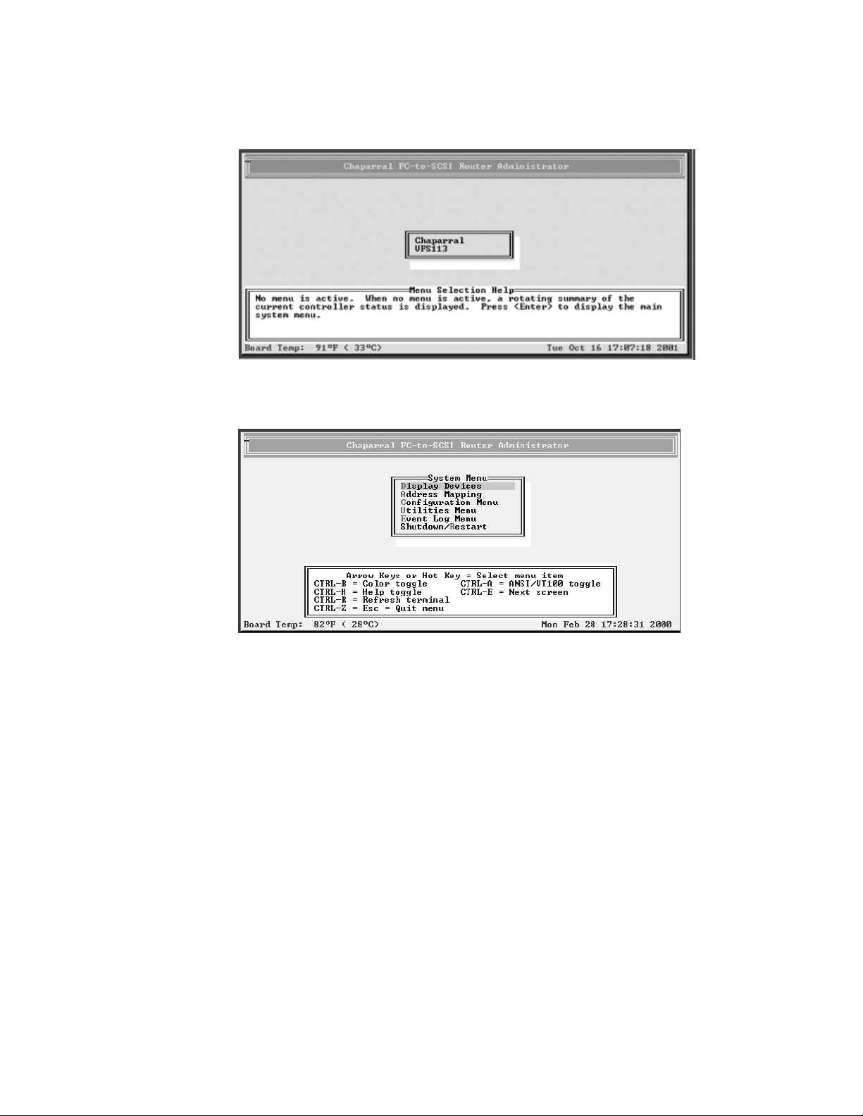
2 Press Ctrl-r.
The initial Chaparral FC-to-SCSI Router Administrator screen displays.
3 Press Enter.
The System Menu displays.
3-2
You can now perform all of the functions described in this chapter. All steps in this
chapter start from the System Menu.
If an alarm condition has occurred, you will see a message about the problem. This
message will also be stored in the event log.
Page 31
Configuring the Router
Accessing the Router Administrator Using the Ethernet Port
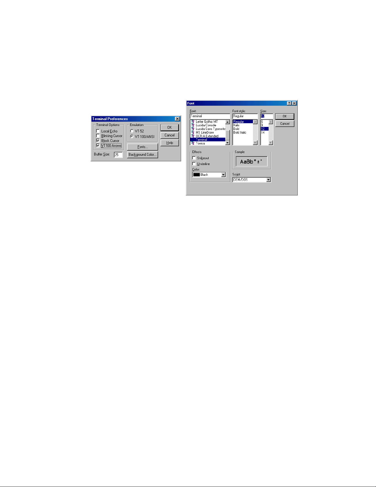
You can access the Router Administrator software using the Ethernet port using Telnet.
For Windows users, if you want to use Telnet, you must configure the preferences and font
from the Terminal menu each time as shown below.
Click Font to set
the font as shown
here.
Windows users may want to obtain HyperTerminal Private Edition from Hilgraeve, which
supports Telnet protocol and serial port protocol.
You can configure a variety of settings for the Ethernet connection. For more information,
see Configuring the Additional LAN Settings on page D-3.
Using the Ethernet Port for the First Time
Before you can access the Router Administrator software, you must set the IP address and
subnet mask for the controller. The default IP address is 204.132.192.216. You can do this
one of four ways:
I Setting up your computer with an IP address that is compatible with the controller
default of 204.132.192.216, such as 204.132.192.218.
I Using address resolution protocol (ARP) to set the address. See Using Address
Resolution Protocol on page D-2.
I Using Dynamic Host Configuration Protocol (DHCP) to set the address. See Dynamic
Host Configuration Protocol Configuration on page D-3.
Once you set the IP address and subnet mask, you can use the steps in the next section to
access the Router Administrator software.
3-3
Page 32
VFS113 Rack/Desktop Model User’s Guide
Accessing the Router Software Using the Ethernet Port
Note: If a Telnet session is active, you cannot make changes to the
configuration using the RS-232 connection.
You can configure a variety of settings for the Ethernet connection. For more information,
see Configuring the Additional LAN Settings on page D-3.
To access the Router Administrator software using the Ethernet port and the Telnet
utility:
1 Set up the IP address and subnet mask as described in Using the Ethernet Port for the
First Time on page 3-3.
2 At the DOS or UNIX prompt, enter telnet and press Enter.
3 Using the Terminal menu, select Preferences.
4 Select VT100 Arrows option, VT-100/ANSI emulation, and terminal font. Select
OK.
5 Enter the IP address or, using the Connect menu, select the controller IP address from
the menu (if present) and press Enter.
6 Enter the port number.
The port number is default port 23.
The Enter Password screen displays.
7 Enter your password and press Enter.
There is no default password, just press Enter.
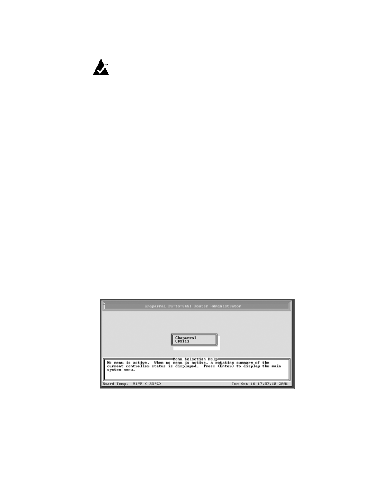
The initial Chaparral Router Administrator screen displays. If an alarm condition has
occurred, you will see a message about the problem. This message will also be stored
in the event log.
3-4
Page 33
Configuring the Router
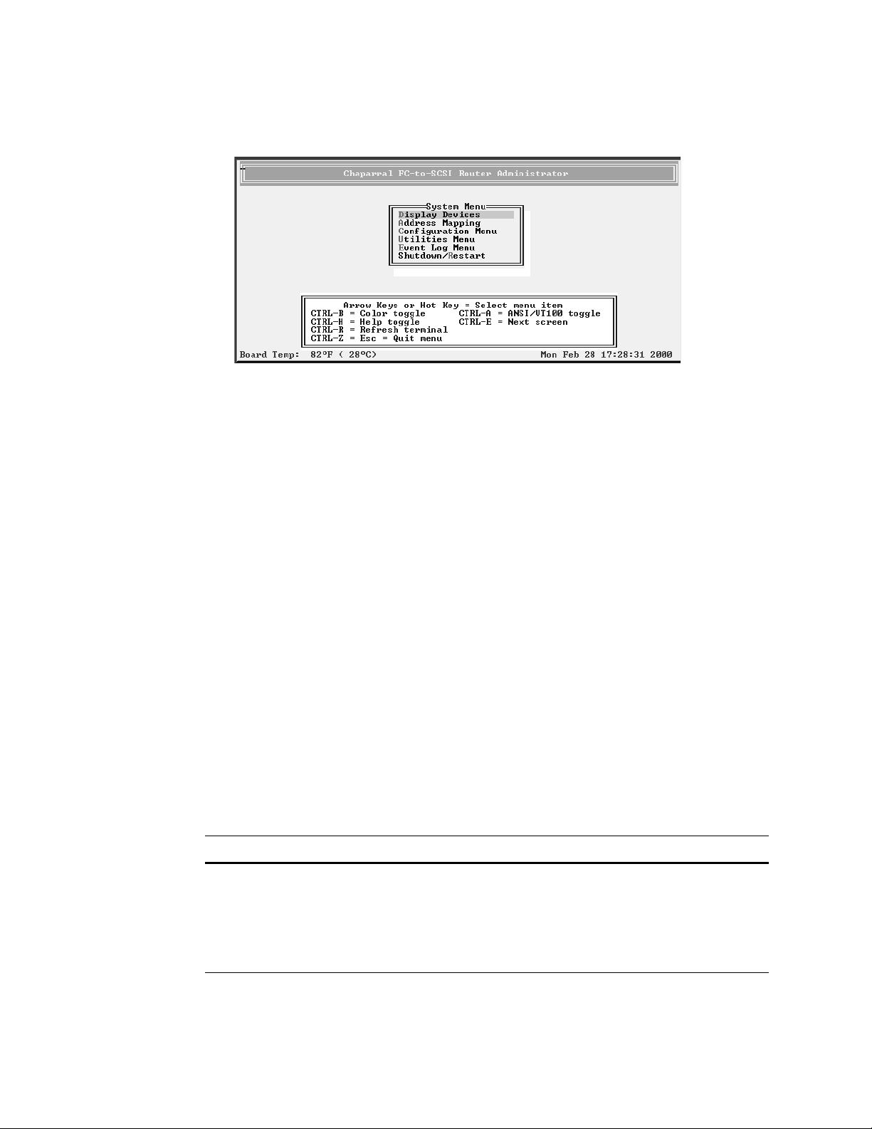
8 Press Enter.
The System Menu displays.
You can now perform all of the functions described in the following chapters. All
steps start from the System Menu.
Accessing the Network Management System
You can access the network management system software from the Router Administrator.
For more information about the settings available, see Configuring the Additional LAN
Settings on page D-3.
To access the network management system:
1 From the System Menu of the Router Administrator, select Configuration Menu
and press Enter.
2 Select LAN Configuration and press Enter.
The Enter Password screen displays. You can now access the network management
system screens and revise the settings as necessary.
Navigating the Router Administrator Software
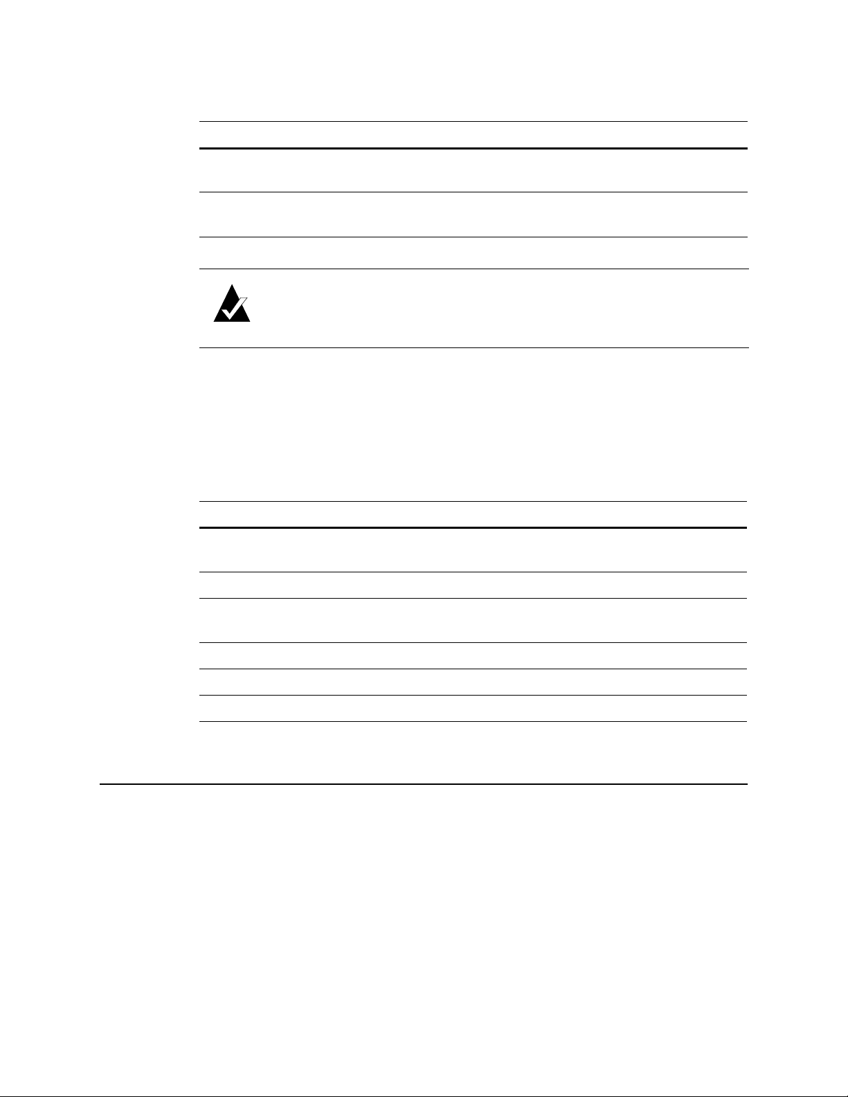
You can navigate the Router Administrator software using your keyboard. Table 3-1
below describes the primary navigation and selection methods:
Table 3-1. Router Administrator navigation
To Do this
Select a menu item Press the
or
Press the letter that is a different color (or
highlighted) in a menu item (hot key) and press
Enter.
↑ and ↓ and press Enter.
3-5
Page 34
VFS113 Rack/Desktop Model User’s Guide
Table 3-1. Router Administrator navigation (Continued)
To Do this
Return to the previous menu or
Press Esc or
←.
screen without saving your changes
Scroll through the available choices
Press the
↑ and ↓.
for a setting
Note: After a few seconds of inactivity, the Router Administrator
software times out and returns to the System Menu.
Changing the Screen Display
After you have accessed the Router Administrator software, you can change the screen
display using a combination of keystrokes, as shown on the System Menu. Table 3-2 lists
the keystrokes required to change various screen displays.
Table 3-2. Changing screen displays
Select Function
Ctrl-A Toggles between ANSI and VT100 character sets (use VT100 for legacy
systems)
Ctrl-B Toggles between black and white and color screen
Ctrl-E Toggles between the event log, hardware information, and configuration
information screens
Ctrl-H Displays Help screen
Ctrl-R Refreshes screen
Ctrl-Z Escapes or quits menu
Changing Router Configuration
You can use the Router Administrator software to change a variety of router configuration
settings. You can:
I Select the topology (see page 3-7)
I Change the router’s loop ID (see page 3-8)
I Change the router’s LUN (see page 3-10)
I Change the router’s SCSI ID (initiator ID) for each channel (see page 3-12)
I Disable the termination for an HVD SCSI channel (see page 3-13)
I Set the date and time (see page 3-14)
3-6
Page 35
Configuring the Router
I Change the scan delay (see page 3-15)
I Enable and disable the alarm (see page 3-16)
I Restore the default settings (see page 3-18)
Selecting the Topology
You should be sure that the router’s topology setting is correct for your configuration. You
can set the topology to:
I LOOP—use this option for all configurations except when the router is connected to a
switch F-port. See Installation Configuration Examples on page 2-4.
I POINT-TO-POINT—use this option only when you connect the router to a switch F-
port. See Installation Configuration Examples on page 2-4.
To select the topology:
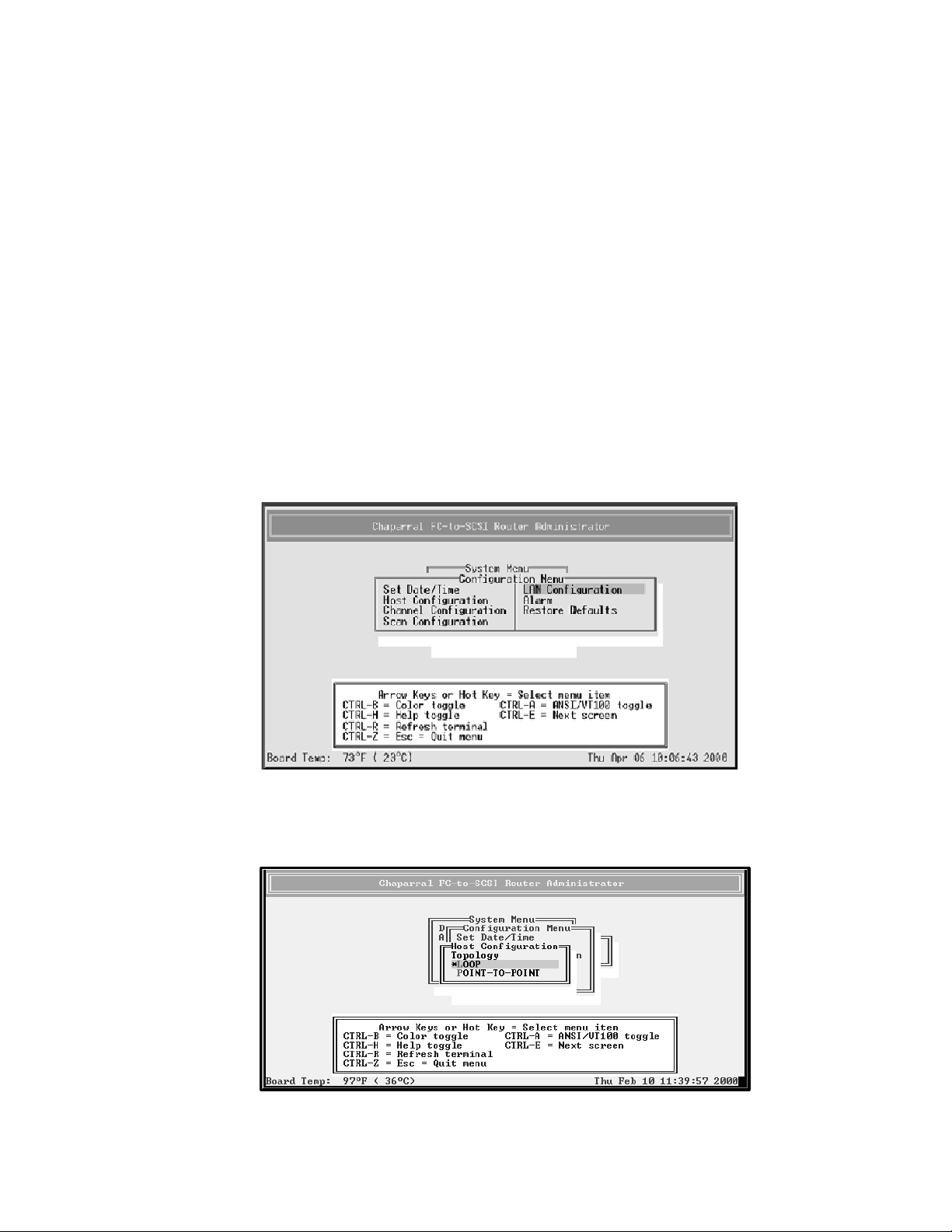
1 From the System Menu, select Configuration Menu and press Enter.
The Configuration Menu screen displays.
2 Select Host Configuration and press Enter.
The Host Configuration screen displays.
3-7
Page 36
VFS113 Rack/Desktop Model User’s Guide
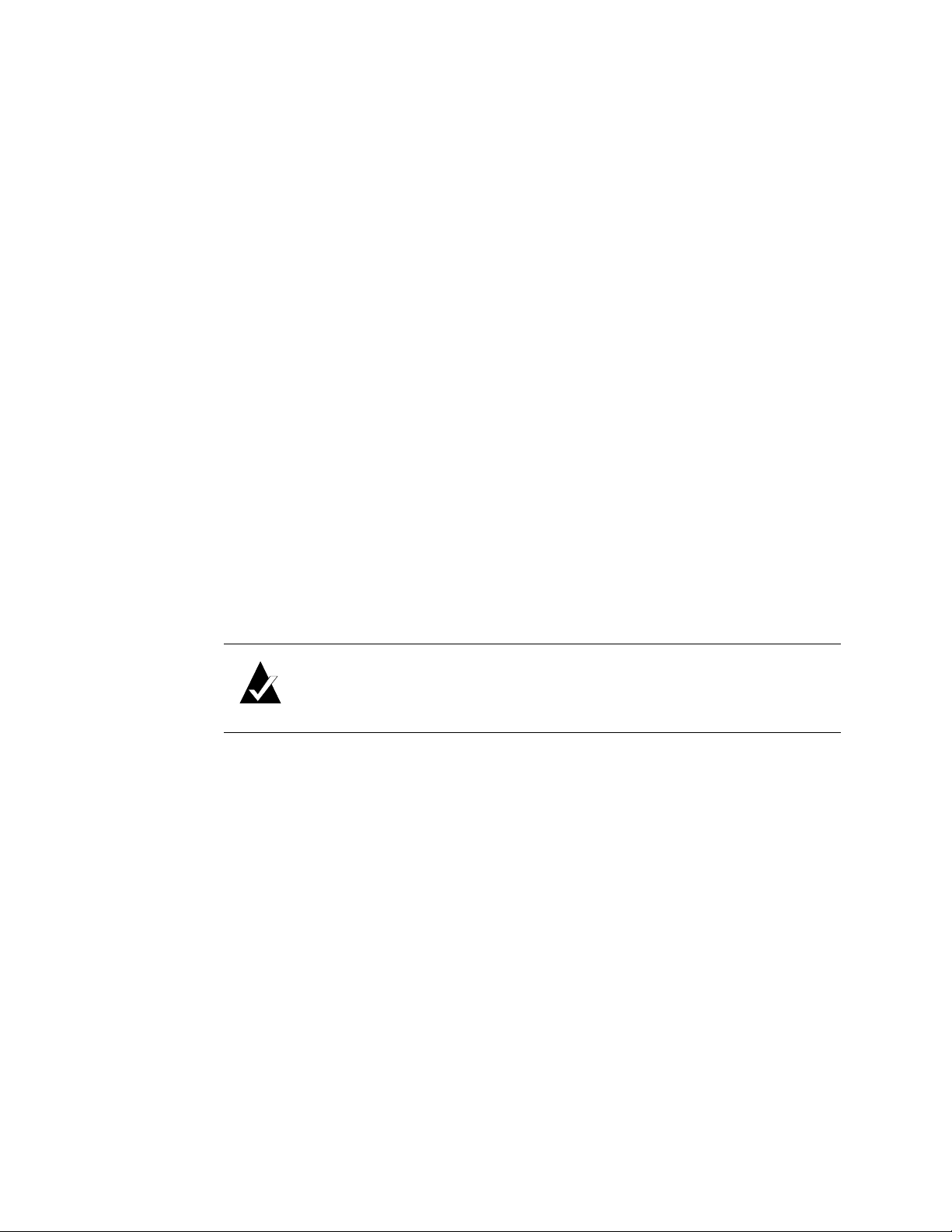
3 Select the Topology that matches your configuration and press Enter:
– LOOP—use this option for all configurations except when the router is connected
to a switch F-port. See Installation Configuration Examples on page 2-4.
– POINT-TO-POINT—use this option only when you connect the router to a
switch F-port. See Installation Configuration Examples on page 2-4.
If you selected LOOP, the Loop ID screen displays.
4 If the Loop ID screen displays, select the option or number you want to use and press
Enter.
For more information about these settings, see Changing the Router’s Loop ID on
page 3-8.
The Router LUN screen displays.
5 Select the option or number you want to use and press Enter.
For more information about these settings, see Changing the Router’s FC LUN on
page 3-10.
The system confirms that you want to make the changes.
6 Select Ye s and press Enter to make the changes.
The system confirms that the changes are made.
7 Press Enter to return to the Host Configuration Menu.
8 Reboot the router.
Note: If you change the topology, Loop ID, or router LUN, you must
reboot the router for the change to take effect. See Rebooting the Router on
page 3-19.
Changing the Router’s Loop ID
If the router is installed on an FC loop, you can change the router’s Loop ID to meet your
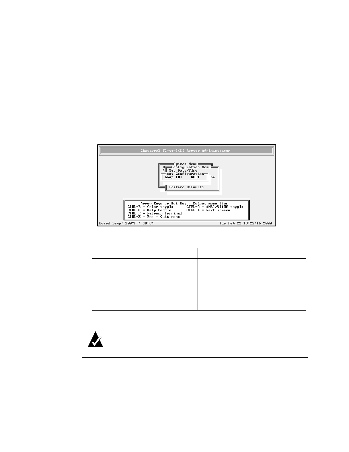
needs. You have two options for setting the Loop ID:
I SOFT—Use this setting if you do not care if the router’s Loop ID changes when you
power down and power up. This setting lets the FC loop initialization process
determine the Loop ID.
I Any number between 0 and 125—Select a specific number if you want the Loop ID to
stay the same after you power down and power up. The Router Administrator software
cannot tell you which Loop IDs are available. To be sure that you have successfully
assigned the Loop ID you want, check the Loop ID after you reboot the router. If the
router cannot get the specified Loop ID during the loop initialization process, it will
try to get a soft address.
3-8
Page 37
Configuring the Router
To change the Loop ID:
1 From the System Menu, select Configuration Menu and press Enter.
The Configuration Menu screen displays.
2 Select Host Configuration and press Enter.
The Host Configuration screen displays.
3 Select the topology you want and press Enter, or press Enter if the correct topology
is already selected.
The current setting is marked with an * next to it. For information about the topology
selection, see Selecting the Topology on page 3-7.
The Loop ID screen displays if Loop Topology was selected.
4 Select the option or number you want to use and press Enter.
To Do this
Let the FC loop initialization process
determine the Loop ID each time the
router powers up
Keep the same Loop ID for the router
at all times
Note: See Appendix A, Address and Device Mapping for more details on
how the value selected for the Loop ID will correspond to the AL_PA.
The Router LUN screen displays. The text inside the parenthesis ( ) shows the current
Router LUN.
I Select SOFT and press Enter.
This is the default setting
I Select the [Loop ID] you want to use
and press Enter.
This can be any number from 0 to 125.
3-9
Page 38
VFS113 Rack/Desktop Model User’s Guide
5 Press Enter.
If you want to change the router LUN, you can do so. See Changing the Router’s FC
LUN on page 3-10.
The system confirms that you want to make the change.
6 Select Ye s and press Enter to make the changes.
The system confirms that the changes are made.
7 Press Enter to return to the Configuration Menu.
8 Reboot the router.
Note: If you change the topology, Loop ID, or router LUN, you must
reboot the router for the change to take effect. See Rebooting the Router on
page 3-19.
9 If you entered a specific Loop ID, repeat steps 1 through 3 to see if the current setting
is what you entered.
Changing the Router’s FC LUN
You can change the router’s FC LUN to meet your needs. You can have three options for
setting the FC LUN:
I SOFT—Use this setting if you do not care if the router’s FC LUN changes when new
devices are added to the back end. This setting assigns the last available FC LUN to
the router.
I Any number between 00 and 63—Select a specific number if you want the router’s FC
LUN to stay the same when you add new devices and after you power down and
power up.
I NONE—Use this setting if you do not want the router to display as a device on the
host.
To change the LUN:
1 From the System Menu, select Configuration Menu and press Enter.
The Configuration Menu screen displays.
2 Select Host Configuration and press Enter.
The Host Configuration screen displays.
3 Select the topology you want and press Enter, or press Enter if the correct topology
is already selected.
3-10
The current setting is marked with an * next to it. For information about the topology
selection, see Selecting the Topology on page 3-7.
Page 39
Configuring the Router
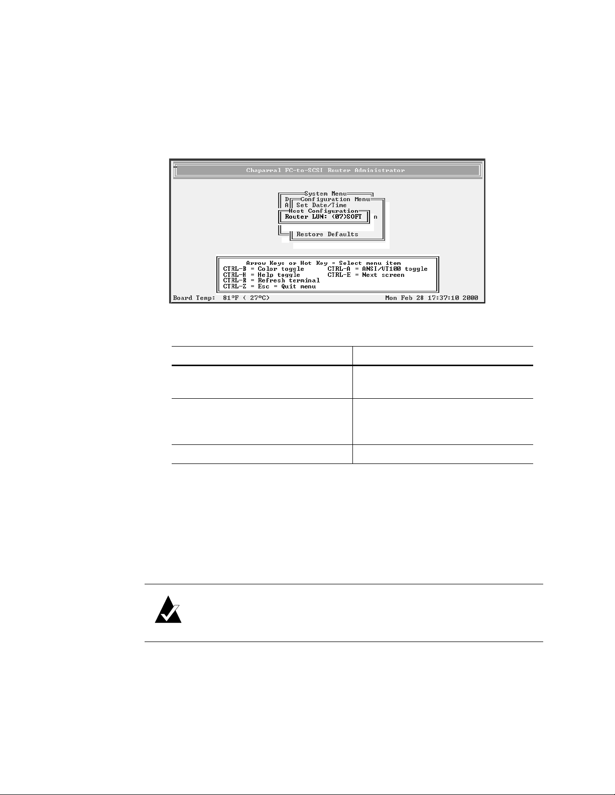
If you selected LOOP, the Loop ID screen displays. To display the Router LUN
screen, press Enter. If you want to change the Loop ID, you can do so. See Changing
the Router’s Loop ID on page 3-8.
If you selected POINT-TO-POINT, the Router LUN screen displays.
The text inside the parentheses ( ) shows the current Router LUN setting.
4 Select the option or number you want to use and press Enter.
To Do this
Let the router determine the its LUN
each time the it powers up
Keep the same LUN for the router at
all times
I Select SOFT and press Enter.
This is the default setting.
I Select the [LUN] you want to use
and press Enter.
This can be any number from 00 to 63.
Not assign the router an FC LUN I Select NONE and press Enter.
The system confirms that you want to make the change.
5 Select Ye s and press Enter to make the changes.
The system confirms that the changes are made.
6 Press Enter to return to the Configuration Menu.
7 Reboot the router.
Note: If you change the topology, Loop ID, or router LUN, you must
reboot the router for the change to take effect. See Rebooting the Router on
page 3-19.
8 If you entered a specific LUN, repeat steps 1 through 3 to see if the current router
LUN, inside the parentheses ( ), is what you entered.
9 If the LUN is not what you want, repeat steps 4 through 7.
3-11
Page 40
VFS113 Rack/Desktop Model User’s Guide
Changing the SCSI ID Assigned to Each Router Channel
The router assigns each of its SCSI channels one of the SCSI IDs (initiator IDs), leaving
15 SCSI IDs available for devices. You can change the SCSI ID assigned to each channel.
To change the SCSI ID assigned to a router channel:
1 From the System Menu, select Configuration Menu and press Enter.
The Configuration Menu screen displays.
2 Select Channel Configuration and press Enter.
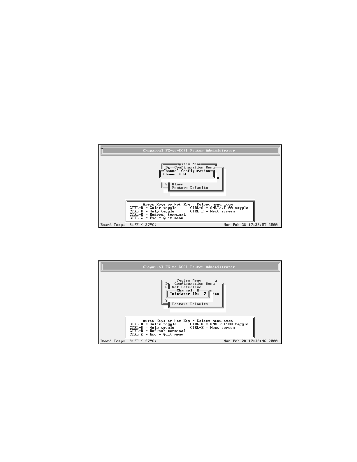
The Channel Configuration screen displays.
3 Select the channel whose SCSI ID you want to change and press Enter.
The Channel screen displays.
3-12
Page 41
Configuring the Router
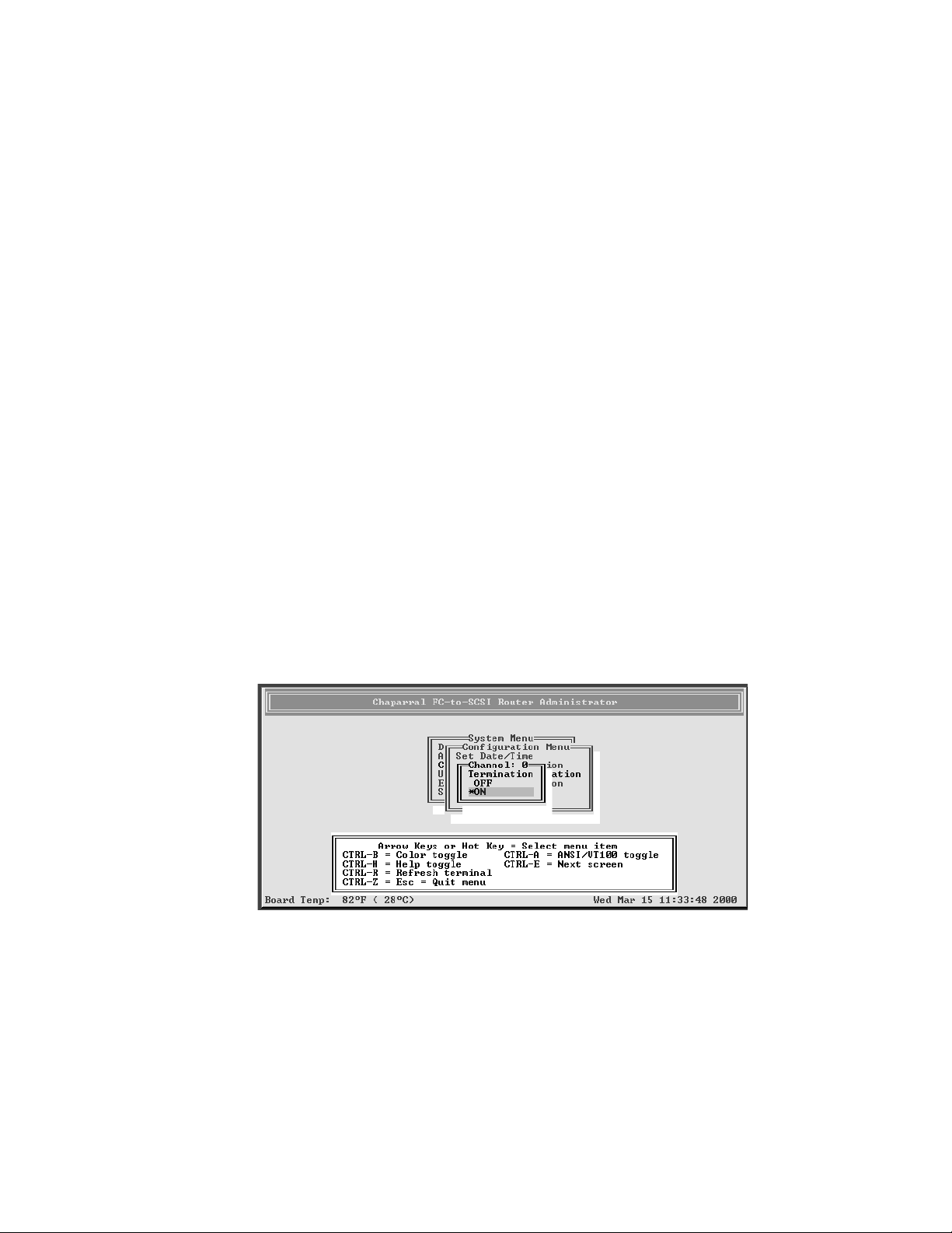
4 Select the SCSI ID (Initiator ID) you want to use for this channel and press Enter.
Depending the model you have, other screens may display.
The system confirms that you want to make the change.
5 Select Ye s and press Enter to make the changes.
The system confirms that the changes are made.
6 Press Enter to return to the Configuration Menu.
Disabling the Termination on an HVD Router
You can disable the router’s termination on the HVD model only; the termination on the
LVD model cannot be disabled. You would only want to disable termination if the router is
located in the middle of a SCSI bus.
To disable the termination:
1 From the System Menu, select Configuration Menu and press Enter.
The Configuration Menu screen displays.
2 Select Channel Configuration and press Enter.
The Channel Configuration screen displays.
3 Select the channel you want to change and press Enter.
You may need to change initiator IDs depending on the requirements of the device.
4 Select Termination and press Enter.
The Termination screen displays.
5 Select OFF and press Enter.
The system confirms that you want to make the change.
6 Select Ye s and press Enter to turn termination off.
The system confirms that the change is made.
7 Press Enter to return to the Configuration Menu.
3-13
Page 42
VFS113 Rack/Desktop Model User’s Guide
Setting the Date and Time
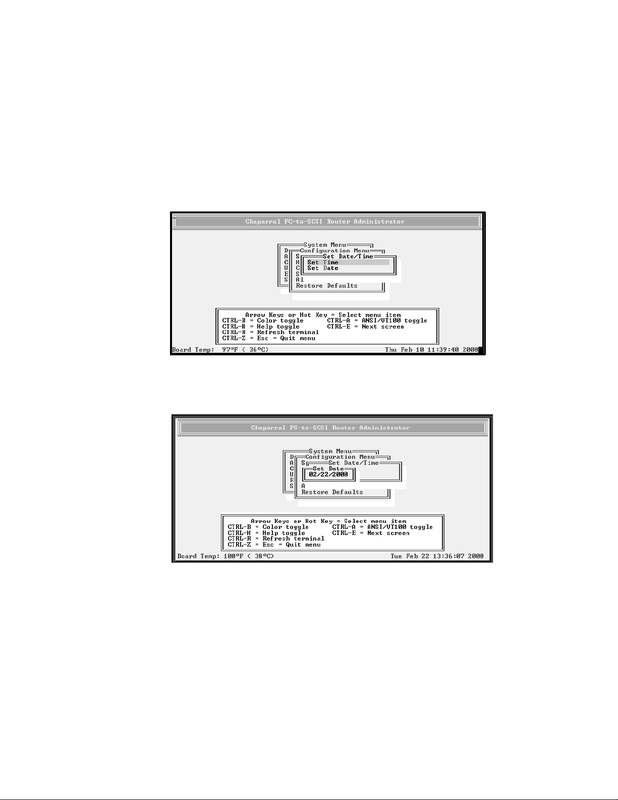
You can set the router’s date and time.
To set the router’s date:
1 From the System Menu, select Configuration Menu and press Enter.
The Configuration Menu screen displays.
2 Select Set Date/Time and press Enter.
The Set Date/Time screen displays.
3 Select Set Date and press Enter.
The Set Date screen displays.
4 Enter the date you want and press Enter.
Enter the date in the following format: MM/DD/YYYY.
The system confirms that you want to make the change.
5 Select Ye s and press Enter to make the changes.
The system confirms that the changes are made.
3-14
6 Press Enter to return to the Configuration Menu.
To set the router’s time:
1 From the System Menu, select Configuration Menu and press Enter.
Page 43
Configuring the Router
The Configuration Menu screen displays.
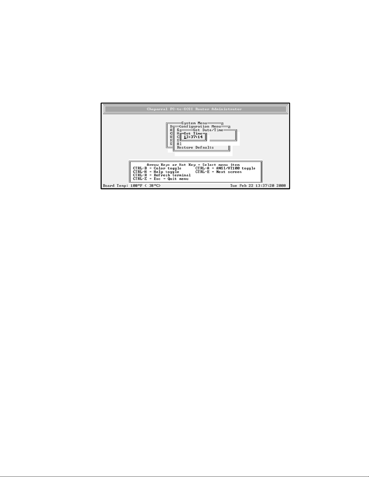
2 Select Set Date/Time and press Enter.
The Set Date/Time screen displays.
3 Select Set Time and press Enter.
The Set Time screen displays.
4 Enter the time you want and press Enter.
Enter the time in the following format: hh:mm:ss.
The system confirms that you want to make the change.
5 Select Ye s and press Enter to make the changes.
The system confirms that the changes are made.
6 Press Enter to return to the Configuration Menu.
Changing the Scan Delay
You can control how long the router waits before scanning its channels for devices. You
may want to change this setting if you have devices that take longer to come ready than the
router.
To change the scan delay:
1 From the System Menu, select Configuration Menu and press Enter.
The Configuration Menu screen displays.
3-15
Page 44
VFS113 Rack/Desktop Model User’s Guide
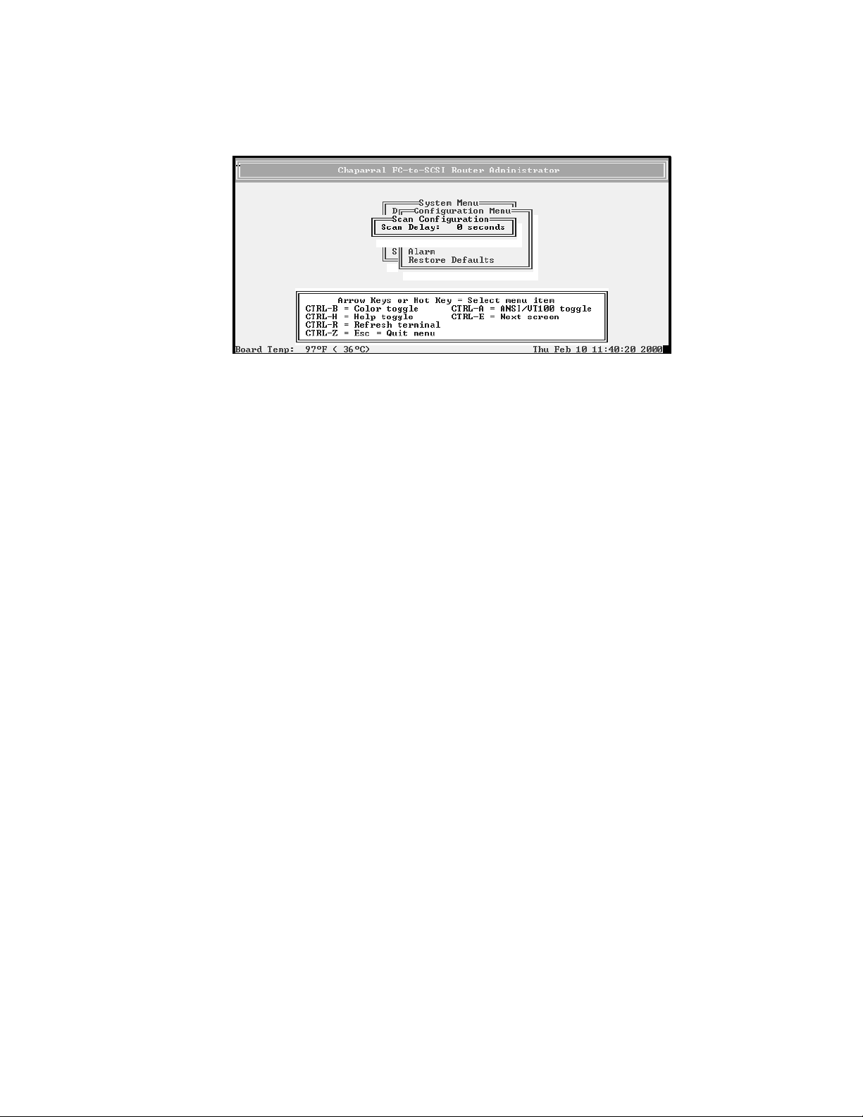
2 Select Scan Configuration and press Enter.
The Scan Configuration screen displays.
3 Select the number of seconds you want the router to wait and press Enter.
You can select any number between 0 and 255.
The system confirms that you want to make the changes.
4 Select Ye s and press Enter to make the changes.
The system confirms that the changes are made.
5 Press Enter to return to the Configuration Menu.
Enabling and Disabling the Alarm
You can enable or disable the audible alarm that sounds when the router becomes too hot
or detects low or high voltage. The alarm sounds a warning first. If the problem is not
resolved, the alarm sounds a shutdown alarm. The router will then no longer transmit data
until the problem is resolved.
The alarm conditions make the ST (status) light blink and also trigger an event message
that displays in the Router Administrator software window and in the event log. See
Displaying the Event Log on page 3-24.
3-16
Page 45

Configuring the Router
Table 3-3 shows the temperature and voltage thresholds for each alarm and what to do to
resolve the problem.
Table 3-3. Alarm thresholds
Alarm threshold What to do when the alarm sounds
CPU temperature
Warning—5°C and 65°C
Shutdown—0°C and 70°C
On-board temperature
Warning—5°C and 45°C
Shutdown—0°C and 50°C
VCC voltage
Warning—5V -3.5% and
+6.5%
Shutdown—5V -6.5% and
+10%
I Check the Router Administrator software to confirm
what the alarm means. See Accessing the Router
Administrator Software on page 3-1.
I Check that the fan is running and is not obstructed.
You can feel if the fan is running by placing your
hand on the rear panel of the router near the power
switch.
I Check the ambient temperature and lower it, if
needed. Ambient temperature should be less than
45°C.
I Same as above for the CPU temperature.
I Check the Router Administrator software to confirm
what the alarm means. See Accessing the Router
Administrator Software on page 3-1.
I If it is a warning alarm, let the router continue to
operate.
I If it is a shutdown alarm, turn off the power to the
router and send it for service.
12V voltage
Warning—12V -8% and
+8%
Shutdown—12V -10% and
+10%
I Same as above for the VCC voltage.
3-17
Page 46
VFS113 Rack/Desktop Model User’s Guide
To enable or disable the alarm:
1 From the System Menu, select Configuration Menu and press Enter.
The Configuration Menu screen displays.
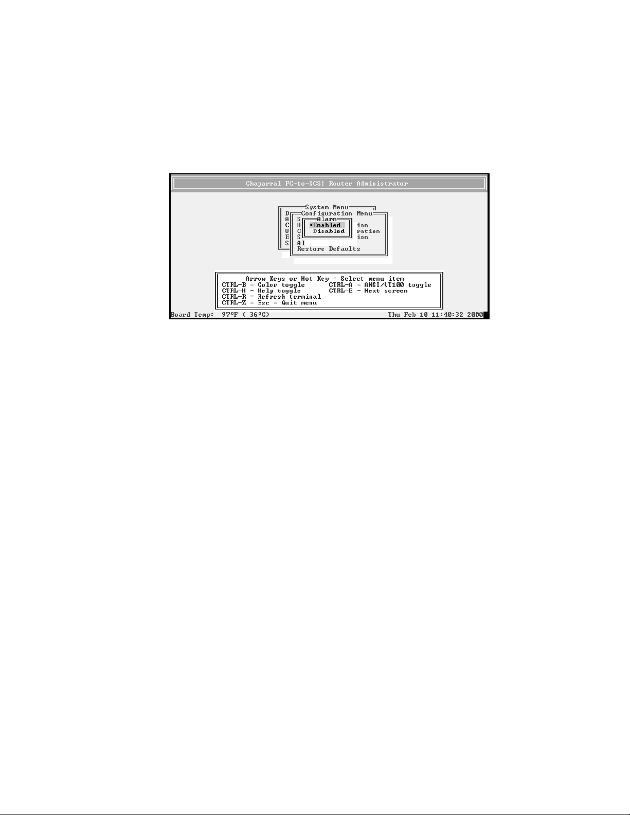
2 Select Alarm and press Enter.
The Alarm screen displays. The current setting is marked with an * next to it.
3 Select the option you want and press Enter.
The system confirms that the changes are made.
4 Press Enter to return to the Configuration Menu.
Restoring the Default Settings
You can restore all of the router’s default settings. You may want to do this if the router is
not working properly and you cannot determine why. This lets you then change the
settings that are critical to your configuration, specifically the topology.
For a table of the default settings, see Router Default Settings on page 2-12.
To restore the default settings:
1 From the System Menu, select Configuration Menu and press Enter.
The Configuration Menu screen displays.
3-18
Page 47

Configuring the Router
2 Select Restore Defaults and press Enter.
The Restore Defaults screen displays. The selected option is marked with an * next to it.
3 Select Ye s and press Enter to make the change.
The system confirms that the changes are made.
4 Press Enter to return to the Configuration Menu.
Rebooting the Router
You must reboot the router after you change the topology, Loop ID, or router LUN. You
should also reboot the router when you connect new devices.
To reboot the router:
1 From the System Menu, select Shutdown/Restart and press Enter.
The system confirms that you want to shut down.
2 Select Ye s and press Enter.
The system confirms that it has shut down.
3 Press Enter to reboot.
The system performs its self-test. When you see the Router Administrator initial
screen, the router is ready. See Accessing the Router Administrator Software on
page 3-1.
4 If you are connected via Telnet, disconnect and reconnect the Telnet session.
3-19
Page 48
VFS113 Rack/Desktop Model User’s Guide
Changing and Displaying Device Information
You can change and display information about the devices connected to the router using
the Router Administrator. You can:
I Change the mapping mode (AUTO or FIXED) (page 3-20)
I Change device addresses (page 3-21)
I Display the devices attached to the router (page 3-23)
I Display the FC-to-SCSI address map (page 3-23)
Changing the Mapping Mode (AUTO or FIXED)
You can change how the router maps the addresses of the devices on the SCSI channels to
FC LUNs. You have two options for the mapping mode, which affects all three SCSI
channels on the VFS113:
I AUTO—lets the router assign an FC LUN to each device anytime you power up the
router. The router maps sequentially as it scans the channels and discovers devices
(devices are discovered by channel, lowest SCSI ID and LUN first). Devices are
mapped to FC LUNs, starting from LUN 0 to LUN 63 (64 LUNs are supported).
I FIXED—locks the current mapping for each device. This reserves the devices’ same
FC LUN over power cycles (SCSI channel:target:LUN combination), even when you
power down and power up the router. The router also retains the mapping, if the
devices are added, moved, or removed. The FIXED mode is recommended for
environments where device configuration may change and a FIXED mapping from
the application to the target devices is required. Devices added after selecting FIXED
will be automatically mapped to an available FC LUN.
For example, either a disk drive or a tape drive would map to the same FC LUN if the
disk drive at a particular SCSI channel:target:LUN is replaced with a tape drive at the
same SCSI channel:target:LUN.
To change the mapping mode:
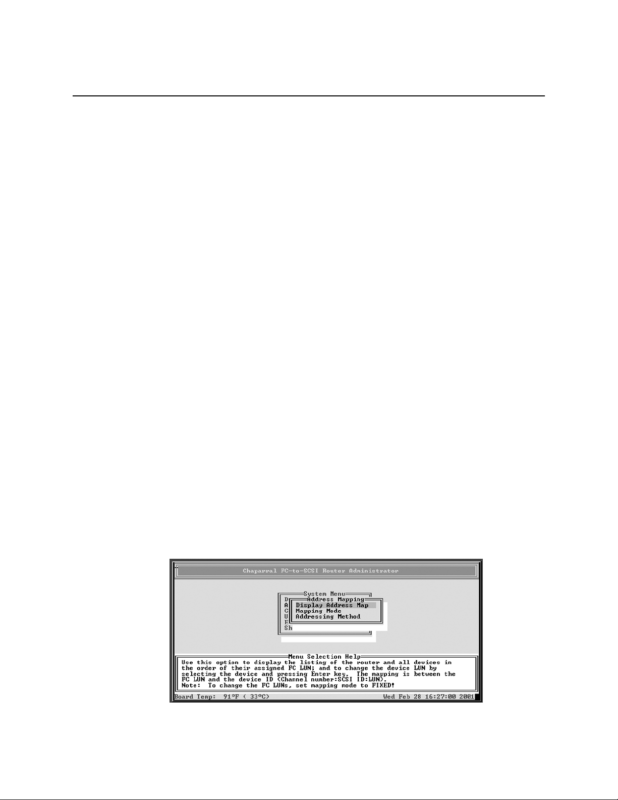
1 From the System Menu, select Address Mapping and press Enter.
The Address Mapping screen displays.
3-20
Page 49
Configuring the Router
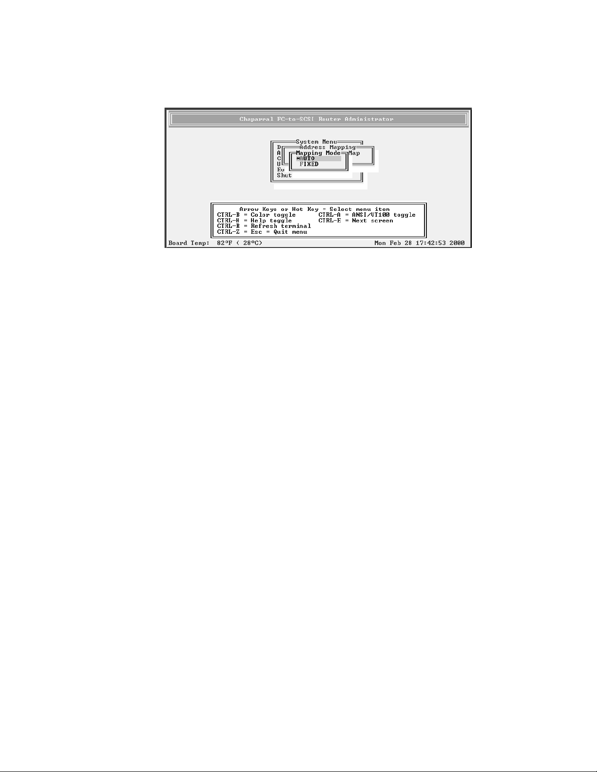
2 Select Mapping Mode press Enter.
The Mapping Mode screen displays. The current setting is marked with an * next to it.
3 Select the option you want and press Enter:
AUTO—lets the router assign the FC LUN to each device anytime you power up the
router.
FIXED—tells the router to keep the same FC LUN as currently assigned for each
device. This reserves the same FC LUN for each device, even when you power down
and power up the router. The router retains the FC LUN, even if the device is no
longer connected.
The system confirms that the changes are made.
4 Press Enter to return to the Address Mapping screen.
Changing Device Addresses (FC LUNs)
You can change the FC LUN for any device connected to the router. You can only change
the FC LUNs when the address mapping mode is set to FIXED. As long as you stay in
FIXED mode, all FC LUNs you change will be retained even if the device or router is
powered off and back on or if the device is removed and reconnected.
You can set the FC LUN for devices to any number between 00 and 63 by selecting the FC
LUN that you want the device to map to. You cannot select the same FC LUN as the
router’s LUN.
When in FIXED mode, the router will discover any new devices or existing devices that
were removed and reconnected to a different location. These newly discovered devices
will be in AUTO mode and will be assigned an FC LUN by the router. You can change
these FC LUNs by following the steps below.
If you assign an FC LUN that is already in use, the FC LUNs for the two devices are
swapped. For example, if device A has LUN 01 and device B has LUN 03, and you assign
03 to device A, the LUN for device B becomes 01.
For additional information about address mapping, see Appendix A, Address and Device
Mapping.
3-21
Page 50
VFS113 Rack/Desktop Model User’s Guide
To change the device FC LUNs:
1 Set the address mode to FIXED.
See Changing the Mapping Mode (AUTO or FIXED) on page 3-20.
2 From the System Menu, select Address Mapping and press Enter.
The Address Mapping screen displays.
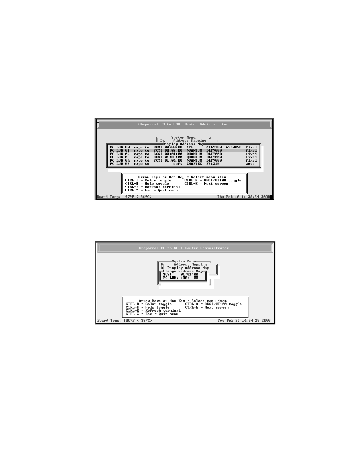
3 Select Display Address Map press Enter.
The Display Address Map screen displays.
4 Select the device whose LUN you want to change and press Enter.
The Change Address Map screen displays. The text inside the parentheses ( ) shows
the current FC LUN
5 Select the FC LUN number you want to use for this device and press Enter.
You can select any number between 00 and 63.
The system confirms that you want to make the changes.
6 Select Ye s and press Enter to make the changes.
3-22
The system confirms that the changes are made.
7 Press Enter to return to the Address Mapping screen.
Page 51
Configuring the Router
Displaying the Devices Connected to the Router
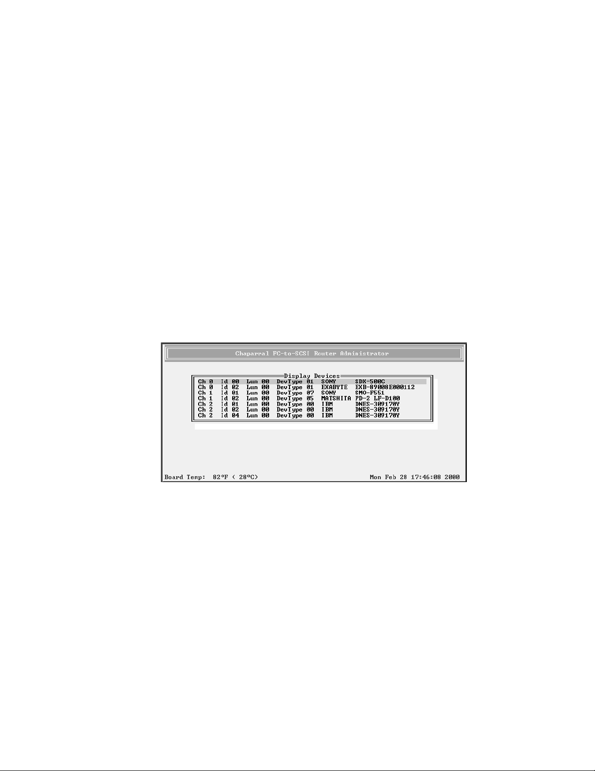
You can display a list of the SCSI devices connected to the router. Currently, the list only
includes the first 15 devices on each channel. To display a list of all devices, see
Displaying the FC-to-SCSI Address Map on page 3-23.
The list includes the following information for each device:
I SCSI channel number
I SCSI ID
I LUN
I Device type number (from the SCSI inquiry data)
I Bytes 8 through 31 of the standard SCSI inquiry data, which normally includes:
– Vendor ID
– Product ID
To display the devices connected to the router:
1 From the System Menu, select Display Devices and press Enter.
The Display Devices screen displays.
2 Press Esc to return to the System Menu.
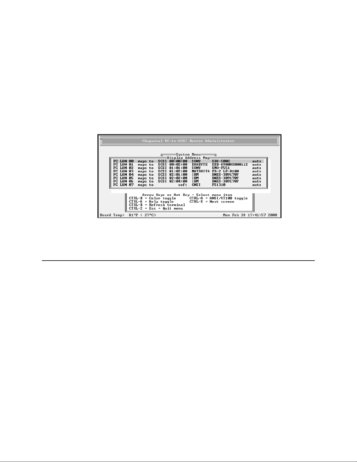
Displaying the FC-to-SCSI Address Map
You can display the FC-to-SCSI address map for all of the SCSI devices connected to the
router. The address map includes the following information for each device:
I FC LUN
I Device ID (Channel number:SCSI ID:LUN)
I Bytes 8 through 35 of the standard SCSI inquiry data, which normally includes:
– Vendor ID
– Product ID
I Mapping mode
3-23
Page 52
VFS113 Rack/Desktop Model User’s Guide
The address map lists devices in ascending order based on the FC LUN, including the
router itself if it has an FC LUN assigned to it.
For additional information about address mapping, see Appendix A, Address and Device
Mapping.
To display the address map:
1 From the System Menu, select Address Mapping and press Enter.
The Address Mapping screen displays.
2 Select Display Address Map press Enter.
The Display Address Map screen displays.
3 Press Esc to return to the Address Mapping screen.
Displaying Router Information
You can display important information about the router using the Router Administrator,
including:
I Event log (see page 3-24)
I Hardware and configuration information (see page 3-27)
I Router’s LUN (see page 3-30)
Displaying the Event Log
The router’s event log contains important information about the status of the router. Below
is a list of the events included in the log.
I Restore defaults
I Config changed
I Cntlr params set
I Router shutdown
3-24
I Power up
Page 53
Configuring the Router
I Firmware update
I Temperature warning
I Temperature failure (this leads to a shutdown of router which is logged as a shutdown)
I Voltage warning
I Voltage failure (this leads to a shutdown of router which is logged as a shutdown)
You should check the log regularly. The event log stores the most recent 400 events.
Events are numbered from 001 to 999. The numbering wraps back to 001 after reaching
999.
Note: If you are having a problem with the router, check the event log
before calling technical support. Event messages may let you resolve the
problem without calling.
You can view the event log two ways:
I One event at a time, most recent event first
I Full page of events at a time
You can also capture the text to a file. See Event Log File Capture on page 4-7.
To display one event at a time:
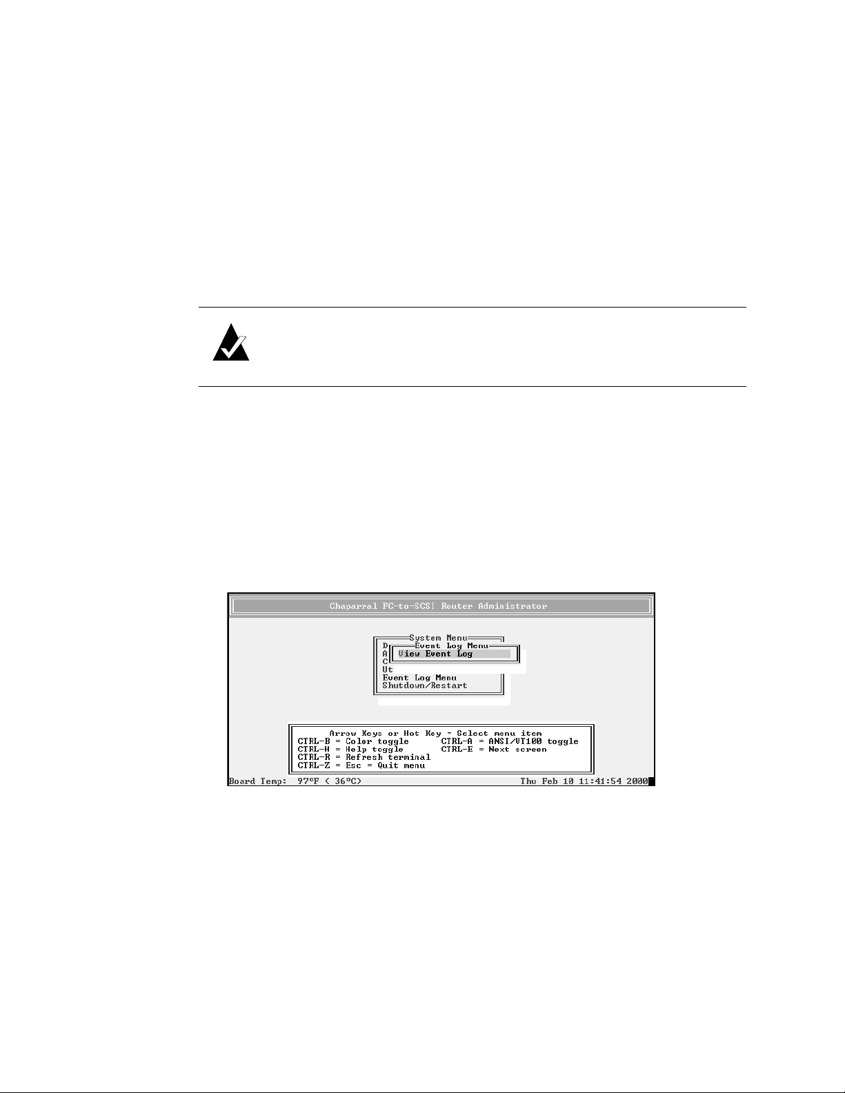
1 From the System Menu, select Event Log Menu and press Enter.
The Event Log Menu screen displays.
3-25
Page 54
VFS113 Rack/Desktop Model User’s Guide
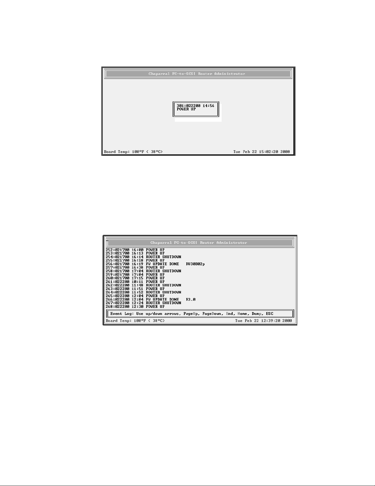
2 Select View Event Log and press Enter.
The Event Log screen displays the last event that occurred.
3 Press ↑ to see the previous event.
You can continue to view earlier events by pressing
↑.
4 Press Esc to return to the Event Log Menu.
To display a full page of events:
1 From anywhere in the Router Administrator software, press Ctrl-e.
The first screen of events from the event log displays.
2 Press d to page down or u to page up in the log.
3 Press Esc to return to where you started from.
3-26
Page 55

Configuring the Router
Displaying Hardware and Configuration Information
You can display the router’s hardware and configuration information. This is where you
can see what version of the firmware you have. Chaparral technical support personnel may
also request this information.
You can display the hardware and configuration information two ways:
I Hardware information only
I Hardware and configuration information
Table 3-4 lists the configuration information that is available.
Table 3-4. Configuration information
Group Field What displays Field What displays
HOST Topology Loop or Point-to-Point
based on the topology
set in the Router
Administrator software.
If set to Loop, the router
detects if it is attached
to a public loop (router
is attached to the FLport of a switch) or a
private loop.
CHAN 0
CHAN 1
CHAN 2
Node WWN FC World Wide Name
for node.
Port WWN FC World Wide Name
for port.
FC Addr 24-bit FC address or
None if the FC link is
not active.
Loop ID, if the
topology is
LOOP.
Router LUN SOFT, NONE, or
Initiator ID SCSI ID of router on
Termination Hardware setting: ON
SOFT or a specific
number as set in the
Router Administrator
software.
specific number as set in
the Router
Administrator software.
Channel 0 as set in the
Router Administrator
software.
or OFF.
AL_PA, if
the
topology is
LOOP.
Current Currently assigned
Current Currently assigned
Ultra/U2 Hardware runs as
Term
Power
Currently assigned
value or None if the
FC link is not
active.
value if the
topology is LOOP,
or Inactive if the FC
link is not active.
value or Inactive if
the Router LUN is
set to NONE.
Ultra2.
Hardware supplies
termination power.
3-27
Page 56
VFS113 Rack/Desktop Model User’s Guide
Table 3-4. Configuration information (Continued)
Group Field What displays Field What displays
ROUTER Alarm ENABLED or
DISABLED as set in the
Router Administrator
software.
CAPI Version Version of the
Configuration
Application
Programming Interface.
FC LIB Version Version of the FC
library.
To display hardware information only:
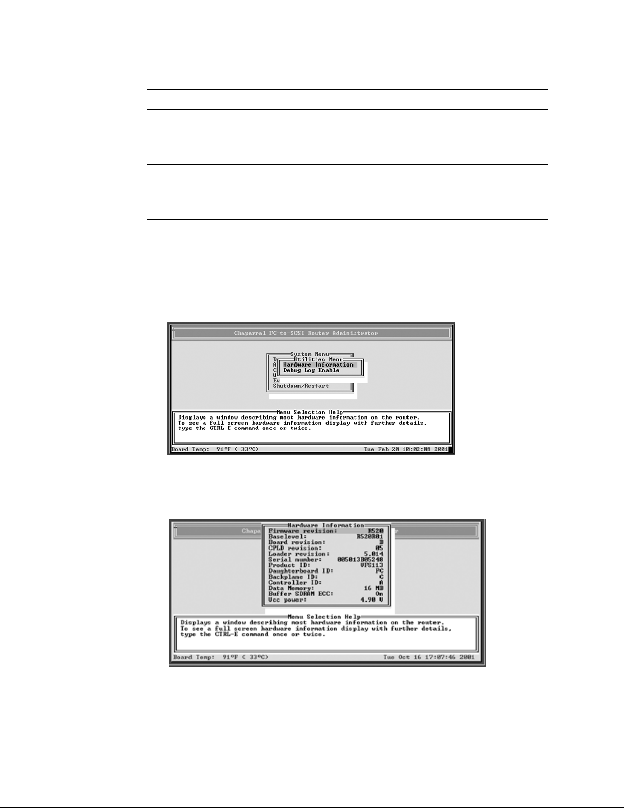
1 From the System Menu, select Utilities Menu and press Enter.
The Utilities Menu screen displays.
3-28
2 Select Hardware Information and press Enter.
The Hardware Information screen displays.
3 Press Esc to return to the Configuration Menu.
Page 57
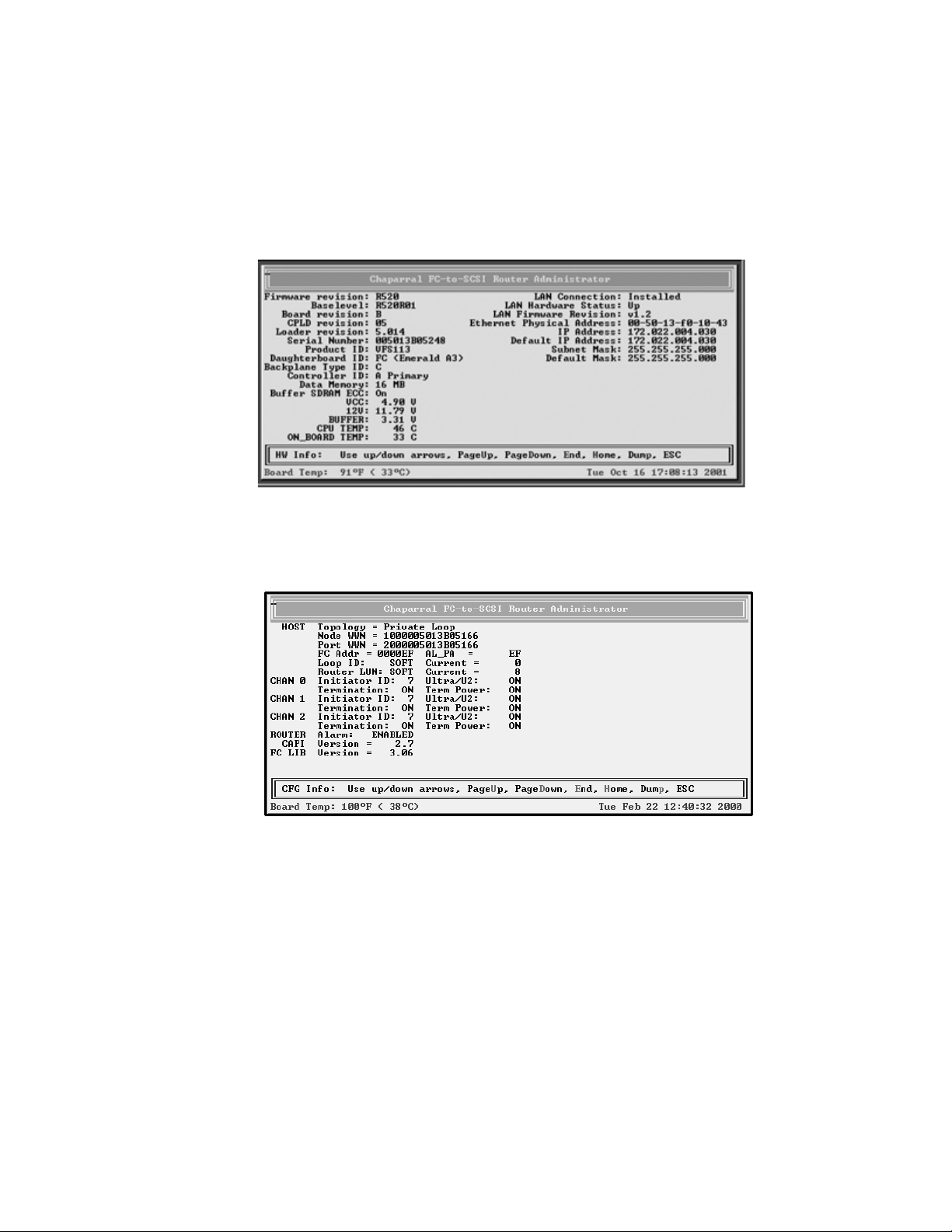
Configuring the Router
To display hardware and configuration information:
1 From anywhere in the Router Administrator software, press Ctrl-e.
The first screen of events from the event log displays.
2 Press Ctrl-e again
The Hardware Information screen displays.
3 Press Ctrl-e again.
The Configuration Information screen displays.
4 Press Esc to return to where you started from.
3-29
Page 58
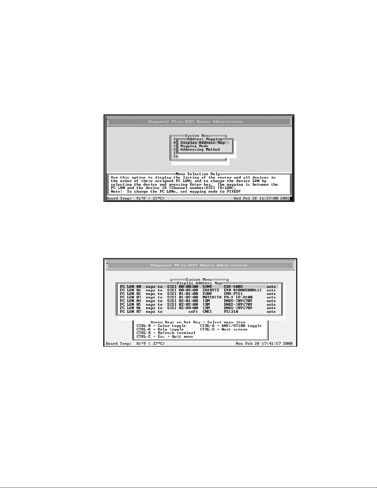
VFS113 Rack/Desktop Model User’s Guide
Displaying the Router’s FC LUN
You can display the router’s FC LUN and the FC LUNs of each device connected to the
router.
To display the router’s LUN:
1 From the System Menu, select Address Mapping and press Enter.
The Address Mapping screen displays.
2 Select Display Address Map and press Enter.
The Display Address Map screen displays listing the router and all devices in the
order of their assigned FC LUN. In the example screen below, the router is the last
item.
3 Press d to page down or u to page up in the list.
4 Press Esc to return to the Address Mapping screen.
3-30
Page 59

Configuring the Router
Upgrading Firmware
You can upgrade the firmware for the router and the Ethernet card in the router.
Information regarding the latest release of firmware and firmware updates is available
from the Chaparral Web site (www.chaparralnet.com/support). Contact Chaparral
technical support for the password to access the firmware updates.
Upgrading the Router’s Firmware
You use the Flash Utility to download new firmware (.fla file) for your router, to autodetect your VT-100/ANSI terminal baud rate, and to run on-board diagnostics. The Flash
Utility is resident in the embedded firmware of the router.
You access the Flash Utility using a computer with VT-100/ANSI terminal emulator
software, such as HyperTerminal, connected to the router through the serial RS-232
interface. The router auto-detects the baud rate when you hold down the space bar on the
computer while powering-on the router. Valid baud rates are 9,600, 19,200, 38,400, 57,600
and 115,200. The default baud rate is 115,200 and is recommended to expedite the
download process.
To upgrade the router’s firmware:
1 Call Chaparral technical support for information about downloading the firmware
updates.
See Chaparral Technical Support on page 4-1.
2 From the computer connected to the router, access the Router Administrator
software.
See Accessing the Router Administrator Software on page 3-1.
3 From the System Menu, select Shutdown/Restart and press Enter.
The system confirms that you want to shut down.
4 Select Ye s and press Enter.
The system confirms that it has shut down.
5 Press Enter to reboot.
3-31
Page 60
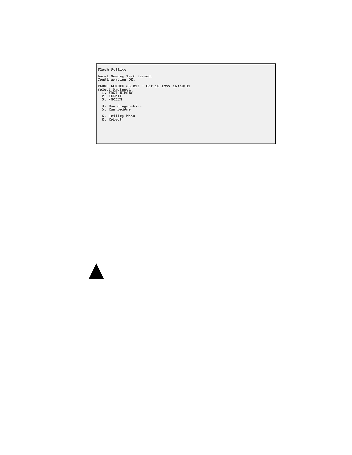
VFS113 Rack/Desktop Model User’s Guide
6 While the router reboots, hold down the space bar on your keyboard.
The Flash Utility screen displays.
7 Press the number on your keyboard that corresponds to the protocol you want to use
to transfer the firmware upgrade file from your computer to the router.
We recommend using the KERMIT protocol.
The system shows that it is ready to use KERMIT.
8 Using your terminal emulator software, send the .fla file using KERMIT.
If you are using HyperTerminal, select Transfer | Send File, navigate to where the
firmware update file is located, select it, and click Open. Select the same Protocol
from the drop-down list as you selected from the Flash Utility screen. Click Send.
The file transfers. The system displays messages showing that it is flashing the code
and rebooting the router.
!
Caution: Do not interrupt the power when transferring the new firmware.
3-32
Page 61

Configuring the Router
Upgrading the Ethernet Card’s Firmware
You can also update the firmware for the Ethernet card inside the router. The firmware is
contained in a .bin file.
To upgrade the Ethernet card’s firmware:
1 Call Chaparral technical support for information about downloading the firmware
updates.
See Chaparral Technical Support on page 4-1
2 From the computer connected to the router, access the DOS window.
3 At the DOS prompt change to the directory where you downloaded
the .bin file.
4 Enter:
FTP [router’s IP address]
5 At the User prompt enter:
flash
❒
6 At the Password prompt enter:
flash
7 At the FTP prompt enter:
hash
8 At the FTP prompt enter:
put [bin file name] flash
You will see the downloading progress displayed on the screen.
9 When you see the rebooting message wait 60 seconds.
3-33
Page 62

VFS113 Rack/Desktop Model User’s Guide
3-34
Page 63

Resolutions to common problems you may encounter are described in the following
sections. This section describes troubleshooting using the RS-232 serial port.
Caution: Do not remove the router’s cover. The router has no user-
!
serviceable parts. Removing the cover will void the warranty.
Chaparral Technical Support
4
Troubleshooting
For assistance configuring and using your Chaparral product, contact your
authorized distributor or send an e-mail to Chaparral technical support at
Problems During Bootup
The following section describes problems you might encounter during Power On Self-Test
(POST) or during bootup and explains how to resolve those problems.
Problem: Router failed the onboard memory test.
Solution: When this failure occurs, it means the internal CPU memory failed. Replace the
router to correct the problem.
Problem: System hangs at Loading Bridge during Flash Loader Menu.
Solution: Reflash the firmware to ensure you are using the latest version. See Upgrading
Firmware on page 3-31. If you cannot update the firmware or if the updated firmware
does not correct the problem, replace the router.
Problem: One of the POST diagnostic tests failed.
Solution: Use the information in Table 4-1 to find solutions to a particular diagnostic
failure. First confirm any failure you may encounter by running the individual test from
the Diagnostics menu. See Using the Loader Diagnostics Menu on page 4-6.
4-1
Page 64

VFS113 Rack/Desktop Model User’s Guide
Table 4-1. POST diagnostic errors and solutions
Diagnostic Failure Solutions
Default hardware register Replace the router.
Default chip set register Replace the router.
Voltage/temperature 1. Check for thermal problems in the environment.
2. Check any airflow obstruction.
3. Replace the router.
Local DRAM memory test Replace the router.
LVDS BIST Replace the router.
PCI configuration
Replace the router.
verification
SCSI device scratch RAM Replace the router.
2
C chip Replace the router.
I
Buffer memory Replace the router.
Programmable interval
Replace the router.
timer
Real-time clock chip Replace the router.
Fibre Channel interface test 1. Check the firmware to make sure it matches the
hardware configuration. See Upgrading Firmware on
page 3-31 if you need to update the firmware.
2. Replace the router.
Note: POST diagnostics only display a voltage/temperature warning or
failure. It does not result in an error. Voltage/temperature failures cause
router shutdown after the router has booted.
4-2
Problem: The system hangs after the “All diagnostic tests passed” message or while
scanning devices.
Solution: Follow these steps to resolve the problem:
1 Verify there are no SCSI address conflicts.
2 Check the connected SCSI devices to make sure everything is properly connected
and SCSI termination is correct. See Restoring the Default Configuration Through
the Flash Utility.
3 If the devices work properly, replace the router.
Page 65
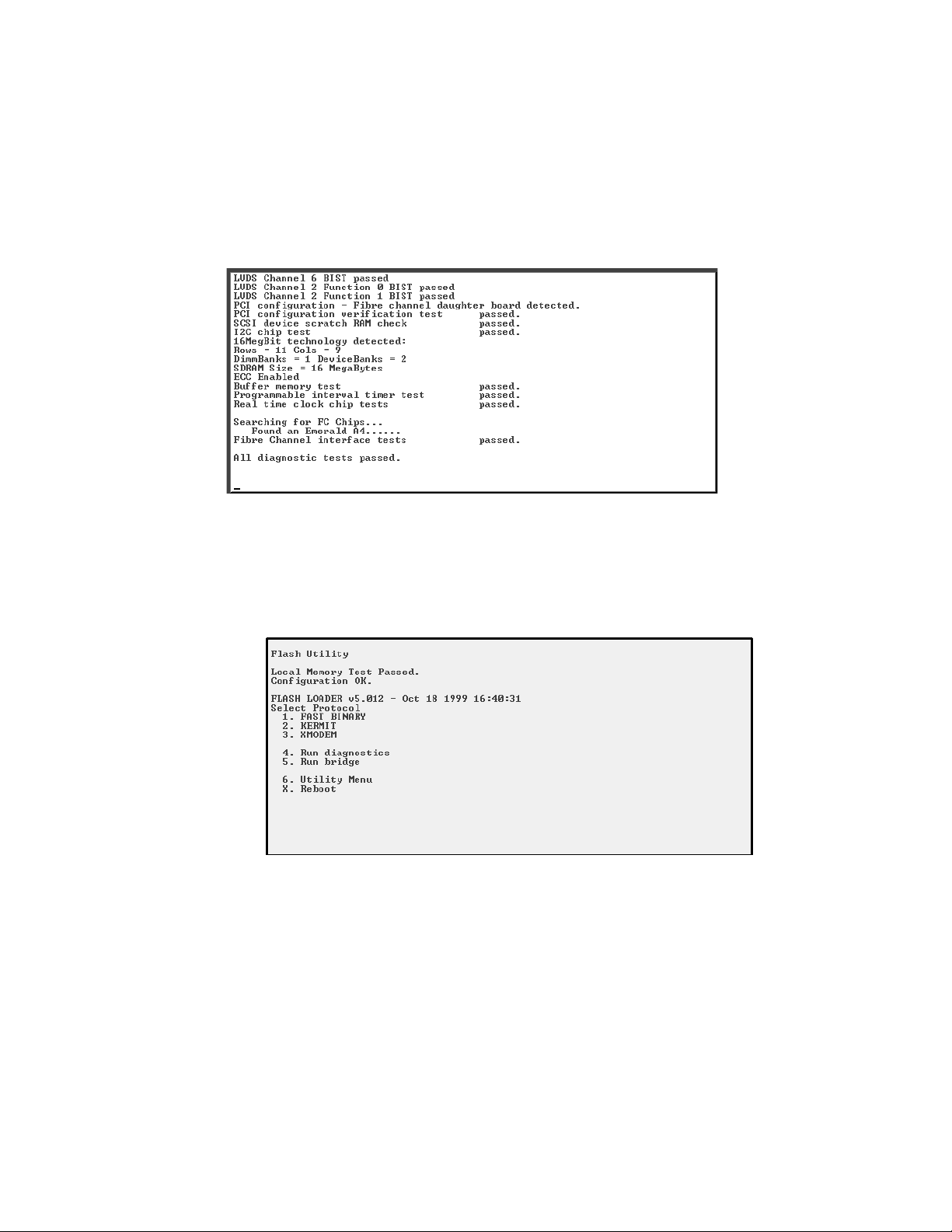
Troubleshooting
Restoring the Default Configuration Through the Flash Utility
You can clear the router configuration and restore all router default settings without
accessing the Router Administrator software. You may want to do this if the router is not
working properly or the system hangs after the “All diagnostic tests passed” message, as
shown on the following screen.
To restore the default configuration:
1 After powering on the system, hold down the space bar to prevent the system from
rebooting.
The Flash Utility screen displays.
4-3
Page 66
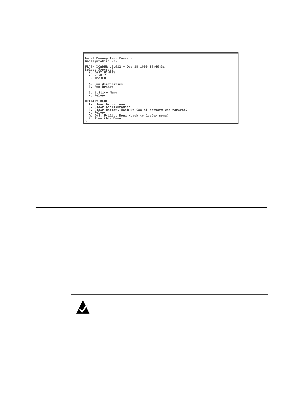
VFS113 Rack/Desktop Model User’s Guide
2 Select 6. Utility Menu and press Enter.
The Utility Menu screen displays.
3 Select 2. Clear Configuration and press Enter.
4 The system confirms that you want to make the change. Enter Y to confirm and press
Enter to clear the configurations.
5 The system confirms that the changes are made.
6 Press q to quit the Utility Menu.
7 Select 5. Run Bridge to verify the configurations have been cleared.
Terminal Emulator and COM Port Problems
Problem: Screen continuously puts out garbage characters.
Solution: The likely cause of this problem is a baud rate mismatch between the terminal
emulator and the router. The default baud rate is 115,200 bps. Follow these steps if you set
your terminal emulator to this rate and still get garbage characters:
1 Turn off the power to the router.
2 Press the spacebar of your terminal emulator.
3 Turn on the power while continuing to press the spacebar. This will allow the router
to autodetect the baud rate setting.
4 When the Flash Utility appears, select 5. Run Bridge to continue to boot the router.
Note: Some terminal emulators don’t immediately change to the new
baud rate settings, and you have to exit and restart the emulator to use the
new settings.
4-4
Page 67

Troubleshooting
Problem: Nothing is displayed on the terminal emulator.
Solution: The probable cause of this problem is your terminal emulator software is not
configured correctly.
Problem: Screen is updated, but won’t respond to keystrokes.
Solution:
1 Check that all the cables are connected properly.
2 Make sure the E/S switch is on S if you are trying to use the serial port.
3 Check that the correct COM port is enabled and configured.
For the COM port settings, see Connecting to the RS-232 Port on page 2-9.
4 Check that your terminal emulator software is configured properly.
5 Contact your authorized Chaparral distributor.
Problem: Screen looks correct, but clock is not being updated.
Solution: Check to be sure that router is still powered on. If you are using XON/XOFF,
press Ctrl-q.
Problem: Screen is updated and menus appear right, but boxes around menus look
incorrect.
Solution: Try a different font in your terminal emulator program, such as HyperTerminal.
If you cannot find a font that looks correct, set ASCII Display to Yes in the Display
options item of the Configuration menu.
Device SCSI Channel Problems
Problem: Not all drives connected to the router device channels are displayed during
boot, or the router hangs during display of connected drives and never reaches the Router
Administrator screen.
Solution: Check your JBOD or tape library documentation to be sure that the device is
properly configured. If your device supports removable drives, check the drive shuttles to
be sure that the power connectors, SCSI connectors, and SCSI ID connectors are properly
seated. Check termination and SCSI ID assignment.
Note: If the router is an HVD model, check the router termination settings
for all channels.
4-5
Page 68
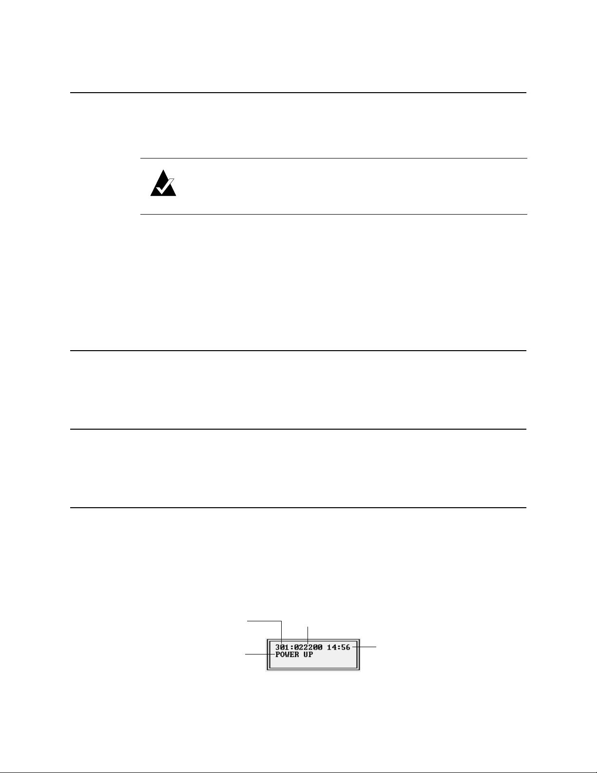
VFS113 Rack/Desktop Model User’s Guide
Router is Not Responding
Problem: The router is turned on and connected, but is not working properly and its LED
lights are not lit.
Solution: Replace the fuse.
Note: Be sure to use an F2H, 250V fuse.
1 Insert a small flat-blade screwdriver under the tab where the fuse is located and pull
out the fuse and fuse box.
See Figure 2-9 on page 2-7.
2 Remove the spare fuse from the box and replace the old fuse.
3 Reinstall the fuse and fuse box.
Using the Loader Diagnostics Menu
If the Power-On Self Test shows any errors, these diagnostics may help determine the
cause. Contact Chaparral technical support for assistance.
Using the Loader Utility Menu
This menu lets you perform low-level maintenance tasks. Contact Chaparral technical
support for assistance.
Event Logs
There are two different ways to view Event Logs.
To view events one at a time:
1 Select Event Log Menu from the System menu.
2 Select View Event Log from Event Log Menu.
Event Number
Date
4-6
Type of Event
Time
Page 69

Troubleshooting
Note: Event numbers restart at 000 after 999 events have been logged.
3 Use the ↑ and ↓ keys to browse through the list of events.
To view a whole screen of events at once follow these steps:
1 Type Ctrl-e to switch screens until the Event Log screen appears (the text “Event
Log” is located in the lower left corner of the screen).
2 Use this screen to view multiple events simultaneously.
↑ and ↓ keys allow you to scroll.
The
u moves the screen up a page.
d moves the screen down a page.
e moves to the last event at the end of the list.
h moves to the first event at the beginning of the list.
p dumps the entire Event Log to the screen. This is used for capturing an Event Log
file (see below).
Event Log File Capture
To capture the Event Log File follow these steps (Hyperterm is used as an example
terminal):
1 With Hyperterm up and running as your RS-232 interface terminal, press Ctrl-e until
Event Log is displays.
2 Select Transf er from the menu bar at the top.
3 Select Capture Text.
4 Enter the path and file name.
5 Select Start.
6 Press p on the keyboard and to begin the capture.
7 Select Transf er from the menu bar at the top.
8 Select Capture Text.
9 Select Stop.
Your file can now be attached to an e-mail message to be sent to customer support.
4-7
Page 70
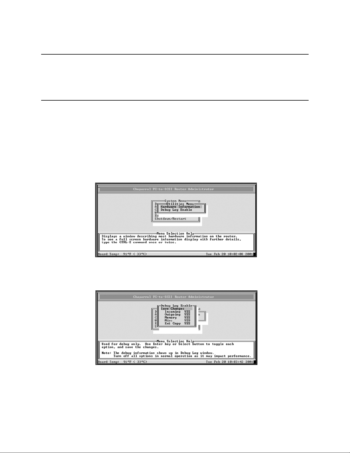
VFS113 Rack/Desktop Model User’s Guide
Voltage and Temperature Errors and Warnings
Most voltage and temperature errors occur due to environmental conditions. See Table 1-1
on page 1-4 for environmental specifications.
Setting Up Debug Logging
The router has a debug log that you can view by pressing Ctrl-E. Pressing Ctrl-E toggles
you through the event log, debug log, hardware information, and configuration
information screens.
You can set up additional logging when instructed by Chaparral’s technical support
personnel.
To set up debug logging:
1 From the System Menu, select Utilities Menu and press Enter.
The Utilities Menu screen displays.
❒
4-8
2 Select Debug Log Enable and press Enter.
The Debug Log Enable screen displays.
3 Select each logging item that you want to turn on and press Enter.
4 Select Save Changes and press Enter.
Page 71

A
Address and Device Mapping
Devices attached to the router are discovered during power on. The router defaults to
AUTO mapping mode, which automatically maps the SCSI devices at each power on. The
router maps devices sequentially as it scans the channels and discovers the devices
(devices are discovered by channel, lowest SCSI ID and LUN first). Devices are mapped
to FC LUNs, starting from LUN 0 to LUN 63 (64 LUNs are supported, including an
optional router LUN).
You can select the FIXED mapping mode to lock the current device mapping so that it
doesn’t change during subsequent power ons, even if devices are added, moved, or
removed. FIXED is recommended for environments where device configuration may
change and a fixed mapping from the application to the target devices is required. Devices
added after selecting FIXED will be automatically mapped to an available FC LUN. See
Changing the Mapping Mode (AUTO or FIXED) on page 3-20.
Figure A-1 on page A-2 is an example of how the router will map SCSI devices (SCSI
channel:target:LUN) to FC LUNs.
A-1
Page 72
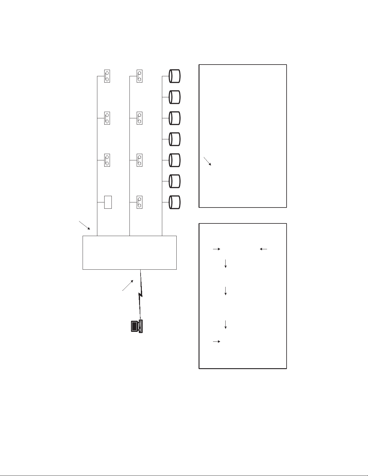
VFS113 Rack/Desktop Model User’s Guide
7
Disk
Disk1
Disk2
Disk3
Disk4
Disk5
Disk6
Disk7
VFS113
Disk
Robot
Tape1
Tape2
Tape3
Tape4
Tape5
Tape6
Device
6
Tape7
5
Tape 2 Tape 3
Tape 1
0123
Initiator ID
7
Channel 0
5689
Robot
7
Tape 5 Tape 6 Tape 7Tape 4
Channel 1
1
Disk
4
Disk
3
Disk
2
Disk
3456789
15
Channel 2
Disk
1
VFS113
0:0:0
0:1:0
0:2:0
0:3:0
1:5:0
1:6:0
1:8:0
1:9:0
2:3:0
Bus:Target:LUN
maps to
What the Host sees (sd.conf, st.conf)
012345678
FC LUN
1
1
1
0xE4
1
...
...
1
1
1
Loop ID
Loop ID
User configured (or
defaulted) @ VFS113
AL_PA
1
1
012
0xE8
0xEF
2:4:0
2:5:0
9
1011121314
1
1
soft
125
?
0x01
2:6:0
2:7:0
2:8:0
2:9:0
111
1
(starting at 0xEF)
Take first available
soft
15
1
A-2
Loop ID
Fibre Channel
Host Computer
0x0000EF
FC Address
Bus:Target ID
Host HBA and driver
Mapping depends on
0x0000E8
0:0
0:1
Figure A-1. VFS113 device address mapping
...
0x0000E4
...
0:2
?
0x000001
?
3:29
Page 73

Address and Device Mapping
Loop ID to AL_PA Mapping
During the Fibre Channel Arbitrated Loop (FC-AL) initialization process, a unique
Arbitrated Loop Physical Address (AL_PA) value is assigned to each port on the loop. Not
all of the 256 hex values are allowed as AL_PA values per FC-AL, so Loop IDs are used
to represent the 125 addresses that the router can use. You can assign a Loop ID to the
router. See Changing the Router’s Loop ID on page 3-8.
Table A-2 shows how a Loop ID value maps to an AL_PA. If you set the Loop ID to SOFT,
the router attempts to obtain an available Loop ID, in the following order: 0, 1, 2, etc.
Table A-2. Arbitrated loop physical addresses
Loop ID
(decimal)
0EF 19CA 38AA
1E8 20C9 39A9
2E4 21C7 40A7
3E2 22C6 41A6
4E1 23C5 42A5
5E0 24C3 43A3
6DC 25BC 449F
7DA 26BA 459E
8D9 27B9 469D
9 D6 28B6 479B
10 D5 29 B5 48 98
11 D4 30 B4 49 97
12 D3 31 B3 50 90
13 D2 32 B2 51 8F
AL_PA
(hex)
Loop ID
(decimal)
AL_PA
(hex)
Loop ID
(decimal)
AL_PA
(hex)
14 D1 33 B1 52 88
15 CE 34 AE 53 84
16 CD 35 AD 54 82
17 CC 36 AC 55 81
18 CB 37 AB 56 80
57 7C 80 55 103 31
58 7A 81 54 104 2E
59 79 82 53 105 2D
60 76 83 52 106 2C
61 75 84 51 107 2B
A-3
Page 74

VFS113 Rack/Desktop Model User’s Guide
Table A-2. Arbitrated loop physical addresses (Continued)
Loop ID
(decimal)
AL_PA
(hex)
Loop ID
(decimal)
AL_PA
(hex)
Loop ID
(decimal)
62 74 85 4E 108 2A
63 73 86 4D 109 29
64 72 87 4C 110 27
65 71 88 4B 111 26
66 6E 89 4A 112 25
67 6D 90 49 113 23
68 6C 91 47 114 1F
69 6B 92 46 115 1E
70 6A 93 45 116 1D
71 69 94 43 117 1B
72 67 95 3C 118 18
73 66 96 3A 119 17
74 65 97 39 120 10
75 63 98 36 121 0F
AL_PA
(hex)
❒
76 5C 99 35 122 08
77 5A 100 34 123 04
78 59 101 33 124 02
79 56 102 32 125 01
A-4
Page 75

D
LAN Configuration
Before you can access the Router Administrator software using the Ethernet port, you
must set up your router for TCP/IP. The following sections describe the router’s TCP/IP
setup.
A router that is part of a TCP/IP network requires three basic IP configuration elements: IP
address, subnet mask, and default gateway IP address. The router’s IP address must be
unique to the network in which the router resides. If the router is part of a publicly routed
network (that is, attached to the Internet), the address must be globally unique.
This appendix describes how to configure the TCP/IP settings for the first time starting
from the factory-set defaults.
Configuring the Router for TCP/IP
Before you can access the Router Administrator software, you must set the IP address and
subnet mask for the controller. The default IP address is 10.0.0.1. You can do this one of
four ways:
I Setting up your computer with an IP address that is compatible with the controller
default of 10.0.0.1, such as 10.0.0.42.
I Using address resolution protocol (ARP) to set the address. See Using Address
Resolution Protocol on page D-2.
I Using Dynamic Host Configuration Protocol (DHCP) to set the address. See Dynamic
Host Configuration Protocol Configuration on page D-3.
D-1
Page 76
VFS113 Rack/Desktop Model User’s Guide
Using Address Resolution Protocol
The ARP configuration method requires no IP address re-configuration of any computer
on the network. The ARP command is available in various forms and sometimes with
varying syntax in UNIX and Windows systems.
All routers are shipped with a unique Media Access Control (MAC) hardware address
(sometimes referred to as a physical address). Chaparral Network Storage MAC addresses
have the format “00-50-13-fx-xx-xx,” where “x-xx-xx” is unique to each router. The
router MAC address can be found on a label on the bottom of the router.
Note: TCP/IP protocol requires that all devices in a subnet have the same
octets, typically for the first three octets. For example, to use the default
Chaparral IP address of 10.0.0.1, other computers on the subnet must be
10.0.0.X, where X is the value between 2 and 254. ARP is useful because
you can temporarily assign a compatible IP address to the router.
To use ARP to resolve addresses in Windows:
1 You must first place the MAC address of the router being set up into your computer’s
ARP cache using the following command:
arp -s [IP address] 00:50:13:fx-xx-xx.
In this command, 00-50-13-fx-xx-xx is the router’s unique MAC address and IP
address is the IP address you or your LAN system administrator have chosen to use
as the IP address for the router.
This ARP command adds a static MAC-to-IP address binding to your computer. For
example, if you wanted to bind the router with the factory MAC address of 00-50-13f0-10-00 to the IP address 169.205.7.22, you should type arp –s 169.205.7.22 00-50-
13-f0-10-00.
Note: UNIX users see MAN Pages for ARP in your OS.
2 After entering the MAC address-to-IP address mapping into your computer’s ARP
cache, you can issue the command ping 169.205.7.22 to send a request to the router.
If the router addressed by the ping command does not respond, check the LAN
connection on the router.
3 If the ping command addressed to the router was successful, use Telnet to access the
router using the IP address you just configured (for example, 169.205.7.22).
4 Access the TCP/IP Configuration screen and enter the permanent IP address for the
router.
D-2
See Configuring the Additional LAN Settings on page D-3 and TCP/IP Configuration
Screen on page D-5.
Page 77

LAN Configuration
Dynamic Host Configuration Protocol Configuration
The Dynamic Host Configuration Protocol (DHCP) is a protocol designed to make IP
address assignment dynamic and automatic. When a router is configured in DHCP mode,
it generates a request for an IP address. The address is provided to the router and can be
used from that point forward.
In the dynamic address assignment mode, an IP address is leased to a DHCP-configured
router. You should ask your system administrator to configure your network so the router
can use DHCP and host name you have assigned to the router.
In the event you configure your router to DHCP and do not know which IP address was
assigned automatically, you can use ARP to discover which IP address was assigned to the
router by the DHCP server.
To discover which IP address was assigned to the router:
1 Follow the steps in the previous section for ARP to bind the router MAC address to a
temporary static IP address.
2 Use the command arp –g to display your computer’s the IP-to-MAC address table.
This table contains two entries corresponding to the router MAC address. One of the
entries contains the temporary static IP address you just bound to the router MAC
address, and the other entry is the DHCP-assigned IP address. You can use the DHCP
assigned address to access the router from any computer on the network.
Configuring the Additional LAN Settings
You can configure the following additional LAN settings:
I System information including the system name, Telnet password, FTP settings, and
the whether the Router Administration software or the Network Management System
Console displays by default when you use the Ethernet port.
I Simple Network Management Protocol (SNMP)
I Dynamic Host Configuration Protocol (DHCP)
I IP address and subnet mask
To configure additional LAN settings:
1 From the System Menu, select Configuration Menu and press Enter.
The Configuration Menu screen displays.
2 Select LAN Configuration and press Enter.
The LAN Configuration screen displays.
D-3
Page 78
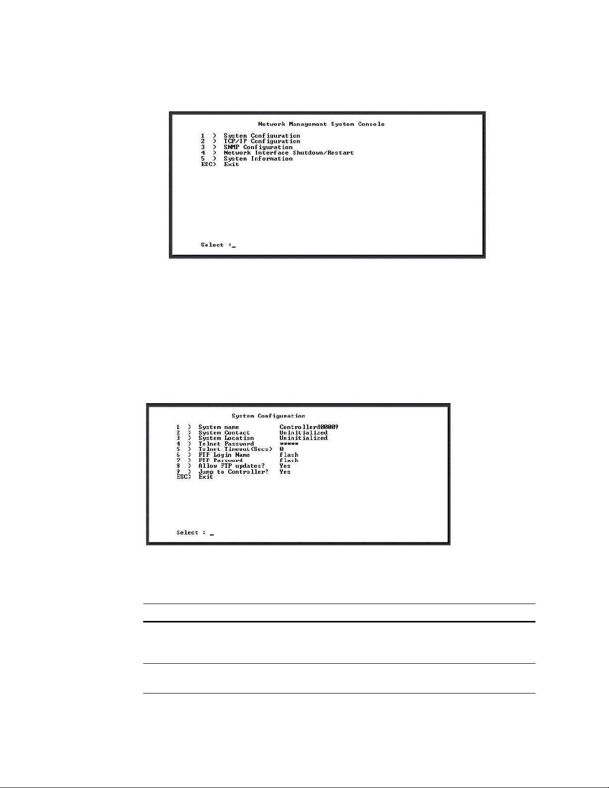
VFS113 Rack/Desktop Model User’s Guide
3 Select Ethernet Config and press Enter.
The Network Management System Console screen displays.
From here you can access the LAN settings. Each screen and its settings are
described briefly in the following sections. These settings are intended for use by
experienced network administrators. Refer to your operating system documentation
for more information about these settings.
System Configuration Screen
Option 1 from the Network Management System Console screen displays the System
Configuration screen.
Table D-1 describes the settings you can change here.
Table D-1. System Configuration screen settings
Option Setting Description
1 System name Name of the router as seen by other systems on the network.
You can enter up to 80 characters. Default is router fxxxxx
where xxxxx is the last 5 digits of the MAC address.
D-4
2 System Contact Name of a contact person responsible for the router. You can
enter up to 80 characters.
Page 79
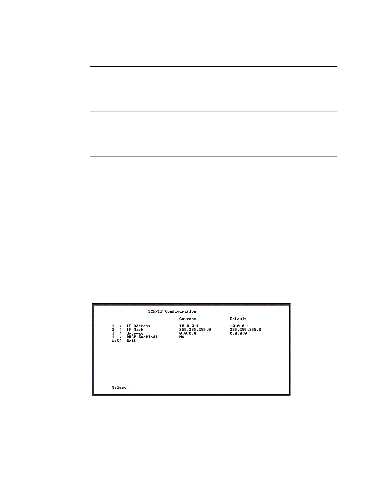
LAN Configuration
Table D-1. System Configuration screen settings (Continued)
Option Setting Description
3System
Location
4 Telnet Password Password for accessing the router using the Ethernet port and
5 Telnet Timeout Number of idle seconds before the Telnet session times out.
6 FTP Login
Name
7 FTP Password Password for FTP access to the router. You can enter up to 15
8 Allow FTP
Updates?
9Jump to
Controller?
ESC Exit Saves all changes and returns to the Network Management
Location of the router. You can enter up to 32 characters.
Telnet. You can enter up to 32 characters. Default is null (press
Enter).
Default is no timeout.
Login name for FTP access to the router. You can use FTP to
download firmware updates. You can enter up to 15 characters.
Default is flash.
characters. Default is flash.
Yes or No toggle. This permits firmware updates to the LAN
board using FTP.
Yes or No toggle. Yes means the Router Administrator
software displays after connecting to the controller using the
Ethernet port. No means the Network Management System
Console screen displays after connecting to the router using the
Ethernet port. The default is Yes.
System Console screen
TCP/IP Configuration Screen
Option 2 from the Network Management System Console screen displays the TCP/IP
Configuration screen.
D-5
Page 80
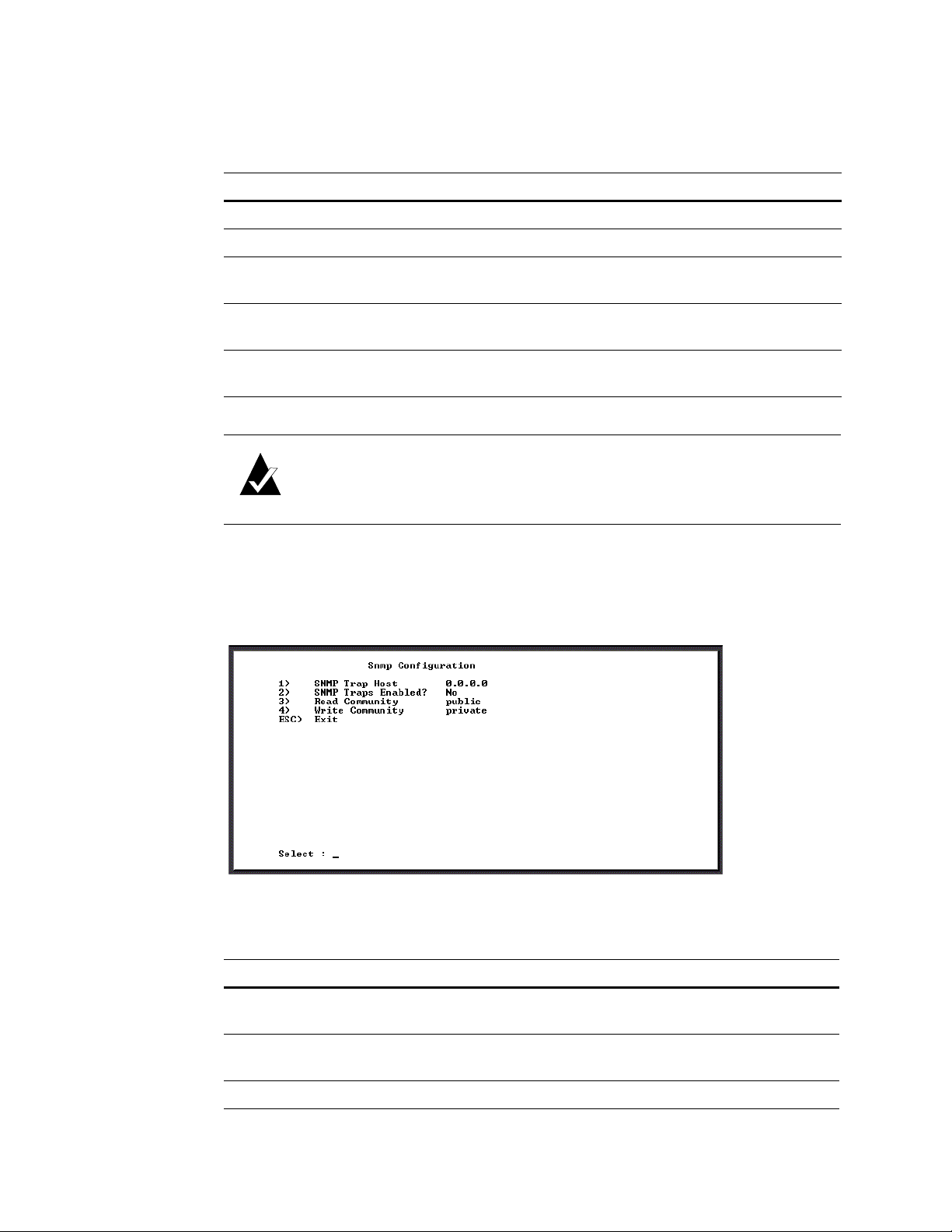
VFS113 Rack/Desktop Model User’s Guide
Table D-2 describes the settings you can change here.
Table D-2. System Configuration screen settings
Option Setting Description
1 IP Address Internet Protocol address of the router. Default is 10.0.0.1.
2 IP Mask Subnet mask. Default is 255.255.255.0.
3 Gateway Default is 0.0.0.0. See your network administrator for more
information.
4 DHCP Enabled? Yes or No toggle that enables or disables DHCP. Default is No
(disabled).
ESC Exit Saves all changes and returns to the Network Management
System Console screen
Note: Before choosing to enable DHCP, contact your network
administrator and make sure you have support for identifying IP hardware
and name server addresses.
SNMP Configuration Screen
Option 3 from the Network Management System Console screen displays the SNMP
Configuration screen.
Table D-3 describes the settings you can change here.
Table D-3. System Configuration screen settings
Option Setting Description
1 SNMP Trap Host Host computer’s IP address that is set up to receive SNMP
traps. Default is 0.0.0.0.
D-6
2SNMP Traps
Enabled?
3 Read Community SNMP read password. Default is Public.
On or off toggle to enable SNMP traps. Default is No
(disabled).
Page 81
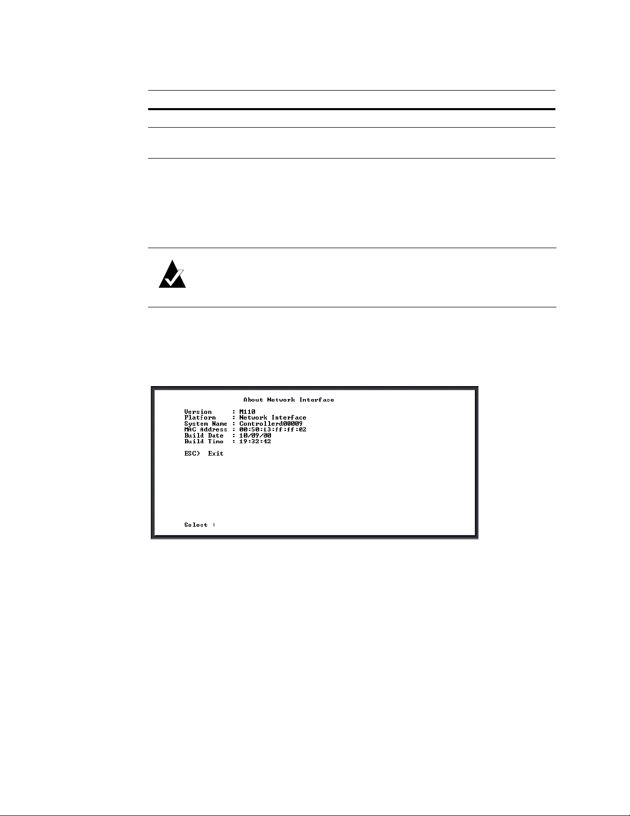
LAN Configuration
Table D-3. System Configuration screen settings
Option Setting Description
4 Write Community SNMP write password. Default is Private.
ESC Exit Saves all changes and returns to the Network Management
System Console screen
Restarting the LAN Board
Option 4 from the Network Management System Console screen restarts the LAN board.
A screen will display notifying you that your system is restarting.
Note: After rebooting the LAN connection you can return to the Password
screen by disconnecting and reconnecting the Telnet session.
System Information screen
Option 5 from the Network Management System Console screen displays the About
Network Interface screen displays.
You can view this read-only screen to get information about the system.
Returning to the Router Administrator Software
Press Esc from the Network Management System Console screen to return to the Router
Administrator software. Either the initial screen or the System menu displays. If the initial
screen displays, press Enter to display the System menu.
❒
You can now perform all of the functions described in this User’s Guide. All steps start
from the System Menu.
D-7
Page 82

VFS113 Rack/Desktop Model User’s Guide
D-8
Page 83

Standards
X3T11/Project 755D Fibre Channel Physical and Signaling Interface (FC-PH)
Specification - ANSI Standard X3.230-1994
X3T11/Project 1133D Fibre Channel Arbitrated Loop (FC-AL-2) Specifications, Rev 6.1 -
Draft ANSI Standard
X3T11/Project 959D Fibre Channel Switch Fabric (FC-SW) – Draft ANSI Standard
C
Reference Documents
X3T11/Project 1162DT Fibre Channel Private Loop SCSI direct attach (FC-PLDA) –
Draft ANSI Standard
X3T10/Project X3.269-199X Fibre Channel Protocol for SCSI, (FCP) Revision 12 -
ANSI Standard X3.269-199X.
X3T10/Project 1144D Fibre Channel Protocol for SCSI, Second Revision (FCP-2)
revision 00 – Draft ANSI Standard
X3T9.2/86-109 SCSI-2 Specification - ANSI Standard
X3T10/Project (various, see table below) SCSI-3 Working drafts for:
Document title Abbreviation Project Number
SCSI-3 Architecture Model SAM [T10/994-D]
SCSI-3 Block Commands SBC [T10/996-D]
SCSI-3 Stream Commands SSC [T10/997-D]
SCSI-3 Graphics Commands SGC [T10/998-D]
SCSI-3 Medium Changer Commands SMC [T10/999-D]
SCSI-3 Controller Commands SCC [T10/1047-D]
SCSI-3 Multimedia Commands MMC [T10/1048-D]
SCSI-3 Enclosure Services SES [T10/1212-D]
SCSI-3 Primary Commands SPC [T10/995-D]
SCSI-3 Parallel Interface SPI, SPI-2 [T10/855-D,
T1142D]
C-1
Page 84

VFS113 Rack/Desktop Model User’s Guide
Document title Abbreviation Project Number
SCSI-3 Fast-20 Parallel Interface [T10/1071-D]
SCSI-3 Interlocked Protocol SIP [T10/856-D]
SCSI-3 Serial Bus Protocol SBP [T10/992-D]
Note: Working draft standards documents in this section are available
from the following Web sites: http://www.t11.org/, http://www.t10.org/.
The exact status, revision level, and location may change as the drafts become standards
and are released.
Approved American National Standards and Technical Reports may be purchased from:
ANSI
11 West 42nd Street
13th Floor
New York, NY 10036
Books
Sales Dept: (212) 642-4900
or from:
Global Engineering Documents
15 Inverness Way East
Englewood, CO 80112-5704
Phone: (800) 854-7179; Outside USA and Canada: (303) 792-2181
Int’l Sales Fax: (303) 397-2740.
The following books give useful information about Fibre Channel:
Alan F. Brenner, Fibre Channel, McGraw-Hill, 1996
Tom Cl ark, Designing Storage Area Networks, Addison Wesley Longman, 1999
Jan Dedek, Fibre Channel – The Basics, ANCOT Corp., 1997
Robert Kembel, The Fibre Channel Consultant - Arbitrated Loop, Connectivity Solutions,
1998
Robert Kembel, The Fibre Channel Consultant – A Comprehensive Introduction,
Connectivity Solutions, 1998
❒
C-2
Page 85

Glossary
“A” controller—In Active-Active mode, one controller is designated as the “A”
controller and the other controller is designated as the “B” controller. Controller identity is
determined by enclosure hardware. The controller’s identity displays continuously at the
bottom of the Disk Array Administrator screens.
Address—An address is a data structure or logical convention used to identify a unique
entity, such as a particular process or network device.
Arbitrated loop physical address (AL_PA)—An AL_PA is a 1-byte value used in
an arbitrated loop topology. This value is used to identify L_Ports. The value then
becomes the last byte of the address identifier for each public L_Port on the loop.
Bus—See Channel.
Channel—A channel is a common physical path composed of wires or other media,
across which signals are sent from one part of a computer to another. A channel is a means
of transferring data between modules and adapters, or between an adapter and SCSI
devices. A channel topology network consists of a single cable trunk that connects one
workstation to the next in a daisy-chain configuration. All nodes share the same medium,
and only one node can broadcast messages at a time.
Fabric—Fabric refers to a switched topology, which is one of the three FC topologies.
Fabric elements, which are responsible for frame routing, interconnect various N_Ports or
NL_Ports. Depending on vendor support, fabric switches may be interconnected to
support up to 16 million N_Ports on a single network.
Failback—In Active-Active mode, failback is the act of returning ownership of
controller resources from a surviving controller to a previously failed (but now active)
controller. The resources include disk arrays, cache data, and host ID information.
Failover—In Active-Active mode, failover is the act of temporarily transferring
ownership of controller resources from a failed controller to a surviving controller. The
resources include disk arrays, cache data, and host ID information.
FC adapter—An FC adapter is a printed circuit assembly that translates data between the
FC host processor’s internal bus and FC link.
FC Arbitrated Loop (FC-AL)—FC-AL is one of three FC topologies in which ports
use arbitration to establish a point-to-point circuit. Arbitrated loops allow multiple ports to
be connected serially in a single loop. Up to 126 NL_Ports and 1 FL_Port can be
configured in a unidirectional loop. Ports arbitrate for access to the loop based on their
AL_PA. Ports with lower AL_PAs have higher priority than ports with higher AL_PAs.
FC device—A device that uses FC communications is referred to as an FC device.
FC port—An FC port is the opening at the back of a router that provides a fiber optic
connection between the FC adapter and FC host.
FC protocol for SCSI (FCP)—FCP defines an FC mapping layer (FC-4) that uses FCPH services to transmit SCSI command, data, and status information between a SCSI
G-1
Page 86

VFS113 Rack/Desktop Model User’s Guide
initiator and SCSI target. FCP enables transmission and receipt of SCSI commands, data,
and status across the FC using standard FC frame and sequence formats.
Fibre—Fibre is a generic FC term that refers to all transmission media types specified in
the FC Physical Layer standard (FC-PH), such as optical fiber, copper twisted pair, and
copper coaxial cable.
Fibre channel (FC)—FC is a bidirectional, point-to-point serial data channel, structured
for high-performance capability. In the physical sense, an FC is an interconnection of
multiple communication points, called N_Ports, by a switching network (fabric). FC
transports incoming data from devices by reading the buffer information, packaging it, and
sending the information across the fabric. Although FC is a generalized transport
mechanism that has no protocol of its own or native I/O command set, it can transport any
existing upper-level protocol such as SCSI and IP. FC offers high-speed data transfer rates
up to 1 Gbps. FC is most commonly used to connect clustered servers to storage systems.
ANSI has developed standards for FC.
Gigabit interface converter (GBIC)—A GBIC, also referred to as a Physical Link
Module, is a physical component that manages functions of the FC-0 layer. This layer
consists of the physical characteristics of the media and interface, including drivers,
transceivers, connectors, and cables. A GBIC attaches to an FC adapter and connects a
router to an FC host.
High voltage differential (HVD)—HVD is a differential SCSI scheme with
terminators that run on 5 volts.
Host bus adapter (HBA)—An HBA is the critical link between a host server or
workstation and a storage subsystem, integrating computing platforms, operating systems,
and I/O protocols to ensure proper interoperability and functionality. The bus adapter
provides direct storage connectivity from the system to data within the storage subsystem
and enables stable, high-speed transmission of information and files. HBAs manage the
controller-specific aspects of handling a storage driver interface device implemented as a
target driver, which supports mass storage peripheral devices such as disks and tapes. A
storage driver interface is used to implement SCSI and other storage device drivers. An
HBA connects to the storage subsystem to the host computer and uses either fiber or
copper media.
Initiator—An initiator is an FC or SCSI device that contains application clients that
originate service requests and task management functions for processing by a target FC or
SCSI device.
Initiator mode—Initiator mode is the configuration mode of a device in which an FC or
SCSI initiator requests operations to be performed by an FC or SCSI target device.
Kill—In Active-Active mode, one controller can kill the other controller by resetting it
and taking it offline.
Logical unit number or logical unit (LUN)—A LUN is a subdivision of a SCSI
target. For SCSI-3, each SCSI target supports up to 128 LUNs. An FC host using LUNs
can address multiple peripheral devices that may share a common controller.
G-2
Loop address—Loop address is an FC term that indicates the unique ID of a node in FC
loop topology. A loop address is sometimes referred to as a Loop ID.
Page 87

Glossary
Low voltage differential (LVD)—LVD is a method of powering SCSI cables that will
be formalized in the SCSI-3 specifications. LVD uses less power than the current
differential drive (HVD), is less expensive, and allows for higher speeds such as those of
Ultra2 SCSI. LVD requires 3.3 volts (versus 5 volts for HVD).
Management information base (MIB)—A MIB is a database of managed objects
accessed by network management protocols. An SNMP MIB is a set of parameters that an
SNMP management station can query or set in the SNMP agent of a network device (for
example, a router).
Mapping table—A mapping table is a table indexed by sequential LUN values. The
values indicate select bus:target:LUN devices. Mapping tables are used by some routers to
perform FC-to-SCSI operations by default.
Other controller—In Active-Active mode, the opposite controller from the one
currently being used (that is, not the local controller) is referred to as the other controller.
Ownership—In an active-active configuration, a single controller has ownership of the
following resources: arrays and dedicated spares. When a controller fails, the other
controller assumes temporary ownership of its resources.
Point to Point—A point-to-point connection is a communication link between two end
systems. Chaparral uses this term to refer to a link between the controller or router (Nport) and the F-port on a switch. The point-to-point topology is one of three FC topologies,
in which two ports are directly connected by a link; there are no fabric, loop, or switching
elements present.
Router—A router is a device that enables connectivity between SCSI devices and FC
networks. It routes each data command to the appropriate SCSI channel based on the
address it is intended for.
SCSI adapter —A SCSI adapter is a 16-bit fast/wide or 8-bit narrow, single-ended or
differential physical connection between a router and SCSI devices. Each SCSI adapter
supports up to 16 (fast/wide) or 8 (narrow) SCSI devices, including itself.
SCSI addressing—Each device supported by a SCSI adapter has its own unique SCSI
address, which dictates the device’s priority when arbitrating for access to the SCSI bus. A
SCSI address of 7 has the highest priority. For a fast/wide SCSI adapter that supports up to
16 devices, the next highest priority address is 6, then 5, 4, 3, 2, 1, 0, 15, 14, 13, 12, 11, 10,
9, and 8. A narrow SCSI adapter supports up to eight devices, including itself. The SCSI
address 7 has the highest priority, followed by 6, 5, 4, 3, 2, 1, and 0.
SCSI bus—A SCSI bus provides a means of transferring data between SCSI devices. A
SCSI bus is either an 8- or 16-bit bus that supports up to 8 or 16 devices, including itself.
The bus can consist of any mix of initiators and targets, with the requirement that at least
one initiator and one target must be present.
SCSI device—A SCSI device is a single unit on a SCSI bus that originates or services
SCSI commands. A SCSI device is identified by a unique SCSI address. SCSI devices can
act as initiators or targets.
SCSI port—A SCSI port is an opening at the back of a router that provides connection
between the SCSI adapter and SCSI bus.
G-3
Page 88

VFS113 Rack/Desktop Model User’s Guide
Simple Network Management Protocol (SNMP) —SNMP is the Internet standard
protocol, defined in STD 15, RFC 1157, developed to manage nodes on an Internet
Protocol (IP) network.
Small computer system interface (SCSI) —SCSI is an industry standard for
connecting peripheral devices and their controllers to an initiator. Storage devices are
daisy-chained together and connected to a host adapter. The host adapter provides a shared
bus that attached peripherals use to pass data to and from the host system. Examples of
devices attached to the adapter include disk drives, CD-ROM discs, optical disks, and tape
drives. In theory, any SCSI device can be plugged into any SCSI controller.
Speed—Speed is a status type in the FC Status Menu that shows the speed (1,063 Mbps)
of the FC adapter.
Storage area network (SAN)—SAN refers to the network behind servers that links
one or more servers to one or more storage systems. Each storage system could be RAID,
tape backup, tape library, CD-ROM library, or JBOD. SANs operate with both SCSI and
networking (IP) protocols. Servers and workstations use the FC network for shared access
to the same storage device or system. Legacy SCSI systems are interfaced using an FC-toSCSI bridge.
Targ et—A target is a device (peripheral) that responds to an operation requested by an
initiator (host system). Although peripherals are generally targets, a peripheral may be
required to act temporarily as an initiator for some commands (for example, SCSI
EXTENDED COPY command).
Terminator block/termination—A terminator block (or termination) refers to the
electrical connection at each end of a SCSI bus. The terminator block is composed of a set
of resistors, or possibly other components. The function of a terminator block is to provide
a pull-up for open collector drivers on the bus, and also impedance matching to prevent
signal reflections at the ends of the cable. SCSI buses require that a terminator be placed
on the 68-pin high-density SCSI connector on the last SCSI peripheral. Data errors may
occur in a SCSI bus that is not terminated.
Topology—A network topology refers to the physical layout of nodes on a network.
Topologies range from local network topologies to WAN topologies. FC topologies
include point-to-point, FC-AL, and fabric.
Trap—In the context of SNMP, a trap is an unsolicited message sent by an agent to a
management station. The purpose is to notify the management station of some unusual
event.
Unkill—In Active-Active mode, when a surviving controller removes the reset from the
other controller, it unkills it. The other controller will reboot and attempt to come online.
—
G-4
Page 89

Index
Numerics
0 light 12
1 light 12
2 light 12
A
About Network Interface screen 7
accessing the Router Administrator software 1
Address Mapping screen 20
Address Resolution Protocol, using to resolve IP
address 2
addresses
changing for devices 21
changing mapping mode of 20
displaying FC-to-SCSI address map 23
FC-to-SCSI mapping 1
alarm
disabling 16
enabling 16
temperature thresholds for 18
voltage thresholds for 18
Alarm screen 18
ARP, using to resolve IP address 2
AUTO setting 20
C
Change Address Map screen 22
changing
mapping mode 20
the router’s date 14
the router’s initiator ID 12
the router’s Loop ID 8
the router’s LUN 10
the router’s scan delay 15
the router’s SCSI ID 12
the router’s time 14
the screen display 6
Channel Configuration screen 12
Channel screen 12
Chaparral technical support 1
COM port, problems with 4
configuration information
changing 1
defined 28
displaying 27
Configuration Menu 7
configuration software, accessing 1
configuring the router 1
for TCP/IP 1
connecting
the router 7
to the Ethernet Port 10
to the FC port 8
to the RS-232 port 9
to the SCSI channels 7
conventions 2
customer support 1
D
date, changing for router 14
default settings, restoring 18
desktop, installing the router on 2
devices
changing addresses of 21
changing FC LUNs of 21
displaying a list of 23
displaying FC-to-SCSI address map 23
mapping of addresses 1
mapping of FC-to-SCSI addresses 1
SCSI channel problems 5
DHCP, using to resolve IP addresses 3
diagnostics
table of failures and solutions 2
disabling
the router’s termination 13
disabling, the router’s alarm 16
Disk Array Administrator
initial screen 4
System Menu 5
Display Address Map screen 22, 24
Display Devices screen 23
I-1
Page 90

VFS113 Rack/Desktop Model User’s Guide
displaying 23
configuration information 27
devices 23
events 24
hardware information 27
E
enabling, the router’s alarm 16
Ethernet card
upgrading firmware 33
Ethernet port
accessing the Disk Array Administrator software 3, 1
connecting to 10
Event Log Menu 25
Event Log screen 26
event log, displaying 24
events, displaying 24
Extended Copy 3
F
FC light 11
FC LUNs
changing for devices 21
changing mapping mode 20
displaying for router 30
FC port, connecting to 8
FC-to-SCSI address map 23
firmware
upgrading the Ethernet card 33
firmware, upgrading 31
FIXED setting 20
Flash Utility
restoring router configurations 3
Flash Utility screen 32
FS1310
mapping of addresses 1
FT light 11
fuse, replacing 6
G
H
Hardware Information screen 28, 8
hardware information, displaying 27
Host Configuration screen 7
HVD model 8
I
initial Disk Array Administrator screen 4
initial Router Administrator screen 2
initiator ID, changing for router 12
installing
example configurations of 4
in a rack 3
on a desktop or table 2
the router 1
IP addresses
resolving using ARP 2
resolving using DHCP 3
L
LAN, setting up to access controller software 3, 1
LED lights 11
LED status lights 11
lights 11
Loop ID
changing for router 8
settings for 8
SOFT setting 8
Loop ID screen 9
Loop ID to AL_PA mapping 3
LOOP topology setting 7
LUNs
changing for devices 21
changing for router 10
displaying for router 30
NONE setting 10
settings for 10
SOFT setting 10
LVD model 8
GBICs, compatible types of 8
I-2
M
MAC hardware address 2
map
Page 91

Index
displaying FC-to-SCSI address map 23
FC-to-SCSI addresses 1
Loop ID to AL_PA 3
mapping mode
AUTO setting 20
changing 20
FIXED setting 20
Mapping Mode screen 21
N
navigating in the Router Administrator software 5
network
setting up to access controller software 3, 1
Network Management System Console
SNMP Configuration screen 6
System Configuration screen 4
TCP/IP Configuration screen 5
Network Management System Console screen 6, 7
NONE setting 10
P
packing list 1
POINT-TO-POINT topology setting 7
POST, table of failures and solutions 2
powering down
devices 10
the router 10
powering up
devices 10
the router 10
Problem 5
problems
during bootup 1
router not responding 6
with COM port 4
with device SCSI channel 5
with terminal emulator 4
with terminal screen 4, 5
R
rack, installing the router in 3
rebooting
problems during 1
the router 19
replacing the fuse 6
resolving
IP addresses using ARP 2
IP addresses using DHCP 3
restarting the router 19
Restore Defaults screen 19
restoring router configurations 3
restoring the default settings 18
router
benefits 2
changing the date 14
changing the initiator ID 12
changing the Loop ID 8
changing the LUN 10
changing the scan delay 15
changing the SCSI ID 12
changing the time 14
configurations restoring 3
configuring 1
configuring TCP/IP 1
connecting to the Ethernet port 10
connecting to the FC port 8
connecting to the RS-232 port 9
connecting to the SCSI channels 7
default settings 12
disabling the alarm 16
disabling the termination 13
displaying configuration information 27
displaying devices connected to 23
displaying events 24
displaying hardware information 27
displaying its FC LUN 30
enabling the alarm 16
features 2
installing 1
installing in a rack 3
installing on a desktop or table 2
making the data connections 7
mapping of addresses 1
rebooting 19
restoring default settings 18
selecting the topology 7
specifications 4
unpacking 1
upgrading firmware 31
Router Administrator 7
I-3
Page 92

VFS113 Rack/Desktop Model User’s Guide
accessing 1
Address Mapping screen 20
Alarm screen 18
Change Address Map screen 22
Channel Configuration screen 12
Channel screen 12
Configuration Menu 7
Display Address Map screen 22, 24
Display Devices screen 23
Even Log 26
Even Log Menu 25
Hardware Information screen 28, 8
Host Configuration 7
initial screen 2
Loop ID 9
Loop ID screen 11
Mapping Mode screen 21
navigating in 5
Restore Defaults screen 19
Router LUN 11
Scan Configuration screen 16
Set Date screen 14
Set Date/Time screen 14
Set Time screen 15
System Menu 2
Termination screen 13
Utilities Menu 28, 8
router LUN 10
Router LUN screen 11
RS-232 port
connecting to 9
problems with 4
settings for 9
S
Scan Configuration screen 16
scan delay, changing for router 15
screens
Address Mapping 20
Alarm 18
Change Address Map 22
Channel 12
Channel Configuration 12
Configuration Menu 7
Display Address Map 22, 24
Display Devices 23
Event Log 26
Event Log Menu 25
Flash Utility 32
Hardware Information 28, 8
Host Configuration 7
initial Router Administrator 2
Loop ID 9
Mapping Mode 21
navigating in 5
Restore Defaults 19
Router LUN 11
Scan Configuration 16
Set Date 14
Set Date/Time 14
Set Time 15
System Menu 2
Utilities Menu 28, 8
SCSI channels
changing mapping mode 20
connecting to 7
HVD 8
LVD 8
problems with 5
single-ended narrow 8
Ultra2 wide 8
SCSI devices
changing addresses of 21
changing FC LUNs of 21
displaying 23
SCSI ID, changing for router 12
self-test, table of failures and solutions 2
serial port 9
connecting to 9
problems with 4
serverless backup 3
Set Date screen 14
Set Date/Time screen 14
Set Time screen 15
setting up the router 1
settings
for the RS-232 port 9
settings for 9, 10
shutting down the router 19
SNMP Configuration screen 6
SOFT setting 8, 10
I-4
Page 93

Index
software
accessing to configure the router 1
navigating in 5
specifications 4
ST light 11
status lights 11
support 1
System Configuration screen 4
System Menu 2, 5
T
table, installing the router on 2
TCP/IP
configuring the router 1
setting up to access controller software 3, 1
using ARP to set up 2
using DHCP to set up 3
TCP/IP Configuration screen 5
technical support 1
temperature, alarm thresholds for 18
terminal
screen problems 5
terminal emulator software 1
terminal emulator, problems with 4
terminal screen problems 4
termination
disabling 13
Termination screen 13
time, changing for router 14
topology
LOOP setting 7
POINT-TO-POINT setting 7
selecting 7
troubleshooting
COM port 4
device SCSI channel problems 5
problems during bootup 1
router not responding 6
terminal emulator 4
typographic conventions 2
V
VFS113
benefits 2
changing the date 14
changing the initiator ID 12
changing the Loop ID 8
changing the LUN 10
changing the scan delay 15
changing the SCSI ID 12
changing the time 14
configuring 1
connecting to the FC port 8
connecting to the RS-232 port 9
connecting to the SCSI channels 7
disabling the alarm 16
displaying configuration information 27
displaying devices connected to 23
displaying events 24
displaying hardware information 27
displaying its FC LUN 30
enabling the alarm 16
features 2
installing 1
installing in a rack 3
installing on a desktop or table 2
making the data connections 7
rebooting 19
restoring default settings 18
selecting the topology 7
specifications 4
unpacking 1
upgrading firmware 31
voltage, alarm thresholds for 18
U
unpacking the router 1
upgrading firmware 31
Utilities Menu 28, 8
I-5
Page 94

VFS113 Rack/Desktop Model User’s Guide
I-6
Page 95

Page 96

Chaparral Network Storage, Inc.
7420 E. Dry Creek Parkway
Longmont, CO 80503
© 2000, 2001 Chaparral Network Storage, Inc.
All rights reserved. Chaparral and Chaparral logo are
trademarks of Chaparral Network Storage, Inc.
Printed in the U.S.
10/01
Document Number: 07-0015-006-B
 Loading...