

Page 1

G- and K-Series
External RAID Board Controller
G5312/G7313
K5312/K7313
User’s Guide
Page 2

Page 3

Copyright
©1999, 2000 Chaparral Network Storage, Inc.
Document Number: 07-0033-003
This document covers G5312, G7313, K5312, and K7313.
All rights reserved. No part of this publication may be reproduced without the prior written consent of:
Chaparral Network Storage, Inc.
7420 E. Dry Creek Parkway
Longmont, Colorado 80503
http://www.chaparralnet.com
Trademarks
Chaparral Network Storage, Inc. and the Chaparral logo are trademarks of Chaparral Network Storage, Inc.
AHA and AIC are trademarks of Adaptec, Inc.
Windows is a registered trademark and Windows NT is a trademark of Microsoft Corporation in the U.S.
and other countries, used under license.
All other trademarks are owned by their respective owners.
Changes
The material in this document is subject to change without notice. While reasonable efforts have been made
to ensure the accuracy of this document, Chaparral Network Storage, Inc. assumes no liability resulting
from errors or omissions in this publication, or from the use of the information contained herein.
If you would like to provide comments or suggestions on the quality and/or accuracy of this manual, please
contact Chaparral at http://www.chaparralnet.com/manuals.
Chaparral reserves the right to make changes in the product design without reservation and without
notification to its users. Comments and suggestions can be sent to the address listed above.
Technical Support
If after reviewing this user ’s guide, you still have questions about installing or using your Chaparral
product, please contact us at (303) 684-3200 or by e-mail at [email protected]
Federal Communications Commission Radio Frequency Interference Statement
WARNING: Changes or modifications to this unit not expressly approved by the party responsible for
compliance could void the user’s authority to operate the equipment.
This equipment has been tested and found to comply with the limits for a Class A digital device, pursuant
to Part 15 of the FCC rules. These limits are designed to provide reasonable protection against harmful
interference in a residential installation. This equipment generates uses, and can radiate radio frequency
energy, and if not installed and used in accordance with the instruction manual, may cause harmful
interference to radio communications. However, there is no guarantee that interference will not occur in a
particular installation. However, if this equipment does cause interference to radio or television equipment
reception, which can be determined by turning the equipment off and on, the user is encouraged to try to
correct the interference by one or more of the following measures:
Reorient or relocate the receiving antenna.
!
Increase the separation between equipment and receiver.
!
i
Page 4

Connect the equipment to an outlet on a circuit different from that to which the receiver is connected.
!
Consult the dealer or an experienced radio/television technician for help.
!
Use a shielded and properly grounded I/O cable and power cable to ensure compliance of this unit to
!
the specified limits of the rules.
This device complies with part 15 of the FCC rules. Operation is subject to the following two conditions:
(1) this device may not cause harmful interference and (2) this device must accept any interference
received, including interference that may cause undesired operation.
Canadian Compliance Statement
This Class A digital apparatus meets all requirements of the Canadian Interference-Causing Equipment
Regulations.
Cet appareil numérique de la classe A respecte toutes les exigences du Règlement sur le matérial brouilleur
du Canada
ii
Page 5

1 Introduction
About This Guide 1-1
Conventions 1-2
Product Features 1-2
Motherboard CPU Subsystem (G-Series) 1-2
Motherboard Ultra2 SCSI Channels (G-Series) 1-2
Motherboard Disk Cache (G-Series) 1-3
Battery Interface (G-Series) 1-3
Hardware Configuration and Management Support
(G-Series) 1-3
Onboard Connectors (G-Series) 1-4
Daughterboard (G-Series) 1-4
Motherboard CPU Subsystem (K-Series) 1-4
Motherboard Ultra2 SCSI Channels (K-Series) 1-4
Motherboard Disk Cache (K-Series) 1-5
Integrated Battery Backup and Interface (K-Series) 1-5
Hardware Configuration and Management Support
(K-Series) 1-6
Onboard Connectors (K-Series) 1-6
Fibre Channel Connection (K-Series) 1-6
Fibre Channel Features 1-6
Specifications 1-7
Physical (G-Series) 1-7
Electrical (G-Series) 1-7
Environmental (G-Series) 1-8
Battery (G-Series) 1-9
Physical (K-Series) 1-10
Electrical (K-Series) 1-10
Contents
iii
Page 6

G- and K-Series User’s Guide
Environmental (K-Series) 1-11
Battery (K-Series) 1-12
Reference Documents 1-13
External Documents 1-13
Chaparral Documents 1-13
2 Hardware Installation
Connecting the Controller 2-1
Connecting to the SCSI Port 2-1
Connecting to the Fibre Channel Port 2-1
Connecting to the RS-232 Port 2-2
3 Accessing the Disk Array Administrator
Software
Accessing the Disk Array Administrator Using the RS-232 Serial Port 3-1
Navigating the Disk Array Administrator Software 3-3
Changing the Screen Display 3-4
Disk Array Administrator Menu Tree 3-4
4 Creating and Managing Arrays
Creating Arrays 4-1
Managing Arrays 4-8
Viewing Array Status 4-8
Stopping the Array Initialization Process 4-14
Verifying an Array 4-15
Reconstructing an Array 4-17
Expanding Array Capacity 4-18
Changing the Array LUN 4-21
Changing the Array Name 4-22
Trusting an Array 4-22
Deleting an Array 4-24
iv
Page 7

Contents
5 Monitoring System Status
Displaying the Event Log 5-1
Viewing the Most Recent Event 5-2
Viewing One Event at a Time 5-2
Viewing a Whole Screen of Events 5-4
Capturing the Event Log File 5-4
Displaying Hardware and Configuration Information 5-5
Displaying Overall Statistics 5-11
Resetting Overall Statistics 5-14
6 Managing Spares
Managing Dedicated Spares 6-1
Adding a Dedicated Spare 6-2
Deleting a Dedicated Spare 6-3
Enabling Dynamic Spares 6-3
Managing the Spare Pool 6-5
Adding a Spare to the Spare Pool 6-5
Deleting a Spare from the Spare Pool 6-6
Displaying the Spare Pool 6-7
7 Configuring the Controller
Rebooting the Controller 7-1
Changing the Date and Time 7-2
Changing the Controller’s LUN and SCSI Target ID or Fibre Channel Loop
ID 7-4
Understanding LUNs 7-4
Changing the Controller’s Target ID and LUN 7-6
Configuring the SCSI Channels 7-9
Working with LUN Zoning 7-11
Viewing Known WWNs 7-12
Creating Names (Aliases) for Server WWNs 7-14
v
Page 8

G- and K-Series User’s Guide
Configuring LUN Zoning 7-15
Changing the Sample Rate 7-17
Changing the Alarm Mute Setting 7-18
Locking the Cache Setting 7-20
Enabling and Disabling the Battery 7-21
Changing the Utility Priority 7-22
Rescanning All Channels 7-23
Pausing I/O 7-24
Restoring Default Settings 7-25
Upgrading Firmware 7-26
Upgrading the Controller’s Firmware 7-26
8 Managing Disk Drives and Enclosures
Managing Disk Drives 8-1
Displaying Drive Information 8-2
Clearing Metadata from a Drive 8-4
Enabling and Disabling Write-back Cache 8-5
Displaying Disk Cache Status 8-7
Enabling and Disabling SMART Changes 8-8
Blinking a Drive LED 8-9
Taking Down a Drive 8-10
Testing a Drive 8-11
Managing SAF-TE Enclosures 8-11
Changing the SEP LUN 8-12
Changing the Additional SEP Settings 8-14
9 Troubleshooting
Chaparral Technical Support 9-1
Terminal Emulator and COM Port Problems 9-1
Array Problems 9-2
Host SCSI Channel Problems 9-3
vi
Page 9

Contents
Device SCSI Channel Problems 9-4
Problems During Bootup 9-4
Controller Problems 9-5
Warning And Error Events 9-6
Warnings 9-7
Errors 9-8
Using the Loader Diagnostics Menu 9-9
Using the Loader Utility Menu 9-9
Understanding SCSI Errors 9-9
Disk Errors 9-9
Disk Channel Errors 9-11
Voltage and Temperature Errors and Warnings 9-13
A Array Basics
Array Types A-1
RAID 0 (Striped Disks) A-1
RAID 1, RAID 1/O (Mirrored Disks) A-2
RAID 3 A-2
RAID 4 A-3
RAID 5 A-3
RAID 50 A-3
Volume Sets A-4
Comparing RAID Levels A-4
Mixing Disks from Different Manufacturers or with Different
Capacities A-6
Mixing Disks on Different RAID Controller Channels A-6
B Glossary
vii
Page 10

G- and K-Series User’s Guide
viii
Page 11

1
Introduction
This
User’s Guide
External RAID Controllers, which are designed to be installed in a RAID enclosure
and used with a host system to provide a powerful disk subsystem.
The G5312 and K5312 RAID controllers are fault-tolerant SCSI-to-SCSI RAID
controllers that bridge the SCSI interface between the host system and the SCSI hard
drive peripherals. They support low voltage differential (LVD) Ultra2 or single-ended
Ultra SCSI buses. The G5312 and K5312 have one Ultra2 SCSI host channel and two
Ultra2 SCSI disk channels. Each disk channel is a separate SCSI bus.
The G7313 and K7313 offer all of the features of the G5312 and K5312 except that
they support Fibre Channel (FC) connectivity, single loop. They each have one FC
host and three Ultra2 SCSI disk channels.
Administrative software is embedded in firmware; thus, the G- and K-Series requires
no specific software drivers for the host operating system.
explains how to install and use the Chaparral G- and K-Series
About This Guide
This User’s Guide describes how to install and configure your Chaparral RAID
controller. It assumes that you are familiar with the basic functions of your computer
system. It also assumes that you are familiar with SCSI and Fibre Channel
configurations and basic network administration terminology.
1-1
Page 12
G- and K-Series User’s Guide
Conventions
This
controller.
uses several typographical conventions to help explain how to use the
Guide
Convention Description
Bold Wor d s in bold indicate items to select such as menu items
or command buttons.
CTRL-R Keys you press simultaneously. In this example, hold
down the Ctrl key and press the r key.
Notes give you important information that may affect how
you decide to set up your system.
Cautions warn you about actions that may permanently
!
delete data or cause damage to your system.
Product Features
The following sections describe the features of the G- and K-Series RAID controllers.
Motherboard CPU Subsystem (G-Series)
Am5x86-133 MHz processor with internal 16 KB L1 unified code and data
!
cache
8-MB zero-wait state, burst mode, extended-data out (EDO) DRAM memory
!
(independent of disk cache)
1-MB nonvolatile sectored Flash event/code/configuration store memory
!
Motherboard Ultra2 SCSI Channels (G-Series)
Onboard Adaptec AIC™-789x PCI-Ultra2 SCSI interface controller ASICs
!
All SCSI channels support Wide Ultra2 SCSI (80 MB/sec)
!
Each SCSI channel can independently auto-sense LVD and single-ended modes
!
and negotiate Narrow or Wide SCSI
1-2
Page 13

Introduction
Supports full backward compatibility for asynchronous, fast, Ultra 1, and
!
Ultra2 SCSI (80 MB/sec)
SCSI terminators and termination power sources must reside in the enclosure
!
subsystem
Note:
There is no support for high-voltage differential (HVD) SCSI
(RS-485 SCSI-3 compliant).
Motherboard Disk Cache (G-Series)
Adaptec AIC-2100 dual-port PCI disk cache ECC memory controller
!
PCI-to-PCI Bridge providing full CPU and PCI bus concurrency
!
Disk cache size modularity using standard SDRAM 168-pin ECC DIMM
!
(16 MB to 128 MB)
Battery backup switching regulator and control interface for disk cache memory
!
Battery Interface (G-Series)
Battery charger and battery control interface
!
Integrated software-controlled battery charger, diagnostics, and periodic battery
!
monitoring
Battery pack connection to the motherboard or to the backplane interface
!
Nickel Metal Hydride (NiMH) battery pack delivery of a minimum of 72 hours
!
continuous backup to disk cache memory
Hardware Configuration and Management Support (G-Series)
Dual RS-232 serial ports
!
Analog-to-digital converter for power, temperature, and enclosure monitoring
!
Onboard standard PC-type lithium disk battery for continuous Real-Time Clock
!
(RTC) power when the unit is shut down
Dedicated channel activity LEDs, status LEDs, and alarm I/O to backplane
!
connector interface
1-3
Page 14

G- and K-Series User’s Guide
General purpose I/O for enclosure-specific functions to backplane connector
!
interface
SAF-TE support for enclosure management.
!
Onboard Connectors (G-Series)
2-pin fan connector (fused 12.0 V)
!
3-pin battery pack connector
!
6-pin status/fault/backup LED connector
!
Daughterboard (G-Series)
The G7313 incorporates a FC daughterboard for single loop Fibre Channel
connectivity.
Motherboard CPU Subsystem (K-Series)
The K-Series motherboard that is installed in an enclosure includes the following
features:
IDT C6/C6+ Winchip, 200 MHz processor with internal 64-KB L1 cache and a
!
66 MHz/64-bit external bus
8-MB zero-wait state DRAM memory (independent of disk cache)
!
2-MB nonvolatile sectored Flash event/code/configuration store memory
!
Motherboard Ultra2 SCSI Channels (K-Series)
Three onboard Ultra2 SCSI (also known as LVD) channels
!
Adaptec AIC-7890 and Adaptec AIC-7896 PCI-LVDS interface controller
!
ASICs
Ultra2 SCSI channel 0 can operate as an independent target or initiator
!
(software dependent)
All SCSI channels support Wide Ultra2 SCSI (80 MB/sec)
!
Each SCSI channel can independently auto-sense LVD and single-ended modes
!
and negotiate Narrow or Wide SCSI
1-4
Page 15

Introduction
Supports full backward compatibility for asynchronous, fast, Ultra 1
!
(40 MB/sec), and Ultra2 SCSI (80 MB/sec)
Onboard Ultra2 SCSI terminators supporting auto-detection and auto-
!
configuration for LVD/SE
Onboard termination power source circuit breakers
!
Note:
There is no support for high-voltage differential (HVD) SCSI (RS-
485 SCSI-3 compliant).
Motherboard Disk Cache (K-Series)
Adaptec AIC-2100 dual-port PCI disk cache ECC memory controller
!
PCI-to-PCI Bridge providing full CPU and PCI bus concurrency
!
Disk cache size modularity using standard SDRAM 168-pin ECC DIMM
!
(16 MB to 128 MB)
Battery backup switching regulator and control interface for controller cache
!
memory
Onboard battery charger and intelligent control/monitoring interface
!
Integrated Battery Backup and Interface (K-Series)
Battery charger and battery control interface
!
Integrated software controlled battery charger, diagnostics, and periodic battery
!
monitoring
Nickel Metal Hydride (NiMH) battery pack delivery of greater than 72 hours
!
continuous backup to controller cache memory
Software-controlled battery charger and diagnostics
!
1-5
Page 16

G- and K-Series User’s Guide
Hardware Configuration and Management Support (K-Series)
RS-232 serial port for configuration and troubleshooting
!
Analog-to-digital converter for power, temperature, and enclosure monitoring
!
Onboard standard PC-type lithium battery for continuous Real-Time Clock
!
(RTC) power when the unit is shut down
Onboard Connectors (K-Series)
Qty = two 2-pin fan connector (fused 12.0 V)
!
3-pin battery pack connector
!
Front panel 26-pin connector
!
Fibre Channel Connection (K-Series)
The K7313 features a Fibre Channel connection for single loop Fibre Channel
connectivity.
Fibre Channel Features
JNI FC interface controller
!
64 KB x 18 parity-protected synchronous SRAM for queuing up to 500
!
command blocks
VSC7125 full-speed 10-bit transceiver, SERDES, for FC-0 interface
!
93C56 serial EEPROM, 2 Kbit in 128 x 16 organization, for storing system
!
configuration parameters
MIA detection circuit for optical module operation support
!
LT1117, 5.0 V to 3.3 V stepdown linear voltage regulator for local 3.3 V supply
!
106.25 MHz clock generator for full-speed FC operation
!
1-6
Page 17

Introduction
Specifications
The following sections describe the physical, electrical, environmental, and battery
specifications of the G- and K-Series.
Physical (G-Series)
Table 1-1 shows the physical specifications of the motherboard and daughterboard:
Table 1-1. Physical Specifications
Item Specifications
Motherboard Form factor: 4.25 x 9.0 inch PCB outline
0.77 inch max Z-axis height without daughterboard
1.02 inch max Z-axis height single daughterboard
376-pin backplane connector receptacle
Daughterboard Form factor: 4.0 x 2.19 inch max PCB board, 0.54 inch
typical Z-axis height above top surface of motherboard PCB
100-pin surface mount connectors with 0.8-mm pin pitch,
7-mm connector stack height
Electrical (G-Series)
Table 1-2 shows the electrical specifications of the controllers:
Table 1-2. Electrical Specifications
Item Specifications
VCC +5.0 Vdc G5312/G7313:
3.0A typical Ultra2 SCSI host
4.0A max Ultra2 SCSI host
4.0A typical FC host
5.0A max FC host
A/D Monitoring -3.5% to +6.5% Normal operation
4.825 Vdc to 5.325 Vdc
>-6.5% to <+10.0% Degraded mode
(warning alert)
>4.67 Vdc to <5.5 Vdc
1-7
Page 18

G- and K-Series User’s Guide
Table 1-2. Electrical Specifications (Continued)
Item Specifications
<-6.5%, >+10.0 Controller shutdown
(failure)
<4.67 Vdc, 5.5 Vdc
+12V +12 Vdc 0.6A max battery charging
0.1 A typical normal operation
0.2 A max normal operation
A/D Monitoring ±10.0% normal operation
(10.8 Vdc to 13.2 Vdc)
>±10% Degraded mode (warning alert)
(9.6 Vdc to 10.8 Vdc)
(13.2 Vdc to 14.4 Vdc)
>±20% Controller shutdown (failure)
<9.6 Vdc and >14.4 Vdc
Environmental (G-Series)
Table 1-3 shows the environmental specifications of the controllers:
Table 1-3. Environmental Specifications
Item Specifications
Reliability MTBF (Mean Time Between Failure): 200,000 power-
on hours
MTTR (Mean Time To Repair): 20 minutes
Temperature Internal ambient operating:
o
C to 50oC maximum with specified air flow for
5
G5312
o
C to 45oC maximum with specified air flow for
5
G7313
o
Normal operating: 5
o
5
C to 45oC for FC host
Degraded mode operating: 0
C to 50oC for SCSI host,
o
C to 5oC and 50oC to 55oC
for SCSI host,
o
C to 5oC and 45oC to 55oC for FC host
0
Non-operating: -40
o
C to +100oC
1-8
Page 19

Introduction
Table 1-3. Environmental Specifications (Continued)
Item Specifications
Humidity Operating: 10% to 85% non-condensing
Non-operating: 5% to 90% non-condensing
1
Air flow 10.0 cubic feet/minute (CFM
longitudinal axis of controller at maximum temperature
Vibration 5 Hz @ 2.0 x 10⁻⁷ PSD, 17-500 Hz @ 2.2 x 10
(PSD = power spectral density g
9711-002
Shock Vertical: 30.0 g @ 3.0 msec pulse width
Horizontal: 15.0 g @ 3.0 msec pulse width per IBM C-S
1-9711-007
1
Linear flow along controller Y (long) axis
) minimum along
2
/Hz) per IBM C-S 1-
-5
PSD
Battery (G-Series)
Table 1-4 shows the specifications of the G5312/G7313 battery available from
Chaparral:
Table 1-4. Battery Specifications
Item Specifications
Charge time 4 hours maximum
o
Operating range 5
Storage
temperature
Storage humidity 65% ± 20%
C to +40oC = 3 year life; > 40oC = 1 year life
o
C to +40oC
-20
A fully charged battery can provide a minimum of 72 hours backup time using all
ranges of DIMM sizes. Replace batteries only with the same type as provided by the
manufacturer. Dispose of batteries according to manufacturer’s instructions.
If you must store the battery for a long time, you should take certain precautions to
ensure the battery has sufficient charge when it is returned to service. The
recommended storage temperature is between +5°C to +25°C. Avoid temperature
extremes exceeding -20°C or +40°C for any extended period of time. Exposure to
extreme temperatures causes the battery to discharge at a faster rate and can take
longer to take a full charge when it is returned to service. A new battery or fully
discharged battery can take from four to eight hours or more to fully charge.
1-9
Page 20

G- and K-Series User’s Guide
Physical (K-Series)
Table 1-5 shows the physical specifications of the motherboard and daughterboard.
Table 1-5. Physical Specifications
Item Specifications
Motherboard Form factor: 4.95 x 7.34 inch motherboard PCB, 1.25 inch max Z-axis
height
AMP Z-Pack backplane mating receptacle, 235-pin connector with
combined LVD, FC, RS-232 serial port, I
(GPIO), and power
Daughterboard Form factor: 4.0 x 2.19 inch max PCB board, 0.54 inch typical Z-axis
height above top surface of motherboard PCB.
100-pin surface mount connectors with 0.8-mm pin pitch, 7-mm
connector stack height
2
C, general purpose I/O
Electrical (K-Series)
Table 1-6 shows the electrical specifications of the controllers.
Table 1-6. Electrical Specifications
Item Specifications
VCC +5.0 Vdc 3.0 A max operating current (K5312, LVDS host)
4.0 A max operating current (K7313, Fibre Channel
host)
A/D Monitoring -3.5%, +6.5% normal operation
4.825 Vdc to 5.325 Vdc
-5.0%, +10% degraded mode (warning alert)
4.75 Vdc to 5.5 Vdc
<-5.0%, >+10.0% controller shutdown (failure)
+12V +12.0 Vdc 1.4 A max operating current (no battery or battery
charged)
1.8 A max operating current (battery charging)
1-10
Page 21

Introduction
Table 1-6. Electrical Specifications
Item Specifications
A/D Monitoring ± 8.0% normal operation
11.04 Vdc to 12.96 Vdc
± 10.0% degraded mode (warning alert)
(10.8 Vdc) (13.2 Vdc)
>± 10.0% controller shutdown (failure)
14.4 Vdc
Battery 0.4 A max charging current
0.04 A typical trickle charge current (normal
operation)
A/D Monitoring Internal thermocouple in battery pack monitored
Warning issued if pack exceeds temperature range
o
C to 45oC)
(5
Write back cache remains enabled during battery
pack thermal warning
Environmental (K-Series)
Table 1-7 shows the environmental specifications of the controllers.
Table 1-7. Environmental Specifications
Item Specifications
Reliability K5312 Main Board: MTBF = 200,000 hours
K7313 Main and Fibre Boards: MTBF = 140,000 hours
CPU Fan = 37,523, MTTF = 4.3 years
Battery = 26,300, MTTF - 3.0 years
Note: Battery life is probably higher based on duty cycle, battery
stress is primarily during re-charge activity if battery backup is
activated.
o
Tem per atu re 5
C to 45oC normal operating range with unobstructed airflow
o
C to 5oC and 45oC to 50oC degraded mode operating range
0
o
C to +100oC non-operating/storage (without battery pack)
-40
o
5
C to 25oC non-operating/storage (with battery pack)
1-11
Page 22
G- and K-Series User’s Guide
Table 1-7. Environmental Specifications
Item Specifications
Humidity 10% to 85% non-condensing operating (without battery pack)
60% to 70% non-condensing operating/non-operating (with battery
pack)
5% to 90% non-condensing non-operating (without battery pack)
Air flow Internally cooled, unobstructed
-7
Vibration 5 Hz @ 2.0 x 10
spectral density g
Shock Vertical: 30.0 g @ 3.0 msec pulse width
Horizontal: 15.0 g @ 3.0 msec pulse width per IBM C-S 1-9711-007
PSD, 17-500 Hz @ 2.2 x 10
2
/Hz) per IBM C-S 1-9711-002
-5
PSD (PSD = power
Battery (K-Series)
Table 1-8 shows the specifications of the battery available from Chaparral.
Table 1-8. Battery Specifications
Item Specifications
Charge time 4 hours maximum
o
Operating range 5
Storage
temperature
Storage humidity 65% ± 5%
C to +40oC = 3 year life; > 40oC = 1 year life
o
C to 25oC
5
Note:
Outside these limits the battery life will be diminished.
If you must store the battery for a long time, you should take certain precautions to
ensure the battery has sufficient charge when you return it to service. The
recommended storage temperature is between +5
extremes exceeding -20
o
C or +40oC for any extended period of time. Exposure to
o
C to +25oC. Avoid temperature
extreme temperatures causes the battery to discharge at a faster rate and can take
longer to take a full charge when it is returned to service. A new battery or fully
discharged battery can take from four to eight hours or more to fully charge.
1-12
Page 23

Introduction
Reference Documents
External Documents
Adaptec’s AIC-7890/91 and AIC-7896, PCI Bus Master Single-chip LVDS
!
Ultra II ASIC Data Book
Adaptec’s AIC-1160, PCI Bus Master Single-chip Fibre Channel Data Book
!
SCSI-2 and SCSI-3 Specification - ANSI standard documents
!
Fibre Channel Physical and Signaling Interface (FC-PH) - ANSI standard
!
document
Chaparral Documents
Chaparral CAPI Functional Specification
!
Chaparral K5312/K7313 Board-Only Design-In Handbook
!
G5312/G7313 External Raid Controller Design-In Handbook
!
Multi-LUN SAF-TE Environmental Processor Design
!
❒
1-13
Page 24

G- and K-Series User’s Guide
1-14
Page 25

2
Hardware Installation
This chapter explains how to connect the controller in your RAID enclosure to your
network and host computer.
Connecting the Controller
Your controller is already installed in an enclosure. Before you configure the
controller and create arrays, you must connect the controller, which has two types of
data connections:
SCSI channel (G5312 and K5312)—permitting connection to a server (host).
!
Fibre Channel (G7313 and K7313)—permitting connection to other FC
!
devices, typically through an arbitrated loop or SAN with fabric.
RS-232 serial port—for configuration and management of the controller.
!
Connecting to the SCSI Port
You can connect the controller (G5312 and K5312) to a SCSI port. Refer to your
enclosure documentation for the type of connector required.
To connect to the SCSI port:
Be sure the enclosure is turned off.
1
Connect one end of the SCSI cable to the SCSI port on the enclosure.
2
Connect the other end of the SCSI cable to a server’s SCSI port.
3
Connecting to the Fibre Channel Port
You can connect the controller (G7313 and K7313) to an FC HBA or to an FC switch
or hub. You must use proper FC components. Refer to your enclosure documentation
for the type of connector required.
2-1
Page 26

G- and K-Series User’s Guide
To connect to the Fibre Channel port:
Be sure the enclosure power is turned off.
1
Connect one end of the Fibre Channel cable to the FC port on the enclosure.
2
Connect the other end of the Fibre Channel cable to a server’s HBA or to an
3
arbitrated loop hub or fabric switch.
Turn power on and begin configuration.
4
Connecting to the RS-232 Port
You use the RS-232 port to update the firmware, configure, and monitor the
controller using a VT-100/ANSI computer with a terminal emulator.
Refer to your enclosure documentation for information about the correct type of cable
to use. Use a 9-pin straight-through cable. A null modem cable does not work.
9 Pin Female
D SUB
22
33
55
9 Pin Female
D SUB
Configure the RS-232 port in your terminal emulator software using the following
settings:
Baud rate: 9600, 19200, 38400, 57600, or 115200; 115200 best for
!
downloading firmware upgrades
Data Bits: 8
!
Stop Bits: 1
!
Parity: None
!
Flow Control: None or XON/XOFF.
!
2-2
Page 27

Hardware Installation
To connect to the RS-232 port:
Be sure the enclosure power is turned off.
1
Using a straight-through serial cable, connect one end of the cable to the serial
2
port on the enclosure.
Connect the other end of the serial cable to the serial port on the computer that
3
will monitor and configure the controller.
Turn power on and begin configuration.
4
❒
2-3
Page 28

G- and K-Series User’s Guide
2-4
Page 29

3
Accessing the Disk Array
Administrator Software
You can display and change a variety of settings using the Disk Array Administrator
software. Using the Disk Array Administrator, you can:
Create and mange arrays (see Chapter 4, Creating and Managing Arrays)
!
Monitor system status (see Chapter 5, Monitoring System Status)
!
Manage spares (see Chapter 6, Managing Spares)
!
Configure the controller (see Chapter 7, Configuring the Controller)
!
Manage disk drives and enclosures (see Chapter 8, Managing Disk Drives and
!
Enclosures)
You can access the Disk Array Administrator software using the RS-232 serial port
connection on the controller. You must connect a computer with terminal emulator
software, such as HyperTerminal, to the serial port according to Connecting to the
RS-232 Port on page 2-2.
Accessing the Disk Array Administrator Using the RS-232 Serial Port
You can access the Disk Array Administrator software using the RS-232 serial port.
You must use a straight-through serial cable. You cannot use a null modem cable.
Configure the RS-232 port in your terminal emulator software using the following
settings:
Setting Value
Terminal Emulation VT-100 or ANSI (for color support)
Font Terminal
3-1
Page 30
G- and K-Series User’s Guide
Setting Value
Translations None
Columns 80
Set the communications parameters for the terminal program as follows:
Setting Value
Baud rate 115,200
Data bits 8
Stop bits 1
Parity None
Flow Control Software (XON/XOFF)
Connector COM1 (typically)
To access the Disk Array Administrator software using the RS-232 serial port:
From the computer connected to the controller, start your terminal emulation
1
software.
Be sure that your terminal emulation software is set to use the correct COM port
on your computer. See
Terminal Emulator and COM Port Problems
on
page 9-1 for more details on how the controller can auto-detect the baud rate.
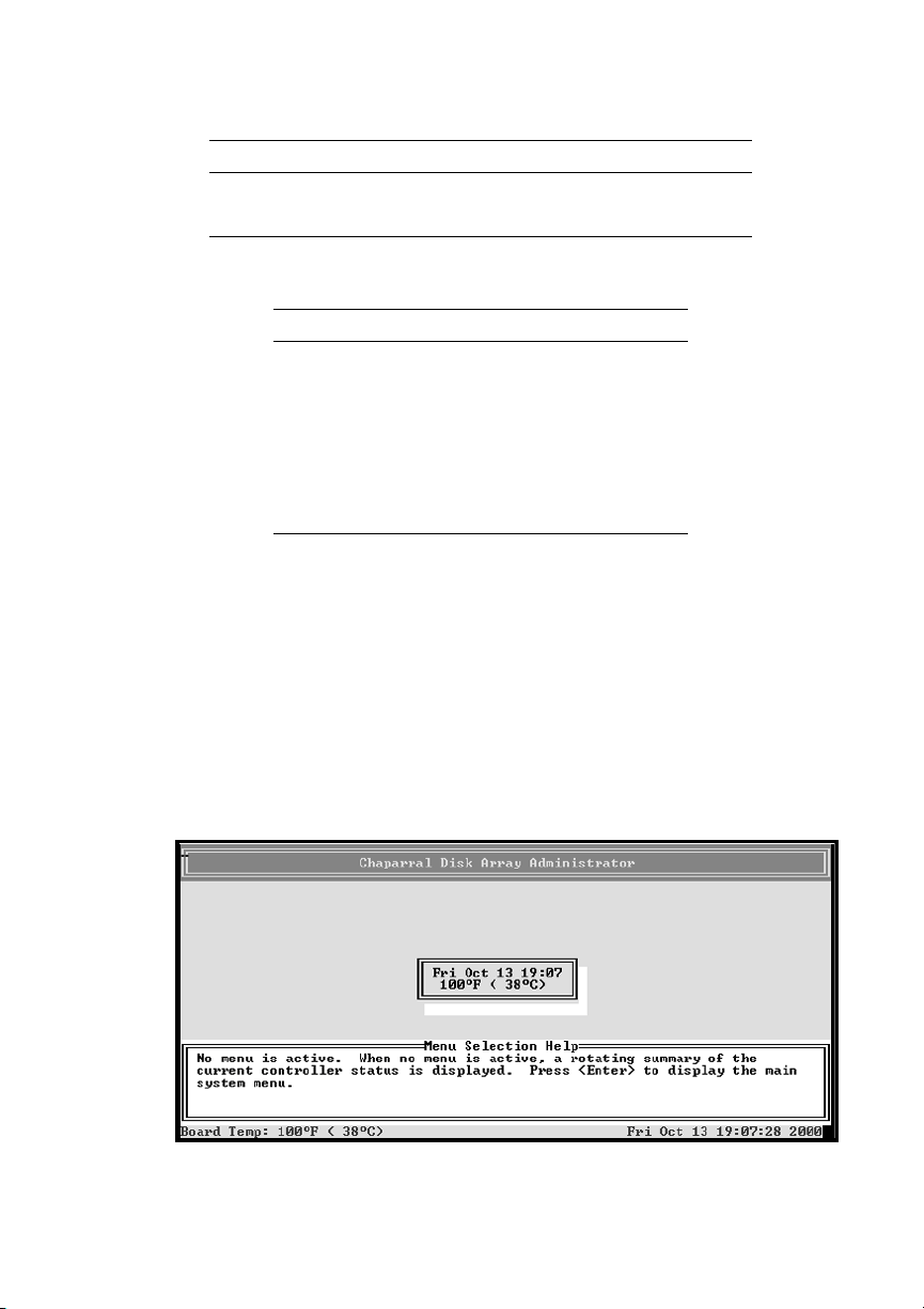
Press CTRL-R.
2
The initial Chaparral Disk Array Administrator screen displays.
3-2
Page 31
Accessing the Disk Array Administrator Software
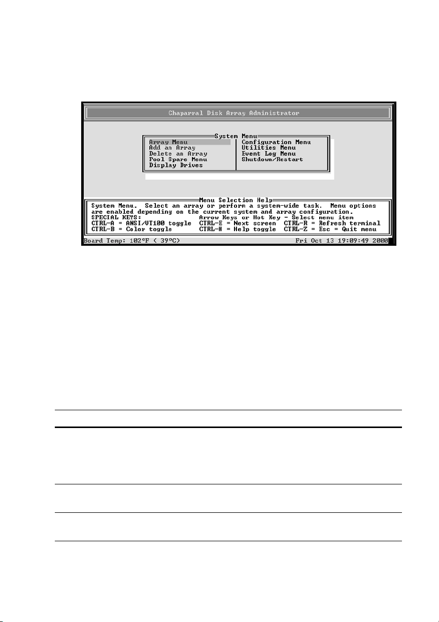
Press Enter.
3
The System Menu displays.
You can now perform all of the functions described in following chapters. All
steps start from the System Menu.
If an alarm condition has occurred, you will see a message about the problem.
This message will also be stored in the event log.
Navigating the Disk Array Administrator Software
You can navigate the Disk Array Administrator software using your keyboard.
Table 3-1 below describes the primary navigation and selection methods:
Table 3-1. Disk Array Administrator navigation
To Do t h is
Select a menu item Press the ↑ and ↓ and press Enter.
or
Press the letter that is a different color (or
highlighted) in a menu item (hot key).
Return to the previous menu or
screen without saving your changes
Scroll through the available choices
for a setting
Press Esc, CTRL+Z, or ←.
Press the ↑ and ↓.
3-3
Page 32

G- and K-Series User’s Guide
Note:
After four minutes of inactivity, the Disk Array Administrator
software times out and returns to the initial screen.
Changing the Screen Display
After you have accessed the Disk Array Administrator software, you can change the
screen display using a combination of keystrokes, as shown on the System Menu.
Table 3-2 lists the keystrokes required to change various screen displays.
Table 3-2. Changing screen displays
Select Function
Ctrl-A Toggles between ANSI and VT100 character sets
(use VT100 for legacy systems)
Ctrl-B Toggles between black and white and color screen
Ctrl-E Toggles between the event log, hardware
information, and configuration information screens
Ctrl-H Displays Help screen
Ctrl-R Refreshes screen
Ctrl-Z,
Esc, or ←
Escapes or quits menu
Disk Array Administrator Menu Tree
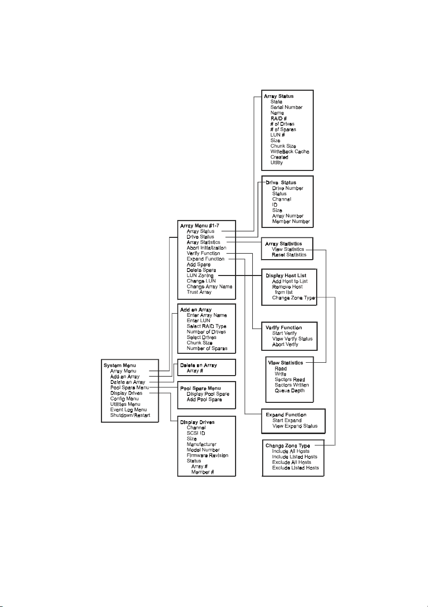
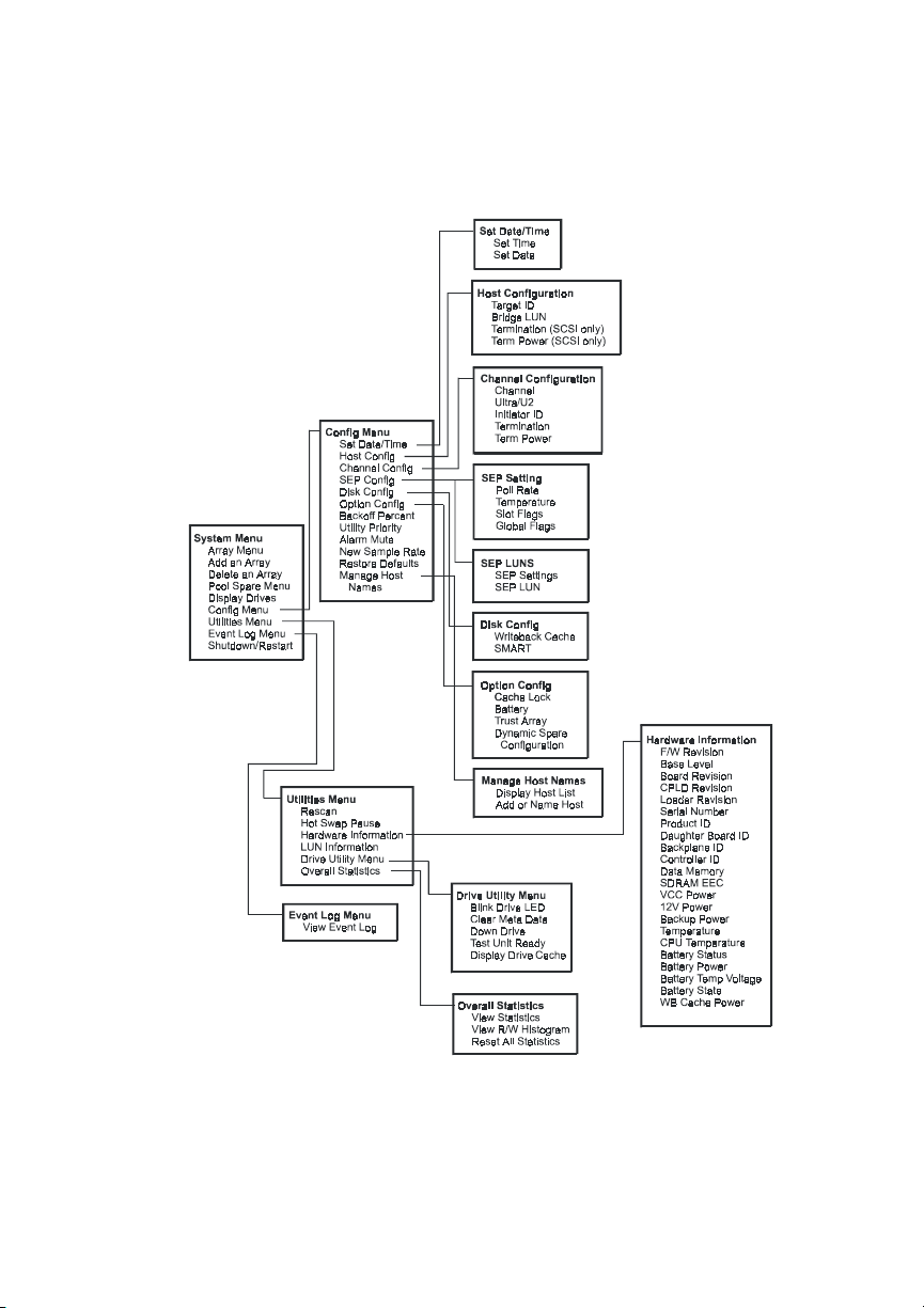
Figure 3-1 on page 3-5 and Figure 3-2 on page 3-6 describe the complete Disk Array
Administrator menu hierarchy. In the Disk Array Administrator, menu options that
are not accessible appear gray. For example, the Array Menu is not accessible unless
one or more arrays exist.
3-4
Page 33
Accessing the Disk Array Administrator Software
Figure 3-1. Menu tree
3-5
Page 34
G- and K-Series User’s Guide
❒
3-6
Figure 3-2. Menu tree (continued)
Page 35

4
Creating and Managing Arrays
Using the Disk Array Administrator, you can create and manage arrays. You can
perform the following array-related functions:
Create arrays (see page 4-1)
!
View array and drive status (see page 4-8)
!
Stop the initialization process (see page 4-14)
!
Verify an array (see page 4-15)
!
Reconstruct an array (see page 4-17)
!
Expand array capacity (see page 4-18)
!
Change the array Logical Unit Number (LUN) (see page 4-21)
!
Change the array name (see page 4-22)
!
Trust an array (see page 4-22)
!
Delete an array (see page 4-24)
!
Creating Arrays
You can create an array anytime. The following table describes the drive
requirements for each RAID level.
Table 4-1. Drive requirements by array type
Minimum
RAID Level
Vo l u me S e t 1 1
0216
3316
4316
No. of
Drives
Maximum
No. of
Drives
4-1
Page 36
G- and K-Series User’s Guide
Table 4-1. Drive requirements by array type (Continued)
Note:
Minimum
No. of
RAID Level
5316
50 6 16
Mirrored 2 16
Drives
Before you create more than one array, you must be sure that your
Maximum
No. of
Drives
host operating system supports multiple Logical Unit Numbers (LUNs).
Most operating systems do, or have an option you can enable to support
multiple LUNs. If your operating system does not support multiple LUNs,
the host will only be able to see one array.
To create an array:
From the System Menu, select Add an Array and press Enter.
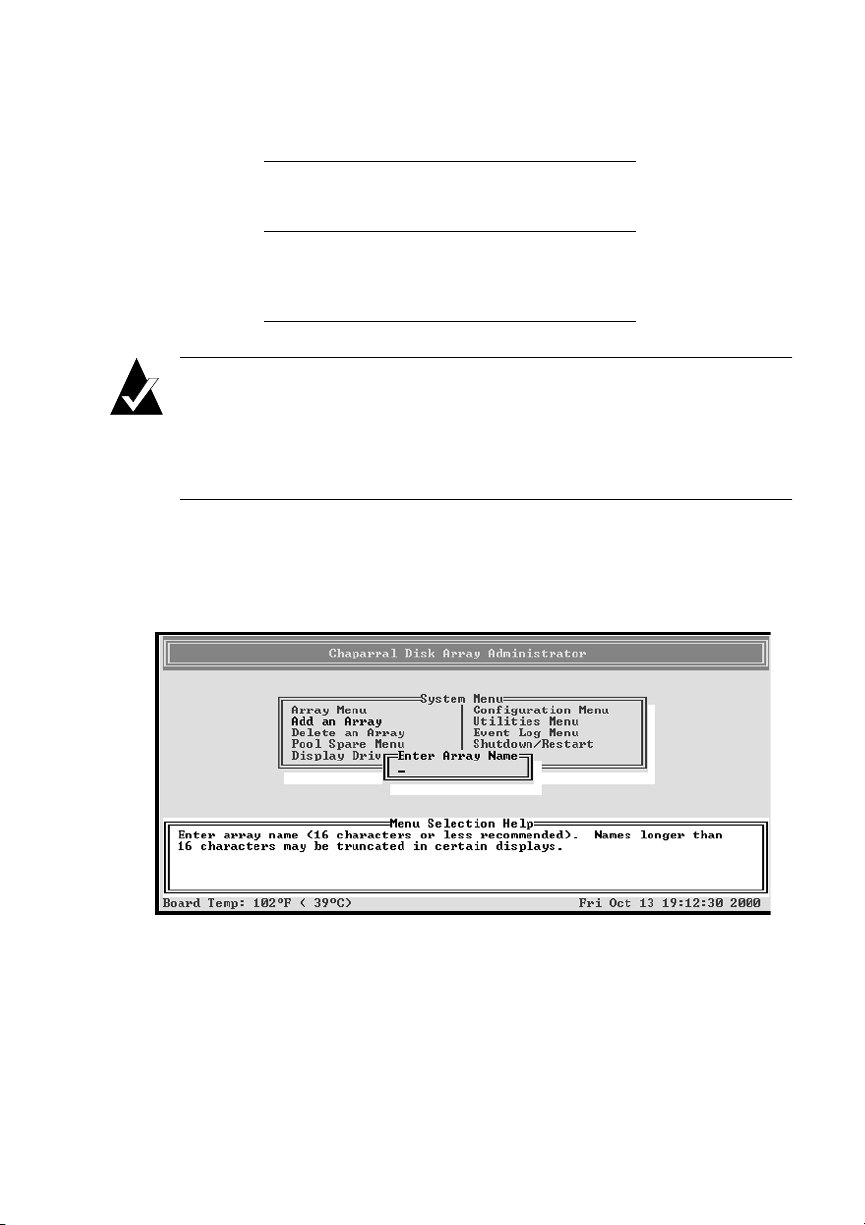
1
The Enter Array Name screen displays.
Enter a name for the array and press Enter.
2
You can use up to 35 characters. You can include any characters in the name,
including spaces.
4-2
Page 37
Creating and Managing Arrays
If you do not want to name the array, you can just press Enter. You can add or
change the name later.
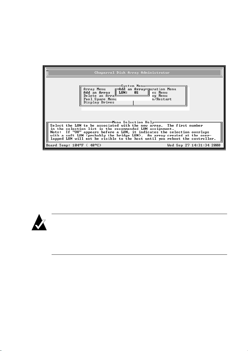
The LUN screen displays.
Select the LUN for the array and press Enter.
3
The LUN that displays is the suggested default LUN assignment.
If the letters OV appear before a LUN, it indicates that the selection overlaps
with a soft LUN, probably the controller or SAF-TE Environmental Processor
(SEP) LUN. You can create an array at an overlapped LUN, but it is not visible
to the host system until you reboot the controller.
Note:
controller LUN be a higher value than all array LUNs. Before creating your
first array, change the controller LUN to a higher value or choose NONE
(best choice) if you are not using CAPI to manage the arrays. This allows
your first array to be seen at LUN 0.
The system warns you about the LUN for UNIX and Macintosh, as above, the
first time you create an array. Press Enter and the system asks if you want to be
warned again. Select No to avoid receiving this warning again, otherwise select
Ye s to be warned the next time you create an array.
Most Unix, Linux, and Macintosh operating systems require the
4-3
Page 38
G- and K-Series User’s Guide
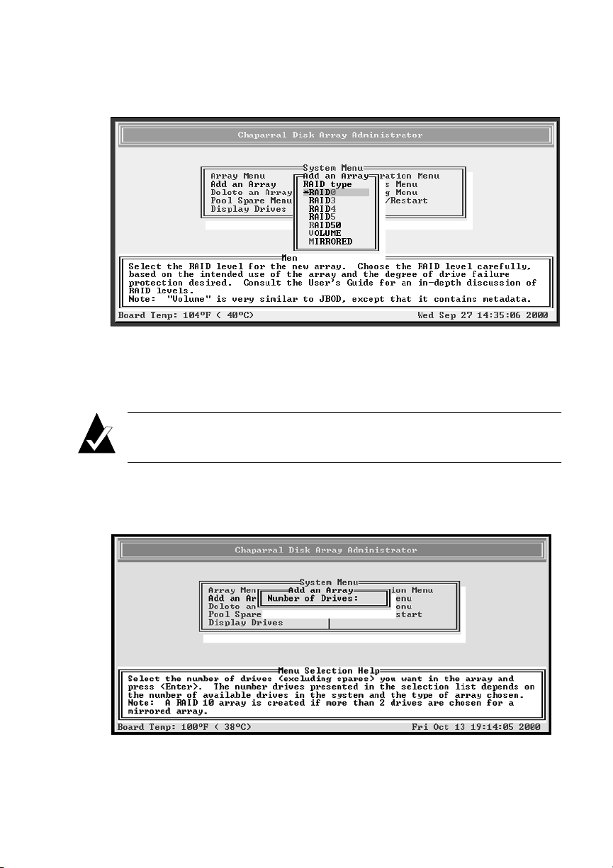
The RAID Type screen displays.
Select the array type: RAID0, RAID3, RAID4, RAID5, RAID50, VOLUME
4
(a single drive similar to just a bunch of disks (JBOD) except that it includes
metadata), or MIRRORED and press Enter.
Note:
mirrored array.
See Appendix A,
The Number of Drives screen displays.
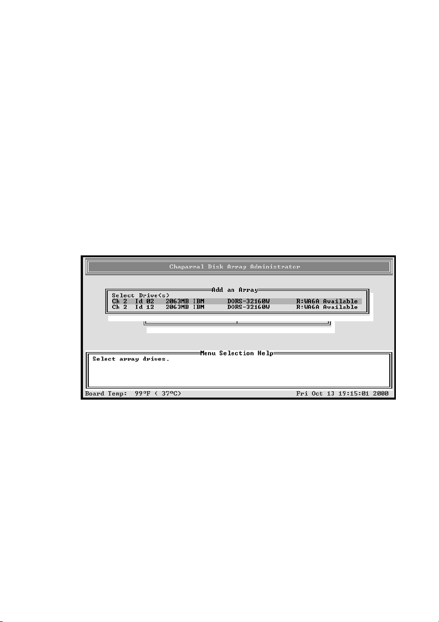
4-4
A RAID 10 array is created when there are more than two drives in a
Array Basics
for more information.
Page 39
Creating and Managing Arrays
Enter the number of drives (excluding spares) you want in the array and press
5
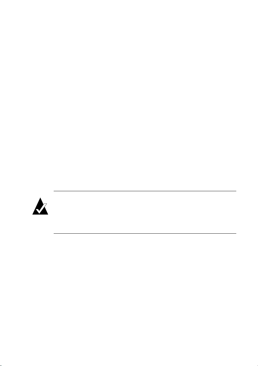
Enter.
The Select Drives screen displays with a list of all available drives, including
the following information about each drive:
– Channel
–SCSI ID
– Drive capacity
– Drive manufacturer
– Drive model number
– Drive firmware revision
–Drive state
Select the drives you want to use for the array and press Enter.
6
You select a drive by highlighting it and pressing Enter. Each selected drive
turns gray in the drive list. After you press Enter for the number of drives you
entered previously, the system automatically goes to the next screen. To skip a
drive, use the
If the array is mirrored, RAID 3, RAID 4, RAID 5, or RAID 50
one or more drives left, the Number of Spares screen displays.
↑ or ↓
keys.
and
you have
4-5
Page 40

G- and K-Series User’s Guide
If the Number of Spares screen displays, enter the number of spares you want to
7
add and press Enter.
This creates dedicated spares that can only be used by this array. A dedicated
spare drive will not be available for any other use. For more information about
spares, see Chapter 6, Managing Spares.
If you do not want a spare, enter 0.
The Select Drives screen displays.
If the Select Drives screens displays, select the drive you want to use as a
8
dedicated spare and press Enter.
Only available drives, that is, drives that are not members of an array and are
not assigned as a dedicated or pool spares, display. You can delete a dedicated
spare from the array at any time. For more information see, Deleting a
Dedicated Spare on page 6-3.
You select a drive by highlighting it and pressing Enter. Each selected drive
turns gray in the drive list. After you press Enter for the number of drives you
entered previously, the system automatically goes to the next screen. To skip a
drive, use the
If the array you are creating is a RAID 3, RAID 4, RAID 5, or RAID 50, the
Chunk Size screen displays.
↑ or ↓
keys.
If the Chunk Size screen displays, select the chunk size and press Enter.
9
The chunk size is the amount of contiguous data that is written to an array
member before moving to the next member of the array. To determine the
4-6
Page 41
Creating and Managing Arrays
appropriate chunk size, refer to your operating system documentation. For
example, the default chunk size for Windows NT and many other operating
systems is 64 KB. If you are using the array for a database with very small
records, you may want to use a smaller chunk size.
The system confirms that you want to create the array.
Select Ye s and press Enter.
10
A message notifies you that the array is being created and shows the progress of
the initialization process. The array initialization process takes from several
minutes to more than an hour depending on the array type (volume, RAID 0,
and RAID 1 are the fastest), array size, drive speed, and other processes running
on the controller.
You can press Esc to return the Disk Array Administrator menus and perform
other functions. To check the progress of the array initialization, select Array
Menu from the System Menu. The status of the initialization displays in the list
of arrays.
If you find that you need to change the disks or some other array configuration,
you can stop the array initialization process. See Stopping the Array
Initialization Process
on page 4-14.
Note:
reboot the host system to see the new array. NetWare v3.12 and higher can
recognize new devices by typing the command SCAN FOR NEW
DEVICES at the console prompt. Other operating systems might have
similar features.
Most operating systems, such as Windows NT 4.0, require you to
4-7
Page 42

G- and K-Series User’s Guide
Managing Arrays
The Disk Array Administrator software lets you manage your arrays in a variety of
ways. You can:
View array and drive status (see page 4-8)
!
Stop the initialization process (see page 4-14)
!
Verify an array (see page 4-15)
!
Reconstruct an array (see page 4-17)
!
Expand array capacity (see page 4-18)
!
Change the array LUN (see page 4-21)
!
Change the array name (see page 4-22)
!
Trust an array (see page 4-22)
!
Delete an array (see page 4-24)
!
Viewing Array Status
You can view the status of an array, including the following information:
State—Online, Offline, Critical, or Fault-tolerant.
!
Name—The name given to the array.
!
RAID—RAID type (0, 3, 4, 5, 50, Volume, or Mirrored). The term “mirrored”
!
is used for both RAID 1 and RAID 10 arrays.
# of Drives—Number of drives in the array when fault-tolerant. For example, if
!
you create a three-drive RAID-5 array and lose one drive, the number will still
display 3.
# of Spares—Number of spare drives dedicated to this array.
!
LUN #—LUN presented to the host system.
!
Size—Size of the entire array (expressed in MB or GB for arrays larger than
!
10 GB).
Chunk size—The array’s chunk size.
!
4-8
Page 43
Creating and Managing Arrays
WBcache—Status of the write-back cache (enabled or disabled) for this array.
!
Created—Date the array was created.
!
Utility—Utility running (None, Verify, Reconstruct, Expand, or Initialize).
!
To view the status of an array:
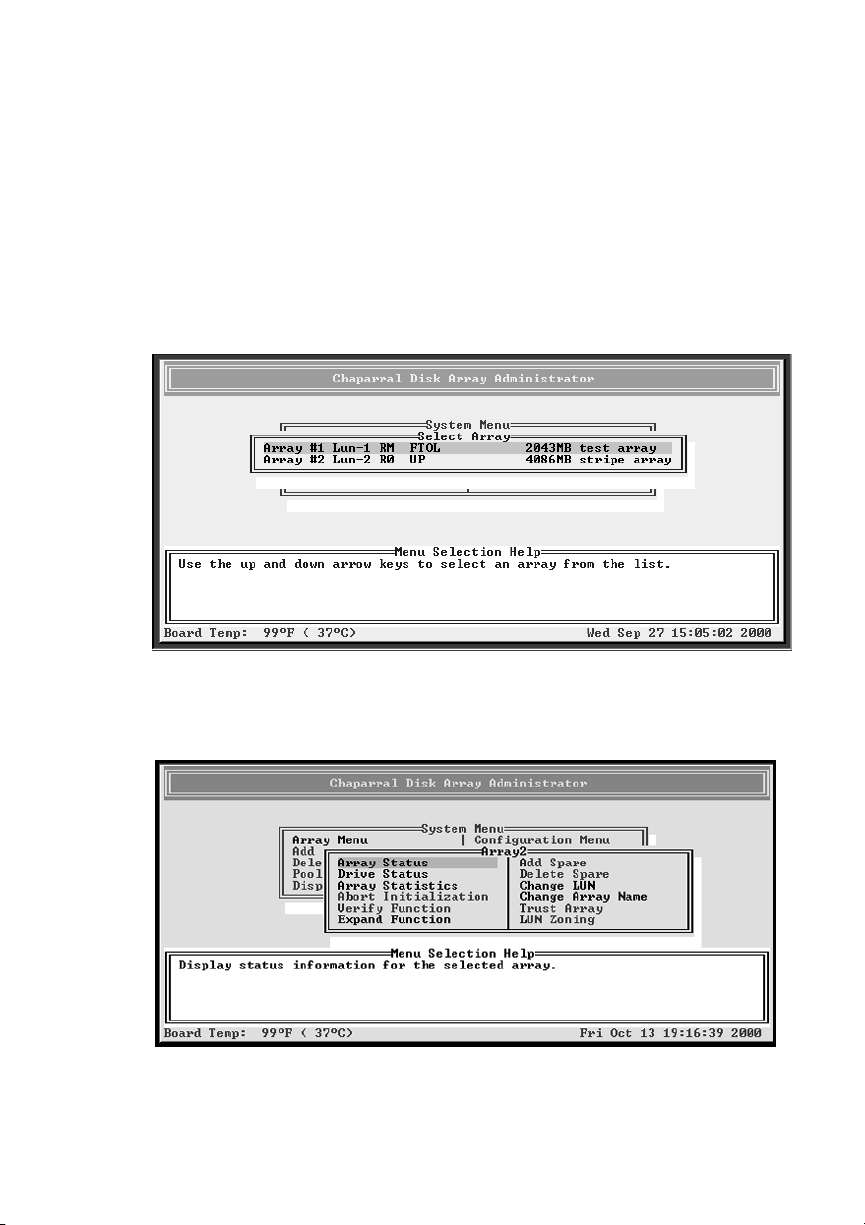
From the System Menu, select Array Menu and press Enter.
1
The Select Array screen displays with a list of existing arrays.
Select the array you want and press Enter.
2
The Array Menu screen displays.
4-9
Page 44
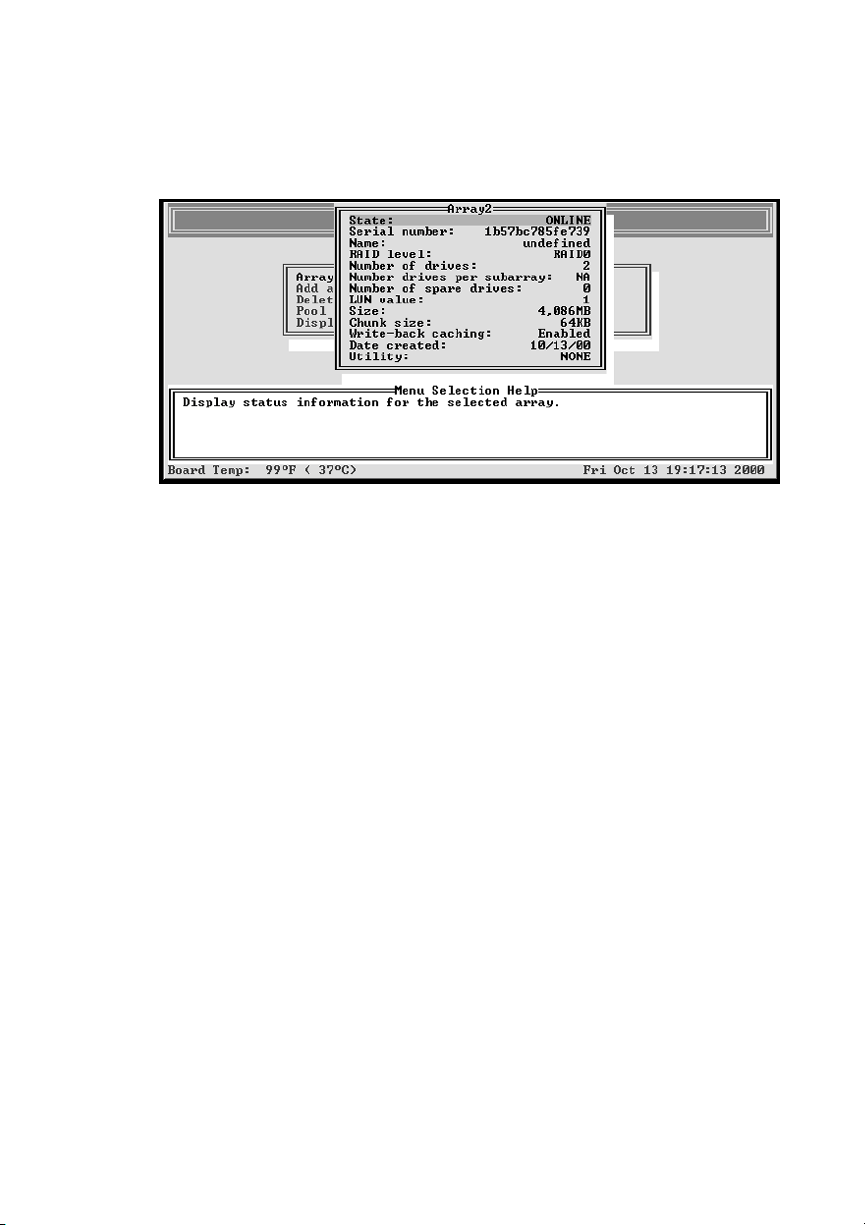
G- and K-Series User’s Guide
Select Array Status and press Enter.
3
The status screen displays showing the status of the array you selected.
Press Esc to return to the Array Menu.
4
Viewing Array Statistics
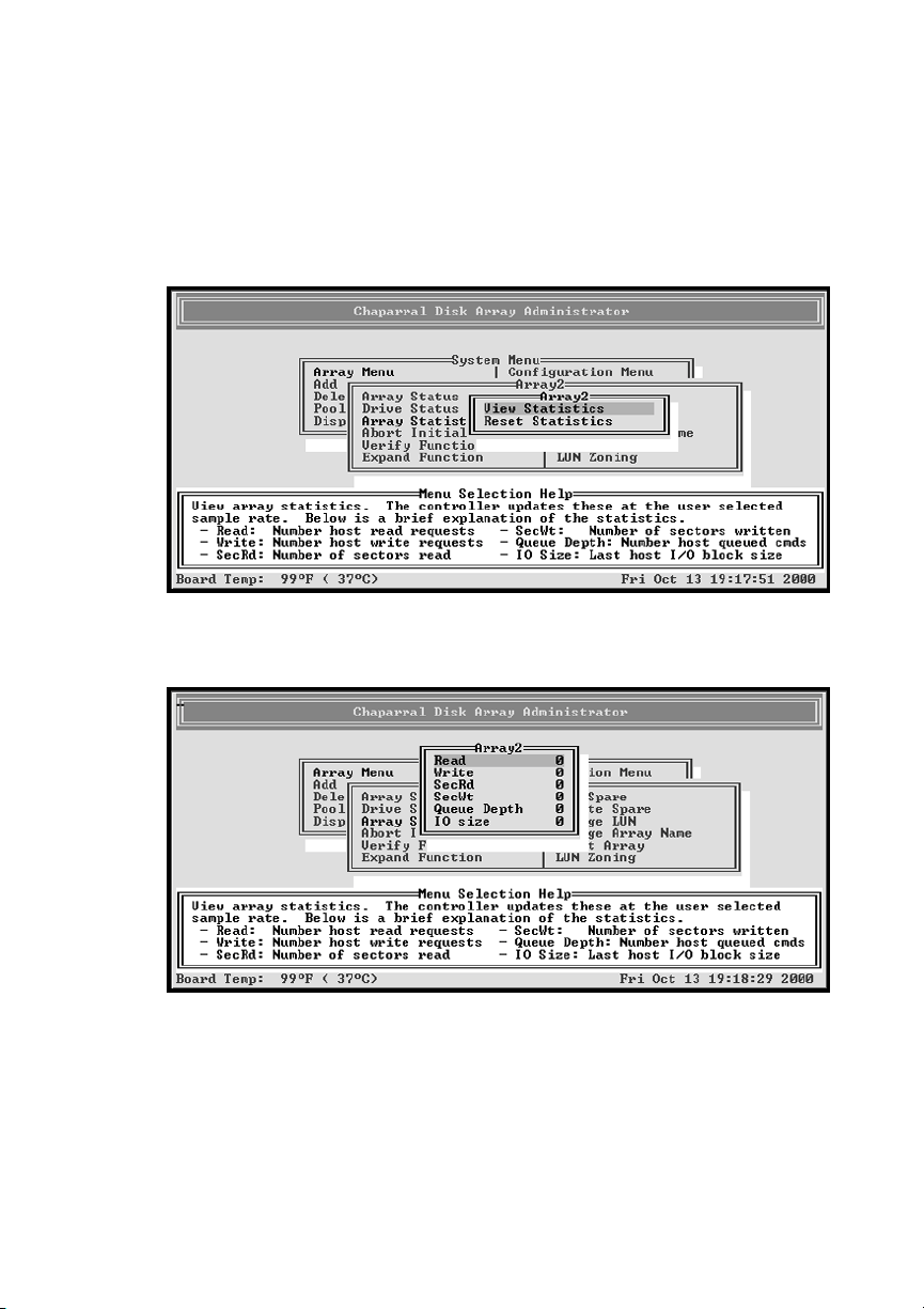
You can view the current array statistics. The following statistics are available:
Read—Total number of host read requests directed to the array
!
Write—Total number of host write requests directed to the array
!
SecRd—Total number of sectors read from the array
!
SecWt—Total number of sectors written to the array
!
Queue Depth—Current number of commands from the host that are queued up
!
I/O Size—Last host I/O block size request in 512-byte sectors
!
Similar statistics are also available on an aggregate basis for all array LUNs. For more
information, see
Displaying Overall Statistics
on page 5-11.
To view the array statistics:
From the System Menu, select Array Menu and press Enter.
1
The Select Array screen displays with a list of existing arrays.
4-10
Page 45
Creating and Managing Arrays
Select the array you want and press Enter.
2
The Array Menu screen displays.
Select Array Statistics and press Enter.
3
The statistics menu screen displays.
Select View Statistics and press Enter.
4
The statistics screen displays showing the statistics of the array you selected.
Press Esc to return to the statistics menu.
5
4-11
Page 46
G- and K-Series User’s Guide
Resetting Array Statistics
You can reset the follow array statistics to zero:
Read
!
Write
!
SecRd
!
SecWt
!
I/O Size
!
Note:
included in the aggregate statistics. See Displaying Overall Statistics on
page 5-11.
You may want to reset the statistics if you are monitoring performance or doing
benchmark testing. You may also want to reset statistics when you change how you
are using the array.
Note:
I/O queue depth.
To reset array statistics:
From the System Menu, select Array Menu and press Enter.
1
The Select Array screen displays with a list of existing arrays.
Select the array you want and press Enter.
2
The Array Menu screen displays.
Select Array Statistics and press Enter.
3
The statistics menu screen displays.
Select Reset Statistics and press Enter.
4
Resetting statistics here also resets the statistics for this array that are
You cannot reset the queue depth value. It always reflects the current
The system confirms that you want to make the change.
Select Ye s and press Enter.
5
The system confirms that the statistics have been cleared and returns to the
statistics menu.
4-12
Page 47

Creating and Managing Arrays
Viewing Drive Status
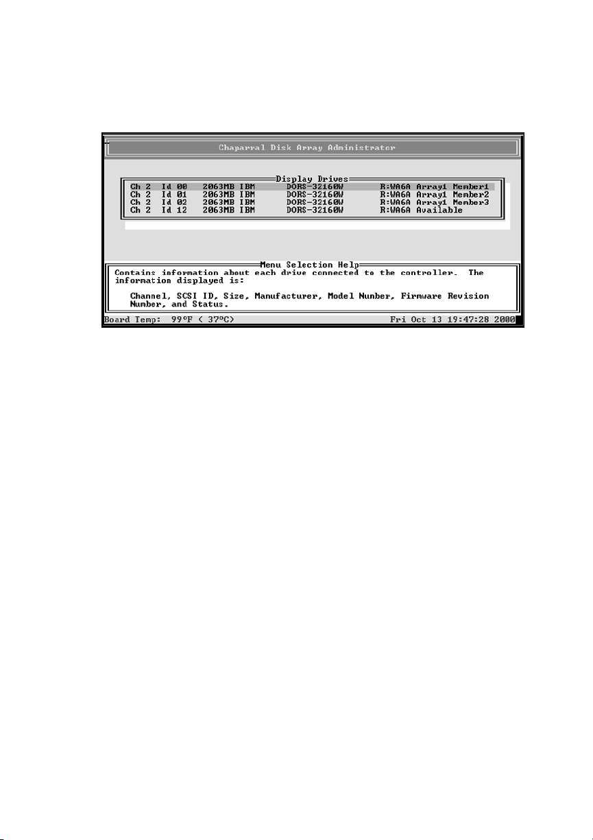
You can view the status of the drives in an array, including the following information:
Drive number—This drive’s sequential position in the controller’s drive list
!
Drive status—Whether the drive is up or down
!
Channel number—Back-end disk bus number
!
Target ID
!
Size—Size of the drive in MB
!
Status—If part of an array, this displays the array name and member number. If
!
a spare, this displays the type of spare. If unused, displays Available. If drive
was part of an array that no longer exists, displays Leftover.
Note:
If a drive has failed or malfunctioned, it may not be listed.
To view drive status:
From the System Menu, select Array Menu and press Enter.
1
The Select Array screen displays with a list of existing arrays.
Select the array you want and press Enter.
2
The Array Menu screen displays.
Select Drive Status and press Enter.
3
4-13
Page 48
G- and K-Series User’s Guide
The drive status screen displays showing the drives that are members of the
array and that are assigned as dedicated spares.
Use the
are currently members of the array.
Press Esc to return to the Array Menu.
4
arrow keys to scroll through the drives. These are the drives that
↑ or ↓
Stopping the Array Initialization Process
If you find that you need to change the disks or some other array configuration, you
can stop the array initialization process.
After you stop the process, the array is marked as offline and cannot be used. You
must delete the array before you can use the drives in another array.
To stop the array initialization process:
From the System Menu, select Array Menu and press Enter.
1
The Select Array screen displays with a list of existing arrays.
Select the array you want and press Enter.
2
The Array Menu screen displays.
Select Abort Initialization and press Enter.
3
The system confirms that you want to stop the initialization process.
Select Ye s and press Enter.
4
4-14
Page 49
Creating and Managing Arrays
Verifying an Array
The Verify function allows you to verify the data on the specified array (RAID 3,
RAID 4, RAID 5, RAID 50, and mirrored arrays only):
RAID 3, RAID 4, RAID 5, and RAID 50—Verifies all parity blocks in the
!
selected array and corrects any bad parity.
Mirrored—Compares the primary and secondary drives. If a mismatch occurs,
!
the primary is copied to the secondary.
You may want to verify an array when you suspect there is a problem.
To verify an array:
From the System Menu, select Array Menu and press Enter.
1
The Select Array screen displays with a list of existing arrays.
Select the array you want and press Enter.
2
The Array Menu screen displays.
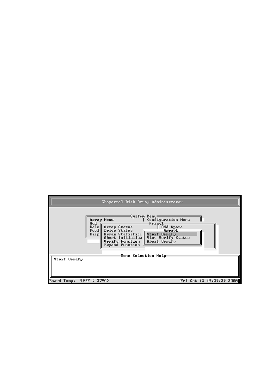
Select Verify Function and press Enter.
3
The verify menu displays.
4-15
Page 50
G- and K-Series User’s Guide
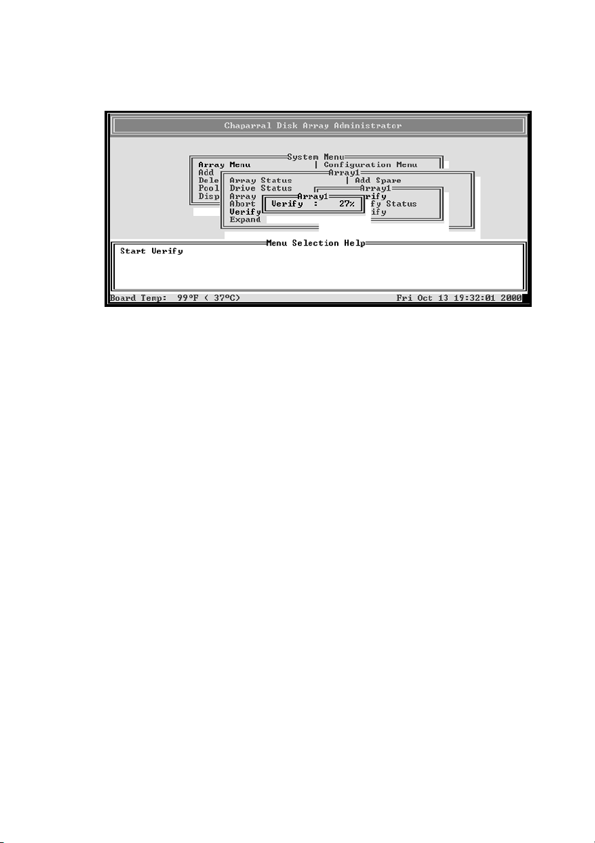
Select Start Verify and press Enter.
4
Verification begins and the percentage of verification completed displays. You
can continue to use the array during verification.
To return to the verification menu, press Esc. To check the progress of the array
verification, you can use the verification status described below or select Array
Menu from the System Menu. The status of the verification displays in the list
of arrays.
Viewing Verification Status
You can view the status of the verification process while it is running.
To view verification status:
From the System Menu, select Array Menu and press Enter.
1
The Select Array screen displays with a list of existing arrays.
Select the array you want and press Enter.
2
The Array Menu screen displays.
Select Verify Function and press Enter.
3
The verify menu displays.
Select View Verify Status and press Enter.
4
The Verify Status screen displays.
Press Esc to return to the verify menu.
5
4-16
Page 51

Creating and Managing Arrays
Stopping the Verification
You can stop the verification process. Normally, you want to let the verification
finish, though stopping it does not cause any damage to your data. You may want to
stop the verification if you want improve performance of the controller for another
application.
To stop the verification process:
From the System Menu, select Array Menu and press Enter.
1
The Select Array screen displays with a list of existing arrays.
Select the array you want and press Enter.
2
The Array Menu screen displays.
Select Verify Function and press Enter.
3
The verify menu displays.
Select Abort Verify and press Enter.
4
The system confirms that you want to stop the verification process.
Select Ye s and press Enter.
5
Reconstructing an Array
The controller automatically reconstructs redundant arrays (RAID 3, RAID 4, RAID
5, RAID 50, and mirrored) if an array becomes critical and a properly sized spare
drive is available. An array becomes critical when one or more member drives fails.
If a reconstruct does not start automatically, it means that no valid spares are
available. To start a reconstruct, replace the failed drive, and then add it as a spare
(see Adding a Dedicated Spare on page 6-2, and Enabling Dynamic Spares on
page 6-3) or as a pool spare (see Adding a Spare to the Spare Pool on page 6-5).
Remember that any pool spares added might be used by any critical array, not
necessarily the array you want.
4-17
Page 52
G- and K-Series User’s Guide
Expanding Array Capacity
You can expand array capacity without stopping I/O activity, so you can continue
using the array while the expansion process runs. You can only expand one array at a
time.
Note:
Expanding an array here does not change the size of the host
operating system partitions that reside on the array, because our controller is
working at the block level not the file system level of the operating system.
To use the new space, you must create a new partition using the newly added
space or use a third party application specific to the operating system to
change the partition size.
How you create a new partition or resize an existing one depends upon the
operating system. Most operating systems cannot resize an existing partition.
Refer to your operating system documentation.
The number of drives you can add to an array depends upon the RAID level as shown
below. You also cannot exceed the maximum number of drives for each RAID level.
See
Creating Arrays
on page 4-1.
Table 4-2. Drive additions by RAID level
RAID Level
RAID 0 1 to 4
RAID 1 (mirrored) Cannot expand
Volume Set Cannot expand
RAID 10 2 or 4
RAID 3, 4, or 5 1 to 4
RAID 50 3 to 5
Number of Drives You
Can Add
4-18
Note:
Once you start expanding array capacity, you cannot stop it. The
expand function may take an hour or more to complete, depending on the
array type, array size, drive speed, and other processes running on the
controller.
Page 53
Creating and Managing Arrays
To expand an array:
From the System Menu, select Array Menu and press Enter.
1
The Select Array screen displays with a list of existing arrays.
Select the array you want and press Enter.
2
The Array Menu screen displays.
Select Expand Function and press Enter.
3
The expand menu displays.
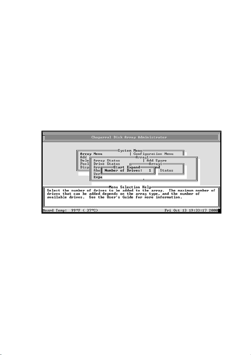
Select Start Expand and press Enter.
4
The Number of Drives screen displays.
Enter the number of drives you want to add and press Enter.
5
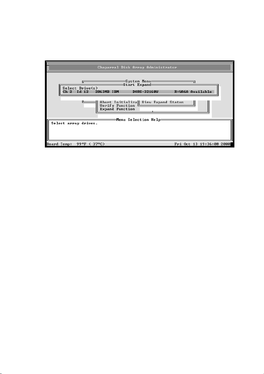
The Select Drives screen displays.
4-19
Page 54
G- and K-Series User’s Guide
Press Enter.
6
The list of available drives screen displays.
Select the drives you want to add from the list of available drives and press
7
Enter.
Only available drives, that is, drives that are not members of an array and are
not assigned as a dedicated or pool spares, display.
You select a drive by highlighting it and pressing Enter. Each selected drive
turns gray in the drive list. After you press Enter for the number of drives you
entered previously, the system automatically begins the expansion. To skip a
drive, use the
↑ or ↓
keys.
Expansion begins and the percentage completed displays. To return to the Array
Menu, press Esc. To check the progress of the expansion, you can use the
expand status described below or select Array Menu from the System Menu.
The status of the expansion displays in the list of arrays.
Viewing Expand Status
You can view the status of the expansion process while it is running.
To view expand status:
From the System Menu, select Array Menu and press Enter.
1
The Select Array screen displays with a list of existing arrays.
Select the array you want and press Enter.
2
The Array Menu screen displays.
4-20
Page 55
Creating and Managing Arrays
Select Expand Function and press Enter.
3
The expand menu displays.
Select View Expand Status and press Enter.
4
The Expand Status screen displays.
Press Esc to return to the expand menu.
5
Changing the Array LUN
You can change the LUN assigned to an array, as it appears under the controller’s
target ID from the host system’s point of view. The change takes place immediately,
however, you may need to reboot the host system to see the array at the new LUN.
Note:
you want to use a LUN that is already in use, you must first reassign the
LUN in use.
For more information about LUNs and your controller, see
page 7-4.
To change the array LUN:
From the System Menu, select Array Menu and press Enter.
1
The Select Array screen displays with a list of existing arrays.
Select the array you want and press Enter.
2
The Array Menu screen displays.
Select Change LUN and press Enter.
3
The New LUN screen displays.
Enter the LUN you want to use and press Enter.
4
The system confirms that you want to make the change.
Select Ye s and press Enter.
5
You cannot change the array’s LUN to one that is already in use. If
Understanding LUNs
on
4-21
Page 56

G- and K-Series User’s Guide
Changing the Array Name
You can change the name of the array. This does not affect the target ID or LUN
values of the array. The controller does not allow you to change an array name when a
utility is running.
To change the array name:
From the System Menu, select Array Menu and press Enter.
1
The Select Array screen displays with a list of existing arrays.
Select the array you want and press Enter.
2
The Array Menu screen displays.
Select Change Array Name and press Enter.
3
The Enter New Name screen displays.
Enter the name you want to use and press Enter.
4
You can use up to 35 characters. You can include any characters in the name,
including spaces.
The system confirms that you want to make the change.
Select Ye s and press Enter.
5
Trusting an Array
You can use the Trust Array function to bring an array back online by resynchronizing
the time and date stamp and any other metadata on a bad disk. This makes the disk an
active member of the array again. You might need to do this when:
One or more disks of an array start up more slowly or were powered on after the
!
rest of the disks in the array. This causes the date and time stamps to differ,
which the controller interprets as a problem with the “late” disks. In this case,
the array will function normally after using Trust Array.
An array is offline because a drive is failing, you have no data backup, and you
!
want to try to recover the data from the array. In this case, the Trust Array
function may work, but only as long as the failing drive continues to operate.
Before you can use this function, you must enable it in the Option Configuration
menu.
4-22
Page 57
Creating and Managing Arrays
Caution:
if used improperly. This feature is intended for disaster recovery.
!
To trust an array:
From the System Menu, select Configuration Menu and press Enter.
1
The Configuration Menu displays.
Selection Option Configuration and press Enter.
2
The Option Configuration Menu displays.
Select Enable Trust Array and press Enter.
3
The Enable Trust Array screen displays.
Select Enable and press Enter.
4
The option is only enabled until you use it. After you trust an array, the option
reverts back to being disabled.
Press Esc twice to return to the System Menu.
5
Select Array Menu and press Enter.
6
The Select Array screen displays with a list of existing arrays.
Select the array you want and press Enter.
7
The Array Menu screen displays.
The trust array feature can cause unstable operation and data loss
Select Trust Array and press Enter.
8
The system confirms that you want to trust the array.
Select Ye s and press Enter.
9
The array will be back online.
Note:
members are offline or the array may have additional failures on the bus or
enclosure that Trust Array cannot fix.
If the array does not come back online, it may be that too many
4-23
Page 58
G- and K-Series User’s Guide
Deleting an Array
You can delete an array when you no longer need the array or you need the drives for
another use.
Caution:
however, before reusing the drives, you should do a low-level format on
!
each drive.
Note:
Expand, or Reconstruct) is running on the array. You must stop the utility, if
allowed, or let it finish before you can delete the array.
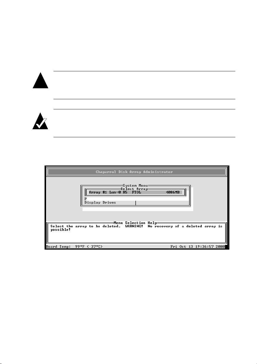
To delete an array:
From the System Menu, select Delete an Array and press Enter.
1
Deleting an array deletes the data contained in the array;
You cannot delete an array while any utility (Initialize, Verify,
A list of arrays appears in the menu, if more than one array is exists.
Select the array you want to delete and press Enter.
2
The system asks you to confirm the deletion.
Select Ye s and press Enter.
3
❒
4-24
Page 59

5
Monitoring System Status
You should monitor your system regularly to ensure that the controller, disks, and
arrays are working properly. The Disk Array Administrator software lets you monitor
the status several ways:
Event log (see below)
!
Hardware information (see Displaying Hardware and Configuration
!
Information on page 5-5)
Array status screen (see
!
Disk status screen (see
!
Power On Self-Test (POST) (see
!
Overall Statistics screen (see
!
Viewing Array Status
Viewing Drive Status
Problems During Bootup
Displaying Overall Statistics
on page 4-8)
on page 4-13)
on page 9-4)
on page 5-11)
Displaying the Event Log
The controller’s event log contains important information about the status of the
controller, disks, and arrays. You should check it regularly to monitor the status of
your system. For more information about specific SCSI disk and channel errors, see
Understanding SCSI Errors on page 9-9.
Below is a list of some of the key warning and failure events included in the log
during operation:
Disk detected error
!
Disk channel error
!
Battery failure
!
Drive down
!
Power up
!
5-1
Page 60
G- and K-Series User’s Guide
Array critical
!
Array offline
!
Temperature warning
!
Temperature failure (this leads to a shutdown which is also logged)
!
Voltage warning
!
Voltage failure (this leads to a shutdown which is also logged)
!
The event log stores the most recent 400 events. Events are numbered sequentially
from 001 to 999. The numbering wraps back to 001 after reaching 999.
Note:
If you are having a problem with the controller or an array, check the
event log before calling technical support. Event messages may let you
resolve the problem without calling. You should also check Chapter 9,
Troubleshooting.
You can view the event information three ways:
Most recent event
!
One event at a time, most recent event first
!
Full page of events at a time
!
You can also capture the event log to a file. See
Capturing the Event Log File
on
page 5-4.
Viewing the Most Recent Event
The most recent voltage or temperature event displays in rotation with the date and
time whenever the Disk Array Administrator times out and returns to its initial screen.
Viewing One Event at a Time
You can view controller-related events one at a time. The events display in reverse
chronological order, that is, the most recent event is first.
5-2
Page 61
Monitoring System Status
To display one event at a time:
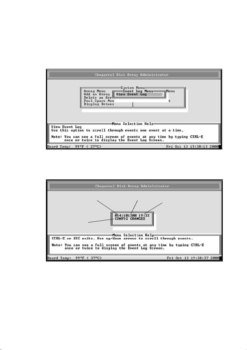
From the System Menu, select Event Log Menu and press Enter.
1
The Event Log Menu screen displays.
Select View Event Log and press Enter.
2
The Event Log screen displays the last event that occurred.
Sequential event
number
Event
Press ↑ to see the previous event.
3
You can continue to view earlier events by pressing
Press Esc to return to the Event Log Menu.
4
Event date
Event time
.
↑
5-3
Page 62
G- and K-Series User’s Guide
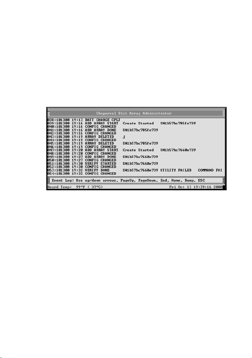
Viewing a Whole Screen of Events
You can also view events from the log file a whole screen at time. This lets you
quickly review all recent events. The events display in chronological order, that is, the
most recent event is last.
To display a whole screen of events:
From anywhere in the Disk Array Administrator software, press CTRL-E.
1
The first screen of events from the event log displays.
Press u to page up or d to page down in the log.
2
Keep pressing CTRL-E to page through the other information screens and
3
return to the menu.
Capturing the Event Log File
You can also capture the entire event log, which saves it to a file on your hard drive.
This is useful if you want to print the log or attach it to an e-mail message.
The steps below use HyperTerminal as the terminal emulator software. If you use a
different terminal emulator, your procedure may be different.
To capture the event log file:
With HyperTerminal up and running as your RS-232 interface terminal, press
1
CTRL-E until the event log displays.
5-4
Page 63

Monitoring System Status
From the Transfer menu in HyperTerminal, select Capture Text.
2
The Capture Text window displays.
Enter the path and file name you want to use to store the log file contents.
3
Click Start.
4
Press P on the keyboard to begin the transfer.
5
From the Transfer menu in HyperTerminal, select Capture Text.
6
The Capture Text window displays.
Click Stop.
7
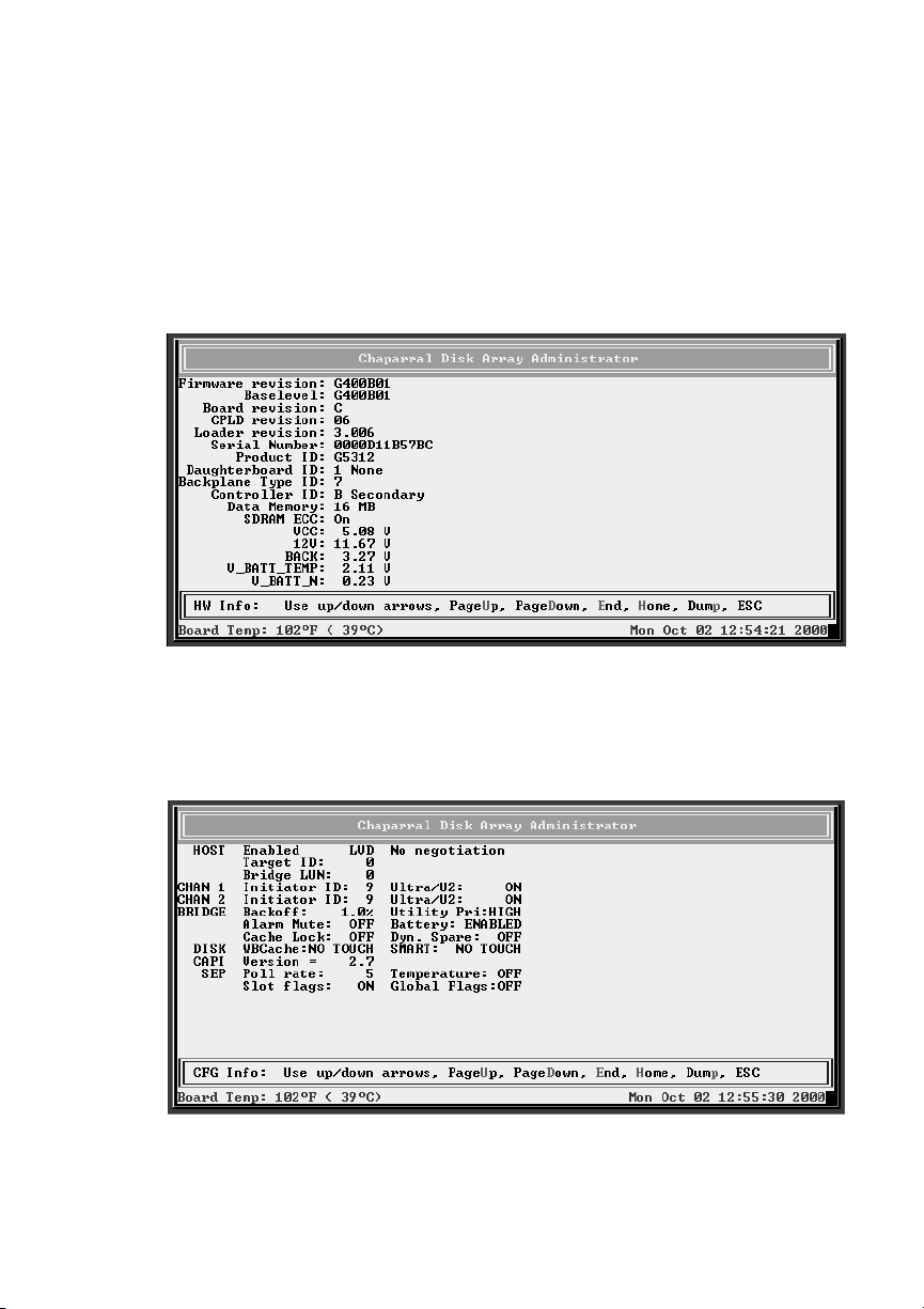
Displaying Hardware and Configuration Information
You can display the controller’s hardware and configuration information. This is
where you can see what version of the firmware you have. Chaparral technical
support personnel may request this information.
You can display the hardware and configuration information two ways:
Hardware information only
!
Hardware and configuration information
!
Table 5-1 lists the configuration information that is available.
Table 5-1. Configuration information
Group Field What displays Field What displays
HOST Enabled Field is just a
placeholder.
Target ID SCSI ID of
controller as set in
the Disk Array
Administrator
software.
SE/LVD
(K5312 and
G5312 only)
Negotiation rate.
5-5
Page 64

G- and K-Series User’s Guide
Table 5-1. Configuration information (Continued)
Group Field What displays Field What displays
Controller
LUN
Topology
(G7313 and
K7313 only)
Node WWN
(G7313 and
K7313 only)
Port WWN
(G7313 and
K7313 only)
FC Addr
(G7313 and
K7313 only)
SOFT, NONE, or
specific number as
set in the Disk
Array
Administrator
software.
Always Loop.*
FC World Wide
Name for node.
FC World Wide
Name for port.
24-bit FC address
or None if the FC
link is not active.
AL_PA
(G7313 and
K7313 only)
Currently
assigned value
or None if the
FC link is not
active.
Loop ID
(G7313 and
K7313 only)
CHAN 0 Initiator ID SCSI ID of
5-6
SOFT or a specific
number as set in
the Disk Array
Administrator
software.
controller on
Channel 0 as set in
the Disk Array
Administrator
software.
Current Currently
assigned value
or Inactive if the
FC link is not
active.
Ultra/U2 Hardware runs
as Ultra2.
Page 65

Monitoring System Status
Table 5-1. Configuration information (Continued)
Group Field What displays Field What displays
CHAN 1 Initiator ID SCSI ID of
controller on
Channel 1 as set in
the Disk Array
Administrator
software.
CHAN 2 Initiator ID SCSI ID of
controller on
Channel 2 as set in
the Disk Array
Administrator
software.
CONTROLLER Backoff Percentage set in
Disk Array
Administrator
software. 1% is
default and
recommended
value.
Ultra/U2 Hardware runs
as Ultra2.
Ultra/U2 Hardware runs
as Ultra2.
Utility Pri HIGH, MED, or
LOW utility
priority as set in
Disk Array
Administrator
software.
Alarm Mute ON or OFF as set
in Disk Array
Administrator
software.
Cache Lock ON or OFF as set
in Disk Array
Administrator
software.
CAPI Version Version of the
Configuration
Application
Programming
Interface.
Battery ENABLED or
DISABLED as
set in Disk Array
Administrator
software.
Dyn. Spare ON or OFF as
set in Disk Array
Administrator
software.
5-7
Page 66
G- and K-Series User’s Guide
Table 5-1. Configuration information (Continued)
Group Field What displays Field What displays
SEP Poll Rate Number of seconds
as set in the Disk
Array
Administrator
software.
Temperature ON or OFF as
set in Disk Array
Administrator
software.
Slot flags ON or OFF as set
in Disk Array
Administrator
software.
Global Flags ON or OFF as
set in Disk Array
Administrator
software.
* If you have installed the new optional Fibre Channel interface upgrade, you can also
use the Point-to-Point topology.
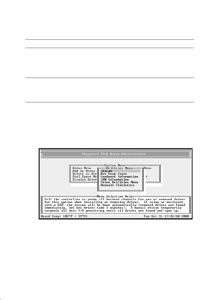
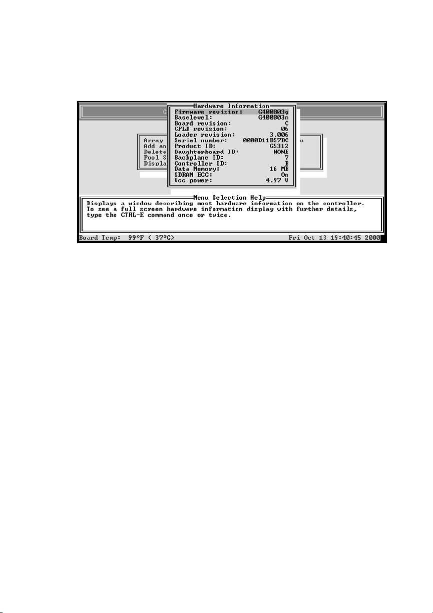
To display hardware information only:
From the System Menu, select Utilities Menu and press Enter.
1
The Utilities Menu screen displays.
5-8
Page 67
Monitoring System Status
Select Hardware Information and press Enter.
2
The Hardware Information screen displays.
Press Esc to return to the Utilities Menu.
3
5-9
Page 68
G- and K-Series User’s Guide
To display hardware and configuration information:
From anywhere in the Disk Array Administrator software, press CTRL-E.
1
The first screen of events from the event log displays.
Press CTRL-E again.
2
The Hardware Information screen displays.
Press CTRL-E again.
3
You can press Esc to return to the previous screen.
The Configuration Information screen displays.
Press CTRL-E or Esc to return to where you started from.
4
5-10
Page 69

Monitoring System Status
Displaying Overall Statistics
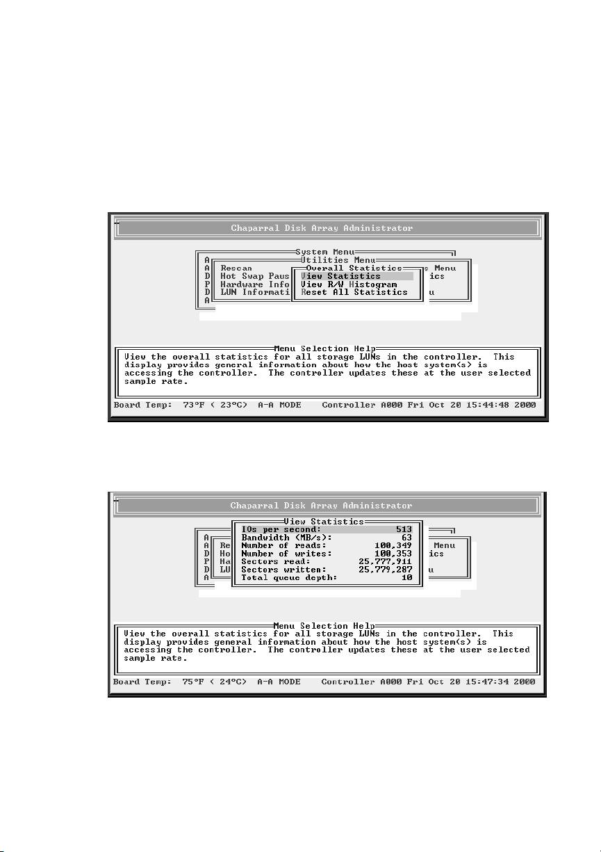
You can display two types of aggregate statistics for all array LUNs:
General statistics (Similar statistics are also available for individual array
!
LUNs. For more information, see
– I/O operations per second (IOPS)
– Bandwidth (in millions of bytes per second)
– Number of read operations
– Number of write operations
– Total sectors (512 byte) read
– Total sectors written
– Total current command queue depth across all LUNs
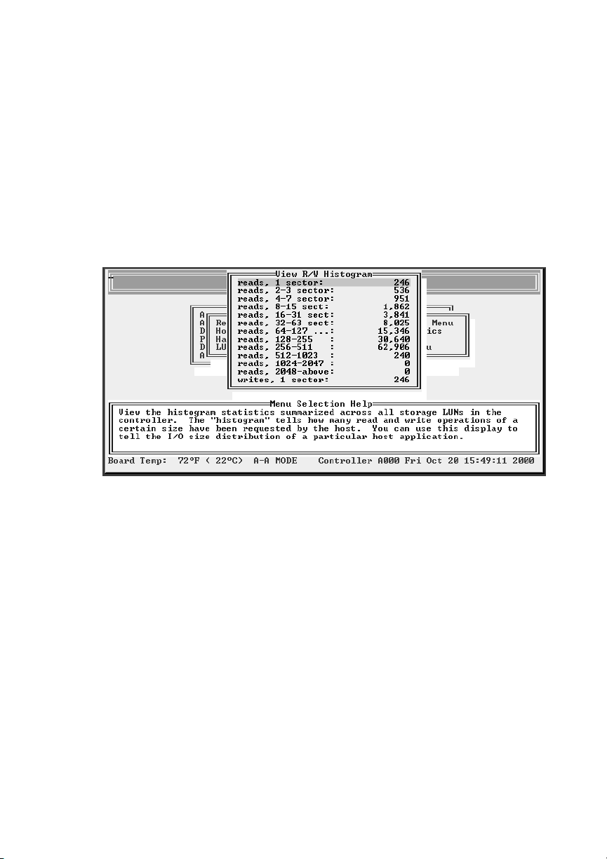
Host read/write histogram that shows how many host reads and writes fell into a
!
particular size range. The I/O ranges are based on powers of two:
– 1 Sector
– 2-3 Sectors
Viewing Array Statistics
on page 4-10.)
– 4-7 Sectors
– 8-15 Sectors
– 16-31 Sectors
– 32-63 Sectors
– 64-127 Sectors
– 128-255 Sectors
– 256-511 Sectors
– 512-1023 Sectors
– 1024-2047 Sectors
– 2048 (and larger) Sectors
This information may be helpful in interpreting performance based on individual
system configurations and operating systems. The information displayed here can be
useful to profile applications and their usage of the array and what type of RAID level
is applicable to your needs.
5-11
Page 70
G- and K-Series User’s Guide
To access the general array statistics:
From the System Menu, select Utilities Menu and press Enter.
1
The Utilities Menu screen displays.
Select Overall Statistics and press Enter.
2
The Overall Statistics screen displays.
Select View Statistics and press Enter.
3
The View Statistics screen displays.
Press Esc to return to the Overall Statistics screen.
4
5-12
Page 71
Monitoring System Status
To access the read/write histogram:
From the System Menu, select Utilities Menu and press Enter.
1
The Utilities Menu screen displays.
Select Overall Statistics and press Enter.
2
The Overall Statistics screen displays.
Select View R/W Histogram and press Enter.
3
The View R/W Histogram screen displays.
Press Esc to return to the Overall Statistics screen.
4
5-13
Page 72

G- and K-Series User’s Guide
Resetting Overall Statistics
You can also reset all of the overall statistics back to zero. You may want to reset the
statistics if you are monitoring performance or doing benchmark testing.
Note:
array. See
To reset overall statistics:
From the System Menu, select Utilities Menu and press Enter.
1
The Utilities Menu screen displays.
Select Overall Statistics and press Enter.
2
The Overall Statistics screen displays.
Select Reset All Statistics and press Enter.
3
The system confirms that you want to make the change.
Select Ye s and press Enter.
4
The system confirms that the statistics have been cleared and returns to the
Overall Statistics screen.
Resetting statistics here also resets the statistics for each individual
Viewing Array Statistics
on page 4-10.
❒
5-14
Page 73

6
Managing Spares
Chaparral RAID controllers automatically reconstruct redundant (fault-tolerant)
arrays (RAID 3, RAID 4, RAID 5, RAID 50, and mirrored) if an array becomes
critical and a properly sized spare drive is available. An array becomes critical when
one or more member drives fails.
You can set up two types of spare drives:
Dedicated—available drive that is assigned to a specific array. See page 6-1.
!
Pool—available drive that is assigned to the pool, which can provide a spare for
!
any failed drive in any redundant array. See page 6-5.
In addition, if you enable the Dynamic Spares option and a drive fails, you can
replace the drive and the controller will rescan the bus, find the new disk drive, and
automatically start reconstruction of the array. See page 6-3.
The controller looks for a dedicated spare first. If it does not find a properly sized
dedicated spare, it looks for a pool spare.
If a reconstruct does not start automatically, it means that no valid spares are
available. To start a reconstruct, you must:
Replace the failed drive, if no other drive is available.
1
Add the new drive or another available drive as a dedicated spare to the array or
2
as a pool spare.
Remember that any pool spares added might be used by any critical array, not
necessarily the array you want
Managing Dedicated Spares
Dedicated spares are unused disk drives that you assign as a spare to a specific array.
The disk must be as large as the smallest member of the array. You cannot use a
dedicated spare drive in an array or as a pool spare.
6-1
Page 74
G- and K-Series User’s Guide
While using a dedicated spare is the most secure way to provide spares for your
arrays, it is also expensive to keep an idle drive assigned to each array. An alternative
method is to assign one or more idle drives to the spare pool. See Managing the Spare
Pool on page 6-5.
Adding a Dedicated Spare
You assign dedicated spare drives to a specific array. If a member drive in the array
fails, the controller uses a dedicated spare drive to automatically reconstruct the array.
You can add dedicated spare drives to Mirrored (RAID 1 and RAID 10) and Parity
(RAID 3, RAID 4, RAID 5, and RAID 50) arrays when you create the array or
afterward. You can assign up to four dedicated spare drives to an array. For more
information about assigning spares when you create an array, see
page 4-1.
Creating Arrays
on
Note:
replace the smallest member in the array.
To add a dedicated spare:
From the System Menu, select Array Menu and press Enter.
1
The Select Array screen displays with a list of existing arrays.
Select the array you want and press Enter.
2
The Array Menu screen displays.
Select Add Spare and press Enter.
3
The list of drives screen displays listing the available drives.
Note:
you cannot use it as a spare until you clear the drive’s metadata. For more
information, see
Select the drive you want to add as a spare and press Enter.
4
The system confirms the change.
Select Ye s and press Enter.
5
A spare cannot be added that does not have enough capacity to
If a drive was a member of an array and was removed from the array,
Clearing Metadata from a Drive
on page 8-4.
6-2
Page 75

Managing Spares
Deleting a Dedicated Spare
You can delete a dedicated spare drive from an array at any time.
To delete a dedicated spare drive:
From the System Menu, select Array Menu and press Enter.
1
The Select Array screen displays with a list of existing arrays.
Select the array you want and press Enter.
2
The Array Menu screen displays.
Select Delete Spare and press Enter.
3
Select the spare drive you want to delete and press Enter.
4
The system confirms the deletion.
Select Ye s and press Enter to delete the spare.
5
The drive is now available for use in an array or as a spare.
Enabling Dynamic Spares
The Dynamic Spares option lets you use all of your disk drives in redundant arrays,
without assigning one as a spare. For example, if you enable Dynamic Spares and a
drive fails, you can replace the drive and the controller will rescan the bus, find the
new disk drive, and automatically start reconstruction of the array. The controller
automatically finds the new drive and reconstructs the array.
With Dynamic Spares enabled, if you have spares or available drives, the controller
first looks for a dedicated or spare pool drive for the reconstruction. If none is found,
it uses an available drive, which the controller automatically assigns as a spare and
starts reconstruction.
You must make sure that the new or available drive has enough capacity to replace the
smallest member in the array and does not contain metadata (see Clearing Metadata
from a Drive
on page 8-4).
Note:
(SEP) will decrease if an array becomes critical with this option enabled and
there are no available drives to start a reconstruct. To minimize the
performance impact, increase the rescan rate as described in the steps below.
Performance in systems without a SAF-TE Enclosure Processor
6-3
Page 76
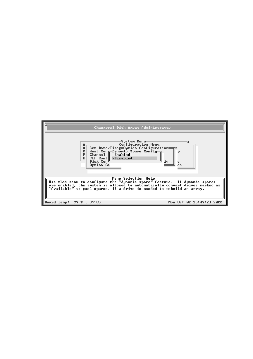
G- and K-Series User’s Guide
To enable dynamic spares:
From the System Menu, select Configuration Menu and press Enter.
1
The Configuration Menu screen displays.
Select Option Configuration and press Enter.
2
The Option Configuration screen displays.
Select Dynamic Spare Configuration and press Enter.
3
The Dynamic Spare Config screen displays. The current setting is marked with
an * next to it.
Select Enabled and press Enter.
4
The Rescan Rate screen displays.
Enter the rescan rate in minutes.
5
This tells the controller how often it should look for an available drive by
rescanning the bus. Remember that rescanning the bus frequently can affect
performance. If you have a SEP, the dynamic spare configuration will not
rescan the bus. The SEP will detect the new drive and tell the controller to
rescan and the rescan rate you set here will not affect the system.
The system confirms the change.
Select Ye s and press Enter.
6
6-4
Page 77
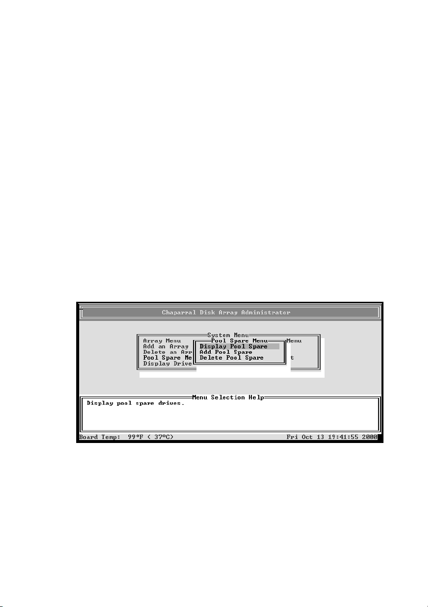
Managing Spares
Managing the Spare Pool
The spare pool lets you have one or more disk drives available for the reconstruction
of redundant arrays (Mirrored [RAID 1 and RAID 10] and Parity [RAID 3, RAID 4,
RAID 5, and RAID 50]) arrays. Once you assign a drive to the spare pool, it is not
available for use as an array member or as a dedicated spare.
If a pool spare is too small (smaller than an individual member in an array), the
controller cannot use it.
Adding a Spare to the Spare Pool
You can add up to eight drives to the spare pool to reconstruct any critical array on the
controller. After an array has started using a pool spare, other critical arrays are
prevented from using it. For a pool spare to be used, it must be at least as large as the
minimum drive size in the array.
To add a pool spare:
From the System Menu, select Pool Spare Menu and press Enter.
1
The Pool Spare Menu screen displays.
6-5
Page 78
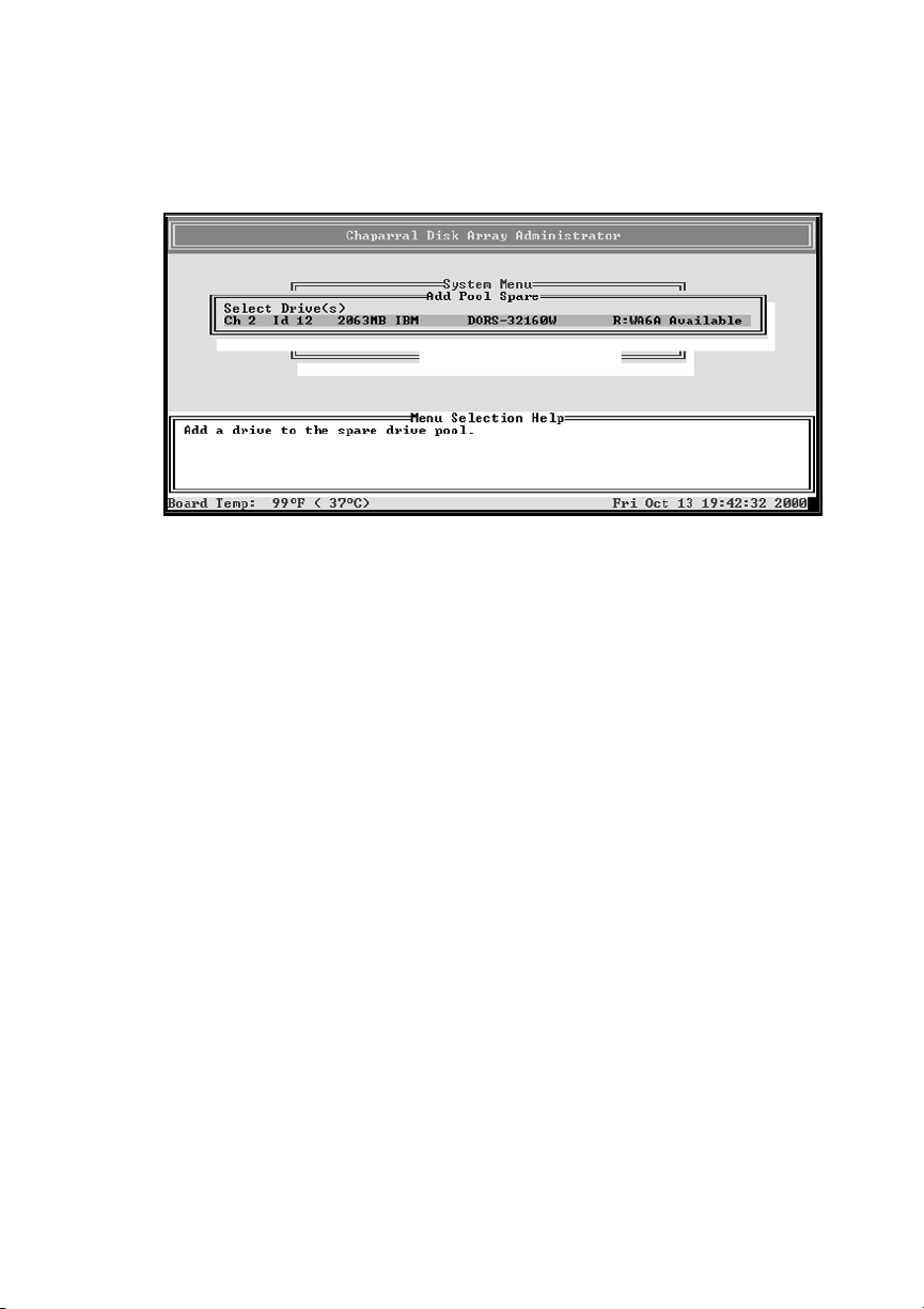
G- and K-Series User’s Guide
Select Add Pool Spare and press Enter.
2
The Select Drives screen displays.
Select each spare drive you want to add and press Enter.
3
Deleting a Spare from the Spare Pool
You can delete a spare from the spare pool at any time.
To delete a spare from the spare pool:
From the System Menu, select Pool Spare Menu and press Enter.
1
The Pool Spare Menu screen displays.
Select Delete Pool Spare and press Enter.
2
The Delete Pool Spare screen displays listing the drives assigned to spare pool.
Select the pool spare you want to delete and press Enter.
3
6-6
Page 79

Managing Spares
Displaying the Spare Pool
You can display a list of the all of the pool spares.
To display the spare pool:
From the System Menu, select Pool Spare Menu and press Enter.
1
The Pool Spare Menu screen displays.
Select Display Pool Spares and press Enter.
2
The Display Pool Spare screen displays listing all disk drives assigned to the
spare pool.
Press Esc to return to the Spare Pool Menu.
3
❒
6-7
Page 80

G- and K-Series User’s Guide
6-8
Page 81

7
Configuring the Controller
The Disk Array Administrator lets you configure settings and perform a variety of
functions on the controller. You can:
Reboot the controller (see page 7-1)
!
Change the date and time (see page 7-2)
!
Change the LUN and target ID or FC Loop ID (see page 7-4)
!
Configure the SCSI channels (see page 7-9)
!
Set up LUN zoning (see page 7-11)
!
Change the sample rate (see page 7-17)
!
Change the alarm mute setting (see page 7-18)
!
Lock the cache setting (see page 7-20)
!
Enable or disable the battery (see page 7-21)
!
Change the I/O priority (see page 7-22)
!
Rescan all channels (see page 7-23)
!
Pause I/O (see page 7-24)
!
Restore the default settings (see page 7-25)
!
Upgrade the firmware (see page 7-26)
!
Rebooting the Controller
You may need to shut down and restart the controller after making certain
configuration changes and when you move it or make hardware changes. We strongly
recommend that you shut down the controller gracefully and do not just turn off the
power. A normal shut down ensures that the write-back cache has been flushed to the
disk.
7-1
Page 82
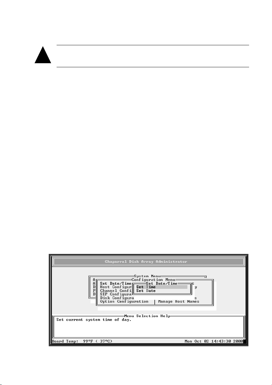
G- and K-Series User’s Guide
Caution:
will lose access and may lose data.
!
To shut down and restart the controller:
From the System Menu, select Shutdown/Restart and press Enter.
1
The system confirms that you want to shut down.
Select Ye s and press Enter.
2
The system confirms that it has shut down.
Press Enter to reboot.
3
The system performs its self-test. When you see the Disk Array Administrator
initial screen, the controller is ready. See Chapter 3,
Administrator Software.
Anyone accessing an array when you shut down the controller
Accessing the Disk Array
Changing the Date and Time
You can change the controller’s date and time.
To set the controller’s date:
From the System Menu, select Configuration Menu and press Enter.
1
The Configuration Menu screen displays.
Select Set Date/Time and press Enter.
2
The Set Date/Time screen displays.
7-2
Page 83
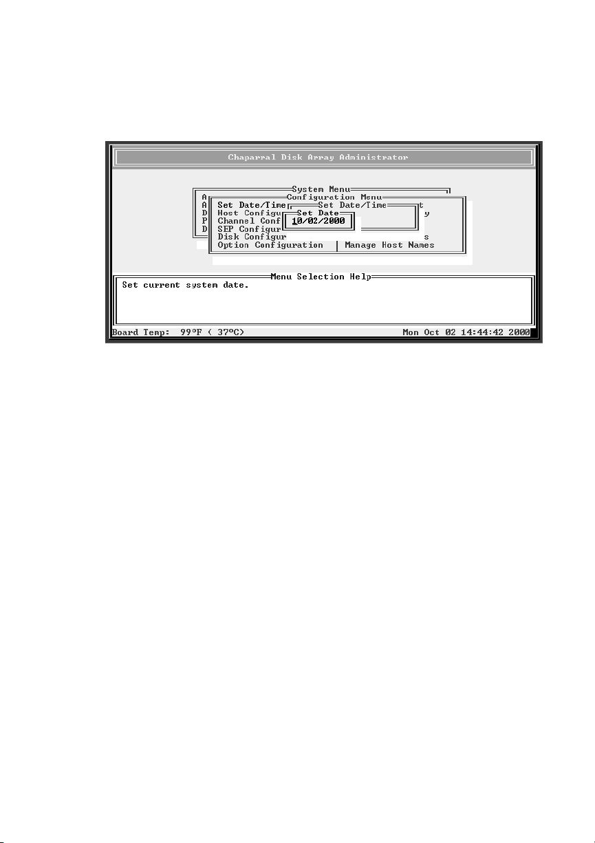
Configuring the Controller
Select Set Date and press Enter.
3
The Set Date screen displays.
Enter the date you want and press Enter.
4
Enter the date in the following format: MM/DD/YYYY.
The system confirms that you want to make the change.
Select Ye s and press Enter to make the changes.
5
The system confirms that the changes are made.
Press Esc to return to the Configuration Menu.
6
To set the controller’s time:
From the System Menu, select Configuration Menu and press Enter.
1
The Configuration Menu screen displays.
Select Set Date/Time and press Enter.
2
The Set Date/Time screen displays.
7-3
Page 84
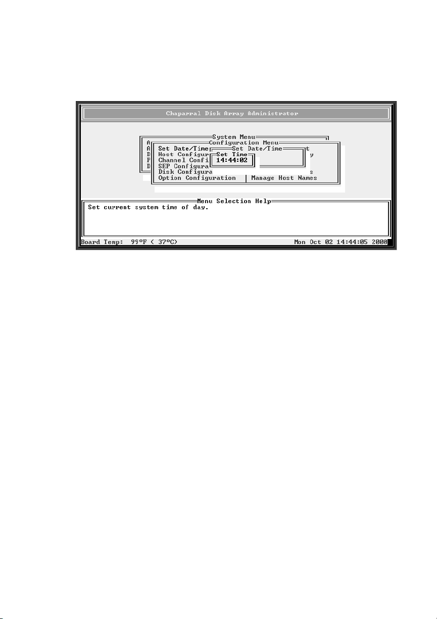
G- and K-Series User’s Guide
Select Set Time and press Enter.
3
The Set Time screen displays.
Enter the time you want and press Enter.
4
Enter the time in the following format: hh:mm:ss.
The system confirms that you want to make the change.
Select Ye s and press Enter to make the changes.
5
The system confirms that the changes are made.
Press Esc to return to the Configuration Menu.
6
Changing the Controller’s LUN and SCSI Target ID or Fibre Channel Loop ID
You can change the SCSI target ID or the Fibre Channel Loop ID and the LUN that
the controller uses on the host bus.
Understanding LUNs
The RAID controller supports up to eight SCSI Logical Unit Numbers (LUNs) that
are numbered zero through seven. There are three different types of LUNs: controller,
SEP, and Array. These LUNs have the following characteristics:
7-4
Page 85
Configuring the Controller
Controller LUN—You only need to assign a controller LUN if you are using the
!
Configuration Application Program Interface (CAPI) to configure the controller
over a host channel via SCSI protocol extensions. If you are not using CAPI,
you can set the controller LUN to NONE. If you are using CAPI, you can set it
to a value of 0-7 or SOFT. If set to SOFT, the controller LUN is automatically
assigned a LUN value when the controller boots. The soft LUN value will be
assigned to the first available LUN (starting from zero) that does not already
have a hard (that is, a numeric) LUN assignment.
Note:
Most Unix, Linux, and Macintosh operating systems require the
controller LUN to be a higher value than all array LUNs. Before creating
your first array, change the controller LUN to a higher value or choose
NONE (best choice) if you are not using CAPI to manage the arrays. This
allows your first array to be seen at LUN 0.
SEP LUNs—Allow access to SEPs. A SEP LUN may be set to a value of 0-7,
!
SOFT (see the controller LUN description for the meaning of SOFT), or NONE.
NONE means that the SEP cannot be accessed via a LUN. Note that if both a
controller LUN and a SEP LUN are set to SOFT, the controller LUN will be
assigned a value first. For information about changing the SEP LUN, see
Changing the SEP LUN
Array LUNs—Allow access to arrays on the controller. Array LUNs may be set
!
on page 8-12.
any numeric value from 0-7. They may not be set to a SOFT value. Note that an
array LUN value may be set to overlap a SOFT controller LUN value. In this
case, the controller will keep the numeric value of the overlapped LUN (and the
array will not be visible) until you reboot, after which the array will take the
LUN, and the controller LUN will change to first available SOFT LUN value.
For information about changing the array LUN, see
Changing the Array LUN
on page 4-21.
Note:
Because a maximum of eight LUNs are supported, if eight arrays are
required, the controller and SEP LUNs will not be accessible, and must be
set to SOFT or NONE.
7-5
Page 86

G- and K-Series User’s Guide
Changing the Controller’s Target ID and LUN
You can change the controller’s target ID or LUN, if necessary:
Target ID—This is either the SCSI target ID for the G5312 or K5312 or the
!
controller’s FC Loop ID for the G7313 or K7313.
– SCSI target ID—You may need to change controller’s SCSI target ID when
you have existing devices at ID 1, the controller’s default, or when you are
adding more than one controller to a system.You can set the target ID to any
number between 0 and 15.
– FC Loop ID—You may need to change this if you want the controller to be
at a specific address or if your system checks addresses in reverse order
(lowest address first). You have two options:
SOFT—Use this setting if you do not care if the controller’s Loop ID
changes when you power down and power up. This setting lets the FC loop
initialization process determine the Loop ID.
Any number between 0 and 125—Select a specific number if you want the
Loop ID to stay the same after you power down and power up. The Disk
Array Administrator software cannot tell you which Loop IDs are available.
To be sure that you have successfully assigned the Loop ID you want, check
the Loop ID after you reboot the controller. If the controller cannot get the
specified Loop ID during the loop initialization process, it will try to get a
soft address.
LUN—You only need to assign a controller LUN if you are using the
!
Configuration Application Program Interface (CAPI) to configure the controller
over a host channel via SCSI protocol extensions.
If you are not using CAPI, you can set the controller LUN to NONE. If you are
using CAPI, you can set it to a value of 0-7 or SOFT. If set to SOFT, the
controller LUN is automatically assigned a LUN value when the controller
boots. The soft LUN value will be assigned to the first available LUN (starting
from zero) that does not already have a hard (that is, a numeric) LUN
assignment.
You can have three options for setting the LUN:
– NONE—Use this setting if you are not using CAPI to configure the
controller (this change takes effect immediately).
– SOFT—Use this setting if you do not care if the controller’s LUN changes
when you reboot the controller.
7-6
Page 87
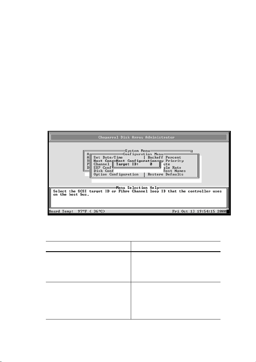
Configuring the Controller
– Any number between 0 and 7—Select a specific number if you want the
controller’s LUN to stay the same when you reboot.
To change the controller’s target ID and LUN:
From the System Menu, select Configuration Menu and press Enter.
1
The Configuration Menu screen displays.
Select Host Configuration and press Enter.
2
The Host Configuration screen displays.
Select Target ID and press Enter.
3
The Target ID screen displays.
Select the option or number you want to use and press Enter.
4
To Do this
Set a SCSI Target ID
FC Loop ID
Let the FC loop initialization
process determine the Loop ID for
the channel each time the
controller powers up
! Select the [target ID] you want to
use and press Enter.
This can be any number from 0 to
15.
!
Select SOFT and press Enter.
This is the default setting.
7-7
Page 88
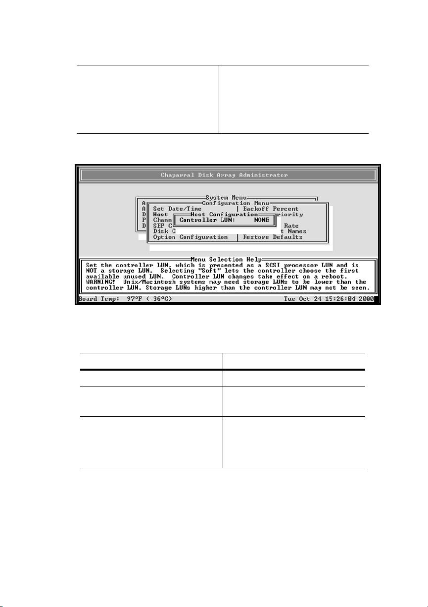
G- and K-Series User’s Guide
To Do this
Keep the same Loop ID for the
channel at all times
! Select the [Loop ID] you want to
use and press Enter.
This can be any number from 0 to
125.
The Controller LUN screen displays.
Select the option or number you want to use.
5
To Do t h is
Not assign the controller a LUN
Let the controller determine the
channel LUN each time it powers up
Keep the same LUN for the
controller at all times
! Select NONE and press Enter.
! Select SOFT and press Enter.
This is the default setting.
! Select the [LUN] you want to use
and press Enter.
This can be any number from 0 to
7.
The system confirms that you want to make the change.
Select Ye s and press Enter to make the changes.
6
7-8
Page 89
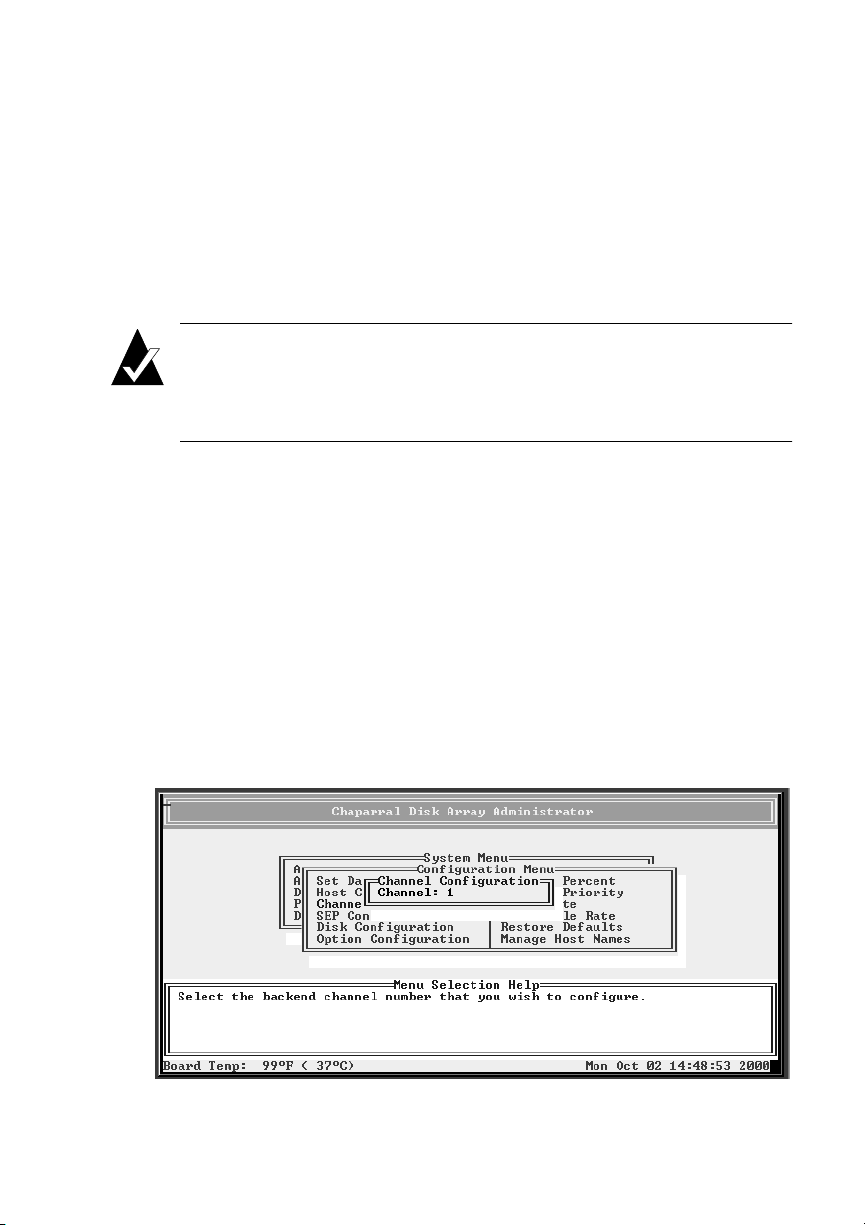
Configuring the Controller
Configuring the SCSI Channels
You can change two channel configuration options for each channel:
Channel speed—You can change the channel speed for each SCSI channel on
!
the controller. You can select Ultra or Ultra2. This is helpful if you are
troubleshooting a problem on the channel or if you have legacy ultrawide disk
drives.
Note:
ended bus, transfer rates are 40 MB/sec maximum; for an LVD bus, 80
MB/sec maximum. This Ultra SCSI setting only affects the device channel.
Host SCSI channel rates are controlled by setting the host adapter.
SCSI ID assigned to each channel (initiator ID)—The controller assigns each of
!
its SCSI channels one of the SCSI IDs (initiator IDs), leaving 15 SCSI IDs
available for devices. You can change the SCSI ID assigned to each channel.
You may need to do this if the default ID, 7, conflicts with a SEP ID. You can
set the ID to any number between 0 and 15.
To configure the channel:
From the System Menu, select Configuration Menu and press Enter.
1
The Configuration Menu screen displays.
Select Channel Configuration and press Enter.
2
The Channel Configuration screen displays.
Ultra/Ultra2 SCSI is enabled by default. This means that for a single-
7-9
Page 90
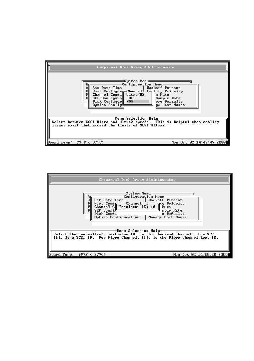
G- and K-Series User’s Guide
Select the channel you want and press Enter.
3
The Ultra/U2 screen displays.The current setting is marked with an * next to it
Select the setting you want and press Enter.
4
The initiator ID screen displays showing the current initiator ID.
Select the initiator ID you want and press Enter.
5
The system confirms that you want to make the change.
Select Ye s and press Enter to make the changes.
6
Press Esc to return to the Configuration Menu.
7
7-10
Page 91
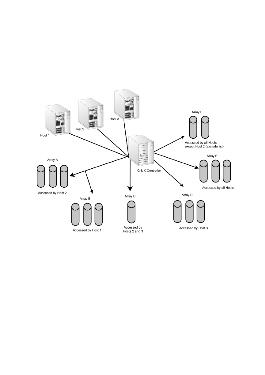
Configuring the Controller
Working with LUN Zoning
The controller’s LUN zoning capability lets you specify which servers (hosts) can
access each array. This gives you complete control of array access based on your
specific needs. LUN zoning is only available on the G7313 and K7313 models.
Figure 7-1 shows an example of how you can use LUN zoning.
Figure 7-1. LUN zoning example
Before you set up LUN zoning, you should know the World Wide Name (WWN) for
each server that you want to set up. Your SAN administrator should know the WWNs
for your network. You can display a list of all WWNs that the controller is aware of
on the SAN, and you can give each WWN a name (alias) of your own. This makes
working with the LUN zoning feature faster and easier.
You set up LUN zoning by either excluding or including servers on a list for each
array LUN. The list can include or exclude up to 16 specific servers or all servers for
each array LUN.
For example, in Figure 7-1, Array A has an include list that only contains Host 2, so
only Host 2 can access Array A. Array F has an exclude list that contains only Host 2,
so all hosts
for Host 2 can access the array.
except
7-11
Page 92
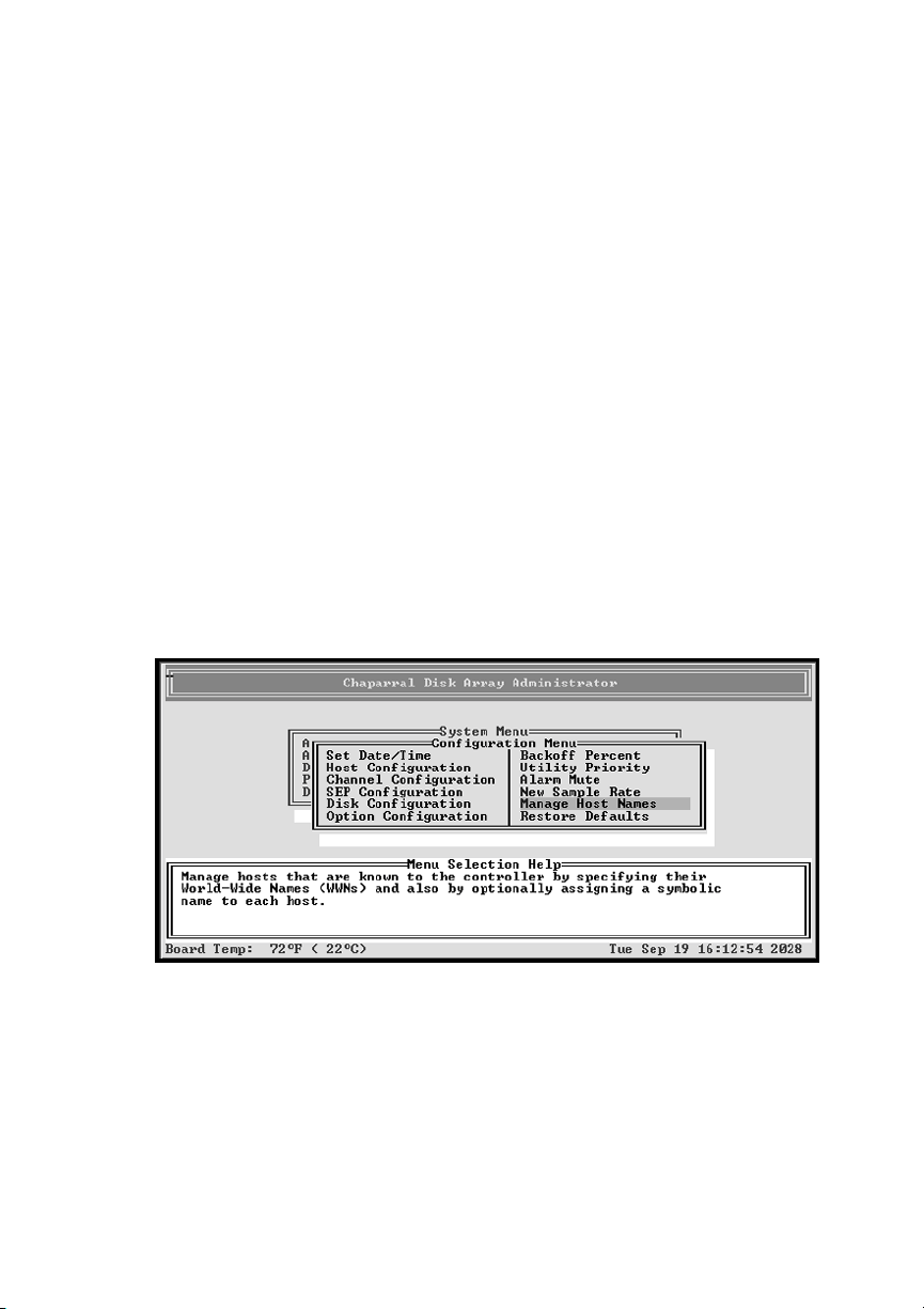
G- and K-Series User’s Guide
Viewing Known WWNs
You can view a list of all server (host) WWNs that the controller is aware of on your
SAN. The controller will be aware of any server that was booted since the controller
was last restarted. Typically, servers scan for devices during their device discovery
process. When this happens, the controller saves the WWN information for the server
and retains the information even after you reboot the controller.
You can determine which WWN is for which server by booting one server at a time
and then viewing the WWN list. The most recently booted server is first on the list.
You can then give the servers names you recognize, for example you can use the
computer name that has already been assigned to each server, to make LUN zoning
easier to manage.
To view known WWNs:
From the System Menu, select Configuration Menu and press Enter.
1
The Configuration Menu screen displays.
Select Manage Host Names and press Enter.
2
The Manage Host Names screen displays.
7-12
Page 93
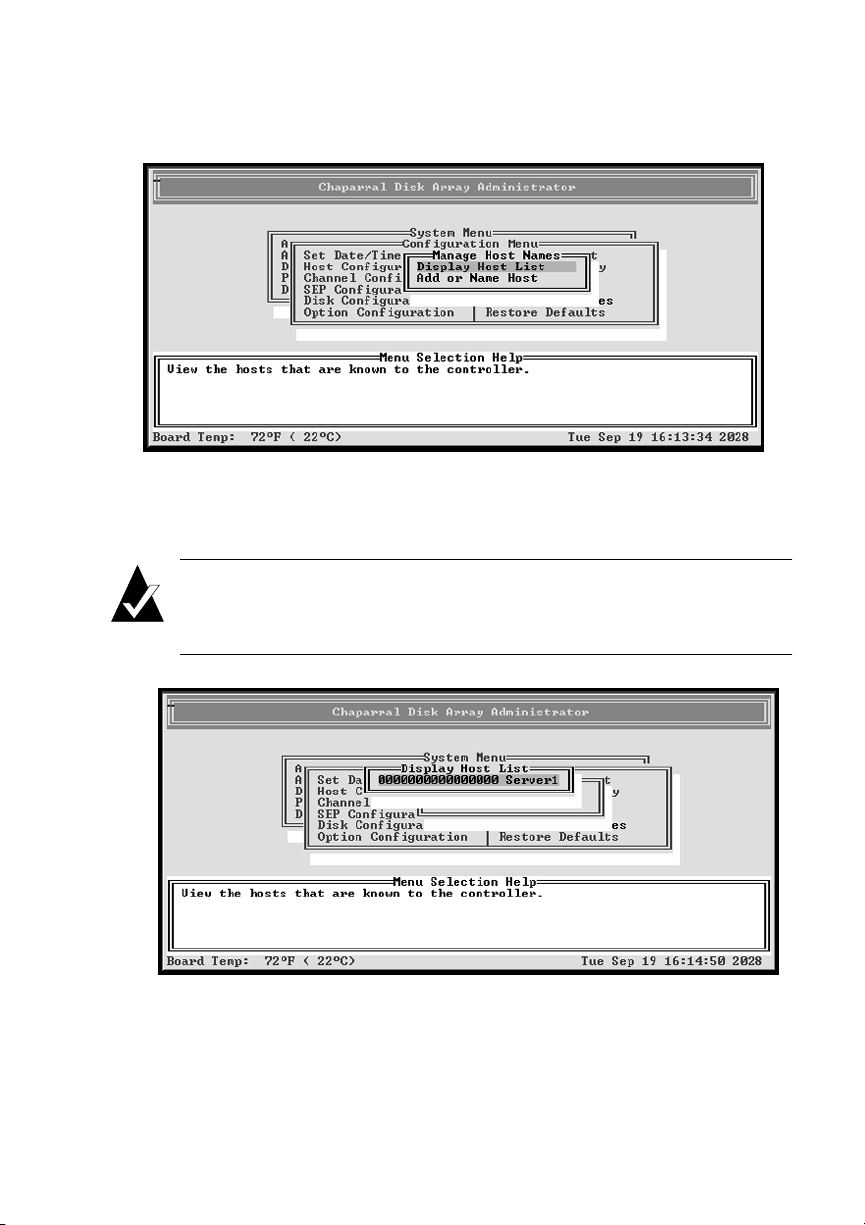
Configuring the Controller
Select Display Host List and press Enter.
3
The Display Host List screen displays showing all WWNs known to the
controller. The WWNs are listed according the when they were booted. The
most recently booted server (host) is listed first
Note:
whenever the host performs a device discovery or bus scanning type of
operation.
Press Esc to return to the Manage Host Names screen.
4
A hosts WWN can be placed at the top of the known hosts list
7-13
Page 94
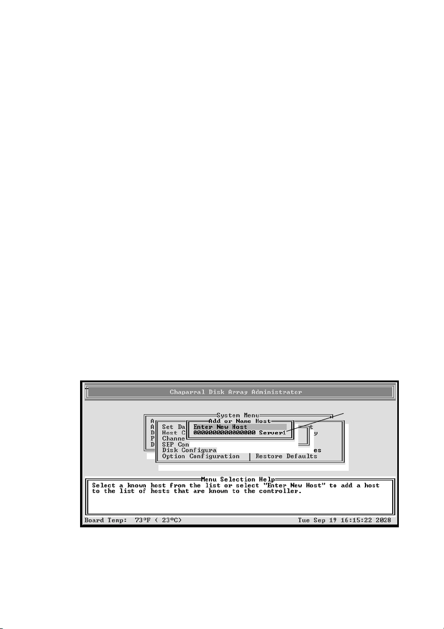
G- and K-Series User’s Guide
Creating Names (Aliases) for Server WWNs
You can give the servers on your SAN names (aliases) that you can easily recognize
to make LUN zoning easier to manage. For example, you can use the computer name
that has already been assigned to each server.
You can determine which WWN is for which server by booting one server at a time
and then viewing the WWN list. The most recently booted server is first on the list.
You can name up to 63 servers. The names are stored on the controller, so if you
change controllers, you have to rename the servers.
To create or change names for WWNs:
From the System Menu, select Configuration Menu and press Enter.
1
The Configuration Menu screen displays.
Select Manage Host Names and press Enter.
2
The Manage Host Names screen displays.
Select Add or Name Host and press Enter.
3
The Add or Name Host screen displays all known WWNs and host names that
you have set up. If you want to change the name (alias), enter the new name in
Step 5. For more information see
Viewing Known WWNs
on page 7-12.
If the controller is not aware of any WWNs, the list is empty. Select Enter New
Host to enter a WWN.
Name set up
previously
7-14
Page 95
Configuring the Controller
Note:
will attempt to give the WWN a default name. The default name, if
available, is the name of the manufacturer of the server’s host bus adapter
(HBA), enclosed in angle brackets. For example, a Qlogic HBA will have a
default name of <Qlogic>.
Select the WWN you want to name and press Enter.
4
The Enter Host Name screen displays.
Enter the name (alias) you want and press Enter.
5
You can enter up to 16 characters. You can use any combination of characters
and spaces.
If you have not manually assigned a WWN an alias, the controller
Configuring LUN Zoning
Once you set up server (host) names (aliases), you can easily set up your LUN zoning.
This is where you determine which servers can access each array LUN.
You set up LUN zoning by either excluding or including servers on a list for each
array LUN. The list can include or exclude up to 16 specific servers or all servers for
each array LUN.
The zoning information is stored as part of the array’s metadata using the WWN for
each server. If you install a new controller, the array’s LUN zoning will remain. The
LUN zoning will also remain if you change the array’s LUN.
Note:
should make changes that limit access to arrays when the arrays are not in
use.
To set up LUN zoning:
From the System Menu, select Array Menu and press Enter.
1
The Select Array screen displays with a list of existing arrays.
Select the array you want and press Enter.
2
The Array Menu screen displays.
Changes to LUN zoning take effect immediately, therefore, you
7-15
Page 96
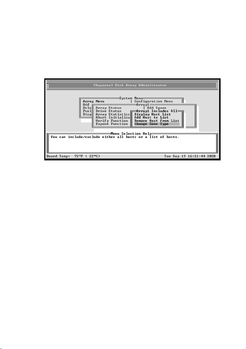
G- and K-Series User’s Guide
Select LUN Zoning and press Enter.
3
The LUN Exclude List or LUN Include List screen displays. The default setting
for each array LUN is Include All Hosts. This results in all servers (hosts) being
able to access all arrays. You can change the list type using the Change Zone
Type option. See the next step.
Select the option you want and press Enter.
4
– Display Host List—Displays a list of the servers (hosts) currently on the
include or exclude list for the selected array. This option only displays
servers if you have already used Add Host to List and added one or more
WWNs to an include or exclude list.
– Add Host to List—Displays the Enter Host WWN screen where you enter
the WWN or name (alias) or select the server you want to add to the current
list for the selected array. Enter the WWN or name (alias) or select the server
from the list and press Enter.
– Remove Host from List—Displays the Remove Host from List screen
which contains a list of the servers (hosts) currently on the include or
exclude list for the selected array. Select the WWN of the server you want to
remove from the list and press Enter.
– Change Zone Type—Displays the Change Zone type screen where you can
change the type of zoning to one of four options described below. Changing
the zone type does not add or remove any hosts in previously created lists.
7-16
Page 97

Configuring the Controller
Include All Hosts—Permits all servers (hosts) on the network to access the
selected array. This is the default zone type. This results in all servers (hosts)
being able to access all arrays. If you have already created an include or
exclude list, you can use this option to override the list. Your existing list is
retained and you can display, add, or remove servers from the list.
Include Listed Hosts—Lets you enter or select the WWNs of the specific
servers (hosts) you want to be able to access the selected array.
Exclude All Hosts—Permits no servers (hosts) on the network to access the
selected array. If you have already created an include or exclude list, you can
use this option to override the list. Your existing list is retained and you can
display, add, or remove servers from the list.
Exclude Listed Hosts—Lets you enter or select the WWNs or names
(aliases) of the specific servers (hosts) you do not want to be able to access
the selected array.
Whether you use an include or exclude list depends on your needs. You may
want to determine which list would be shorter and create the shorter list.
If you have changed the LUN zoning, the system confirms that you want to
make the change.
Select Ye s and press Enter to make the changes.
5
The system confirms that the changes are made.
Press Esc to return to the LUN Zoning screen.
6
Changing the Sample Rate
You can set how often the controller samples data when updating status screens (disk
and array). The default is one second.
To change the sample rate:
From the System Menu, select Configuration Menu and press Enter.
1
The Configuration Menu screen displays.
Select New Sample Rate and press Enter.
2
The New Sample Rate screen displays.
Enter the sample rate and press Enter.
3
7-17
Page 98

G- and K-Series User’s Guide
Changing the Alarm Mute Setting
You can enable or disable the audible alarm that sounds when the controller becomes
too hot, detects low or high voltage, or an array becomes critical or offline. Changing
the mute setting lets you turn off the alarm when it is sounding. You should turn it
back on after resolving the problem.
The alarm sounds for temperature or voltage conditions (events). Warning events are
generated when the temperature or voltage enters the warning range. Shutdown
events are generated when the temperature or voltage enters the shutdown range.
After reaching the shutdown range, the controller will not function. You must resolve
the problem and reboot the controller. If the problem is not resolved, it will shut down
again.
Alarm conditions trigger an event message that displays in the Disk Array
Administrator software window and in the event log. See Displaying the Event Log
on page 5-1.
Table 7-1 shows the temperature and voltage thresholds for each alarm and what to
do to resolve the problem.
Table 7-1. Alarm thresholds
Alarm threshold What to do when the alarm sounds
CPU temperature
Warning—0°C to 5°C and
65°C to 70°C
Shutdown—0°C and 70°C
<0°C and >70°C
Onboard temperature
Warning—0°C to 5°C and
45°C to 50°C
Shutdown—0°C and 50°C
<0°C and 50°C
7-18
! Check the
confirm what the alarm means. See Chapter 3,
Accessing the Disk Array Administrator
Software
! Check the ambient temperature and lower it, if
needed. Ambient temperature should be less
than 45°C.
! Same as above for the CPU temperature.
Disk Array
.
Administrator software to
Page 99
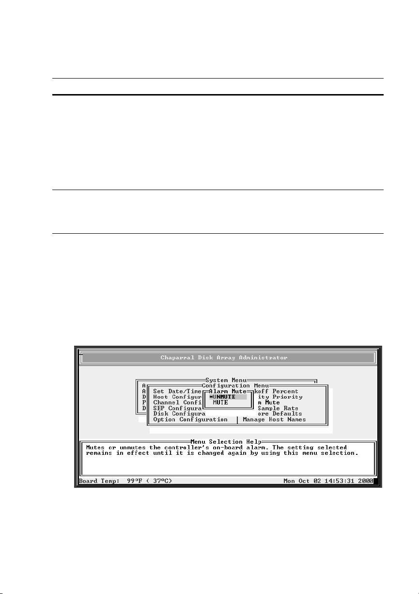
Configuring the Controller
Table 7-1. Alarm thresholds
Alarm threshold What to do when the alarm sounds
VCC voltage
Warning—5V -3.5% and +6.5%
Shutdown—5V -6.5% and +10%
! Check the
confirm what the alarm means. See Chapter 3,
Accessing the Disk Array Administrator
Software.
! If it is a warning alarm, let the controller
continue to operate.
! If it is a shutdown alarm, turn off the power to
the controller and send it for service.
Disk Array
Administrator software to
12V voltage
Warning—12V -8% and +8%
Shutdown—12V -10% and +10%
! Same as above for the VCC voltage.
To enable or disable the alarm:
From the System Menu, select Configuration Menu and press Enter.
1
The Configuration Menu screen displays.
Select Alarm Mute and press Enter.
2
The Alarm Mute screen displays. The current setting is marked with an * next
to it.
Select the option you want and press Enter.
3
7-19
Page 100
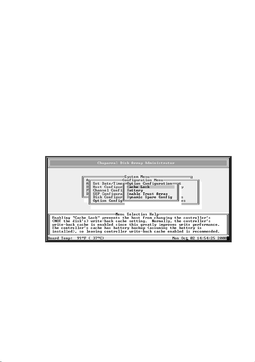
G- and K-Series User’s Guide
Locking the Cache Setting
You can prevent host systems from using SCSI mode select commands to change the
controller’s write-back cache setting. Some operating systems disable write cache. If
cache lock is enabled, the host cannot modify the cache setting. The default setting is
disabled.
This option is useful in some environments where the host system disables the
controller’s write-back cache, resulting in degraded performance.
To lock the cache setting:
From the System Menu, select Configuration Menu and press Enter.
1
The Configuration Menu screen displays.
Select Option Configuration and press Enter.
2
The Option Configuration screen displays.
7-20
 Loading...