


CHANNEL SAFETY SYSTEMS t: 0845 884 7000 | w: www.channelsafety.co.uk
Disabled persons toilet alarm kit
from Channel Safety Systems
CHANNEL SAFETY SYSTEMS t: 0845 884 7000
Peters eld Business Park f: 0845 884 6000
Bedford Road
Peters eld
Hampshire e: sales@channelsafety.co.uk
GU32 3QA w: www.channelsafety.co.uk
INSTRUCTION MANUAL - Issue 1 - 02/2014 | 1
INSTRUCTION MANUAL

CHANNEL SAFETY SYSTEMS t: 0845 884 7000 | w: www.channelsafety.co.uk
1st Ring to be 100mm from oor.
2
nd
Ring to be between 800/1000mm from oor.
Ceiling Pull Cord 3 Core 4 Core
230v AC
PSU & Lamp/Sounder
Reset/Sounder
to be 1200mm
max above oor.
DISABLED PERSONS TOILET ALARM KIT
The Help Alarm Response Kit meets the growing requirements for a means of indicating that assistance is required.
The Help Alarm Response Kit provides a simple solution to many such environments, these include:
• Disabled persons facilities
• Medical facilities
• Reception areas
• Lone workers
• Gym & spa
• Educational facilities
Equipment positioning within disabled persons facilities.
Approved Document M- ‘Access to & use of Buildings’
states the following:
…Pull cords for emergency alarms…are coloured red,
located as close to a wall as possible, and have two
red 50mm bangles, one set 100mm and the otherset
between 800 & 1000mm above the oor.
These should be reachable from the WC.
…Simple push buttons (reset unit) are notset more
than 1200mm above the oor. This should be
reachable from the WC.
…The emergency assistance signal (Lamp/sounder)
is located so thatit can be easily seen & heard by
those able to give assistance.
Additional options
The Help Alarm Response Kit can be linked to a remote multi-way indicator panel (for use in a reception orsta ed area).
Our reference is CH/HKI/2-2 way, through to CH/HKI/11-11 way.
A 12 volt relay unit(S/E60/A) can be used to interface the unit to a wide range of equipment such as:-
• BMS
• Fire alarms
• Intruder Alarms
• Paging transmitters
Additional pull cord units can be added to the system to allow for larger rooms or multi area coverage.
Please note that additional pull cords will operate & be reset by the same unit as the initial pull cord
INSTRUCTION MANUAL - Issue 1 - 02/2014 | 2
CHANNEL SAFETY SYSTEMS t: 0845 884 7000 | w: www.channelsafety.co.uk
DISABLED PERSONS TOILET ALARM KIT
Installation
Installation of this equipment must be carried out by a competent electrician to the requirements of the current IEE wiring regulations.
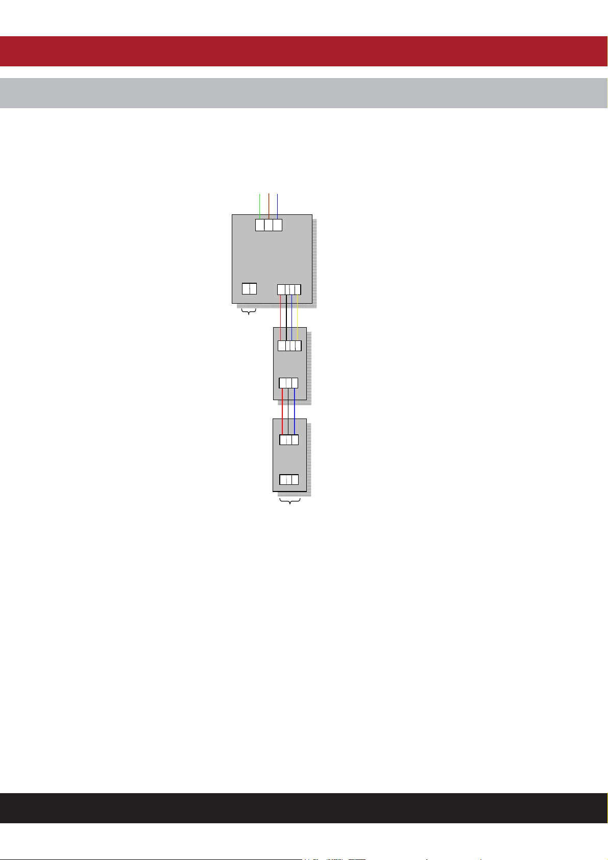
Connection details
230v AC
E L N
Power Supply incorporating
Lamp/Sounder
and battery back-up
12v 0v
To additional equipment
Including
CH/HKI Multi-way
indicator
12v 0v X1 X2
12v 0v X1 X2
RESET
UNIT
12v 0v X1
12v 0v X1
PULL
CORD
UNIT
12v 0v X1
Use ‘intruder
alarm’ type
stranded cable for
interlink wiring.
DO NOT USE
‘TWIN & EARTH’
or other rigid cable
types!
To next pull cord
Operation
Once the pull cord(s) are activated the reassurance LED on the pull cord will illuminate, the reset unit will illuminate & operate its internal sounder, and the
external lamp/sounder unit will operate along with any optional equipment installed.
Simply pressing the illuminated reset switch will return the system to the ‘normal’ State.
Battery details
A23 12V Alkaline Battery 10.3mm (D) x 28.5mm (L)
INSTRUCTION MANUAL - Issue 1 - 02/2014 | 3

CHANNEL SAFETY SYSTEMS t: 0845 884 7000
Peters eld Business Park f: 0845 884 6000
Bedford Road
Peters eld
Hampshire e: sales@channelsafety.co.uk
GU32 3QA w: www.channelsafety.co.uk
INSTRUCTION MANUAL
 Loading...