

Page 1
CHANNEL SAFETY SYSTEMS t: 0845 884 7000 | w: www.channelsafety.co.uk
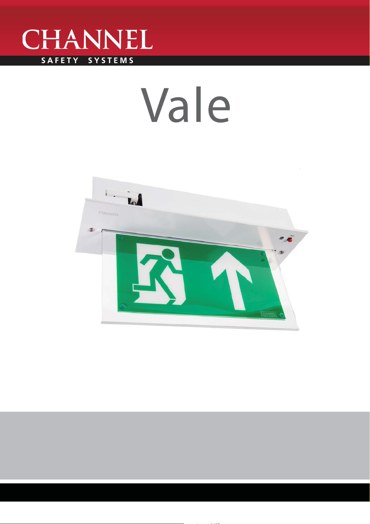
LED emergency exit signage
from Channel Safety Systems
CHANNEL SAFETY SYSTEMS t: 0845 884 7000
Peters eld Business Park f: 0845 884 6000
Bedford Road
Peters eld
Hampshire e: [email protected]
GU32 3QA w: www.channelsafety.co.uk
INSTRUCTION MANUAL - Issue 1 - 02/2014 | 1
INSTRUCTION MANUAL
Page 2
CHANNEL SAFETY SYSTEMS t: 0845 884 7000 | w: www.channelsafety.co.uk
INSTALLATION
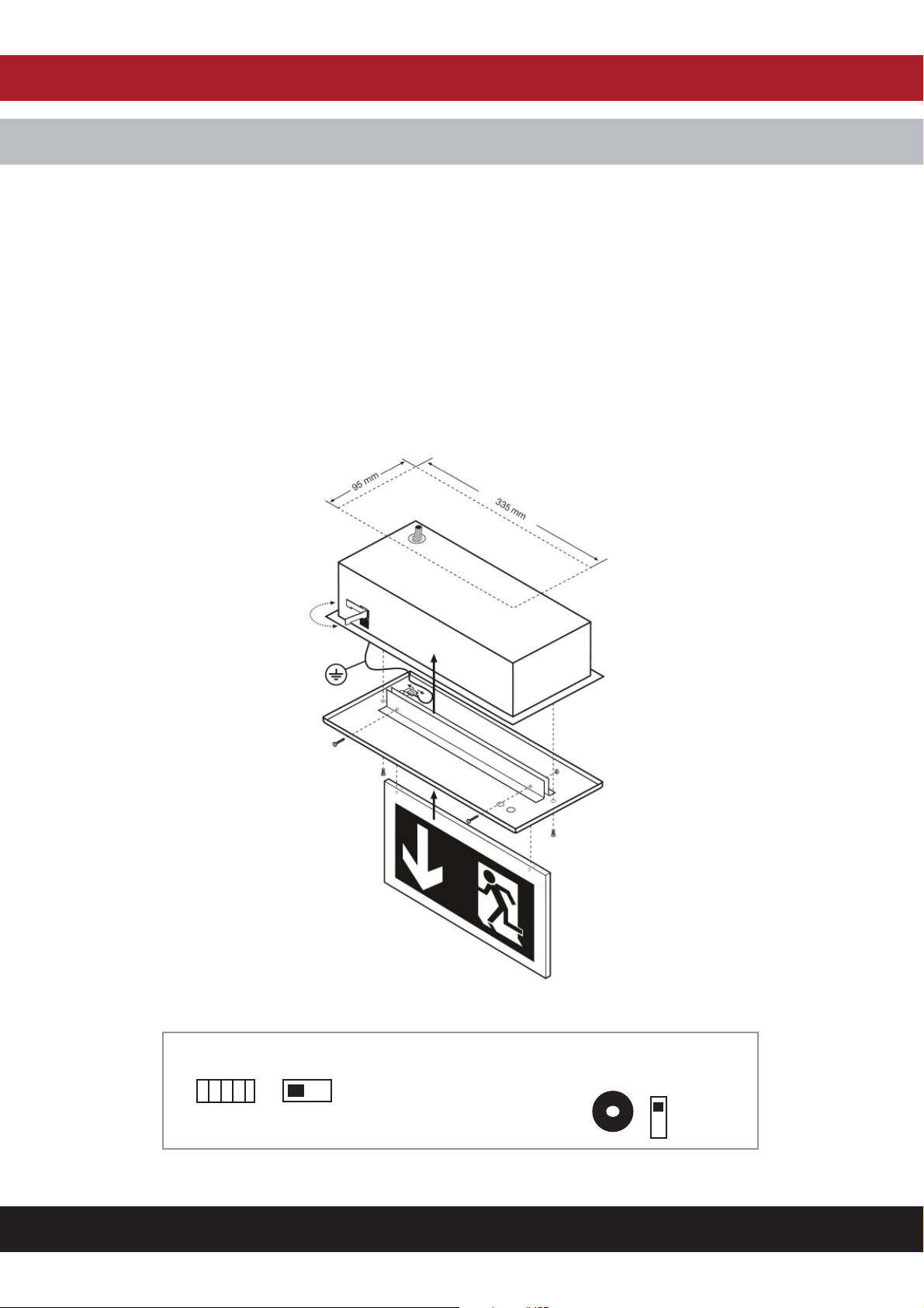
1. Remove the di user from the body by unscrewing the two retaining screws.
2. Fix base ceiling, cut out required 95mm x 335mm. Minimum height clearance 55mm
3. ISOLATE THE A.C. SUPPLY and connect unit. An unswitched 230V A.C.10% supply must be connected to the local permanent live (L). Earth and neutral
(N) terminals on the PCB block. When Maintained operation is required, illumination can be achieved by switching the selection switch to the
appropriate position.
4. The battery is pre-connected.
5. Fit the ‘legend blade’ Re t the & on the Wilmington the white end cap.
6. Operational Check – Restore the A.C. Supply for 30 minutes and then remove. The LEDs should illuminate for at least 10 seconds.
7. Restore the A.C. supply and check that the indicator LED is ‘on’.
8. A method of testing the luminaire should be incorporated in the supply circuit. This should be installed to fail the un-switched supply. A key switch may
be suitable (EN 60598-2-22:1998 22.20.1)
PCB layout
Input terminals Buzzer Switch
E E E L N
Maintained or Non- Maintained
On
O
INSTRUCTION MANUAL - Issue 1 - 02/2014 | 2
Page 3

CHANNEL SAFETY SYSTEMS t: 0845 884 7000 | w: www.channelsafety.co.uk
OPERATION
Maintained Or Non-Maintained Operation
The mode of operation can be chosen using the selection switch. This gives either maintained (LED’s always on) or non-maintained operation (LED’s o until a
power failure).
Buzzer
The fault buzzer may be switched on or o using the buzzer selection switch.
Monitoring
Green indicator lamp (LED) normally continuously ‘on’. Indicator lamp goes out if A.C. Supply or charger fails.
Battery
Sealed Nickel-Cadmium rechargeable battery pack.
Temperature
Performance gures measured at 25C.
Fault Finding And Corrective Action
Monitoring Led Not Illuminated
A.C. Supply not healthy. Battery not connected. Charger failed.
Unit Not Meeting Required Emergency Period
May need cycling: Discharge then recharge for 24 hours. Re-test, Battery pack may need replacing if emergency duration still not met.
Environmental Parameters
Rated performance limits:
Temperature Min 5C - Max 25C
Humidity 80% max
INSTRUCTION MANUAL - Issue 1 - 02/2014 | 3
Page 4
CHANNEL SAFETY SYSTEMS t: 0845 884 7000 | w: www.channelsafety.co.uk
TESTING
Recommended Routine Test Procedure
The unit is designed to carry out self testing in accordance with (EN 62034:2006 3.6), (EN 62034:2006 3.7) & (EN 62034:2006 5.1).
The following test is designed to ensure the continued protection of your premises and occupants. Because of the possibility of a failure of the normal
lighting supply occurring shortly after a period of testing, all tests should, whenever possible, be undertaken at times of least risk, e.g. during daylight hours.
Once A Day
Visual inspection of battery charge led.
Once A Month
Each unit should be energised from it’s battery for adequate time to ensure, by simulation of a failure of the normal lighting supply, the emergency mode is
functioning correctly.
Once Each Year
All units should be placed into emergency mode and checked that the duration provided by the battery meets the speci ed time period.
Forest ‘Self-Test’
• 20 hours after applying mains voltage a function test is automatically run (30 sec. The items checked are ‘emergency changeover and lamp.
• After a further 4 hours, an automatic 3 hour duration test is run. (If the test button is pressed for 5 sec. before the duration test has ended, the test is
aborted.)
• Following the rst duration test, regardless of whether or not this was passed, the weekly function test and yearly duration test are automatically started.
Manual Operation
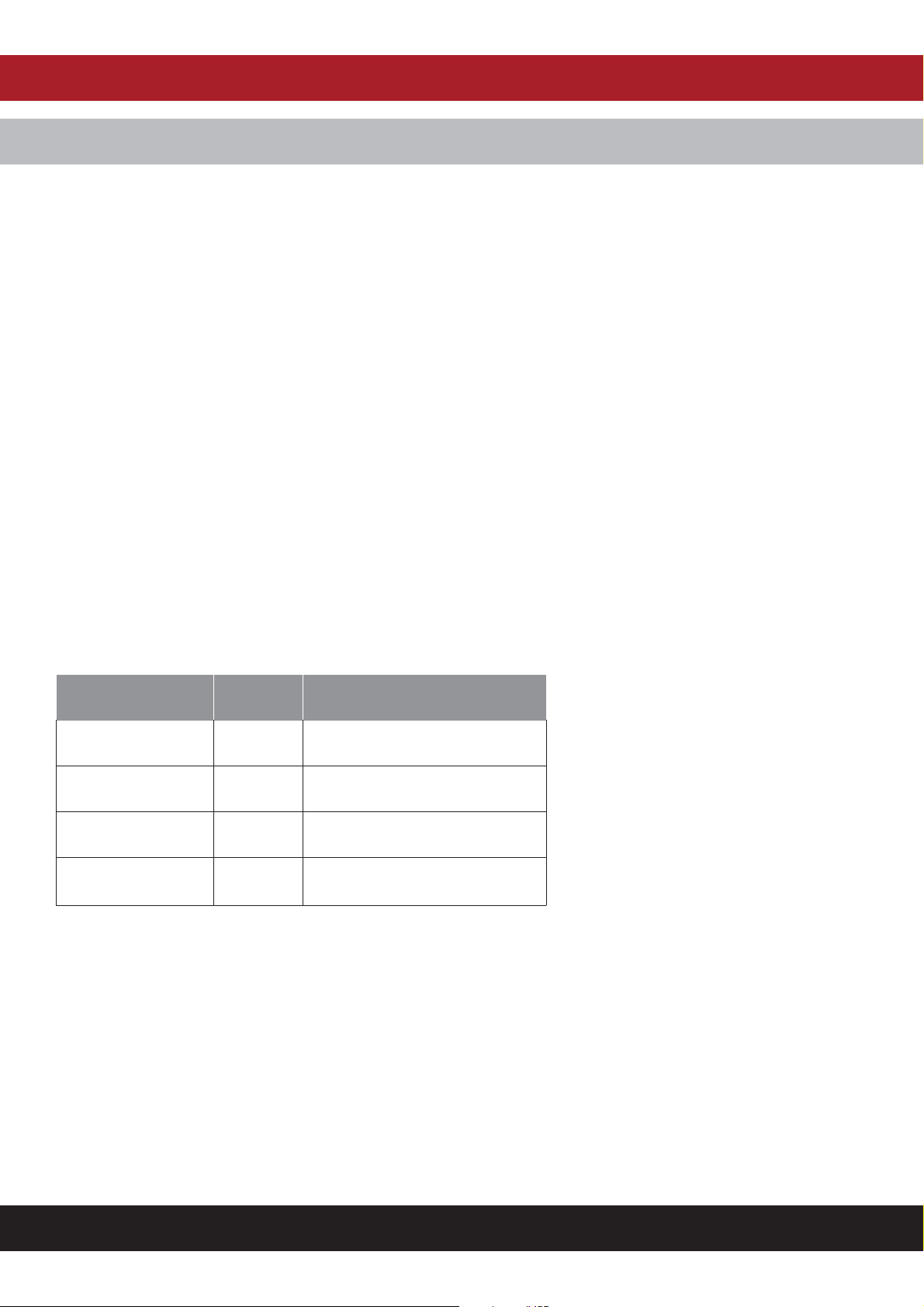
TEST BUTTON GREEN LED STATUS
Press for about 1 second OFF Emergency mode for 1 second
Press for about 3 seconds Blinking Functional test for 30 seconds
Press for about 5 seconds Flashing Duration test
Press again for about 5
seconds
Functional Interruption of duration test
INSTRUCTION MANUAL - Issue 1 - 02/2014 | 4
Page 5
CHANNEL SAFETY SYSTEMS t: 0845 884 7000 | w: www.channelsafety.co.uk
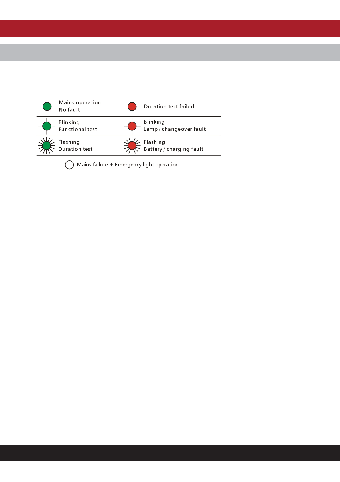
Meaning of the indicator LED
Green
The status display can only be cleared after the fault has been recti ed, mains voltage has been reapplied and a function test has been run.
Red
Changing The Rechargeable Battery
If the emergency duration is less than 180 min., the rechargeable battery has to be replaced. Use only original batteries from the manufacturer.
INSTRUCTION MANUAL - Issue 1 - 02/2014 | 5
Page 6

CHANNEL SAFETY SYSTEMS t: 0845 884 7000
Peters eld Business Park f: 0845 884 6000
Bedford Road
Peters eld
Hampshire e: [email protected]
GU32 3QA w: www.channelsafety.co.uk
INSTRUCTION MANUAL
 Loading...