


MDS-6A
Integrated Multi-Zone Controller
INSTALLATION MANUAL
AND
USER’S GUIDE
TM
MDS-6A

MDS-6A INSTALLATION MANUAL
TABLE OF CONTENTS
SECTION 1
Introduction
1.1 Feature Overview . . . . . . . . . . . . . . . . . . . . . . . . . . . .5
1.2 MDS-6A Specifications. . . . . . . . . . . . . . . . . . . . . . . . .6
1.3 MDS-6A Front Panel Adjustments . . . . . . . . . . . . . . . .7
SECTION 2
Connections and Settings
2.1 System Overview . . . . . . . . . . . . . . . . . . . . . . . . . . . .8 2.2 Wiring MCS Controllers to the MDS-6A . . . . . . . . . . . .9 2.3 Source and IR Connections . . . . . . . . . . . . . . . . . . . .11
SECTION 3 |
|
Troubleshooting |
|
3.1 MCS Controller Operation . . . . . . . . . . . . . . |
. . . . . . .12 |
3.2 Infrared . . . . . . . . . . . . . . . . . . . . . . . . . . . |
. . . . . . .13 |
3.3 Audio Source Control . . . . . . . . . . . . . . . . . . |
. . . . . .13 |
LIMITED WARRANTY . . . . . . . . . . . . . . . . . . . . . . . |
Back Page |
Page 2 |
© Channel Plus, Inc. 2004 • All rights reserved. 4/04 |

MDS-6A INSTALLATION MANUAL |
IMPORTANT SAFETY INFORMATION
Read Information—All the safety and operating information should be read before the appliance is operated.
Follow Information—All operating and use information should be followed.
Retain Information—The safety and operating information should be retained for future reference.
Heed Warnings—All warnings on the appliance and in the operating instructions should be heeded.
Wall Mounting—Mounting of this appliance should be done only by an authorized installer.
Ventilation—The appliances should be situated so that their location or position does not interfere with their proper ventilation. These appliances should never be placed near or over a radiator or heat register. These appliances should not be placed in a built-in installation such as a bookcase or cabinet that may impede the flow of air through the ventilation openings.
Non-Use Periods—Appliances that are left unattended and unused for long periods of time should be de-energized.
Power Sources—The appliances should be connected to a power supply only of the type described in the operating instructions or as marked on each appliance. If you are not sure of the type of power supply to your home, consult your authorized Channel Plus dealer or local power company.
Grounding or Polarization—These audio products must be connected to a grounding-type alternating-current circuit on a dedicated circuit breaker. This is a safety feature. The green safety wire from the A.C. circuit must be connected.
Water and Moisture—To reduce the risk of electric shock or fire, these appliances should not be used near water––for example, near a bathtub, washbowl, kitchen sink, laundry tub, in a wet basement, or near a swimming pool.
© Channel Plus, Inc 2004 • All rights reserved. 4/04 |
Page 3 |
MDS-6A INSTALLATION MANUAL
Power Cord Protection—A.C.Power supply circuits should be routed by a certified electrician only, in accordance with the NEC standards.
Telephones—Avoid using a telephone (other than a cordless type) during an electrical storm. There may be a remote risk of electrical shock from lightning. Do not use a telephone to report a gas leak if the leak is in the vicinity of the Channel Plus electronic equipment because of risk of fire or explosion.
Cleaning—Turn off the circuit breaker to this audio product before cleaning. Do not use liquid or aerosol cleaners. Use a damp cloth for cleaning.
Power Lines—An outdoor antenna should be located away from power lines. When installing an outside antenna system, extreme care should be taken to avoid touching power lines or circuits, as contact with them may be fatal.
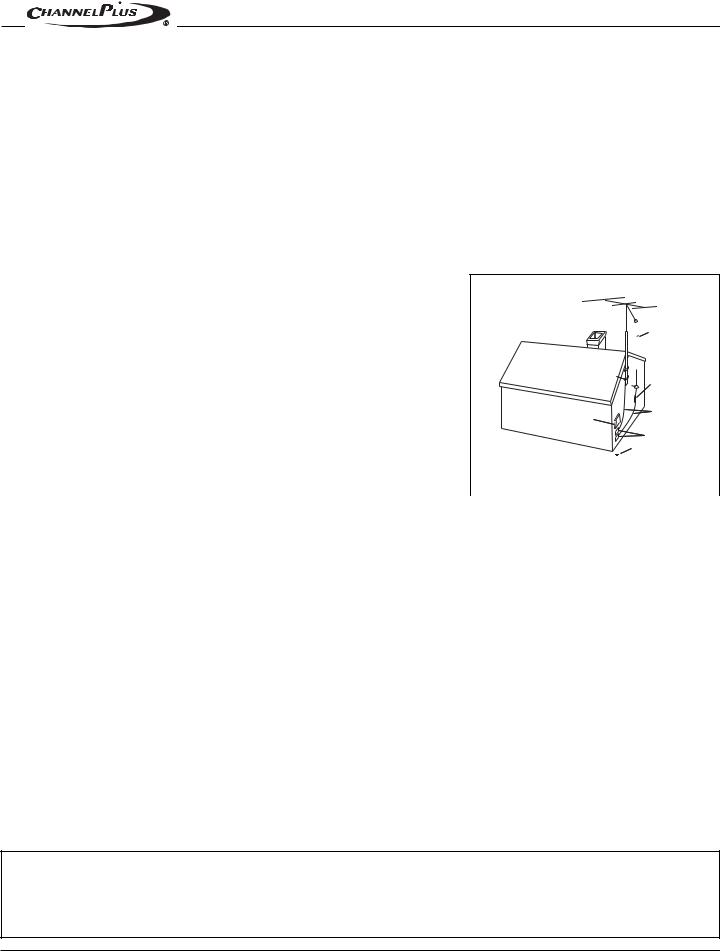
Outdoor Antenna Grounding—If an outside antenna or cable system is connected to these audio products, be sure the antenna or cable system is grounded so as to provide some protection against voltage surges and built-up static charges. Section 810 of the U.S. National Electrical Code, and Section 54 of the Canadian Electrical Code, provide information with
respect to proper grounding of the mast and supporting structure, grounding of the lead-in wire |
Grounding |
|
|
||
to an antenna discharge unit, size of grounding conductors, location of antenna-discharge unit, |
Diagram |
|
|
||
connection to grounding electrodes, and requirements for the grounding electrode. See the |
|
|
|
|
|
|
|
|
|
|
|
grounding diagram (right). |
|
|
|
|
ANTENNA |
|
|
|
|
LEAD-IN WIRE |
|
Overloading—Do not overload wall outlets and extension cords, as this could result in |
GROUND |
|
|
||
fire or electric shock. |
CLAMPS |
|
|
||
|
|
|
|
ANTENNA LEAD-IN WIRE |
|
|
|
|
|
|
|
|
|
|
|
|
(CEC SECTION 54-200) |
Object and Liquid Entry—Never insert objects of any kind through the openings |
|
|
|
|
(NEC SECTION 810-20) |
ELECTRIC |
|
GROUNDING CONDUCTORS |
|||
of these appliances, as they may touch dangerous voltage points or short-out parts that could |
SERVICE |
|
|||
EQUIPMENT |
|
(CEC SECTION 54-200) |
|||
|
|
|
|
(NEC SECTION 810-21) |
|
result in a fire or electric shock. Care should be taken so that objects do not fall and liquids are |
|
|
|
|
GROUND CLAMPS |
not spilled into the appliance through openings in the enclosure. |
|
|
|
POWER SERVICE GROUNDING |
|
|
NEC - NATIONAL ELECTRICAL CODE |
ELECTRODE SYSTEM |
|||
Servicing—Do not attempt to service these appliances yourself, as opening or removing |
(CEC SECTION 10-700) |
||||
CEC - CANADIAN ELECTRICAL CODE |
(NEC ARTICLE 250, PART H) |
||||
|
|
||||
covers may expose you to dangerous voltage or other hazards. Refer all servicing to qualified |
|
|
|
|
|
service personnel. |
|
|
|
|
|
Damage Requiring Service—These appliances should be serviced by qualified service personnel when:
•A power supply connection or a plug has been damaged or
•If liquid has been spilled into the appliance or objects have fallen into the appliance or
•The appliance has been exposed to water or moisture or
•The appliance does not appear to operate normally or exhibits a marked change in performance or
•The appliance has been dropped or the enclosure damaged.
Replacement Parts—When replacement parts are required, be sure the service technician has used replacement parts specified by the manufacturer or that have the same characteristics as the original part. Unauthorized substitutions may result in fire, electric shock, or other hazards.
Safety Check—Upon completion of any service or repairs to this audio product, ask the service technician to perform safety checks to determine that the audio product is in proper operating condition.
Lightning—For added protection for these audio products during an electrical storm, or when they are left unattended and unused for long periods of time, turn off the circuit breaker, and disconnect the antenna or cable system. This will prevent damage to the audio products due to lightning and power-line surges.
FEDERAL COMMUNICATIONS COMMISSION (FCC) NOTICE:
This device complies with Part 15 of the FCC Rules. Operation is subject to the following conditions: (1) This device may not cause harmful interference and (2) this device must accept any interference received, including interference that may cause undesired operation.
Page 4 |
© Channel Plus, Inc. 2004 • All rights reserved. 4/04 |

MDS-6A INSTALLATION MANUAL
SECTION 1 - INTRODUCTION
1.1 - FEATURE OVERVIEW
6 Sources / 6 Zones
The MDS-6A enables you to independently listen to and control up to six different audio sources (i.e. Tuner, CD, Tape Deck - and the audio signals from your VCR, DVD, and Satellite Receiver) in six distinct listening areas or “zones”.
12 Channel x 40 WPC Power Amplifier
The MDS-6A features 12 channels of amplification capable of delivering 40 watts per channel into 8 ohms. The MDS-6A provides more than enough clean, dynamic power to drive a house full of speakers all day long!
Compatible with MCS Zone Controllers and IR Receivers
The MDS-6A’s zones can be controlled using MCS-1A Zone Controllers,
MCS-2A Programmable Zone Controllers, and/or IR Receivers. Add multiple
MCS Controllers and/or IR Receivers for maximum flexibility.
User Feedback to All System Controllers
Unlike other basic multi-zone systems, the MDS-6A receives IR data and transmits feedback to MCS Controllers. These features inform the user of which Source is currently selected, Zone ON/OFF Status, Mute, Do-Not-Disturb, Whole-House Music Status, and more!
MCS Controller RJ-45 Jacks and Removable Speaker Terminals for Easy Connectivity
In addition to the six plug 'n play RJ45 jacks for MCS Controllers and IR Receivers, the MDS-6A features installer-friendly removable speaker terminals which accept up to 14 AWG wire.
6 Source-Specific IR Output Ports Plus 1”ALL” Port
Six source-specific IR output ports enable multiple ‘same make/model’ components to be used without conflict or interference. An IR ALL port is also provided.
© Channel Plus, Inc 2004 • All rights reserved. 4/04 |
Page 5 |
 Loading...