

Page 1

LED COLOUR TV
MAINTENANCE MANUAL
MODEL: LS09C CHASSIS
Please read this manual carefully before maintenance.
Page 2

CATALOG
Chapter1:Safety and notes............................................................................................3
Chapter2: TV specifications and ports functions.........................................................4
Chapter3: Software upgrade tooling,software upgrade instructions,software
initialization,parameter setting,software version and screen matching instructions......6
Chapter4:Repair process and examples of typical accident.......................................11
Chapter5: Factory model parameters setup instructions and precautions..................16
Chapter6:Instructions of simple factory debugging specification .............................19
2
Page 3

Chapter1:Safety and notes
1-1 Installation notes
(1) Please don't beat or rub, scratch the surface of the LCD screen heavily, don’t touch it with
hand casually.
(2) When the screen is dirty, please clean it with absorbent cotton or cotton cloths lightly.
(3) Please clean it timely when water or other viscosity pollution fall, which may make the LCD
face or color change.
(4) Please don’t make the LCD screen shocked by a strong external force.
1-2 Attention points of operation and using
(1) Please unplug the power cable before moving LCD screen.
(2) Please don’t change the mainboard’s original setting, otherwise brightness, white balance etc.
may not meet the specification.
(3) Radiation of long time use at room temperature is larger than at low temperature.
(4) Please note that the long displaying image may remain at the top when shutdown the
machine .
(5) Please avoid the impact from mobile phone to protect your TV.
1-3 Storage notes
(1)When store for a long time, please keep the temperature between 0℃to 40℃,don’t expose the
TV to the sun, the humidity should be less than 85%RH.
(2)Please don’t put your TV under high humidity and high temperature circumstance ,e.g
temperature: 60℃,humidity:85%RH.
(3)Please don’t put your TV under low temperature circumstance ,e.g temperature lower than
25℃.
1-4 Dismantling notes
(1)As LCD screen is easy to be damaged, when dismantle, please attention to protect.
(2)Please attention the position of each screw when dismantle, in case to beat the wrong position
when install which may lead to crack or slide of the face frame.
(3) If you need to dismantle the power board or the mainboard, please attention the position and
direction of each line, especially the direction of the screen line, in case of causing accident
when install. Before dismantle ,we can take some photos of the line route for the comparison
of installing.
(4)After check and maintenanc e, please assure that there is no foreign body in the machine when
install.
1-5 High-voltage warning
The high-voltage of the LCD screen is generated by the power supply step-up board, without
attention to exposure to high voltage, one may meet a serious electric shock.
3
Page 4
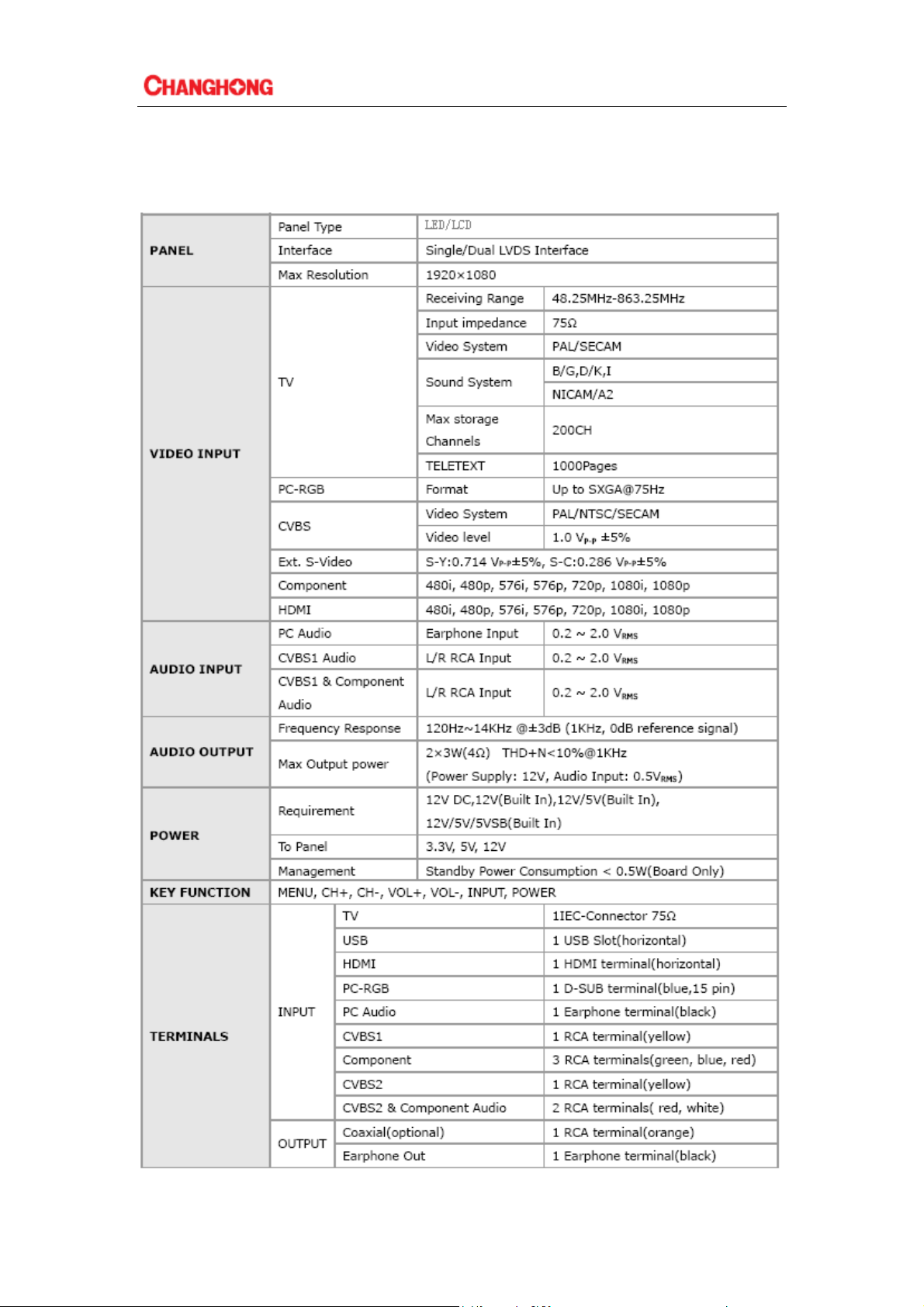
Chapter2: TV specifications and ports function
2-1 Basic specifications(The parameters are for reference only, the specifications should
accord to practicality of the batch orders)
4
Page 5
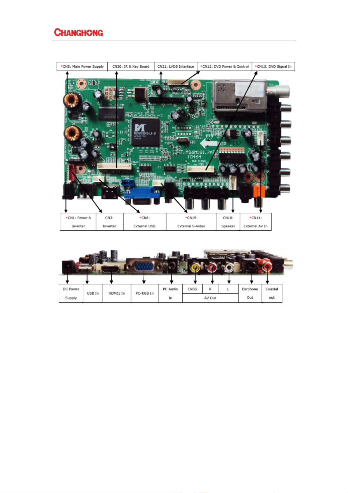
2-2 Introduction of ports(practicality photos)
ATTENTION:
1. HDMI and YPbPr support to 1080P;
2.The recommendation resolving ratio of VGA is 1024X768;
3. Av output supports TV input /AV output,Av input /AV output;
4.The picture is for a reference only,the actual item is the standard.
5
Page 6
Chapter3: Software upgrade tooling , software upgrade instructions ,
software initialization , parameter setting , software version and
screen matching instructions
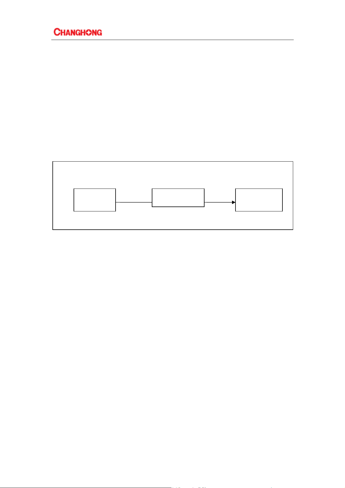
3-1 Software upgrade tooling
there are two kinds of using upgrade tooling:
1.Use the combined interface(the parallel port) upgrade tooling :use the upgrade program: ISP_
T ool V4.0.5.exe(a nd hi gher versions)
2.Use USB interface upgrade tooling , use the upgrade program : versions higher than ISP Tool
V4.3
3. Use the USB upgrade
Combined interface or USB
computer upgrade tooling LCD TV
VGA
3-2 Software upgrade instructions
3-2-1 Tooling upgrade
1. Driver Installation: Upgrade tooling connected to the computer via USB, the first connection
will be prompted to find the hardware, follow the prompts to install the driver, Driver file from the
attachment "usb-updateTOOL-DRIVER" folder inner tube MSTAR name of the subfolder word
where you can, you are prompted three times, three times to be installed.
2. After installing the driver tooling, tooling and TV connected (switched on), open the upgrade
tool "ISP_Tool V4.3.9.4.exe" (Note: The following chart version of the tool used for the
interception chart, the upgrade is still using V4 .3.9.4 version), run the upgrade program
6
Page 7
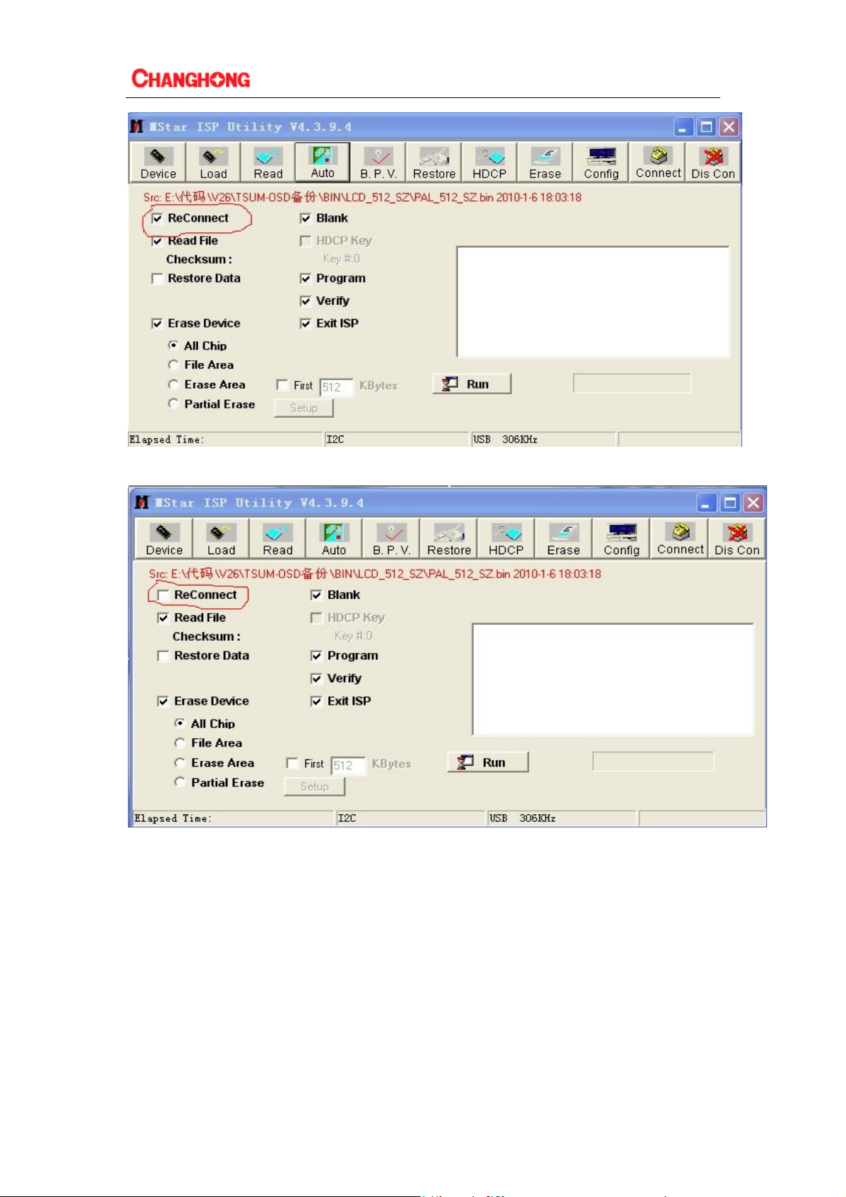
Cancel the selection in the red line frame of last chart , as following shows:
3.Select(connect)first ,if normal ,system will feedback the flash style of the machine chassis As
following
7
Page 8
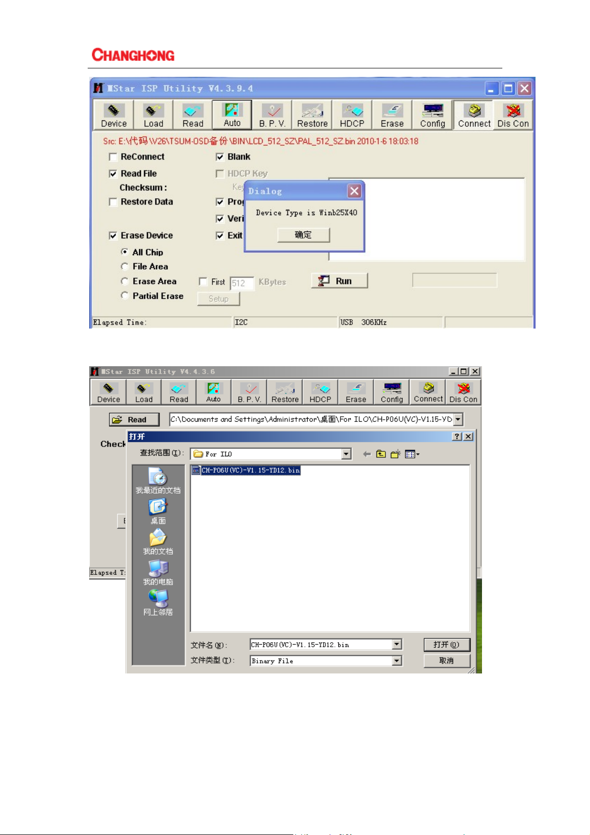
4.Select the toolbar on the "Read", then click on the bottom there's "Read", select the upgrade file,
such as "CH-P06U (VC)-V1.15-YD12.bin"
5. select "Auto", and check the options according to the following chart
8
Page 9

6. Select the top of the "Connect", if connected, there will be "Device Type" prompt, select "OK"
and then click "RUN",
After the upgrade is complete, the green "PASS" prompt will appear in the
progress bar below
9
Page 10

3-2-2 USB Upgrade
1) The first method
Copy the file to root catalogue of USB, The filename has to be for "bin_6m181. bin".Turn
on the TV, Insert the USB flash , .Entre the menu to choose "Sotfware Update(USB)", And press
key "ENTER" of remote control ,Then follow the on-screen prompt to request and complete
your update.
2) The second method
Copy the file to root catalogue of USB, The filename has to be for "bin_6m181. bin" ,Insert
the USB flash , then turn on the AC switch, update will be completed automatically, during
updating, The indicator will gleam.
3-3 Software initialization
After finishing the software upgrading ,enter into the factory menu ,select INIT TV,clear
EEPROM.
5-4Software version
Enter into the factory menu ,select SW INFORMATION
10
Page 11

Chapter4:Classical accident maintenance procedures and examples
4-1 Power Supply Trouble
4-2 Display Trouble(exceptional screen)
11
Page 12

4-3 Display Trouble (white screen)
4-4 Display Trouble(black screen)
12
Page 13

4-5 Audio Trouble(No sound)
4-6 Function Trouble(TV video)
13
Page 14

4-7 Function Trouble(PC)
4-8 Function Trouble(SCART、HDMI、YPbPr、DVB/TV)
14
Page 15

4-9 When you meet the following common problems, you might diagnose and
get the solutions without contacting with the technicians.
Symptoms Possible Reason Solutions
No picture, no sound, and no
indicator light on
abnormity Picture and sound
with
Picture is spotted or with snow
No picture, no sound and
indicator light is green
Blue screen, AV or SVIDEO is
displayed
Picture is unclear or shaking or
with black horizontal strips (in
VGA mode)
VGA picture is not centered
No sound
VGA picture display with
improper color
HDMI source, with snow pixel
of full screen
The remote control does not
work
1.The power cord is not plugged in
2.The power is off
1.Contrast, sharpness, and color are
set improperly
2.Color system is improperly
3.Sound system is improperly
Signal source is low-grade or the
signal cord is in a lower quality
Contrast, brightness, color and
volume are all in the minimum value
or TV is in mute mode.
The signal cable is not correctly
connected.
There is no signal input or the video
cable is not connected or incorrectly
connected
VGA picture is not correctly adjusted.
There is no audio signal input or audio
cable is not connected correctly
The color temp is adjusted incorrectly
by user
The signal source is not normal Plug the HDMI cable again
Batteries are improperly installed or
exhausted
1.Plug in the power cord
2.Turn the power on
1.Adjust the numerical value of
Contrast, sharpness, and color
2.Set the Color system to the
country broadcasting standard
3.Set the Sound system to meet
the country’s broadcasting
standard
Use the qualified signal cord
Adjust the value of contrast,
brightness, color and volume
Connect the signal cable
correctly
Connect the video cable
correctly
Enter “SETUP” menu, select
“Auto Tracking” item to
perform automatic calibration
and adjust “Phase” to solve the
problem
Connect the audio cable
correctly
Readjust the color temp, or
select the original color setting
1. Make sure the positive and
the negative polarities are
correct.
2.Check if there is a loose
contact between the batteries
and the springs
3.Replace the batteries
15
Page 16

Chapter5: Factory mode parameter setting instructions and notes
5-1 Enter into the factory mode
Switch on TV set, and make it works normally:
1.Press 【MENU】 key on the remote control
2.Press number keys “1”、“1”、“4”、“7” on remote control to enter password. Finish entering
the factory mode. If you want to quit the factory mode, Please. press【EIXT】key
Factory menu displays as bellow:
5-1-1ADC ADJUST (ONLY FOR YPBPR AND VGA)
1. AUTO ADC :AUTO ADJUST FOR Ypbpr CHANNEL
2.Restore Factory Def:RESET THE CHANGES
5-1-2.GENERAL SETING (Usually used)
W/B ADJUST(Usually used)
16
Page 17

1.W/B ADJUST(Usually used): Going to the white balance adjusting page.
2.PICTURE MODE: To change Parameters for different picture mode like mild worm…
3.Sound Mode :To change Parameters for different sound mode like standard music …
4.Volume curve :To change the volume page.note:the volume curve mode should not set here
WHITE PATTERN Press to generate 6 kinds of output pattern like white red…
5.Backlight :Press to change the voltage of PIN ADJ to change the brightness of the panel.
6.LVDS MAP:Press to change the Lvds map (Caution: Press this may close the output
signal ,you just keep press left or right or ok, and never press any key else especially key up and
down)
7.POWER MAP:
Set it to: 0 : Means you must press the power key to run the TV when it get power. ON: Auto
power on when get power Last: Go to the last state when it lost power supply.
Logo:
It will not show logo when open up if you set it to close.
5-1-3.DEBUG
17
Page 18

1.PQ NONLINEAR (Usually used)
MODE: Channel
PICTURE MDOE: Mostly we set it to standard
Brightness Curvel: To change the brightness page
Contrast Curve: To change the contrast page
Saturation Curve: To change the saturation page
Hue Curve: To change the hue page
Sharpness Curve: To change the sharpness page
Volume Curve: To change the volume page
All the CURVE are almost the same, so I only show Brightness curve as sample: Usually
we only change the OSD_50 item , it is correspond to the brightness of user OSD with the value
50. OSD_100 is correspond to the value 100 of user OSD who is the max brightness.
5-1-4. SW INFORMATION :Press to show the detail of the software like the time and the
checksum.
5-1-5. INIT TV: Initialize the TV totally, reset the EEPROM
5-1-6. INIT FAC CHANEL :Initialize the factory channel
5-1-7. Burn Mode: Go to burn mode (Power to exit)
5-2 Setting method of factory menu
1. Select the setting item
Operators can choose setting item with【P+】and【P-】key, font with background display means
the item has been chosen. Press【V+】key to enter sub directory. Use 【P+】and 【P-】keys on
remote control to select up and down, then use【V+】and【V-】keys to set.
2.Most of the menu functions are open under factory mode, if need , item checking and effect test
can be done by using menu .
3. TV signal switching can be done by directly pressing the number keys in factory mode .Press
【MENU】to back to the parental catalog ,press【EXIT】 to quit factory mode.
18
Page 19

Chapter6:Instructions of simple factory debugging specification
6-1 Clear EEPROM ,and set the parameters after upgrading according to the
upgrade instructions.
6-2 Check each channel/source to see if the image and sound are normal.
19
Page 20

1
CN2
+
1
12V
2
_
3
内径为
2.0mm-G
DC-001-
A A
CN3
1
12V
2
BL ON
3
ADJ
4
5
6
红色
-G
6PIN-2.0-D-H-
F1
12V
C5
0.1uF-0402-Y5V-+80%-20%-16V
3F.3150212021ZLQGMV
B B
470uF-25V-±20%-10*13
0.1uF-0402-Y5V-+80%-20%-16V
+12V
+
E3
C6
-
105
℃
2
CN1
1
12V
2
12V
3
12V
4
12V
BL ON
5
6
ADJ
7
GND
8
GND
9
GND
10
GND
NC/10PIN-2.0-D-H-G
CN5
1
2
3
4
5
6
NC/6PIN-2.0-D-H-G
+5V
+5V
GND
GND
+5V_STB
PW_ON
Power_ ON
3
+5V_STB
R9
R10
NC/510ohm-0402-±5%-1/16W
Q3
PW_ON
R12
Q5
R15
NC/4K7ohm-0402-±5%-1/16W
NC/PMBT3906
NC/10Kohm-0402-±5%-1/16W
NC/D-MMBT3904-7-F
NC/10Kohm-0402-±5%-1/16W
+5V_STB
PW_ON
C7
C8
NC/0.1uF-0402-Y5V-+80%-20%-16V
NC/0.1uF-0402-Y5V-+80%-20%-16V
4
+5V_STB
R1
+12V
R2
5V_SW
0ohm-1206-±5%-1/4W
NC/0ohm-1206-±5%-1/4W
NC/100uF-25V-±20%-6*7
NC/0.47uF-0603-Y5V-+80%-20%-16V
-
5V_SW
Power_ ON
0.1uF-0402-Y5V-+80%-20%-16V
10Kohm-0402-±5%-1/16W
NC/10Kohm-0402-±5%-1/16W
0.01uF-0402-X7R-±10%-50V
NC/100pF-0402-NPO-±5%-50V
0.01uF-0402-X7R-±10%-50V
2K2ohm-0402-±5%-1/16W
5
U1
BM1117-3.3(SOT-223)
+3.3V_STB
2
VI3VO
12
E1
C1
+
C21
C120
105
℃
GND
R25
R28
GND
4
ADJ1VO
RT8284NGSP
C18 0.01uF-0402-X7R-±10%-50V
8
U4
NC
IN2SW
E5
7
EN
GND
4
C29
C33
12
E2
C9
C3 0.1uF-0402-Y5V-+80%-20%-16V
C19
0.01uF-0402-X7R-±10%-50V
BS
COMP
FB
C30
R32
3
BS
5
DR2W4*5.5-10uH
5K1ohm-0402-±1%-1/16W
12Kohm-0402-±1%-1/16W
L2
1
6
6
-
100uF-16V-±20%-6*7
0.1uF-0402-Y5V-+80%-20%-16V
100uF-16V-±20%-6*7
NC/10uF-0805-X5R-±10%-6.3V
R27
470uF-16V-±20%-8*1 2
10uF-0805-X5R-±10%-6.3V
0.1uF-0402-Y5V-+80%-20%-16V
105
-
105
R24
+
E6
C23
-
℃
℃
+1.2V_VDDC
C26
105
℃
5V_SW
5V_SW
1uF-0603-Y5V-+80%-20%-10V
0.1uF-0402-Y5V-+80%-20%-16V
NC/0.1uF-0402-Y5V-+80%-20%-16V
7
L39
+3V3
2
VI3VO
U2
C10
4
ADJ1VO
C12 0.1uF-0402-Y5V-+80%-20%-16V
+
E22
BM1084-3.3(TO263-2)//NC/BM1117-3.3(SOT-223)
U3
BM1117-ADJ(SOT-223)
2
VI3VO
C15
Vref=1.25V
ADJ1VO
C17
C16
E4
4
R8
R11 100ohm-0402-±1%-1/16W
+3.3V
0ohm-0603-±5%-1/10W
0.1uF-0402-Y5V-+80%-20%-16V
NC/100uF-16V-±20%-6*7
AVDD_DDR_2.5V_
C13
+
91ohm-0402-±1%-1/16W
470uF-16V-±20%-8*12
0.1uF-0402-Y5V-+80%-20%-16V
8
-
105
℃
-
105
℃
5V_SW
R19
R20
Q6
R29
Q7
Q9
GND
10Kohm-0402-±5%-1/16W
510ohm-0402-±5%-1/16W
33ohm-0402-±5%-1/16W
510ohm-0402-±5%-1/16W
PMBT3904
NC/10Kohm-0402-±5%-1/16W
0.1uF-0402-Y5V-+80%-20%-16V
C20
R22
C31
C32
PVCC
R35
R36
A03407
NC/100uF-25V-±20%-6*7
0.1uF-0402-Y5V-+80%-20%-16V
100uF-16V-±20%-6*7
MGGB1005M301HT-LF
MGGB1005M301HT-LF
NC/10Kohm-0402-±5%-1/16W
BL ON
ADJ
L3
L4
CN4
PVCC
NC/2PIN-2.54-D-H-M
CN23
PVCC
3PIN-2.54-D-H-M
Q8
-
-
105
1
+12V
12V
2
PVCC
3
+3V3
3.3V
PVCC
2
+5V
1
5V
VCC-Panel
+
+
C35
E7
E23
105
℃
GND
℃
+5V_STB
R142
R21
C22
R23
5V_SW
R31
NC/4K7ohm-0402-±5%-1/16W
4K7ohm-0402-±5%-1/16W
100Kohm-0402-±5%-1/16W
3K3ohm-0402-±5%-1/16W
PMBT3904
R37
R38
+5V_STB
R17
R26
R30
C122
C121
8
1
C123
U7
+12V
R3
+5V
+5V_STB
0ohm-1206-±5%-1/4W
C C
D D
C126
GND
R187
10Kohm-0402-±5%-1/16W
4K7ohm-0402-±5%-1/16W
NC/0.47uF-0603-Y5V-+80%-20%-50V
IN2SW
7
EN
NC
RT8269GSP
GND
4
C196
6
BS
FB
COMP
C194
R188
0.1uF-0402-Y5V-+80%-20%-16V
0.01uF-0402-X7R-±10%-50V
0.01uF-0402-X7R-±10%-50V
TC5026U-470K-BK/NA
180Kohm-0402-±1%-1/16W
3
5
D34
100pF-0402-NPO-±5%-50V
0.01uF-0402-X7R-±10%-50V
10Kohm-0402-±5%-1/16W
SK34A-SMA
39Kohm-0402-±1%-1/16W
470uF-16V-±20%-8*12
0.1uF-0402-Y5V-+80%-20%-16V
NC/10Kohm-0402-±5%-1/16W
5V_SW
C125
GND
C204
GND
缺口向上)
0.1uF-0402-Y5V-+80%-20%-16V
+12VOFF
BL_ON
BL_ADJ
10Kohm-0402-±5%-1/16W
PMBT3904
1Kohm-0402-±5%-1/16W
510ohm-0402-±5%-1/16W
1uF-0603-Y5V-+80%-20%-10V
0.1uF-0402-Y5V-+80%-20%-16V
NC/10Kohm-0402-±5%-1/16W
+3.3V
P_panel
L13
R184
R186
+5VR5
+
E9
C193
-
105
℃
NC/0ohm-1206-±5%-1/4W
4K7ohm-0402-±5%-1/16W
100Kohm-0402-±5%-1/16W
47Kohm-0402-±5%-1/16W
PMBT3904
R185
Power_ ON
NC/0ohm-1206-±5%-1/4W
4K7ohm-0402-±5%-1/16W
100Kohm-0402-±5%-1/16W
47Kohm-0402-±5%-1/16W
PMBT3904
R192
Power_ ON
H1
Location holeH2Location holeH3Location holeH4Location hole
M1
MARKM2MARKM3MARKM4MARK
Q2
GND
+12V
Q23
GND
+5V
R7
R183
0.1uF-0402-Y5V-+80%-20%-16V
R190
R191
0.1uF-0402-Y5V-+80%-20%-16V
GND
WPM2341-3/TR
A03407
H5
Location hole
R4
Q1
R189
Q21
P1
22.5*22*6(
1
2
3
4
5
6
7
8
Page 21

1
5V_SW
1
5V_SW
C2
R47
GND
A A
NC/0.1uF-0402-Y5V-+80%-20%-16V
22pF-0402-NPO-±5%-50V
22pF-0402-NPO-±5%-50V
VGA_5V
D4
3
R56
B B
D351-015F-001-
AV1
黄、红、白
NC/AV3-8.4-06(
1
CVBS_I/O
2
3
AV_R_I/O
4
5
AV_L_I/O
6
CN14
C C
AV2_VIN1
L11
2
AV2_L_I
3
D61
4
C83
5
AV2_R_I
5PIN-2. 0-D-H-G
GND
AV2_R_I
AV2_L_I AV2L_I
C91
R156
GND
R167
C98
8K2ohm-0402-±5%-1/16W
12Kohm-0402-±5%-1/16W
470pF-0402-X7R-±10%-50V
1uF-0603-Y5V-+80%-20%-10V
C102
C103
8K2ohm-0402-±5%-1/16W
12Kohm-0402-±5%-1/16W
470pF-0402-X7R-±10%-50V
1uF-0603-Y5V-+80%-20 %-10V
AV2R_I
R147
D22 NC/ICVL0518030FR
R164
D23 NC/ICVL0518030FR
0ohm-0402-±5%-1/16W
NC/BAT54C-215
NC/10Kohm-0402-±5%-1/16W
NC/10Kohm-0402-±5%-1/16W
2
R57
C54
CN10
CKX3-3.5-11-G
短体
-G
8K2ohm-0402-±5%-1/16W
12Kohm-0402-±5%-1/16W
1uF-0603-Y5V-+80%-20%-10V
)-U
R132
R136
75ohm-0402-±5%-1/16W
0.047uF-0402-X7R-±10%-16V
SDFL1005Q2R2KT(F )
330pF-0402-X7R-±10%-50 V
33ohm-0402-±5%-1/16W
NC/ICVL0518030FR
VGA_SDA
VGA_SCL
C55
0ohm-0402-±5%-1/16W
C
R1
R
L1
L
C81
2
TXD/
R52
R53
R70
RXD/
GND
NC/33ohm-0402-±5%-1/16W
0ohm-0402-±5%-1/16W
VGA_TX
11
12
13
14
15
NC/ICVL0518030FR
MGGB1005M301HT-LF
NC/ICVL0518030FR
MGGB1005M301HT-LF
GND
D11
R86
PC_ARIN
PC_ALIN
R90
D12NC/ICVL0518030FR
GND
CVBS0
CN9
VS_VGA
HS_VGA
SCART-VIN
1716
R85
C11
R91
CVBS_I/O
AV_R_I/O
AV_L_I/O
VGA_Rin
1
6
VGA_Gin
2
7
VGA_Bin
3
8
4
VGA_RX
9
VGA_5V
5
10
NC/33ohm-0402-±5%-1/16W
GND
L8
D10
L9
NC/ICVL0518030FR
8K2ohm-0402-±5%-1/16W
12Kohm-0402-±5%-1/16W
1uF-0603-Y5V-+80%-20 %-10V
C14
470pF-0402-X7R-±10%-50V
470pF-0402-X7R-±10%-50 V
CN11
AOR
AIR
AOL
AGND
BGND
AIL
B
SWTCH
GGND
CLKOUT
G
DATA
RGND
DATAGND
R
BLNK
VGND
BLNKGND
VOUT
VIN
SHIELD
RC-210 1(CS-10 4)-
R148
R153
R157
L10
RXD/
R92
C62
C63
R69
R84
1
2
3
4
5
6
7
8
9
10
11
12
13
14
15
16
17
18
19
20
21
SCART_VIN
3
L5
GZ1005D600T(F)
D5
L6
GZ1005D600T(F)
D8
L7
GZ1005D600T(F)
D9
R80
R87
PC_ARI
PC_ALI
SCART-AROUT
SCART_R_IN
SCART-ALOUT
GND
GND
SCART_L_IN
SCART_Bin
SC_SW
GND
DL_TXD
SCART_Gin
DL_RXD
GND
GND
SCART_Rin
SCART_ FB
GND
GND
SCART-VOUT
SCART-VIN
GND
弯式
SCART-VIN
SCART_R_IN
SCART_L_IN
R105
R107
75ohm-0402-±5%-1/16W
0.047uF-0402-X7R-±10%-16V
0ohm-0402-±5%-1/16W
33ohm-0402-±5%-1/16W
C44
C49
C57
C61
100ohm-0402-±5%-1/16W
100pF-0402-NPO-±5%-50V
2K2ohm-0402-±5%-1/16W
C65
100ohm-0402-±5%-1/16W
33pF-0402-NPO-±5%-50V
2K2ohm-0402-±5%-1/16W
D1
NC/0ohm-0402-±5%-1/16W
NC/0ohm-0402-±5%-1/16W
NC/0ohm-0402-±5%-1/16W
PC_RIN
R48
75ohm-0402-±5%-1/16W
10pF-0402-NPO-±5%-50V
NC/ICVL0518030FR
PC_GIN
R66
75ohm-0402-±5%-1/16W
10pF-0402-NPO-±5%-50V
NC/ICVL0518030FR
PC_BIN
R75
75ohm-0402-±5%-1/16W
10pF-0402-NPO-±5%-50V
NC/ICVL0518030FR
PC_VSIN
PC_HSIN
D15
D16
C71
D17
NC/ICVL0518030FR
NC/ICVL0518030FR
NC/ICVL0518030FR
NC/ICVL0518030FR
ICVL0518030FR
CVBS2
D18
D19
NC/ICVL0518030FR
NC/ICVL0518030FR
NC/ICVL0518030FR
4
D20
D21
R130
SCART_R_IN
8K2ohm-0402-±5%-1/16W
12Kohm-0402-±5%-1/16W
R144
SCART_L_IN
8K2ohm-0402-±5%-1/16W
12Kohm-0402-±5%-1/16W
R42
100ohm-0402-±5%-1/16W
10uF-0805-Y5V-+80%-20%-10V
0.1uF-0402-Y5V-+80%-20%-16V
0.1uF-0402-Y5V-+80%-20%-16V
10uF-0805-Y5V-+80%-20%-10V
100Kohm-0402-±5%-1/16W
33Kohm-0402-±5%-1/16W
10uF-0805-Y5V-+80%-20%-10V
100Kohm-0402-±5%-1/16W
33Kohm-0402-±5%-1/16W
1uF-0603-Y5V-+80%-20%-10V
100Kohm-0402-±5%-1/16W
33Kohm-0402-±5%-1/16W
1uF-0603-Y5V-+80%-20%-10V
100Kohm-0402-±5%-1/16W
33Kohm-0402-±5%-1/16W
1uF-0603-Y5V-+80%-20%-10V
100Kohm-0402-±5%-1/16W
33Kohm-0402-±5%-1/16W
1uF-0603-Y5V-+80%-20%-10V
100Kohm-0402-±5%-1/16W
33Kohm-0402-±5%-1/16W
YPbPr_SW1
SCART_Rin
R109 75ohm-0402-±5%-1/16W
R108
R115
SC_SW
10Kohm-0402-±5%-1/16W
3K3ohm-0402-±5%-1/16W
R114
SCART_ FB
100ohm-0402-±5%-1/16W
R120
75ohm-0402-±5%-1/16W
100pF-0402-NPO-±5%-50V
NC/2.4V-LL-34-1/2W
C80
C82
R135
470pF-0402-X7R-±10%-50V
1uF-0603-Y5V-+80%-20 %-10V
C90
C96
R155
470pF-0402-X7R-±10%-50 V
1uF-0603-Y5V-+80%-20%-10V
C38
C37
YPbPr_YIN
YPbPr_PbIN
YPbPr_PrIN
33ohm-0402-±5%-1/16W
R79
YPbPr_PbI
DVD_Pb
YPbPr_Pb
YPbPr_YI
DVD_Y
YPbPr_Y
SCART_BinSCART_Gin
R110
C76
SCART1_FS
R122
FB
C79
SCART_RI
SCART_LI
5
+5V_VID5V_SW
C40
C41
C51
C58
U6
1
S
VCC
2
I0A
3
I0D
I1A
4
I1D
YA
5
YD
I0B
6
I0C
I1B
7
I1C
YB
8
YC
GND
CBT3257AD
75ohm-0402-±5%-1/16W
100pF-0402-NPO-±5%-50V
75ohm-0402-±5%-1/16W
D14
R44
YPbPr_YI
R49
10uF-0805-Y5V-+80%-20%-10V
100Kohm-0402-±5%-1/16W
33Kohm-0402-±5%-1/16W
R62
YPbPr_PbI
R71
1uF-0603-Y5V-+80%-20%-10V
100Kohm-0402-±5%-1/16W
33Kohm-0402-±5%-1/16W
R76
YPbPr_PrI
R81
1uF-0603-Y5V-+80%-20%-10V
100Kohm-0402-±5%-1/16W
33Kohm-0402-±5%-1/16W
+5V_VID
16
15
E
14
13
12
11
YPbPr_PrI
10
DVD_Pr
YPbPr_Pr
9
C42
SCART_Gin
C52
SCART_Bin
C59
SCART_Rin
YPbPr_YIN
YPbPr_PbIN
YPbPr_PrIN
+12VOFF
R131
0ohm-0402-±5%-1/16W
0.1uF-0402-Y5V-+80%-20%-16V
10Kohm-0402-±5%-1/16W
1000pF-0402-X7R-±10%-50V
270Kohm-0402-±5%-1/16W
PMBT3904
510ohm-0402-±5%-1/16W
220ohm-0402-±5%-1/16W
R146
SCART_LOUT
C93
6
R45
SCART_Gi
R50
R63
SCART_Bi
R72
R77
SCART-RI
R82
C850.1uF-0402-Y5V-+80%-20%-16V
C86
R152
R158
PC_GIN
PC_BIN
PC_RIN
R95
R98
R99
NC/0ohm-0402-±5%-1/16W
NC/0ohm-0402-±5%-1/16W
NC/0ohm-0402-±5%-1/16W
12V_SCOUT
1uF-0603-Y5V-+80%-20%-10V
R137
47Kohm-0402-±5%-1/16W
1000pF-0402-X7R-±10%-50V
Q19
C97
R161
C53
C60
YPbPr_Y
YPbPr_Pb
YPbPr_Pr
SCART-ALOUT
C100
7
R46
C43
PC_GI
R51
R64
PC_BI
R73
R78
PC_RI
R83
YPbPr_SW1
33ohm-0402-±5%-1/16W
R43
PC_BI
SCART_Bi
BIN
PC_GI
SCART_Gi
YIN
BIN
YIN
RIN
YPbPr_Pb
YPbPr_Y
YPbPr_Pr
10Kohm-0402-±5%-1/16W
1000pF-0402-X7R-±10%-50V
270Kohm-0402-±5%-1/16W
PMBT3904
510ohm-0402-±5%-1/16W
220ohm-0402-±5%-1/16W
R143
SCART_ROUT
C92
GND
U5
1
2
3
4
5
6
7
8
CBT3257AD
R58
0.047uF-0402- X7R-±10%-16V
33ohm-0402-±5%-1/16W
R61
1000pF-0402-X7R-±10%-50V
0ohm-0402-±5%-1/16W
R67
0.047uF-0402- X7R-±10%-16V
33ohm-0402-±5%-1/16W
R74
0.047uF-0402- X7R-±10%-16V
33ohm-0402-±5%-1/16W
R89
0.047uF-0402-X7R-±10%-16V
33ohm-0402-±5%-1/16W
R93
1000pF-0402-X7R-±10%-50V
0ohm-0402-±5%-1/16W
R97
0.047uF-0402-X7R-±10%-16V
33ohm-0402-±5%-1/16W
R101
0.047uF-0402-X7R-±10%-16V
33ohm-0402-±5%-1/16W
12V_SCOUT
R133
Q18
R149
R159
GND
CVBS_I/O
AV_R_I/O
AV_L_I/O
8
16
S
VCC
15
I0A
E
14
I0D
I1A
13
I1D
YA
12
YD
I0B
11
I0C
I1B
10
I1C
YB
9
YC
GND
C47
C48
C50
C56
YPbPr_Pb_IN
C64
C66
YPbPr_SOG
C69
YPbPr_Y_IN
C70
YPbPr_Pr_IN
1uF-0603-Y5V-+80%-20%-10V
47Kohm-0402-±5%-1/16W
1000pF-0402-X7R-±10%-50V
C94
R162
R163
SCART-VOUT
R165
SCART-AROUT
R166
SCART-ALOUT
NC/0ohm-0402-±5%-1/16W
NC/0ohm-0402-±5%-1/16W
NC/0ohm-0402-±5%-1/16W
+5V_VID
GND
PC_VSIN
FB
PC_VSIN/FB
PC_RI
SCART-RI
RIN
B_IN
Y_SOG
Y_IN
R_IN
SCART-AROUT
C101
GND
9
NC/4PIN-2.0-D-H-G
CN12
1
2
3
4
5
6
7
8
8PIN-2. 0-D-H-G
CN13
1
2
3
4
5
6
7
8
9
10
11
11PIN-2.0-D-H-G
CN7
DVD_+5V
DVD_+5V
GND
GND
DVD_IR/
DAT/RX
STB/TX
CN6
1
2
3
4
4PIN-2.0-D-H-G
10uF-0805-Y5V-+80%-20%-10V
ULCE0505A015FR
15Kohm-0402-±5%-1/16W
ULCE0505A015FR
15Kohm-0402-±5%-1/16W
CN8
1
1
2
2
3
3
4
4
5
C256 0.1uF-0402-Y5V-+80%-20%-16V
6
7
8
RUSB-UK-04WH
FSMD110
10uF-0805-Y5V-+80%-20%-10V
ULCE0505A015FR
15Kohm-0402-±5%-1/16W
ULCE0505A015FR
15Kohm-0402-±5%-1/16W
C210
+12V
C211
R196
GND
USB_PPON
NC/0.47uF-0603-Y5V-+80%-20%-16V
100ohm-0402-±5%-1/16W
0.1uF-0402-Y5V-+80%-20%-16V
C78
1 2
1 2
R119
R125
R127
100ohm-0402-±5%-1/16W
100ohm-0402-±5%-1/16W
100ohm-0402-±5%-1/16W
R265
75ohm-0402-±5%-1/16W
COAX
75ohm-0402-±5%-1/16W
GND
75ohm-0402-±5%-1/16W
DVD_R_IN
100pF-0402-NPO-±5%-50V
GND
DVD_L_IN
NC/0ohm-0402-±5%-1/16W
DVD_Pb
GND
DVD_Pr
GND
DVD_Y
GND
USB5V
C36
D2
NC/0ohm-1206-±5%-1/4W
R193
USB5V
F2
C46
D6
1 2
C208
8
U8 RT8284NGSP
NC
IN2SW
7
EN
GND
4
C214
R112
DVD_ON
FB1
FB2
+12VOFF
DVD_IR/SPI R121
DVD/DAT
STB/RST
R128
R129
R138
R139
R141
C89
10
R40
D3
1 2
1 2
USB_5V
DUSB_DM
DUSB_DP
R54
D7
1 2
C209
1
BS
3
5
FB
COMP
6
C213
R198
NC/GZ1608D121T(F)
GZ3216D121T(F)
NC/100ohm-0402-±5%-1/16W
4K7ohm-0402-±5%-1/16W
4K7ohm-0402-±5%-1/16W
4K7ohm-0402-±5%-1/16W
R124
R126
NC/4K7ohm-0402-±5%-1/16W
NC/4K7ohm-0402-±5%-1/16W
DUSB2_DM
DUSB2_DP
R41
R55
0.1uF-0402-Y5V-+80%-20%-16V
0.01uF-0402-X7R-±10%-50V
0.01uF-0402-X7R-±10%-50V
TC5026U-470K-BK/NA
180Kohm-0402-±1%-1/16W
L28
R195
D35
R197
NC/100pF-0402-NPO-±5%-50V
0.01uF-0402-X7R-±10%-50V
2K2ohm-0402-±5%-1/16W
NC/SK34A-SMA
39Kohm-0402-±1%-1/16W
470uF-16V-±20%-8*12
0.1uF-0402-Y5V-+80%-20%-16V
+3.3V
+
E11
-
105
USB_5V
C212
℃
1Kohm-0402-±5%-1/16W
PMBT3904
4K7ohm-0402-±5%-1/16W
100Kohm-0402-±5%-1/16W
10Kohm-0402-±5%-1/16W
NC/10Kohm-0402-±5%-1/16W
11
+5V
USB_5V
R100
DVD_ON
R102
8K2ohm-0402-±5%-1/16W
12Kohm-0402-±5%-1/16W
DVD_L_IN
8K2ohm-0402-±5%-1/16W
12Kohm-0402-±5%-1/16W
NC/0ohm-1206-±5%-1/4W
0ohm-1206-±5%-1/4W
R199
R200
R103
R134
R151
R94
Q13
C88
R140
C99
R160
WPM2341-3/TR
Q12
R96
DVD_RIDVD_R_IN
C87
470pF-0402-X7R-±10%-50V
1uF-0603-Y5V-+80%- 20%-10V
C95
DVD_LI
470pF-0402-X7R-±10%-50V
1uF-0603-Y5V-+80%-20%-10V
12
DVD_+5V
AV2
YPbPr_YIN
1
2
YPbPr_PbIN
3
4
YPbPr_PrIN
5
6
AV4
1
AV1_IN
D D
2
AV1_RIN
3
4
AV1_LIN
5
6
绿、蓝、红
AV3-8.4-06(
NC/ICVL0518030FR
75ohm-0402-±5%-1/16W
75ohm-0402-±5%-1/16W
NC/ICVL0518030FR
黄、红、白
AV3-8.4-06(
)-U
D24NC/ICVL0518030FR
D26
)-U
D29
1
R17175ohm-0402-±5%-1/16W
YPbPr_PbIN
R174
YPbPr_PrIN
R179
AV1_INYPbPr_YIN
L12
D25
AV1_RIN
D27
1 2
AV1_LIN
D30
1 2
2
R168
CVBS1
C104
R169
0.047uF-0402-X7R-±10%-16V
33ohm-0402-±5%-1/16W
75ohm-0402-±5%-1/16W
SDFL1005Q2R2KT(F)
NC/ICVL0518030FR
R173
R178
AV1_RI
C110
C111
1uF-0603-Y5V-+80%-20%-10V
R175
8K2ohm-0402-±5%-1/16W
12Kohm-0402-±5%-1/16W
NC/ICVL0518030FR
NC/470pF-0402-NPO-±5%-50V
AV1_LI
C114
C115
1uF-0603-Y5V-+80%-20%-10V
R180
8K2ohm-0402-±5%-1/16W
12Kohm-0402-±5%-1/16W
NC/ICVL0518030FR
NC/470pF-0402-NPO-±5%-50V
CN15
4PIN-2.0-D-H-G
3
SPDIF_OUT
220ohm-0402-±5%-1/16W
100ohm-0402-±5%-1/16W
0.1uF-0402-Y5V-+80%-20%-16V
330pF-0402-X7R-±10%-50V
1
GND
SC_IN
2
3
GND
SY_IN
4
4
R170
R172
R181
R182
D31
C117
0.01uF-0402-X7R-±10%-50V
33ohm-0402-±5%-1/16W
100pF-0402-NPO-±5%-50V
75ohm-0402-±5%-1/16W
NC/ICVL0518030FR
R176
R177
D28
C113
0.01uF-0402-X7R-±10%-50V
33ohm-0402-±5%-1/16W
75ohm-0402-±5%-1/16W
330pF-0402-X7R-±10%-50V
NC/ICVL0518030FR
AV3
C107
COAX
1
C109
2
橙
)
AV-8.4-5(
C116
S_CIN
C112
S_YIN
5
6
7
8
9
10
11
12
Page 22

1
2
3
4
A A
CN16
23
22
21
20
19
18
17
16
15
14
13
12
11
10
9
8
B B
7
6
5
4
3
2
1
GND
RX_HOTPLUG
HDMI_5V
GND
HDMI_SDA'
HDMI_SCL'
ARC'
HDMI_CEC
HDMI_RXC-
GND
HDMI_RXC+
HDMI_RX0-
GND
HDMI_RX0+
HDMI_RX1-
GND
HDMI_RX1+
HDMI_RX2-
GND
HDMI_RX2+
HDMI_CEC
R203
HDMI-CEC
220ohm-0402-±5%-1/16W
C215
ARC'
HDMI_RXC-
HDMI_RXC+
HDMI_RX0-
D50
HDMI_RX0+
D51
HDMI_RX1-
D46
HDMI_RX1+
D47
D48
D49
HDMI_RX2-
HDMI_RX2+
D44
D45
R205
HDMI_SDA'
HDMI_SCL'
D52
D53
0.047uF-0402-X7R-±10%-16V
33ohm-0402-±5%-1/16W
HDMI_CEC
D54
ARC
ARC'
D55
471511051
NC/ULCE0505A015FR
NC/ULCE0505A015FR
NC/ULCE0505A015FR
R206
+5V_STB
C C
HDMI_5V
1
3
HDMI+5V
2
D56 BAT54C-215
NC/ULCE0505A015FR
NC/ULCE0505A015FR
NC/0ohm-0402-±5%-1/16W
4K7ohm-0402-±5%-1/16W
R208 4K7ohm-0402-±5%-1/16WR207
22ohm-0402-±5%-1/16W
22ohm-0402-±5%-1/16W
22pF-0402-NPO-±5%-50V
22pF-0402-NPO-±5%-50V
HDMI_SCL'
HDMI_SDA'
C216
C217
R209
R229
NC/ULCE0505A015FR
NC/ULCE0505A015FR
NC/ULCE0505A015FR
NC/ICVL0518030FR
NC/ICVL0518030FR
HDMI_SCL
HDMI_SDA
NC/ICVL0518030FR
NC/ICVL0518030FR
D D
1
2
3
4
Page 23

1
2
3
4
5
6
7
8
5V_SW
GND
+2.5V_PGA
GZ1608D121T(F)
0.1uF-0402-Y5V-+80%-20%-16V
C150
AVSS_PGA
L21
C162
C165
VCC-Panel
GND
GND
RXO0+RXO0RXO1+RXO1RXO2+
RXOC+
RXO3+
RXE0+
RXE1+
RXE2+
GND
RXEC+
RXE3+
NC/5pF-0402-NPO-±5%-50V
NC/5pF-0402-NPO-±5%-50V
M_SCL
M_SDA
29
A0
30
A1
31
A2
32
A3
35
A4
36
A5
37
A6
38
A7
39
A8
40
A9
41
A11
42
A12
28
A10/AP
21
WE
22
CAS
23
RAS
26
BA0
16
LDQS
20
LDM
47
UDM
51
UDQS
27
BA1
24
CS
14
NC
17
NC
34
VSS
48
VSS
66
VSS
6
VSSQ
12
VSSQ
52
VSSQ
58
VSSQ
64
VSSQ
W9425G6JH-4/EM13S2561616A-5T
R234
CLKN0
R235
CLK0
22ohm-0402-±1%-1/16W
22ohm-0402-±1%-1/16W
AVDD_DDR_2.5V_
0ohm-0603-±5%-1/10W
NC/10uF-0805-X5R-±10%-6.3V
0.1uF-0402-Y5V-+80%-20%-16V
0.1uF-0402-Y5V-+80%-20%-16V
0.1uF-0402-Y5V-+80%-20%-16V
0.1uF-0402-Y5V-+80%-20%-16V
0.1uF-0402-Y5V-+80%-20%-16V
0.1uF-0402-Y5V-+80%-20%-16V
0.1uF-0402-Y5V-+80%-20%-16V
0.1uF-0402-Y5V-+80%-20%-16V
0.1uF-0402-Y5V-+80%-20%-16V
MGGB1005M301HT-LF
C178
C181
+3.3V_STB
R272
R276
SPI_WP0N
7
5V_SW
R210
CN19
1
R212
RXD/
2
R213
TXD/
3
+3.3V_STB
KEYA
KEYB
+3.3V_STB
4
4PIN-2.0-D-H-
蓝色
+3.3V_STB +3.3V_STB
C132
C131
NC/1uF-0603-Y5V-+80%-20%-10V
0.1uF-0402-Y5V-+80%-20%-16V
SGM810-SXN3L
100Kohm-0402-±5%-1/16W
1000pF-0402-X7R-±10%-50V
NC/100ohm-0402-±1%-1/16W
R249
0.047uF-0402-X7R-±10%-16V
68ohm-0402-±5%-1/16W
R250
0.047uF-0402-X7R-±10%-16V
68ohm-0402-±5%-1/16W
R252
0.047uF-0402-X7R-±10%-16V
0.047uF-0402-X7R-±10%-16V
68ohm-0402-±5%-1/16W
C167
C168
0.1uF-0402-Y5V-+80%-20%-16V
10uF-0805-Y5V-+80%-20%-10V
0.1uF-0402-Y5V-+80%-20%-16V
L23
10uF-0805-Y5V-+80%-20%-10V
GZ1608D121T(F)
1uF-0603-Y5V-+80%-20%-10V
GZ1608D121T(F)
+1.2V_VDDC
0.1uF-0402-Y5V-+80%-20%-16V
MGGB1005M301HT-LF
2
A A
C128
C129
20pF-0402-NPO-±5%-50V
20pF-0402-NPO-±5%-50V
1Mohm-0402-±5%-1/16W
33ohm-0402-±5%-1/16W
24MHz-±30PPM-20PF-HC-49S
R216
+5V_STB
R215
XTALO
Y1
XTALI
R230
L14
5V_IR
LED_R/
LED_G/
IR
GND
K0/AD
K1
K2
K3
K4/AD
K5
K6
K7
GND
R231
C139
R236
L15
L16
R237
R238
R240
R241
R243
R244
R245
R248
75ohm-0402-± 5%-1/16W
3K3ohm-0402-±5%-1/16W
5K6ohm-0402-±5%-1/16W
12Kohm-0402-± 5%-1/16W
0.1uF-0402-Y5V-+80%-20%-16V
ICVL0518030FR
5K6ohm-0402-±5%-1/16W
75ohm-0402-± 5%-1/16W
12Kohm-0402-± 5%-1/16W
0.1uF-0402-Y5V-+80%-20%-16V
REMOTE
C137
C141
D32
D33
C142
+5V_STB
LED_R'
LED_G'
R239
R242
R246
R247
ICVL0518030FR
4K7ohm-0402-±1%-1/16W
100ohm-0402-±1%-1/16W
3K3ohm-0402-±5%-1/16W
4K7ohm-0402-±1%-1/16W
100ohm-0402-±1%-1/16W
IR
MGGB1005M301HT-LF
4K7ohm-0402-±5%-1/16W
100ohm-0402-±5%-1/16W
22pF-0402-NPO-±5%-50V
CN20
1
B B
2
3
4
5
6
7
8
9
10
11
12
13
14
14PIN-2.0-D-H-G
MGGB1005M301HT-LF
MGGB1005M301HT-LF
0ohm-0402-±5%-1/16W
0.1uF-0402-Y5V-+80%-20%-16V
+3.3V_STB
R254
R253
C C
LED_R
4K7ohm-0402-±5%-1/16W
510ohm-0402-±5%-1/16W
+3.3V_STB
R258
LED_G
4K7ohm-0402-±5%-1/16W
10Kohm-0402-±5%-1/16W
LED_R'
5V_SW
R256
LED_G'
R259
Q22
510ohm-0402-±5%-1/16W
PMBT3904
AVDD_DVI+3.3V_STB
L25
GZ1608D121T(F)
C191
C192
D D
L26
AVDD_DMPLL
C206
MGGB1005M301HT-LF
0.1uF-0402-Y5V-+80%-20%-16V
1uF-0603-Y5V-+80%-20%-10V
0.1uF-0402-Y5V-+80%-20%-16V
1
R211
RXD
4K7ohm-0402-±5%-1/16W
4K7ohm-0402-±5%-1/16W
100ohm-0402-±5%-1/16W
100ohm-0402-±5%-1/16W
NC/ICVL0518030FR
NC/ICVL0518030FR
Q20
C133
R225
HPD_SINK_
R221
TXD
M_RESET
GND
-G
AVDD_DVI
+1.2V_VDDC
PC_HSIN
B_IN
Y_SOG
Y_IN
C149
GIN0M
R_IN
PC_VSIN/FB
+1.2V_VDDC
AVDD_DDR_2.5V_
C169
C151
+3.3V_STB
C159
C160
C170
YPbPr_Pb_IN
YPbPr_SOG
YPbPr_Y_IN
GIN2M
YPbPr_Pr_IN
S_YIN
S_CIN
CVBS2
CVBS1
CVBS0
VCOM0
CVBS_OUT
PC_ALI
PC_ARI
AV1_LI
AV1_RI
AUVRM
AUVRP
AUVAG
L29
AVDD_DDR_2.5V_
C186
C183
DVDD_DDR_1.2V
L27
0.1uF-0402-Y5V-+80%-20%-16V
12
D57
GND
12
D59
NC/ICVL0518030FR
GND
REMOTE
HDMI-CEC
M_RESET
HDMI_RXC-
HDMI_RXC+
HDMI_RX0HDMI_RX0+
HDMI_RX1HDMI_RX1+
HDMI_SDA
HDMI_RX2HDMI_RX2+
HDMI_SCL
ARC
GND
C187
C205
12
D58
1
IRIN
2
CEC
3
RESET
4
HOTPLUGA
5
RXCN
6
RXCP
7
RX0N
8
RX0P
9
AVDD_DVI_3.3V
10
RX1N
11
RX1P
12
DDCDA_DA
13
RX2N
14
RX2P
15
DDCDA_CK
16
ARC
17
NC
18
NC
19
NC
20
NC
21
NC
22
NC
23
NC
24
VDDC
25
HSYNC0
26
BIN0P
27
SOGIN0
28
GIN0P
29
GIN0M
30
RIN0P
31
VSYNC0
32
AVDD1P2
33
AVDD2P5_ADC
34
BIN1P
35
SOGIN1
36
GIN1P
37
GIN1M
38
RIN1P
39
AVDD3P3_ADC
40
CVBS4
41
CVBS3
42
CVBS2
43
CVBS1
44
CVBS0
45
VCOM
46
CVBS_OUT1
47
LINEIN_L0
48
LINEIN_R0
49
LINEIN_L1
50
LINEIN_R1
51
VRM
52
VRP
53
VAG
54
AVDD_AU25
C166
+3.3V
GZ1608D121T(F)
10uF-0805-X5R-±10%-6.3V
0.1uF-0402-Y5V-+80%-20%-16V
C188
C189
100pF-0402-NPO-±5%-50V
100pF-0402-NPO-±5%-50V
100pF-0402-NPO-±5%-50V
100pF-0402-NPO-±5%-50V
100pF-0402-NPO-±5%-50V
2.2uF-0603-Y5V-+80%-20%-10V
C207
10uF-0805-X5R-±10%-6.3V
0.1uF-0402-Y5V-+80%-20%-16V
0.1uF-0402-Y5V-+80%-20%-16V
0.1uF-0402-Y5V-+80%-20%-16V
DVDD_NODIE_1.2V
C127
2.2uF-0603-Y5V-+80%-20%-10V
+5V_STB
R13
4K7ohm-0402-±5%-1/16W
SPI_WP0N
LED_R
Power_ ON
USB_PPON
214
216
213
215
217
E-pad
GPIO8/PM5/RX
GPIO9/PM6/CS1
RXD
TXD
BL_ON
SCART1_FS
KEYA
KEYB
207
208
209
210
211
212
DDCA_CK
DDCA_DA
GPIO11/SAR0
GPIO12/SAR1
GPIO13/SAR2
GPIO6/PM1/TX
GPIO10/PMGPIO
GND
+3.3V
100ohm-0402-±5%-1 /16W
100ohm-0402-±5%-1 /16W
+1.2V_VDDC
M_SDA
M_SCL
R224
SPI-SCK
SPI-CS0N
SPI-SDI
SPI-SDO
204
202
206
203
205
SPI_DI
SPI_CZ
SPI_CK
SPI_DO
R223
A_MCLK
DUSB_DP
DUSB_DM
DUSB2_DM
197
196
198
DP_P0
DM_P0
DM_P1
A_MADR4
186
187
188
189
190
193
194
195
TESTPIN
DDCR_CK
185
192
191
VDDC
VDDP_3
DDCR_DA
A_DDR1_A8
A_DDR1_A7
A_DDR1_A6
A_DDR1_A5
A_DDR1_A4
DVDD_NODIE_1.2V
DUSB2_DP
200
201
199
DP_P1
GND_EFUSE
AVDD_NODIE
DVDD_NODIE
A_MADR5
A_MADR7
A_MADR8
A_MADR6
A_MCLKZ
A_MADR11
A_MADR9
A_MADR12
A-MCKE
181
184
177
178
182
183
179
180
NC
A_DDR1_A9
A_DDR1_A12
A_DDR1_A11
A_DDR1_CKE
AVDDIO_2.5V
AVDDIO_2.5V
A_DDR1_MCLK
GPIO7/PM4/POWER_ON
MST6M181VS
LINEIN_L355LINEIN_R356LINEIN_L457LINEIN_R458LINEIN_L559LINEIN_R560AVDD_AU3361LINEOUT_L362LINEOUT_R363LINEOUT_L064LINEOUT_R065NC66NC67NC68XTAL_IN69XTAL_OUT70AVDD_DMPLL71AVDD25_REF72AVSS_PGA73VIFM74VIFP75AVDD25_PGA76SIFP77SIFM78TAGC79GPIO22/I2S_OUT_WS/RX280GPIO23/I2S_OUT_SD/TX281GPIO24/TUNER_SCL82GPIO25/TUNER_SDA83GPIO26/SPDIF_IN/RX1/PWM384GPIO27/SPDIF_OUT85VDDC86VDDP_187GPIO2888GPIO30/I2S_OUT_MCK89GPIO32/I2S_OUT_BCK90GPIO3691GPIO3792GPIO3893GPIO4594GPIO4795GPIO4996NC97B_ODD0/RXE4+98B_ODD1/RXE4-99B_ODD2/RXE3+
SIFM
SIFP
VIFM
VIFP
XTALI
DVD_LI
DVD_RI
SCART_RI
SCART_LI
AV2L_I
AV2R_I
L24
C175
C176
GND
200Kohm-0402-±5%-1/16W
330pF-0402-X7R-±10%-50V
200Kohm-0402-±5%-1/16W
330pF-0402-X7R-±10%-50V
C190
+3.3V
3
AVDD_DMPLL
SCART_ROUT
SCART_LOUT
R266
C179
C199
GND
C200
XTALO
AVDD25_REF
R267
C182
C202
AMP-RO
AMP-RO
AMP-LO
AVSS_PGA
+2.5V_PGA
C203
TAGC
AUWS_OUT
AUSD_OUT
TUNER_SCL
TUNER_SDA
AUBCK_OUT
AUMCK_OUT
P/N_CON
BL_ADJ
SPDIF_OUT
WP_EEP
+1.2V_VDDC
AUMCK_OUT
AUBCK_OUT
LED_G
AMP-MUTE
P/N_CON
YPbPr_SW1
AMP_PSTB
GAIN_SW
R227
R261
+3.3V
+3.3V
4K7ohm-0402-±5%-1/16W
4K7ohm-0402-±5%-1/16W
NC/4K7ohm-0402-±5%-1/16W
R269
R270
R271
R273
AVDD_DDR_2.5V_
L30
SDFL1005Q2R2KT(F)
0.47uF-0402-Y5V-+ 80%-20%-10V
4
A_MDATA9
A_MDATA11
A_MDATA10
A_MDATA12
A_MDATA13
A_MDATA14
A_MDATA15
MDDR_VREF
167
173
169
170
171
172
174
176
168
175
A_MVREF
A_DDR1_DQ9
AVDDIO_2.5V
AVDDIO_2.5V
A_DDR1_DQ10
A_DDR1_DQ11
A_DDR1_DQ12
A_DDR1_DQ13
A_DDR1_DQ14
A_DDR1_DQ15
A_DDR1_MCLKZ
GPIO77/I2S_OUT_MUTE/PWM3/LVSYNC
GPIO76/I2S_IN_BCK/PWM2/LHSYNC
GPIO75/I2S_IN_SD/PWM5/TX3/LDE
GPIO74/I2S_IN_WS/PWM4/RX3/LCK
B_ODD3/RXE3-
B_ODD4/RXEC+
B_ODD5/RXEC-
B_ODD6/RXE2+
B_ODD7/RXE2-
100
101
102
103
104
105
RXE4+
RXEC-
RXE3+
RXE2-
RXEC+
RXE2+
RXE3-
RXE4-
40V_PWM2
R299
AVDD_DDR_2.5V_
4K7ohm-0402-±5%-1/16W
4K7ohm-0402-±5%-1/16W
4K7ohm-0402-±5%-1/16W
4K7ohm-0402-±5%-1/16W
AVDD25_REF
C257
GND
AVDD_PLLAVDD_DDR_2.5V_
A_MDQMU
A_MDQSU
A_MDATA8
166
164
165
UDQS0
A_DDR1_DQ8
G_ODD0/RXE1+
G_ODD1/RXE1-
106
107
108
RXE1-
RXE1+
C134
163
UDQM0
AVDD_PLL
DVDD_DDR_1.2V
AVDDIO_2.5V
A_DDR1_DQ7
A_DDR1_DQ6
A_DDR1_DQ5
AVDDIO_2.5V
A_DDR1_DQ4
A_DDR1_DQ3
A_DDR1_DQ2
A_DDR1_DQ1
AVDDIO_2.5V
A_DDR1_DQ0
A_DDR1_WEZ
A_DDR1_CAS
A_DDR1_RAS
A_DDR1_BA0
AVDDIO_2.5V
A_DDR1_BA1
A_DDR1_A10
GPIO21/PWM1
GPIO20/PWM0
AVDD_LPLL
AVDD2P5_MOD
R_ODD7/RXO0-
R_ODD6/RXO0+
R_ODD5/RXO1-
R_ODD4/RXO1+
R_ODD3/RXO2-
R_ODD2/RXO2+
R_ODD1/RXOC-
R_ODD0/RXOC+
G_ODD7/RXO3-
G_ODD6/RXO3+
G_ODD5/RXO4-
G_ODD4/RXO4+
G_ODD3/RXE0G_ODD2/RXE0+
AVDD2P5_MOD
5
NC/0.1uF-0402-Y5V-+80%-20%-16V
NC/1Kohm-0402-±1%-1/16W
NC/1Kohm-0402-±1%-1/16W
0.1uF-0402-Y5V-+80%-20%-16V
0.1uF-0402-Y5V-+80%-20%-16V
162
161
LDQM0
160
LDQS0
159
158
NC
157
NC
156
155
154
153
152
151
150
149
148
147
146
145
144
143
142
141
140
139
A_DDR1_A0
138
A_DDR1_A1
137
A_DDR1_A2
136
A_DDR1_A3
135
NC
134
NC
133
VDDC
132
131
130
VDDP_2
129
128
127
126
125
124
123
VDDC
122
121
120
119
118
117
116
115
114
113
112
111
110
109
AVDD_DDR_2.5V_
MDDR_VREF
R228
C136
DVDD_DDR_1.2V
A_MDQML
A_MDQSL
AVDD_DDR_2.5V_
A_MDATA7
A_MDATA6
A_MDATA5
AVDD_DDR_2.5V_
A_MDATA4
A_MDATA3
A_MDATA2
A_MDATA1
AVDD_DDR_2.5V_
A_MDATA0
A-MWEZ
A-MCASZ
A-MRASZ
A-MBADR0
AVDD_DDR_2.5V_
A-MBADR1
A_MADR10
A_MADR0
A_MADR1
A_MADR2
A_MADR3
+1.2V_VDDC
P_panel
BL_ADJ
+3.3V
DVD_ON
DVD_IR/SPI
STB/RST
DVD/DAT
AVDD_PLL
AVDD_DDR_2.5V_
+1.2V_VDDC
RXO0RXO0+
RXO1RXO1+
RXO2RXO2+
RXOCRXOC+
RXO3RXO3+
RXO4RXO4+
RXE0RXE0+
R217
C130
L20
C158
1uF-0603-Y5V-+80%-20%-10V
0.1uF-0402-Y5V-+80%-20%-16V
0.1uF-0402-Y5V-+80%-20%-16V
NC/5pF-0402-NPO-±5%-50V
NC/5pF-0402-NPO-±5%-50V
+3.3V
C177
C180
A_MADR0
A_MADR1
A_MADR2
A_MADR3
A_MADR4
A_MADR5
A_MADR6
A_MADR7
A_MADR8
A_MADR9
A_MADR11
A_MADR12
A_MADR10
A-MWEZ
A-MCASZ
A-MRASZ
A-MBADR0
A_MDQSL
A_MDQML
A_MDQMU
A_MDQSU
A-MBADR1
AVDD_DDR_2.5V_
L18
C164
GND
0.1uF-0402-Y5V-+80%-20%-16V
1uF-0603-Y5V-+80%-20%-10V
MGGB1005M301HT-LF
AVDD_DDR_2.5V_
C161
CN21
VCC-Panel
1 2
VCC-Panel
3 4
5 6
GND
7 8
9 10
RXO2-
11 12
GND GND
13 14
RXOC-
15 16
RXO3-
17 18
RXE0-
19 20
RXE1-
21 22
RXE2-
23 24
25 26
GND
RXEC-
27 28
RXE3-
29 30
2*15PIN-2.0-D-H-M
CN17
R278
1
R279
2
NC/100ohm-0402-±5%-1/16W
NC/100ohm-0402-±5%-1/16W
NC/2PIN-2.0-D-H-M
6
2
DQ0
4
DQ1
5
DQ2
7
DQ3
8
DQ4
10
DQ5
11
DQ6
13
DQ7
54
DQ8
56
DQ9
57
DQ10
59
DQ11
60
DQ12
62
DQ13
63
DQ14
65
DQ15
49
VREF
46
CLK
45
CLK
44
CKE
19
NC
25
NC
43
NC
50
NC
53
NC
1
MVDD
18
MVDD
33
MVDD
3
VDDQ
9
VDDQ
15
VDDQ
55
VDDQ
61
VDDQ
A_MCLKZ
A_MCLK
AVDD_DDR1_2.5V
L17
AVDD_DDR_2.5V_
U10
1
A0
VCC
2
A1
PAGE
3
A2
SCL
GND4SDA
+3.3V_STB
SPI-CS0N
SPI-SDO
#F_WP
R277
C198
GND
NC/10Kohm-0402-±5%-1/16W
0.1uF-0402-Y5V-+80%-20%-16V
0.1uF-0402-Y5V-+80%-20%-16V
W25Q32BVSSIG
100Kohm-0402-±5%-1/16W
1Kohm-0402-±5%-1/16W
A_MDATA0
A_MDATA1
A_MDATA2
A_MDATA3
A_MDATA4
A_MDATA5
A_MDATA6
A_MDATA7
A_MDATA8
A_MDATA9
A_MDATA10
A_MDATA11
A_MDATA12
A_MDATA13
A_MDATA14
A_MDATA15
A-MVREF
R222
CLKN0
R226
CLK0
A-MCKE
56ohm-0402-±1%-1/16W
56ohm-0402-±1%-1/16W
0.1uF-0402-Y5V-+80%-20%-16V
AVDD_DDR1_2.5V
0.1uF-0402-Y5V-+80%-20%-16V
1Kohm-0402-±1%-1/16W
1Kohm-0402-±1%-1/16W
0.1uF-0402-Y5V-+80%-20%-16V
C143
C153
C154
+3.3V
8
7
6
M_SCL
5
M_SDA
NC/IS24C16
4K7ohm-0402-±5%-1/16W
4K7ohm-0402-±5%-1/16W
4K7ohm-0402-±5%-1/16W
0.1uF-0402-Y5V-+80%-20%-16V
R268
U11
1
CE#
2
SO
3
WP#
VSS4SI
C140
C144
C155
C156
0.1uF-0402-Y5V-+80%-20%-16V
C174
R262
R263
8
VDD
7
HOLD#
6
SCK
5
C135
AVDD_DDR_2.5V_
R232
A-MVREF
R233
C146
C145
+3.3V_STB
C258
GND
+3.3V_STB
C197
SPI-SCK
SPI-SDI
8
C138
C148
C147
Page 24

1
2
3
4
5
6
7
8
A A
101112131415161718
U13 YD1517P
-INV11SGND2SVRR3OUT14PGND5OUT26VP7M/SS8-INV2
9
+12VOFF
R251
10Kohm-0402-±5%-1/16W
B B
+3.3V_STB
R275
AMP-MUTE
4K7ohm-0402-±5%-1/16W
10Kohm-0402-±5%-1/16W
R280
C C
IC MUTE
+12VOFF
R255
2K2ohm-0402-±5%-1/16W
R264
Q26
PMBT3904
C218
+
E17
4K7ohm-0402-±5%-1/16W
47uF-16V-±20%-4*7-105
0.1uF-0402-Y5V-+80%-20%- 16V
470uF-25V-±20%-10*13
+
E16
AMP-RO
AMP-LO
C221
℃
NC/100pF-0402-NPO-±5%-50V
NC/100pF-0402-NPO-±5%-50V
330pF-0402-X7R-±10%-50V
330pF-0402-X7R-±10%-50V
1uF-0603-Y5V-+80%-20%-10V
1uF-0603-Y5V-+80%-20%-10V
-
105
℃
10Kohm-0402-±5%-1/16W
10Kohm-0402-±5%-1/16W
R260
R274
C222
C223
CN22
CKS3.5-KJ25
C219
C220
C224
1
6
4
ROUT
2
3
5
LOUT
7
1Kohm-0402-±5%-1/16W
1Kohm-0402-±5%-1/16W
1000pF-0402-X7R-±10%-50V
1000pF-0402-X7R-±10%-50V
GND
GND
+
E12
E19
E20
+
+
100uF-16V-±20%-6* 7
470uF-16V-±20%-8* 12
470uF-16V-±20%-8* 12
NC/0ohm-0603-±5%-1/10W
NC/0ohm-0603-±5%-1/10W
-
-
R281
R282
R290
R291
C225
-
105
℃
105
℃
105
℃
CN18
1
LSPK
2
3
4
RSPK
4PIN-2.54-D-H-G
1K2ohm-0402-±5%-1/16W
1K2ohm-0402-±5%-1/16W
R287
R288
C226
D D
1
2
3
4
5
6
7
8
Page 25

1
2
3
4
5
6
7
8
A A
0.1uF-0402-Y5V-+80%-20% -16V
0.1uF-0402-Y5V-+80%-20% -16V
0.1uF-0402-Y5V-+80%-20% -16V
U14
UTC78D05L
+12VOFF
1
VI
C231
VO
GND
3
5VTV
+
E14
C232
C233
2
-
105
C39
R324
L1
L36
R315
℃
5VTV
R316
10Kohm-0402-±5%-1/16W
10Kohm-0402-±5%-1/16W
TUNER_SDA
TUNER_SCL
R322
C246
0.1uF-0402-Y5V-+80%-20%-16V
C24
L19
L34
C157
C163
L38
NC/120pF-0402-X7R-±10%-50V
NC/150nH
NC/0ohm-0402-±5%-1/16W
NC/2.2uH
NC/0ohm-0402-±5%-1/16W
NC/2.2uH
33ohm-0402-±5%-1/16W
NC/270nH
33ohm-0402-±5%-1/16W
NC/270nH
5VTV
R320
10Kohm-0402-±5%-1/16W
TAGC
10Kohm-0402-±1%-1/16W
C25
L22
C171
C172
L37
220pF-0402-X7R-±10%-50V
NC/390pF-0402-X7R-±10%-50V
100nH-0603-±10%
NC/390pF-0402-X7R-±10%-50V
51ohm-0402-±5%-1/16W
51ohm-0402-±5%-1/16W
C27
C118
C152
L35
C184
C185
C195
VIFM
R257
R338
VIFPDIF2_OUT1
NC/0.1uF-0402-Y5V-+80%-20%-16V
NC/0.1uF-0402-Y5V-+80%-20%-16V
NC/0ohm-0402-±5%- 1/ 16W
NC/0ohm-0402-±5%- 1/ 16W
470uF-16V-±20%-8*12
0.1uF-0603-Y5V-+80%-20%-50V
+33V
C239
TUNER_SDA'
TUNER_SCL'
B B
R317
R318
100ohm-0402-±5%-1/16W
100ohm-0402-±5%-1/16W
IF_AGC
C245
C244
0.1uF-0402-Y5V-+80%-20%- 16V
100ohm-0402-±5%-1/16W
NC/10uF-0805-X5R-±10% -6. 3V
T2
16
GND
C C
13
GND
14
GND
15
GND
VCC
SDA
+33V
AGC
SCL
12
NC
11
NC
IF1
IF2
BT
AS
NC
10
9
8
7
6
5
4
3
2
1
DIF2_OUT1
DIF2_OUT2
5VTV
TUNER_SCL'
TUNER_SDA'
+33V
IF_AGC
DIF2_OUT2
C173
NC/0.1uF-0402-Y5V-+80%-20%-16V
NC/0.1uF-0402-Y5V-+80%-20%-16V
NC/0ohm-0603-±5%-1/10W
NC/0ohm-0603-±5%-1/10W
ET-9L1E-E01WR///NC/FWE-7053DW-PLL1
D D
1
2
3
4
5
6
7
8
 Loading...