

Page 1

LCD TELEVISION
SERVICE MANUAL
CHASSIS LS07
Please read this manual carefully before service.
Page 2

CONTENTS
PartⅠ: Specification , feature and Composition ………..3
PartⅡ: Function introduction about the main integrated
circuit ……………………………………………………. 7
PartⅢ: Signal Processing Flow chart ….……………………..16
PartⅣ: Typical troubleshooting processing flowchart and
example……………………………………………………….21
PartⅤ: Spare part lists………………………………..………..26
Annex: 1、Circuit schematic diagram of LS07 chassis.……………27
2、Mainboard PCB diagram of LS07 chassis……………..40
3、Final Assembly diagram of LS07 ch assis….…….............44
4、Final Wire Connection diagram of L S07 chassis……….45
Page 3

PartⅠ: Specification , feature and Composition
1.1、 The Technical Specification:
20 inch LCD TV:
Physical resolution :640*480(VGA), Audio power output:2*2W, Inside
power module AC input voltage:AC 100~240V,50/60Hz.Standby power
consuption ≤
Ⅱ、 Main feature
1、Radio frequency input
It can receive CATV signal.
2、AV input
Convenient for watching a DVD player,VCR,pickup camera or other
playback devices.
3、Scart input
Convenient of receiving a high quality component signal from a DVD
player.
4、YPbPr input
Capable of receiving the high definition YPbPr signal in
480i,480P,576i,576P,720P(50/60HZ),1080i(50/60HZ),and 1080P
(50/60HZ) formats.
5、Scart output
6、VGA input
a. Convenient to connect with a host computer.
b. Use as a data display terminal.
c. Connect the 3.5mm(diameter)audio jack to your computer’s soundcard
to listen to stereo sound transmitted from your home computer.
7、Program & child lock function
Capable of locking any program of the TV and the function button of
the front panel.
8、Timer function
9、Blue background with noise reduction
In AV、Scart and YPbPr modes, screen displays soft blue background
if there is no signal input.
10、 Multi Language on-screen display menu
Text and graphical user interface makes the menu operation
user-friendly.
11、 Power energy Saving mode(power management mode)
When used as PC display terminal without PC signal output, the LCD TV
will automatically power off within 30 Seconds and enter Power Energy
Saving Mode. It will automatically startup again when it receives a
signal from the PC.To start the TV manually with no signal press the
number buttons or【 】/【P+】/【P-】 on the remote control.
12、Plug-and-play
No additional software is needed when the product is used as computer
Page 4

terminal display.
13、Automatic picture’s quality adjustment
14、No flicker, no radiation, greenness and health
15、Auto on as time is set
16、Zoom mode
Full-screen 、16:9、cinema、Subtitle
17、Legerity, convenient, low power consumption
18、Picture quality enhancement function
Dynamic skin color correct: improve distort color in picture, make
it near to real color.
Black level extension: darken the large part of black section to
enhance pictures contrast in the dim background
Color edge adjustment: increase the steep of color signal edge, make
the edge of color transition more clearly.
Brightness edge adjustment: increase edge gradient of brightness
signal, make the edge of picture more clearer
19、Super definition display panel
20、Dynamic comb filter
21、Headphones output
22、10 page teletext
Ⅲ. Circuit composition of the TV
The Europe LS03 chassis LCD TV is composed of regulating voltage
circuit、inverter Circuit 、RF circuit、video enhancement circuit、video
Processing circuit、Power amplifier circuit、VGA circuit、system control
circuit and key control circuit. The block diagram of circuit composition
is below:
Page 5

Ⅳ. PCB assembly introduction
The Constitution of the PCB is easier than LS07 chassis, all the Signal
Processing are in Main board.
1、 Main board assembly
Main board Module is the main part of Signal Processing in LCD TV. The
input signal is converted into uniform digital signal which can be
identified by TFT under the control of system control circuit. Main board
module contains two parts of signal processing module: TDA9886
process analog audio and video circuit mainly, MST718 process VGA circuit、
signal format transform system control circuit mainly. The front module
can convert the video IF signal and audio IF signal from tuner into RGB
analog signal and audio signal, this part is named analog audio and video
decoding process. The RGB color from TDA9886 is received by MST718,then
MST718
accomplish A/D converting , output suitable digital color signal to
Drive circuit of TFT . 8051 Processor inside TDA9886 is responsible for
co-operation work of the each part of system, and respond to user
operation which is operated on control panel(key board Module).
2、 Key board assembly
It is composed of 7 function keys. the user can operate the LCD TV
conveniently by using this assembly.
3、 Remote control receiving board assembly
It is composed of a work indicator light and a remote receive head. The
user use the remote control box by this module can operate the LCD TV
conveniently and know the LCD TV work condition.
4、 Earphone output board assembly
Page 6
It is composed of a earphone outlet, user can Listen by earphone
Liner voltage IC
conveniently.
5、 Inverter board assembly(include inverter circuit)
The function of the inverter is supply power to light tube in TFT , and
lighten the back lamp Unit of TFT module, so the user can see the image
on TFT.
PartⅡ: Function introduction about the main integrated
circuit
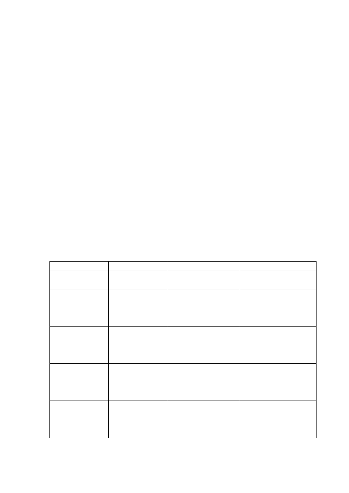
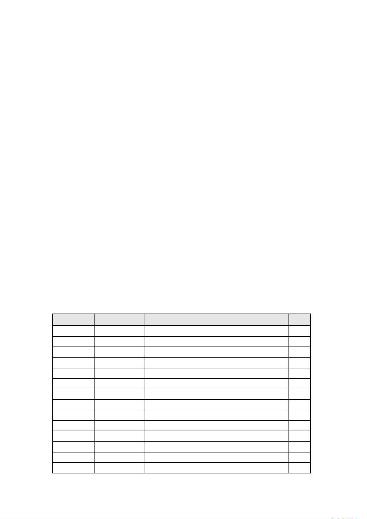
Ⅰ. Main ICs and components
Serial number Name model Main function
1 U4 MP1430DN-LF-Z
2 U8 PI5V330SQEX
3 U9 24LC21AT/SN
4 U23 24LC32AT/SN
5 U11 STV-8217
6 U15 TDA1517P
7 U14 AZ1117H-1.8TRE1
8 U13 AZ1117H-3.3TRE1
9 U19 TDA9886TS/V4
Video switch
EEPROM(save display
parameter information)
EEPROM(save user control
information)
Audio processor
Audio power amplifier
Low dropout voltage
regulator
Low dropout voltage
regulator
Analog signal
processor
Page 7

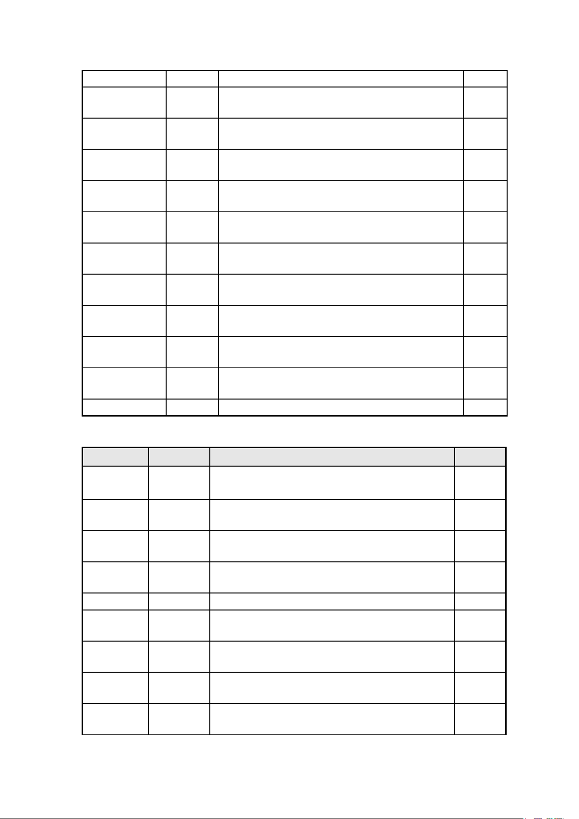
10 U17 TDA5-E2I21RW2
Video Decoder
Analog Input
Color Engine
RF tuner
11 U22 MST718BE-LF
AD converter and format
transformer
Ⅱ. The function introduction of main IC
1 The MST718BE is a high quality ASIC for NTSC/PAL/SECAM LCD-TV
application. It receives analog NTSC/PAL/SECAM CVBS and S-Video inputs
from TV tuners, DVD or VCR sources, including weak and distorted signals,
as well as analog RGB input from GPS systems. Automatic gain control (AGC)
and 10-bit 3-channel A/D converters provide high resolution video
quantization. With automatic video source and mode detection,users can
easily switch and adjust variety of signal sources. Multiple internal
adaptive PLLs precisely extract pixel clock from video source and perform
sharp color demodulation. Built-in line-buffer supports adaptive 2-D
comb-filter, 2-D sharpening, and synchronization stabler in a condense
manner. The output format of MST718BE supports 8-bit TTL or LVDS digital
TFT-LCD modules.
MST518 FEATURES:
● Supports NTSC, PAL and SECAM video input formats
●2D NTSC and PAL comb-filter for Y/C separation of CVBS input
●Multiple CVBS and S-video inputs Supports Closed-caption and V-chip
●Supports Teletext 1.5
●ACC, AGC, and DCGC (Digital Chroma GainControl)
●Supports RGB input format from PC,camcorders and GPS
●Supports YCbCr inputs from conventional videosource and HDTV
●Supports SCART – RGB + Fast Blank
●Supports video input 480i, 480p, 576i, 576p,720p, 1080i; RGB input
resolution in 640x480,800x480, 800x600, 1024x768, and
1280x1024(SXGA)
●3-channel low-power 10-bit ADCs integration for YCbCr and RGB
●Supports RGB composite sync input (CSYNC),SOY, SOG, HSYNC, and VSYNC
●On-chip clock synthesizer and PLL
●Auto-position adjustment, auto-phase adjustment, auto-gain
adjustment, and auto-mode detection
●Brightness, contrast, saturation, and hue adjustment
●9-tap programmable multi-purpose FIR (Finite Impulse Response)
filter
●Differential 3-band peaking engine
●Vertical peaking
●Spatial noise reduction
Page 8
●Luminance Transient Improvement (LTI)
Scaling Engine/Panel Interface
Miscellaneous
●Chrominance Transient Improvement (CTI)
●Black Level Extension (BLE)
●White Level Extension (WLE)
●Favor Color Compensation (FCC)
●3-channel gamma curve adjustment
●Independent 6 color of saturation, hue, and brightness control
●Supports digital panels up to 1366x768, and 1440x900
●Supports single/dual 8-bit LVDS panel outputs
●Supports 8-bit TTL panel output
●Supports various displaying modes
●Supports horizontal panorama scaling
●Built-in MCU
●3-wire serial bus interface for configuration setup
●Built-in step-down PWM circuits for input 2.5V
●Built-in internal OSD with 512 programmable fonts, 1、2 or 4 bit per
pixel color, 16-color palettes, and 12-bit color resolution
●Supports external OSD
●Support CVBS out
●Spread spectrum clocks
●Optional 3.3V / 5V output pads with programmable driving current
●128-pin PQFP package
MST718 pin function:
Analog Interface
Pin Name Pin Type Function Pin
VMID
VCLAMP
REFM
REFP
PRINP Analog Input Analog Pr Input of HDTV 7
PRINM Analog Input Reference Ground for Analog Pr Input o f HDTV 8
PBINP Analog Input Analog Pb Input of HDTV 9
PBINM Analog Input Reference Ground for Analog Pb Input of HDTV 10
SOY Analog Input Sync-on-Y slicer input 11
YINP Analog Input Analog Y Input of HDTV 12
YINM Analog Input Reference Ground for Analog Y Input of HDTV 13
BINP Analog Input Analog B Input of VGA 14
BINM Analog Input Reference Ground for Analog B Input of VGA 15
SOGIN Analog Input Sync-on-Green slicer input 16
Mid-Scale Voltage Bypass 2
CVBS/YC Mode Clamp Voltage Bypass 3
Internal ADC Bottom De-coupling Pin 4
Internal ADC Top De-coupling Pin 5
Page 9

GINP Analog Input Analog G Input of VGA 17
GINM Analog Input Reference Ground for Analog G Input of VGA 18
RINP Analog Input Analog R Input of VGA 19
RINM Analog Input Reference Ground for Analog R Input of VGA 20
C1INP Analog Input Analog Chroma Input for TV S-Video1 / Analog
Composite Input of TV CVBS4
C1INM Analog Input Reference Ground for Analog Chroma Input of TV
S-Video1 / Analog Composite Input of TV CVBS4
YS1INP Analog Input
YS1INM Analog Input Reference Ground for Analog Luma Input of TV
C2INP Analog Input Analog Chroma Input for TV S-Video2 26
C2INM Analog Input
YS2INP Analog Input Analog Luma Input of TV S-Video2 28
YS2INM Analog Input
CVBS1P Analog I nput Analog Composite Input for TV CVBS1 30
CVBS1M Analog Input
CVBS2P Analog I nput Analog Composite Input for TV CVBS2 32
CVBS2M Analog Input
Analog Luma Input o f TV S-Video1 / Analog
Composite Input of TV CVBS3
S-Video1 / Analog Composite Input of TV CVBS3
Reference Ground for Analog Chroma Input of TV
S-Video2
Reference Ground for Analog Luma Inp ut of TV
S-Video2
Reference Ground for Analog Composite Input of
TV CVBS1
Reference Ground for Analog Composite Input of
TV CVBS2
22
23
24
25
27
29
31
33
Pin Name Pin Type Function Pin
VREXT_CDAC Analog Input
HSYNCIN1 Schmitt Trigger Input
w/ 5V-tolerant
VSYNCIN1
HSYNCIN2 Schmitt Trigger Input
VSYNCIN2 Schmitt Trigger Input
Schmitt Trigger Input
w/ 5V-tolerant
w/ 5V-tolerant
w/ 5V-tolerant
Reference Current Generator, 820 ohm to
Ground
HSYNC / Composite Sync for VGA Input 1 125
VSYNC for VGA Input 1 124
HSYNC / Composite Sync for VGA Input 2 123
VSYNC for VGA Input 2 122
116
Digital Panel Output Interface
Pin Name Pin Type Function Pin
CLKO Output Display Clock Output 77
DEO Output Display Enable Output 78
VSYNCO Output Vertical Sync Output 79
Page 10
HSYNCO Output Horizontal Sync Output 80
BOUT[7]/LVB0M Output Blue channel Output [7] / LVDS B-Link Channel 0
Negative Differential Data Output
BOUT[6]/LVB0P Output Blue channel Output [6] / LVDS B-Link Channel 0
Positive Differential Data Output
BOUT[5]/LVB1M Output
BOUT[4]/LVB1P Output Blue channel Output [4] / LVDS B-Link Channel 1
BOUT[3]/LVB2M Output
BOUT[2]/LVB2P Output Blue channel Output [2] / LVDS B-Link Channel 2
BOUT[1]/LVBCK
M
BOUT[0]/LVBCK
P
GOUT[7]/LVB3M Output Gre en channel Output [7] / LVDS B-Link Channel 3
GOUT[6]/LVB3P Output
GOUT[5:4] Output Gree n channel Output [5:4] 97, 96
Output Blue channel Output [1] / LVDS B-Link Negative
Output
Blue channel Output [5] / LVDS B-Link Channel 1
Negative Differential Data Output
Positive Differential Data Output
Blue channel Output [3] / LVDS B-Link Channel 2
Negative Differential Data Output
Positive Differential Data Output
Differential Clock Output
Blue channel Output [0] / LVDS B-Link Positive
Differential Clock Output
Negative Differential Data Output
Green channel Output [6] / LVDS B-Link Channel 3
Positive Differential Data Output
108
107
106
105
104
103
102
101
99
98
Pin Name Pin Type Function Pin
GOUT[3]/LV
A0M
GOUT[2]/LV
A0P
GOUT[1]/LV
A1M
GOUT[0]/LV
A1P
ROUT[7:6] Output Red channel Output [7:6] 91, 90
ROUT[5]/LV
A2M
ROUT[4]/LV
A2P
ROUT[3]/LV
ACKM
ROUT[2]/LV
ACKP
Output
Output Green channel Output [2] / LVDS A-Link Channel 0
Output Green channel Output [1] / LVDS A-Link Channel 1
Output Green channel Output [0] / LVDS A-Link Channel 1
Output Red channel Output [5] / LVDS A-Link Chan nel 2
Output Red channel Output [4] / LVDS A-Link Chan nel 2
Output Red channel Output [3] / LVDS A-Link Negative
Output Red channel Output [2] / LVDS A-Link Positive
Green channel Output [3] / LVDS A-Link Channel 0
Negative Differential Data Output
Positive Differential Data Output
Negative Di fferential Data Output
Positive Differential Data Output
Negative Differential Data Output
Positive Differential Data Output
Differential Clock Output
Differential Clock Output
95
94
93
92
89
88
87
86
Page 11

ROUT[1]/LV
A3M
ROUT[0]/LV
A3P
Output Red channel Output [2] / LVDS A-Link Chan nel 3
Negative Differential Data Output
Output Red channel Output [0] / LVDS A-Link Channel 3
Positive Differential Data Output
85
84
External OSD Interface
Pin Name Pin Type Function Pin
OSDR/GPIO
_P30
OSDG/GPIO
_P31
OSDB/GPIO_
P32
FB/GPIO_P3
3
I/O w/
5V-tolerant
I/O w/
5V-tolerant
I/O w/
5V-tolerant
I/O w/
5V-tolerant
External OSD R-channel Input / General Purpose
Input/Output; 4mA driving strength
External OSD G-channel Input / General Purpose
Input/Output; 4mA driving strength
External OSD B-channel Input / General Purpose
Input/Output; 4mA driving strength
External Fast-Blank Input / General Purpose
Input/Output; 4mA driving strength
Switching Power and PWM Interface
73
74
75
76
Pin Name Pin Type Function Pin
PWMOUT2 Output Switching Pulse Output for DC-DC Converter 38
FB2 Analog Input Error Voltage Feedback Input Pin for PWM2;
voltage = 1.2V
SENSE2 Analog Input Sense Circuit Connection for PWM2 40
PWMOUT1 Output Switching Pulse Output for DC-DC Converter 41
FB1 Analog Input Error Voltage Feedback Input Pin for PWM1;
voltage = 1.2V
SENSE1 Analog Input Sense Circuit Connection for PWM1 43
PGOOD Output Power Good Indicator 44
39
42
Internal MCU Interface with Serial Flash Memory
Pin Name Pin Type Function Pin
SAR2 Analog Input SAR Low Speed ADC Input 2 49
SAR1 Analog Input SAR Low Speed ADC Input 1 48
SAR0 Analog Input SAR Low Speed ADC Input 0 47
Page 12

SCK Output SPI Interface Sampling Clock 52
SDI Output SPI Interface Data-In 53
SDO Input w/ 5V-tolerant SPI Interface Data-Out 54
CSN Output SPI Interface Chip Select 55
GPIO_P00-
GPIO_P07
INT Input Interrupt Input for IR Receiver 65
SDA I/O w/ 5V-tolerant 3-Wire Serial Bus Data 66
SCL Input w/ 5V-tolerant 3-Wire Serial Bus Clock 67
POWER_O
N_RSTN/C
S
I/O w/ 5V-tolerant General Purpose Input/Output; 4mA
driving strength
Input w/ 5V-tolerant
Power On Reset Sig nal/Chip Selection for
3-wire Serial
58-64, 83
68
Misc. Interface
Pin Name Pin Type Function Pin
RESET Schmitt Trigger
Input w/
5V-tolerant
XIN Analog Input Crystal Oscillator Input
XOUT Analog Output Crysta l Oscillator Output 120
GPIO_P24
/PWMD3
Output General Purpose Input/Output; 4mA driving
Hardware Reset; active high 72
121
56
strength/ Pulse Width Modulation Output;
4mA driving strength
Pin Name Pin Type Function Pin
GPIO_P25
/PWMD4
PWMD2 Output
PWMD1 Output
INT_OUT Output Mod e Detection Interrupt Output 100
CVBSO1
/CVBSO2
MCUSEL Input Embedded MCU selection.
Output General Purpose Input/Output;
4mA driving strength/ Pulse Width
Modulation Output; 4mA driving strength
Pulse Width Modulation Output;
4mA driving strength
Pulse Width Modulation Output;
4mA driving strength
Output
Analog Composite Output for
TV CVBS1/CVBS2
0: MCU on. 1: MCU off.
57
70
71
34, 115
109
Power Pins
Pin Name Pin Type Function Pin
Page 13

AVDD_ADC 2.5V Power ADC Power 6, 21
FEATURES
AVDD_GMC 5V Power GMC Power 35
AVDD_PWM 5V Power PWM Power 37
AVDD_OPLL 2.5V Power OPLL Power 113
AVDD_CDAC 2.5V Power Current DAC Power 117
AVDD_XTAL 5V Power XTAL Power 118
AVDD_MPLL 2.5V Power MPLL Power 127
VDDC 2.5V Power Digital Core Power 50, 110
VDDP 3.3V /5V Power Digital Input/Output Power 46, 82
GND Ground Ground 1, 36, 45, 51, 69, 81, 111,
112, 114, 119, 126, 128
2 TDA9886 introduction:
The TDA9885 is an alignment-free multistandard (PAL and NTSC) vision and
sound IF signal PLL demodulator for negative modulation only and
FM processing.The TDA9886 is an alignment-free multistandard (PAL, SECAM
and NTSC) vision and sound IF signal PLL demodulator for positive and
negative modulation,including sound AM and FM processing.
· 5 V supply voltage
· Gain controlled wide-band Vision Intermediate Frequency (VIF)
amplifier, AC-coupled
· Multistandard true synchronous demodulation with active carrier
regeneration: very linear demodulation,good intermodulation figures,
reduced harmonics, and excellent pulse response
· Gated phase detector for L and L-accent standard
· Fully integrated VIF Voltage Controlled Oscillator(VCO),
alignment-free, frequencies switchable for all negative and positive
modulated standards via I2C-bus
· Digital acquisition help, VIF frequencies of 33.4, 33.9,38.0, 38.9,
45.75, and 58.75 MHz
Page 14

· 4 MHz reference frequency input: signal from Phase-Locked Loop (PLL)
tuning system or operating as crystal oscillator
· VIF Automatic Gain Control (AGC) detector for gain control, operating
as peak sync detector for negative modulated signals and as a peak white
detector for positive modulated signals
· External AGC setting via pin OP1
· Precise fully digital Automatic Frequency Control (AFC) detector with
4-bit digital-to-analog converter, AFC bits readable via I2C-bus
· TakeOver Point (TOP) adjustable via I2C-bus or alternatively with
potentiometer
· Fully integrated sound carrier trap for 4.5, 5.5, 6.0, and 6.5 MHz,
controlled by FM-PLL oscillator
· Sound IF (SIF) input for single reference Quasi Split Sound (QSS) mode,
PLL controlled
· SIF-AGC for gain controlled SIF amplifier, single reference QSS mixer
able to operate in high performance single reference QSS mode and in
intercarrier mode, switchable via I2C-bus
· AM demodulator without extra reference circuit
· Alignment-free selective FM-PLL demodulator with high linearity and
low noise
· I2C-bus control for all functions
· I2C-bus transceiver with pin programmable Module Address (MAD)
· Four I2C-bus addresses via MAD.
TDA9886 pin function:
SYMBOL PIN DESCRIPTION
VIF1 1 VIF differential input 1
VIF2 2 VIF differential input 2
n.c. - not connected
OP1 3 output port 1; open-collector
FMPLL 4 FM-PLL for loop filter
DEEM 5 de-emphasis output for capacitor
AFD 6 AF decoupling input for capacitor
DGND 7 digital ground
n.c. - not connected
AUD 8 audio output
TOP 9 tuner AGC TakeOver Point (TOP) for resistor adjustment
SDA 10 I2C-bus data input and output
SCL 11 I2C-bus clock input
SIOMAD 12 sound intercarrier output and MAD select with resistor
n.c. - not connected
n.c. 13 not connected
Page 15

FEATURES
n.c. - not connected
TAGC 14 tuner AGC output
REF 15 4 MHz crystal or reference signal input
VAGC 16 VIF-AGC for capacitor
n.c. - not connected
CVBS 17 composite video output
n.c. - not connected
AGND 18 analog ground
VPLL 19 VIF-PLL for loop filter
VP 20 supply voltage
AFC 21 AFC output
OP2 22 output port 2; open-collector
n.c. - not connected
SIF1 23 SIF differential input 1 and MAD select with resistor
SIF2 24 SIF differential input 2 and MAD select with resistor
n.c. - not connected
n.c. - not connected
3 TDA1517 introduction:
The TDA1517 is an integrated class-B dual output amplifier in a plastic
single in-line medium power package with fin (SIL9MPF), a plastic
rectangular-bent single in-line medium power package with fin (RBS9MPF)
or a plastic heat-dissipating dual in-line package (HDIP18). The device
is primarily developed for multi-media applications.
· Requires very few external components
· High output power
· Fixed gain
· Good ripple rejection
· Mute/standby switch
· AC and DC short-circuit safe to ground and VP
· Thermally protected
· Reverse polarity safe
· Capability to handle high energy on outputs (VP = 0 V)
· No switch-on/switch-off plop
· Electrostatic discharge protection.
Page 16

TDA1517 pin function:
SYMBOL
PIN DESCRIPTION
-INV1
non-inverting input 1
SGND
2 signal ground
SVRR
3 supply voltage ripple
rejection output
OUT1
4 output 1
PGND
5 power ground
OUT2
6 output 2
VP 7 supply voltage
M/SS
8 mute/standby switch
input
-INV2
9 non-inverting input 2
Pin
symbol
function
1
PartⅢ: Signal Processing Flow chart
This chapter mainly introduces analog signals process、video intensify
process、TV system control process、TV supply system.
Ⅰ. analog signals process
1、 IF/RF process
Completed by TAF5-E2I21RW2 RF tuner, output IF signal.
The Function of RF tuner is below:
1 AGC Auto gain control voltage
2 TU The TV do not connect
3 ADD ground
4 SCL
5 SDA
6 BM +5V power supply
7 BM +5V power supply
I2C bus(clock )
I2C bus(data )
Page 17

8 NC Not connected
9 BTL
10 NC Not connected
11 IF IF signal output
+32V power supply,form 0~32V tune
voltage
2、 Image and sound process
TDA9886 chip receives the IF signal separated from SAW filter, detects
and decodes. Output CVBS analog signals from the 17 pin. Output the main
channel L/R audio signal from 8 pin. CVBS analog signals is decoded
inside of MST718BE chip. L/R audio signal is decoded inside of STV82x7
chip,then output the main channel L、R audio signal from 28、29 pin.
Moreover, AV、SCART、YC signal of inside DVD(some types of TV have
not) is decoded inside of P15V330 chip, switched with TV input in P15V330
and output one way RGB color analog signal, send it to back-end process.
3、 Digital signal process
The analog RGB signal output from UOC and RGB signal output from DFP
are switched and selected by a PI5V330A,input it into the 65、63、60 pin
Of MST518. The RGB signal output from computer and HD-YPbPr signal are
switched and selected by another PI5V330A,input into the 75、72、70 of
MST518.This two channel RGB signal are switched inside MST518,then AD
conversion, video format transition, at last output digital color signal
which is suitable for TFT drive circuit. MST518 finishes the pixels ratio
converting of input video signal、the image auto optimization
process ,then process via memory buffer、scaler、chroma matrix circuit、
chroma look-up table、chroma space gain, etc. Output corresponding
standard physical resolution digital color signal and corresponding
sync, clock signal to TFT, control the TFT to display image correctly.
4、TV power supply system:
(1) The supply power system of the main IC is below:
● 12Vcc:the unit main power supply
● +34V:RF tuner tune voltage
● VCC5: stable and constant +5V power supply
● VCC5A: +5V power supply software can turn off
● V3_3D:UOC digital part supply power supply
● V1_8V1:UOC digital part constant supply power supply
● V1_8V2:UOC digital part power supply can be turned off
● V2_5M:MST518 digital core supply power supply
● V3_3M:MST518 supply power supply
(2) The constitution and distributing of the TV
Page 18

5、The location of main components and socket on mainboard and definition
Page 19

Page 20

Socket definition
NO.
Name
Connect object
Function description
1
Connect outside SCART signal input
2
Connect outside HD audio input
3
4
5
audio input
6
Connect adapter outside power
7
8
9
Connect display screen
10
MST718 debug socket
Not used
11
12
13
14
15
16
switch,GND, GND,GND
No.
Name
Element
Function description
IF Filter for Video Applications
IF Filter for Audio Applications
Serial Flash Memory
Liner voltage IC
Connect outside HD-YPbPr input
Connect outside VGA input
Connect outside VGA
Connect inside supply power board
module
Connect display screen
Connect remote control
receiving board
Connect TV K board
Connect speaker
Connect speaker
Connect earphone output
board
Connect inverter
Look circuit diagram,the
fifth pin is 3.3V
Look circuit diagram ,the
second pin is 3.3V
+12V, +12V, backlight
Description of Main component
A U17
TDA5-E2I21RW2
B U11 STV82x7 Audio processor
C U14 Ams1117-1.8
E U15 TDA1517
F U20 K3953M
G U18 K9656M
H U19 TDA9886 Analog signal processor
I U8 P15V330
G U13 Ams1117-3.3
K U2 7808
L U22 MST718BE
M U9 24C21
N U24 PS25LV040
O U23 24C32
P U4 MSP1430
RF input, IF output
Low dropout voltage regulator
Audio power amplifier
Video switch
Low dropout voltage regulator
THREE TERMINAL POSITIVE VOLTAGE REGULATORS
AD converter and format transformer
EEPROM(save display parameter information)
EEPROM(save display parameter information)
Page 21

Q U7 Ams1117-2.5
R U6 Ams1117-3.3
S U5 4435(9435)
T U1 IRF7314
Low dropout voltage regulator
Low dropout voltage regulator
ARX4435 Transceiver for Macair H009 Specificat ion
HEXFET Power MOSFET
Page 22

D
D:\lzy\ \ls07\ \Phase5_2004_1018_1022\LS07_MPCB_PH5_CHN_for_MP_20041029.DDB设计文件 设计文件
C
B
A
03_TUNER
03_TUNER
IF_OUT
+34V
SCL_UOC
SDA_UOC
AGC
02_AV_PC_HD
02_AV_PC_HD
HD_AUD_LIN
PC_RIN
PC_GIN
PC_BIN
HD_AUD_RIN
PC_AUD_LIN
PC_AUD_RIN
PR_IN
PB_IN
HD_Y_IN
TV_IR
LED_RED
LED_GREEN
TV_KEY_DEC
SDA_UOC
SCL_UOC
PC_VS
PC_HS
HD_Y_IN
PB_IN
PR_IN
HD_PC_SW
SOGIN1
PC_RIN
PC_GIN
PC_BIN
PC_HS
PC_VS
PC_HSIN
PC_VSIN
HD_PC_SW
DVD_KEY_DEC
DVD_C2IN
DVD_Y2IN
DVD_AUD_LIN
DVD_AUD_RIN
SVIDEO_C1IN
SVIDEO_Y1IN
AV_CVBSIN
AV_AUD_LIN
AV_AUD_RIN
UPDATE_CON
VGA_SDA
DDC_SDA
DDC_SCL
VGA_SCL
10_VGA_UPDATE
10_VGA_UPDATE
UPDATE_CON
VGA_SCL
VGA_SDA
DDC_SDA
DDC_SCL
SCL_UOC
SDA_UOC
1 2 3 4 5 6
G_RIN
G_GIN
G_BIN
04_UOCIII TDA15063H
04_UOCIII TDA15063H
AV_CVBSIN
Y_OUT
U_OUT
V_OUT
TV_R
TV_G
TV_B
TV_HSYNC
SANDC
AGC
M_LOUT
M_ROUT
HP_LOUT
HP_ROUT
TV_IR
LED_GREEN
LED_RED
TV_KEY_DEC
IF_OUT
SDA_UOC
SCL_UOC
PC_AUD_LIN
V_IN
U_IN
Y_IN
HD_PC_SW
CSZ_MST
SDA_MST
SCL_MST
RST_MST
ASTB
SCL_DPF
AV_AUD_LIN
AV_AUD_RIN
HD_AUD_LIN
HD_AUD_RIN
SDA_DPF
PC_AUD_RIN
SCL_UOC
SDA_UOC
ON_PANEL
ON_BACKLITE
DVD_KEY_DEC
HP_IDENT
INT_MST
TV_DPF_SW
PWRON
DVD_C2IN
DVD_Y2IN
DVD_AUD_LIN
DVD_AUD_RIN
EN_DPF_DVD
MUTE
TV_VSYNC
SVIDEO_Y1IN
SVIDEO_C1IN
05_TV_DPF_MUX
05_TV_DPF_MUX
SANDC
V_IN
V_OUT
Y_IN
U_OUT
U_IN
Y_OUT
SDA_UOC
SCL_UOC
TV_HSYNC
TV_DPF_VSIN
TV_DPF_HSIN
TV_B
TV_R
TV_G
DPF_RIN
DPF_GIN
DPF_BIN
TV_DPF_SW
TV_DPF_SW
DPF_RIN
DPF_GIN
DPF_BIN
TV_VSYNC
TV_DPF_RIN
TV_DPF_GIN
TV_DPF_BIN
06_MST518
06_MST518
TV_DPF_HSIN
TV_DPF_VSIN
PC_HSIN
PC_VSIN
TV_DPF_BINM
TV_DPF_BIN
TV_DPF_GINM
TV_DPF_GIN
TV_DPF_RINM
TV_DPF_RIN
SOGIN1
G_RIN
G_GIN
G_BIN
G_RM
G_GM
G_BM
SDA_MST
SCL_MST
CSZ_MST
RST_MST
INT_MST
RB[0..7]
GB[0..7]
BB[0..7]
PCLK
PDEN
PHSYNC
PVSYNC
RX0+
RX0RXCLKRXCLK+
RX1RX1+
RX2RX2+
RX3RX3+
TV_DPF_RINM
TV_DPF_GINM
TV_DPF_BINM
G_RM
G_GM
G_BM
SDA_MST
SCL_MST
CSZ_MST
RST_MST
08_Sound Amplifier
08_Sound Amplifier
HP_ROUT
HP_LOUT
HP_IDENT
M_LOUT
M_ROUT
ASTB
MUTE
07_Panel
07_Panel
BB[0..7]
PCLK
PHSYNC
RB[0..7]
PVSYNC
GB[0..7]
PDEN
RX0+
RX0RXCLKRXCLK+
RX1RX1+
RX2RX2+
RX3RX3+
09_Power Supply
09_Power Supply
+34V
PWRON
ON_PANEL
ON_BACKLITE
EN_DPF_DVD
SDA_DPF
SCL_DPF
Title
Number RevisionSize
B
Date: 5-Apr-2005 Sheet of
File:
VLCD
LS07-CHN-LCDTV
1
Drawn By:
654321
D
C
B
A
Ver 5.0
Page 23

D:\lzy\ \ls07\ \Phase5_2004_1018_1022\LS07_MPCB_PH5_CHN_for_MP_20041029.DDB设计文件 设计文件
1-788624-2/AMP
2
1
J1
D5
3
BAV99
6
1
11
7
2
12
8
3
13
9
4
14
10
5
15
16 17
VCC5
2
1
DDC_SCL
DDC_SDA
J5
5
4
3
2
1
CON5
J6
3
2
1
CON3
J7
3
2
1
CON3
PR_IN
PC_RIN
HD_Y_IN
PC_GIN
PB_IN
PC_BIN
HD_PC_SW
0: Select YPbPr
1: Select PC
D4
BAV99
3
VRIN
VGIN
VGA_SDA
VBIN
VGA_V
UPDATE_CON
VGA_SCL
PC_VS
ECBP2012M801T C12 220pF
PC_HS
FB4
ECBP2012M801T
VGA_V
2
BAV99
1
V3_3D
TV_IR
LED_GREEN
LED_RED
V3_3D
R29
47K
V3_3D
R20
47K
2
3
5
6
14
13
11
10
1
15
2
3
D1
BAV99
1
FB5
C12,C13 option (open for better phase)
2
3
D7
TV_KEY_DEC
DVD_KEY_DEC
S1A
S2A
S1B
S2B
S1C
S2C
S1D
S2D
IN
/EN
PI5V330A
D8
BAV99
1
U6
16
VCC
4
DA
7
DB
12
DC
9
DD
8
GND
2
3
D2
BAV99
1
R22 1K
R21 10K
R23 1K
C13 33pF
R24 2.2K
R41 Option
3
J11
4
3
2
CON4
Use for WISP and WIC32
VCC5
2
3
D3
BAV99
1
R42
R45
R43
10K
15K
15K
SDA_UOC
R16
10
SCL_UOC1
ECB2012M800T VCC5A
C120
0.1uF
R152
100
100R153
R154 100
R155 390 C133 1nF
ECBP2012M700T
ECBP2012M700T
ECBP2012M700T
PC_VS
PC_HS
7
6
5
VCC5
FB38
C121
10uF16V
C124 47nF
C122
FB3
FB2
FB1
U1
VCLK
SCL
SDA
24LC21A
47nF
47nFC123
C125
0.1uF
VGA_PWR
R1
75
VCC
NC1
NC2
NC3
GND
R2
C1
12pF
75
2 1
8
1
2
3
4
G_RIN
G_GIN
G_BIN
SOGIN1
C2
12pF
D6 BAV70
3
C20
0.1uF
VCC5
R3
75
C3
12pF
AV-1-3PKF
J3B
AV-1-3PKF
J3C
AV-1-3PKF
HD_PC_SW
PC_HS
PC_VS
13 U16D
PC_RIN
PC_GIN
PC_BIN
J3A
Y
ECBP2012M700T
4
PB
ECBP2012M700T
5
PR
6
74LVC126A
3 2
FB51
1
FB52
2
FB53
3
ECBP2012M700T
1112
J2
D-S-06
R219
1
4
75
R218
R217
75
75
14
C24
10uF16V
C21
10uF16V
C14
10uF16V
V3_3M
FB49 ECI2012M2R2KT
C6
270pF
FB57 ECI2012M2R2KT
C10
330pF
VCC5A
R178
22K
R56
10K
VCC5A
R179
22K
R48
10K
VCC5A
R180
22K
R26
10K
U16A
147
32
74LVC126A
U16B
65
74LVC126A
10 U16C
HD_Y_IN
PB_IN
PR_IN
89
74LVC126A
PC_HSIN
PC_VSIN
C7
270pF
C11
330pF
J20A
1
AV-1-3PKE
4
R34
47K
R51 1K
R52
5
J20B
AV-1-3PKE
6
J20C
AV-1-3PKE
7
C15
100pF
1K
2
3
SVIDEO_Y1IN
R7
75
SVIDEO_C1IN
R8
75
J4A
AV-1-2PKA
R32
1
1K
4
J8
GCC02-0085
FB58 ECI2012M2R2KT
C8
270pF
R10
R11
HD_AUD_LIN
R53
C22
47K
100pF
R54
C23
47K
100pF
FB21 ECI2012M2R2KT
C182
330pF
10K
10K
C9
270pF
R12
47K
R13
47K
3
PC_AUD_LIN
PC_AUD_RIN
C183
330pF
C17
100pF
C18
100pF
J4B
AV-1-2PKA
5
R50
75
R9
75
R33
2
1K
AV_CVBSIN
AV_AUD_LIN
AV_AUD_RIN
R35
47K
DVD_C2IN
C16
100pF
HD_AUD_RIN
DVD Signal Input
J9
CON12
J21
CON7
1
2
3
4
5
6
7
8
9
10
11
12
1
2
3
4
5
6
7
FB25 ECI2012M2R2KT
C184
270pF
C185
270pF
R25 10K
R27
10K
Title
B
Date: 5-Apr-2005 Sheet of
File:
R55
75
R44
C135
47K
100pF
R46
C146
47K
100pF
LS07-CHN-CONNECTORS
Number RevisionSize
2
DVD_Y2IN
DVD_AUD_LIN
DVD_AUD_RIN
Ver 5.0
Drawn By:
Page 24

654321
D:\lzy\ \ls07\ \Phase5_2004_1018_1022\LS07_MPCB_PH5_CHN_for_MP_20041029.DDB设计文件 设计文件
D
A1 TAF5-C2IP1RW
12
PAD
13
PAD
14
PHILIPS
AGC1TU2ADD3SCL4SDA5+5V6+5V7NC8BTL9NC10IF-OUT
C
R60 100
R61 100
R112 10K
R113 10K
D10
IN4148
C239
22uF16V
0.1uF
C147
FB35 ECB2012M800T
C240
47uF16V
AGC
SCL_UOC
SDA_UOC
AGC
R111
68K
SCL_UOC
SDA_UOC
B
PAD
15
PAD
R105
4.7K
11
C204
10nF
R47
100
C241
47uF16V
VCC5A
C148
0.1uF
C242
0.1uF
IFGND
R41
3.3K
D11
uPC574
R109
0
R110
100
C244
4.7uF/50V
L2
ECI2012KR56KB
Q1
2SC388
L5
ECI2012K220T
C209
10nF
C221
10nF
C224
22nF
R49
10
100uF16V
C227
IF_OUT
+34V
ECI2012K220T
IFGND
VCC5A
FB32
D
C
B
A
Title
LS07-CHN-TUNER
Number RevisionSize
B
Date: 5-Apr-2005 Sheet of
1 2 3 4 5 6
File:
3
Drawn By:
A
Ver 5.0
Page 25

D
D:\lzy\ \ls07\ \Phase5_2004_1018_1022\LS07_MPCB_PH5_CHN_for_MP_20041029.DDB设计文件 设计文件
C
B
A
FB50
AV_CVBSIN
DVD_Y2IN
SVIDEO_Y1IN
DVD_C2IN
SVIDEO_C1IN
PC_AUD_LIN
PC_AUD_RIN
DVD_AUD_LIN
DVD_AUD_RIN
HD_AUD_LIN
HD_AUD_RIN
AV_AUD_LIN
AV_AUD_RIN
C53
10uF16V
C86
1uF/50V
U2B
78
V_IN
U_IN
Y_IN
Y_OUT
R91 12K
C87
47uF16V
IFGND
R63 Option
UOC_VIFIN1
UOC_VIFIN2
UOC_SIF1
UOC_SIF2
VDD5A_1
R73 47K
C55 2.2uF
C56 2.2uF
R74 4.7K
C54
0.1uF
C88
6.8nF
C90
0.1uF
C26 0.1uF
C149 0.1uF
C4 0.1uF
C5 0.1uF
C57 2.2uF
C245 2.2uF
C58 220nF
C59 2.2uF
C60 2.2uF
TV_VSYNC
R76 39K
C89 330nF
C29 0.1uF
C30 0.1uF
C31 0.1uFR63 0
C32 0.1uF
C150 0.1uF
C61 2.2uF
C246 2.2uF
MUTE
R93 100K
IFGND
R94 1K
C91 4.7uF
C92 3.3nF
79
80
77
70
71
72
73
55
58
51
59
52
48
24
25
29
30
53
54
56
57
21
19
49
50
34
35
33
23
22
20
27
26
32
28
17
16
38
39
91
13
R3/Pr
G3/Y
B3/Pb
FBLIN
V/R2/Pr
U/B2/Pb
Y/G2/Y
YSYNC
CVBS2/Y2
CVBS3/Y3
CVBS4/Y4
C2/C3
C4
SVO/CVBSI
VIFIN1
VIFIN2
SIF1
SIF2
AUDIO2_INL
AUDIO2_INR
AUDIO3_INL
AUDIO3_INR
EWD/AVI
SECPLL
AUDIO4_INL
AUDIO4_INR
AUDIO5_INL
AUDIO5_INR
SSIF
VDRA
VDRB
DECBG
IREF
VSC
EHT
GNDIF
PH1LF
PH2LF
DECSDEM
QSSO
REFAD
VGUARD
UOUT/INSSW2
VOUT/SWO1
AUDOUTSL
AUDOUTSR
AUDIO_OUT_LSL
AUDIO_OUT_LSR
AUDIO_OUT_HPL
AUDIO_OUT_HPR
P00/I2SDI1/0
P01/I2SDO1
P02/I2SDO2
YOUT
CVBSO/PIP
ROUT
GOUT
BOUT
BCLIN
BLKIN
SVM
FBISO
HOUT
AGC
IFVO
FMRO
PLLIF
SIFAGC
AGC2SIF
INT0
P03/I2SCLK
P04/I2SWS
P10/INT1
P11/T0
P12/INT2
P13/T1
P14/RX
P15/TX
P16/SCL
P17/SDA
P20/TPWM
P21/PWM0
P22/PWM1
P23/PWM2
P24/PWM3
P25/PWM4
P30/ADC0
P31/ADC1
P32/ADC2
P33/ADC3
74
75
76
64
85
86
87
C33 4.7uF/50V
83
84
65
66
67
31
43
44
41
42
46
36
37
60
61
62
63
97
106
105
104
103
102
98
99
126
R233 100
107
127
128
R98 100
108
R99 100
109
R97
111
R100
112
113
R234
114
R96
122
R235 100
123
R236
115
116
R101
119
R238 100
R95 100
120
R67 100
R68 100
R69 100
R70 100
R71 27K
R66 2.7K
R72 680
R77 390
C62 1uF/50V
C63 1uF/50V
R227
R228
R80 100
R81 100
R82 100
R114
R229
R230
R231
R232 100
TDA15063H_2
T1
K7262D
R125
10K
1
2
1
2
R126 10K
T2
SAW
IFGND
SAW
IFGND
3
3
IF_OUT
R120
R118
1K
2.2K
VCC5A V1_8V2
FB43
IFGND
R119 2.2K
D9
BA792
C103
10nF
IFGND
Q7
2N3904
C34 1nF
C35 10nF
100
100
100
100
100
100
K9352D
Y_OUT
VCC5A
C64 0.1uF
100
100
100
100
100
100
R212 100
R213
R214
R215
R216 100
R103 10K
R104 10K
4
5
4
5
100
R1833.3K
M_LOUT
M_ROUT
HP_LOUT
HP_ROUT
R1073.3K
R1023.3K
R1063.3K
100
100
SAW_SW
VCC5
Y_OUT
U_OUT
V_OUT
SANDC
TV_HSYNC
AGC
C98220pF
VCC5
UOC_VIFIN1
UOC_VIFIN2
UOC_SIF1
UOC_SIF2
SAW_SW
TV_R
TV_G
TV_B
V3_3D
R2103.3K
R1163.3K
R1173.3K
R1153.3K
SCL_UOC
SDA_UOC
LED_RED
LED_GREEN
ON_PANEL
EN_DPF_DVD
ON_BACKLITE
HP_IDENT
DVD_KEY_DEC
TV_KEY_DEC
R833.3K
R84
3.3K
R853.3K
VCC5
R873.3K
R863.3K
SCL_UOC
SDA_UOC
R883.3K
R246
0
R893.3K
VCC5
R903.3K
IFGNDIFGND
1 2 3 4
TV_IR
PWRON
TV_DPF_SW
ASTB
HD_PC_SW
RST_MST
SCL_DPF
SDA_DPF
INT_MST
CSZ_MST
SDA_MST
SCL_MST
V3_3D
6
5
3
2
1
VCC5A
V1_8V1
SCL
SDA
A2
A1
A0
U4
VCC
GND
24LC32A
V3_3D
C94
0.1uF
WP
C36
0.1uF
C37
0.1uF
C38
0.1uF
C67
0.1uF
C68
0.1uF
C69
0.1uF
C70
0.1uF
U2A
0.1uF
VDD5A_1
15
C42
0.1uF
VDD5A_2
C43
0.1uF
C44
0.1uF
C75
0.1uF
C76
VDD5A_1
18
GNDA1
47
VDD5A_2
40
GNDA2
82
VDD5A_3
81
GNDA3
1
GNDA
4
VDD3A
12
GNDA
88
VDD3
220nF
110
C77
VDDP
0.1uF
118
V1_8DIG
C78
0.1uF
C97
5
6
7
8
9
VDD18
VREF_SDAC1
GREF_SDAC1
VREF_SDAC2
GREF_SDAC2
VREF_SDAC3
VDDC
VDDC
VDDC
VSSC
VSSC
VSSC
VREF
VSS_REF
VCOMB
VSSCOMB
VADC
VSSADC
VDDA
GNDAUD
VDDC
VDD3A
VSSC
V8SWTCH
DECDIG
XOUT
124
100
117
101
121
125
90
89
69
68
96
95
93
92
3
94
2
45
14
10
XIN
11
FB8
C39
47uF16V
FB9
C40
47uF16V
FB10
C41
10uF16V
FB13
FB14
C72
10uF16V
FB15
C73
10uF16V
FB16
C74
10uF16V
FB20
C96
100uF16V
TDA15063H_1
4
4
V3_3D
C100
VCC5
8
C95
4
0.1uF
7
0.1uF
DECDIG
C247
100uF16V
C107
220nF
FB42
VCC5
C106
47uF16V
R129
10K
C151
0.1uF
GND1OUT2VIN
3
R243 10K
U22
NCP1117DT18RK
2N3904
Title
B
Date: 5-Apr-2005 Sheet of
File:
4321
C47
680nF
C45
680nF
R211
10
680nF
V3_3D
C49
C48
220nF
VCC5A
FB12
C46
0.1uF
C79
220nF
C51
100uF16V
FB18
V1_8V2
C82
0.1uF
FB19
C80
220nF
FB17
C81
0.1uF
V1_8V1
C85
100uF16V
DECDIG
FB56
C83
0.1uF
V3_3D
C84
0.1uF
VDD5A_2
Y1
33pF
C99
24.576M
C101
33pF
Select Y2 - Saronix 9922 520 20264
V1_8V1
C248
C152
100uF16V
0.1uF
Q9
Si2311DS
Q26
LS07-CHN-UOCIII TAD12021H
Number RevisionSize
4
Drawn By:
V1_8V1
C52
100uF16V
D
V1_8V2
C
B
A
Ver 5.0
2
Page 26

4321
D:\lzy\ \ls07\ \Phase5_2004_1018_1022\LS07_MPCB_PH5_CHN_for_MP_20041029.DDB设计文件 设计文件
4
IN1GND2OUT
6
8
9
1
14
11
3
4
5
4
3
U7
YIN
UIN
VIN
SC
SDA
SCL
ADCEXT1
ADCEXT2
ADCEXT3
TDA9178T
U17
MC78M08CDT
C114
100uF16V
VCC
YOU
UOUT
VOUT
DECDIG
ADR
TP
VEE
NC
NC
NC
TV_DPF_VSIN
TV_DPF_HSIN
C115
0.1uF
20
19
17
16
C119
15
7
0.1uF
10
18
2
23
24
Y_INU_OUT
U_IN
V_IN
D
C
B
A
VCC5A
FB37 ECB2012M800T
C153
D
ECBP2012M750T
DPF_RIN
DPF_GIN
DPF_BIN
C
TV_R
TV_G
B
TV_B
A
FB6
ECBP2012M750T
FB7
ECBP2012M750T
FB11
VCC5A
FB44 ECB2012M800T
C108 10uF16V
C250
22pF
C116 10uF16V
C251
22pF
C117 10uF16V
C252
22pF
R4
75
R130
4.7K
R131
10K
R137
4.7K
R138
10K
R139
4.7K
R148
10K
C93
12pF
R5
75
Q12
2N3904
R133
470
Q14
2N3904
R141
470
Q15
2N3904
R150
470
10uF16V
R6
C102
12pF
75
C238
R134
FB45 ECI2012M2R4KT
75
C253
470pF
R142
FB46 ECI2012M2R4KT
75
C255
470pF
R151
75
FB47 ECI2012M2R4KT
C257
470pF
C237
0.1uF
C254
470pF
C256
470pF
C258
470pF
0.1uF
C105
12pF
R239 75
R240 75
R241
75
C249
10uF16V
C154
0.1uF
16
U20
2
S1A
3
S2A
VCC
R57
4
DA
5
S1B
6
S2B
14
S1C
13
S2C
11
S1D
10
S2D
1
IN
15
/EN
7
DB
12
DC
9
DD
GND
PI5V330A
8
R58 100
R59 100
100
C234 47nF
C235 47nF
C236 47nF
TV_DPF_SW
TV_DPF_RIN
TV_DPF_GIN
TV_DPF_BIN
0: Select TV
1: Select DPF
DPF Signal Input
J10
13
12
11
CON13
10
9
8
7
6
5
4
3
2
1
TV_DPF_SW
DPF_BIN
DPF_GIN
DPF_RIN
DPF_VSIN
DPF_HSIN
R15
3.3K
FB54
ECBP2012M801T C264 220pF
C264,C265 option (open for better phase)
FB55
ECBP2012M801T
V3_3M
R14
10K
Q2
2N3904
R140 1K
R132 10K
R149 1K
C265 33pF
R182 2.2K
TV_VSYNC
TV_HSYNC
1
10
4 U10B
13 U10D
74LVC126A
12Va
V3_3M
147
FB23
C112
100uF16V
U10A
32
74LVC126A
U10C
89
74LVC126A
65
74LVC126A
1112
Y_OUT
V_OUT
SANDC
SDA_UOC
SCL_UOC
R145 100
R146 100
R147 100
C113
0.1uF
R122 75
R121 75
Title
LS07-CHN-MUX/AUDIO AMP/TDA9178
Number RevisionSize
B
Date: 5-Apr-2005 Sheet of
1 2 3 4
File:
5
Drawn By:
Ver 5.0
Page 27

654321
D:\lzy\ \ls07\ \Phase5_2004_1018_1022\LS07_MPCB_PH5_CHN_for_MP_20041029.DDB设计文件 设计文件
D
C
B
A
VDPLL
VPLL VPO
VAD
48
56
54
J15
6
5
4
3
2
1
CON6
Only for Debug
C263
C143
0.1uF
0.1uF
C142
0.1uF
R123 0
Option: C263 and R123
CSZ_MST
SCL_MST
SDA_MST
RST_MST
VCC5
G_RIN
G_RM
G_GIN
G_GM
SOGIN1
G_BIN
G_BM
PC_HSIN
PC_VSIN
TV_DPF_RIN
TV_DPF_RINM
TV_DPF_GIN
TV_DPF_GINM
TV_DPF_BIN
TV_DPF_BINM
TV_DPF_HSIN
TV_DPF_VSIN
VAD
CSZ_MST
SCL_MST
SDA_MST
RST_MST
INT_MST
R175 390
R124 10K
C144 22pF
75
74
72
71
73
70
69
38
39
30
29
65
66
63
64
62
60
61
40
41
79
78
80
55
125
82
84
83
33
85
91
92
93
94
95
96
97
98
31
32
86
87
34
U3
AVDD
RIN0
RIN0M
GIN0
GIN0M
SOGIN0
BIN0
BIN0M
HSYNC0
VSYNC0
DDC_CLK
DDC_DAT
RIN1
RIN1M
GIN1
GIN1M
SOGIN1
BIN1
BIN1M
HSYNC1
VSYNC1
REFP
RMID
REFM
REXT
BUSTYPE
ALE/CSZ
RDZ/MST_SCL
WRZ/MST_SDA
HWRESETZ
INT
AD0
AD1
AD2
AD3
AD4
AD5
AD6
AD7
DDCROM_CLK
DDCROM_DAT
PWM0
PWM1
XIN
58
AVDD
AVDD
77
36
AVDD
AVDD_PLL
AVDD_MPLL
111
129
VDDP88VDDP99VDDP
MST518
139
VDDP
VDDP
Y2
14.318MHZ
C145 22pF
C262 0.1uF
35
XOUT
2
BYPASS
GND1GND
GND21GND
GND20GND42GND45GND51GND57GND76GND81GND89GND
9
GND
37
59
1 2 3 4 5 6
151
22
VDDP
VDDP10VDDC
VDDP
GND
100
101
112
VDD
102
114
142
VDDC
RA0/LVACKP
RA1/LVACKM
RA2/LVA2P
RA3/LVA2M
RA4/LVA1P
RA5/LVA1M
RA6/LVA0P
RA7/LVA0M
GA6/LVA3P
GA7/LVA3M
OCLK/LVBCKP
LDE/LVBCKM
LHS/LVB3P
LVS/LVB3M
BB0/LVB2P
BB1/LVB2M
BB2/LVB1P
BB3/LVB1M
BB4/LVB0P
BB5/LVB0M
GND
GND
113
130
19
VDDC
VDDC
GND
GND
140
141
GND
152
GA0
GA1
GA2
GA3
GA4
GA5
BA0
BA1
BA2
BA3
BA4
BA5
BA6
BA7
RB0
RB1
RB2
RB3
RB4
RB5
RB6
RB7
GB0
GB1
GB2
GB3
GB4
GB5
GB6
GB7
BB6
BB7
GND
V3_3M
ECBP2012M801T
131
RA0
132
RA1
133
RA2
134
RA3
135
RA4
136
RA5
137
RA6
138
RA7
115
116
117
118
119
120
127
GA6
128
GA7
103
104
105
106
107
108
109
110
145
146
143
144
RB0
15
RB1
16
RB2
17
RB3
18
23
RB4
RB5
24
RB6
25
RB7
26
GB0
5
GB1
6
GB2
7
GB3
8
GB4
11
GB5
12
13
GB6
GB7
14
BB0
147
BB1
148
BB2
149
BB3
150
BB4
153
BB5
154
BB6
3
BB7
4
RB[0..7]
GB[0..7]
BB[0..7]
RXCLK+
RXCLK-
RX2+
RX2-
RX1+
RX1-
RX0+
RX0-
RX3+
RX3-
PCLK
PDEN
PHSYNC
PVSYNC
RB[0..7]
GB[0..7]
BB[0..7]
R186
100
R187
100
R188
100
C156
C157
C158
47nF
47nF
47nF
V2_5M
ECBP2012M801T
V3_3M
ECBP2012M801T
V3_3M VPLL
ECBP2012M801T
V3_3M
ECBP2012M801T
TV_DPF_RINM
TV_DPF_GINM
TV_DPF_BINM
Title
Orcad B
Date: 5-Apr-2005 Sheet of
File:
FB26
FB30
FB27
FB28
FB29
10uF16V
10uF16V
10uF16V
10uF16V
Number RevisionSize
VPO
VDD
VAD
C162
C170
C175
C178
C163
0.1uF
C171
0.1uF
C176
0.1uF
C179
0.1uF
10uF16V
R189
100
R190
100
R191
100
C164
C165
0.1uF
0.1uF
C172
C173
0.1uF
0.1uF
C177
C260
0.1uF
0.1uF
VDPLL
C181
C180
0.1uF
C159
47nF
C160
47nF
C161
47nF
LS07-CHN-MST518
6
C166
0.1uF
C174
0.1uF
C261
0.1uF
C167
0.1uF
Drawn By:
C168
0.1uF
G_RM
G_GM
G_BM
C169
0.1uF
C259
0.1uF
D
C
B
A
Ver 5.0
Page 28

D
D:\lzy\ \ls07\ \Phase5_2004_1018_1022\LS07_MPCB_PH5_CHN_for_MP_20041029.DDB设计文件 设计文件
C
B
A
VLCD
J22
DP13-40DP-1.25V
123456789
10111213141516171819202122232425262728293031323334353637383940
VLCD
PDEO
RX0-
RX0+
RX1-
RX1+
RX2-
RX2+
RXCLK-
RXCLK+
RX3-
RX3+
R143
RA7
RA6
RA5
RA4
RA3
RA2
RA1
RA0
GA7
GA6
J16
1
VCC
2
VCC
3
GND
4
GND
5
RxE0-
6
RxE0+
7
GND
8
RxE1-
9
RxE1+
10
GND
11
RxE2-
12
RxE2+
13
GND
14
RxEC-
15
RxEC+
16
GND
17
RxE3-
18
RxE3+
19
GND
20
GND
0
DF14-20P-1.25H
J17 FH12-50S-0.5SH
C276
C277
C278
C279
33pF
33pF
33pF
33pF
PHSYNC
PVSYNC
PDEN
PCLK
RB[0..7]
GB[0..7]
BB[0..7]
RB[0..7]
GB[0..7]
BB[0..7]
R127 33
R128 33
R135 33
R136 33
CN1
33pF
RB0
RB1
RB2
RB3
RB4
RB5
RB6
GB0
GB1
GB2
GB3
GB4
GB5
GB6
GB7
BB0
BB1
BB2
BB3
BB4
BB5
BB6
BB7
RN1
RN2
RN3
RN4
RN6
1
2
3
4 5
1
2
3
4 5
1
2
3
4 5
1
2
3
4 5
1
2
3
4 5
1
2
3
4 5
8
7
6
8
7
6
8
7
6
8
7
6
8RN5
7
6
8
7
6
33 OHM
33 OHM
33 OHM
33 OHM
33 OHM
33 OHM
CN4
33pF
CN2
33pF
CN5
33pF
CN3
33pF
CN6
33pF
BBO0
BBO1
BBO2
BBO3
BBO4
BBO5
BBO6
BBO7RB7
GBO0
GBO1
GBO2
GBO3
GBO4
GBO5
GBO6
GBO7
RBO0
RBO1
RBO2
RBO3
RBO4
RBO5
RBO6
RBO7
PHSO
PVSO
PDEO
PCLKO
BBO[0..7]
GBO[0..7]
RBO[0..7]
RBO0
RBO1
RBO2
RBO3
RBO4
RBO5
RBO6
RBO7
GBO0
GBO1
GBO2
GBO3
GBO4
GBO5
GBO6
GBO7
BBO0
BBO1
BBO2
BBO3
BBO4
BBO5
BBO6
BBO7
VLCD
1 2 3 4 5 6
PCLKO
PDEO
PVSO
PHSO
1
NC
2
NC
3
GND
4
GND
5
B0
6
B1
7
B2
8
B3
9
GND
10
B4
11
B5
12
B6
13
B7
14
GND
15
G0
16
G1
17
G2
18
G3
19
GND
20
G4
21
G5
22
G6
23
G7
24
GND
25
R0
26
R1
27
R2
28
R3
29
GND
30
R4
31
R5
32
R6
33
R7
34
GND
35
DCLK
36
GND
37
DE
38
GND
39
VSYNC
40
HSYNC
41
GND
42
VCC
43
VCC
44
VCC
45
VCC
46
GND
47
GND
48
NC
49
NC
50
NC
LR
Title
Orcad B
Date: 5-Apr-2005 Sheet of
File:
LS07-CHN-15" 17" 20" LCD Panel
Number RevisionSize
7
654321
D
C
B
A
Ver 5.0
Drawn By:
Page 29

654321
D:\lzy\ \ls07\ \Phase5_2004_1018_1022\LS07_MPCB_PH5_CHN_for_MP_20041029.DDB设计文件 设计文件
VCC5A
FB22
C104
470nF
C267
470nF
C229
470nF
ECB2012M102T
R197
5.6K
R199
15K
R198
5.6K
D
HP_ROUT
C
HP_LOUT
B
R201
15K
C109
22uF16V
3
2
5
6
C110
0.1uF
84
+
TDA1308
R108
3.3K
C268 680pF
+
-
TDA1308
R181
3.3K
C269 680pF
U5A
U5B
D
VCC5
C132
470uF25V
C50
470uF25V
FB24
ECB2012M800T
To L_SPK
J13
2 HEA
PGND
FB59
ECB2012M800T
To R_SPK
PGND
1
2
J14
1
2
2 HEA
12V
C
12V
B
R176
1K
100uF16V
100uF16V
12V
C111
C118
R177
3.3K
R144
220
Q3
2SA1162
1
7
HP_IDENT
To Headphone
ASTB
MUTE
D16
R165
33K
J12
1
2
3
4
5
6
CON6
R245
4.7K
C293
220uF16V
IN4148
12V
R163
100K
R156
4.7K
R164
22K
M_LOUT
R161
10K
Q27
2N3904
2N3904
12V
Q5
2N3904
C295 4.7nF
R158
R157 2.2K
R162
8.2K
Q16
M_ROUT
R30
10K
C66
47uF16V
R160
R159 1.5K
C296 4.7nF
1.5K
2.2K
C126 220nF
C127 220nF
100uF16V
C128
C27 220nF
220nF
C28
100uF16V
C25
U8
3
IN1+
18
IN2-
17
MODE
5
SVRR
4
SGND
10
PGND
11
PGND
TDA1517AWT
FB48
U21
3
IN1+
18
IN2-
17
MODE
5
SVRR
4
SGND
10
PGND
11
PGND
TDA1517AWT
VDD
VDD
OUT1A
OUT1B
OUT2A
OUT2B
OUT1A
OUT1B
OUT2A
OUT2B
NC
NC
NC
NC
NC
NC
NC
VDD
VDD
15
16
8
9
12
13
1
2
6
7
14
19
20
PGND
15
16
8
9
12
13
1
NC
2
NC
6
NC
7
NC
14
NC
19
NC
20
NC
C130
C131
PGND
PGND
C129
0.1uF
470uF16V
C19
0.1uF
470uF16V
A
FB60
1 2 3 4 5 6
PGND
Title
B
Date: 5-Apr-2005 Sheet of
File:
LS07-CHN-Sound Amplifier and Headphone
Number RevisionSize
8 Ver 5.0
Drawn By:
A
Page 30

4321
D:\lzy\ \ls07\ \Phase5_2004_1018_1022\LS07_MPCB_PH5_CHN_for_MP_20041029.DDB设计文件 设计文件
D
C
VCC5
C200
0.1uF
B
A
JP1
+12V
+12V
GND
GND
4PIN_POWER
JP2
DAP
C201
100uF16V
PWRON
12V
C186
C187
0.1uF
470uF25V
12V
1
2
3
FB31
C202
0.1uF
12V 12Va
C219 0.1uF
R195 10K
R194 10K
PWRON
C228 0.1uF
R203 10K
R202 10K
1 2 3 4
1
U9
LM2596-5.0
Vin
4
4
3
U11B
3
4
U11A
1
IRF7316
2
Feedback
ON/OFF
5
IRF7316
output
GND
3
GND1OUT2VIN
Q20
2N3904
Q22
2N3904
4
2
D12
1N5824
U13
NCP1117DT33RK
6
5
VCC5_SWVCC5
8
7
L3
68uH
1000uF16V
C203
220uF16V
C188
V3_3D
C205
0.1uF
C189
0.1uF
L4
TEM2011
VCC5_SW
To Inverter
C206
0.1uF
C220
0.1uF
C190
0.1uF
VCC5
J18
CON6
1
2
3
4
5
6
C191
470uF16V
12V
C207
100uF16V
C222
100uF16V
FB33
FB36
C192
1uF/50V
C193
1uF/50V
C194
1uF/50V
R242
0
12Va
1
D13
BAV99
D14
BAV99
D15
BAV99
3
3
2N3904
C196
1uF/50V
C197
1uF/50V
C195
1uF/50V
R192
2.2K
4
U14
4
LM1084-3.3V
GND1OUT2VIN
4
U15
4
LM1117-2.5V
GND1OUT2VIN
VCC5
Q24
R196
3.3K
R204 2.2K
+34V
ON_BACKLITE
C210
220uF16V
C225
100uF16V
V3_3M
12V VCC5A
C211
C212
0.1uF
0.1uF
V2_5M
C226
0.1uF
3
2
1
3
2
1
3
2
C208
0.1uF
C223
0.1uF
EN_DPF_DVD
C213
470uF25V
12V
C134
0.1uF
VCC5
R166 3.3K
R19
RY21-2W-6.8
U23
LM2596-5.0
1
Vin
C292
470uF25V
R28 10K
0.1uF
SAMSUNG 15"17" : +3.3V LG 17" 20": +12V
FB39
ECBC2012M800T
ON_PANEL
Feedback
output
ON/OFF
5
3
Q4
2N3904
IN1GND2OUT
V3_3M
4
2
GND
1N5824
4
U18
4
MC7805CD2T
3
AU 20": +5V
VCC5
FB40
ECBC2012M800T
D17
C215
0.1uF
C230 0.1uF
R207 10K
R206 3.3K
PW_DPF_DVD
C243
0.1uF
C216
0.1uF
8
7
6
5
SDA_DPF
SCL_DPF
3
Power Supply to DPF or DVD
U12B
4
C231
0.1uF
L6
68uH
C294
1000uF16V
R193
10K
R200 10K
PWRON
12V
!
Stuff one of FB39,FB40,FB41 for different Panel
FB41
ECBC2012M800T
U19
1
S
D
2
S
D
3
S
D
G4D
NTMS10P02R
Q25
2N3904
Title
LS07-CHN-POWER SUPPLY
Number RevisionSize
B
Date: 5-Apr-2005 Sheet of
File:
IRF7316C214
Q21
2N3904
J19
1
2
3
4
5
6
7
8
CON8
6
5
C217
C218
0.1uF
100uF16V
VLCD
VLCD
C232
100uF16V
9
Drawn By:
Ver 5.0
D
C
B
A
Page 31

4321
D:\lzy\ \ls07\ \Phase5_2004_1018_1022\LS07_MPCB_PH5_CHN_for_MP_20041029.DDB设计文件 设计文件
D
VCC5
C65
0.1uF
U24
1
SDA_UOC
VCC5
C
B
UPDATE CON= +5V, VGA CONNECT WITH UOC
UPDATE CON= 0V, VGA CONNECT WITH DDC
UPDATE_CON
R18
4.7k
R17
10k
Q6
2N3904
DDC_SDA
VGA_SDA
2
3
4
5
6
MC14016BDR2
IN1
OUT1
CON1
OUT2
CON4
IN2
CON2
OUT4
CON3
OUT3
GND7IN3
VCC
IN4
14
13
12
11
10
9
8
SCL_UOC
DDC_SCL
VGA_SCL
D
C
B
A
Title
Number RevisionSize
A4
Date: 5-Apr-2005 Sheet of
1 2 3 4
File:
VGA PORT UPDATE PROGRAM
10
Drawn By:
A
Ver 5.0
Page 32

654321
D
C
V3_3D
R8
1.2K
B
VOL-
SW1
R1
150
VOL+
SW2
R2
180
CH-
SW3
R3
240
CH+
SW4
R4
330
MENU
SW5
R5
470
TV/VIDEO
SW6
STANDBY
SW7
R6
680
V3_3D
CON3
J1
1
2
3
D
C
B
A
1 2 3 4 5 6
Title
B
Date: 13-Jun-2005 Sheet of
File: E:\USER\ \07 \ls07-e\LS07_KEY_PH2.DDB蔡磊 机芯 Drawn By:
Number RevisionSize
LS07 KEYBOARD
1 2.0
A
Page 33

654321
D
VCC
U1
AT138BT-09
C
B
R4
10K
GND
OUT
4
5
V3_3D V3_3D
R2
100
SML-020MVT / ROHM
1 2
Q1
2N3904
V3_3D
R1
10
1
2
3
LD1
GREENRED
3
4
Q2
2N3904
R3
100
C1
10uF16VC20.1uF
R5
10K
V3_3D
J1
CON5
1
2
3
4
5
D
C
B
A
1 2 3 4 5 6
Title
B
Date: 13-Jun-2005 Sheet of
File: E:\USER\ \07 \ls07-e\LS07_IRLED_PH2.DDB蔡磊 机芯 Drawn By:
Number RevisionSize
LS07 KEYBOARD
1 2.0
A
Page 34

4321
D
C
J1
1
2
3
4
5
6
CON6
B
6
5
4
3
2
1
HEADPHONE JACKET
J2
D
C
B
A
1 2 3 4
Title
Number RevisionSize
A4
Date: 13-Jun-2005 Sheet of
File: E:\USER\ \07 \ls07-e\LS07_HEADPHO NE_PH2.DDB蔡磊 机芯 Drawn By:
A
 Loading...