

Page 1

LED COLOUR TV
MAINTENANCE MANUAL
MODEL: HLT57EJ CHASSIS(9206B)
PCB VERSION:JUC7.820.00117550-1
Please read this manual carefully before maintenance
Page 2

CATALOG
Chapter1 Safety and notes ......................................................................................................................................................... 3
1-1 Installation notes ......................................................................................................................................................... 3
1-2 Attention points of operation and using ...................................................................................................................... 3
1-3 Storage notes ............................................................................................................................................................... 3
1-4 Dismantling notes ........................................................................................................................................................ 3
1-5 High-voltage warning .................................................................................................................................................. 4
Chapter2 whole machine standard and terminal functions ........................................................................................................ 4
2-1 Basic standard ............................................................................................................................................................. 4
2-2 Introduction of terminals(practicality photos) ............................................................................................................. 5
Chapter3 Main chip functions and the introductions of power supply ...................................................................................... 5
3-1 Main IC and functions of HLT57EJ ............................................................................................................................ 5
3-2 Pin function description of HTL57EJ chip .................................................................................................................. 6
3-2-1 9206B recommended operating power conditons ......................................................................................... 6
3-2-2 Pin function of DMI21 -C8I2RH(JUB2.891.367-1) tuner ..................................................................... 7
3-2-3GD25Q64BSIG 64Mbit(8M x 8bit) brief introduction: ................................................................................ 7
4-1 9206B Power Block Diagram .................................................................................................................................. 7
4-2 Power supply system ................................................................................................................................................... 8
4-2-1 Pin voltage of the voltage adjustor on the mainboard ...................................................................................... 8
4-2-3 Interface definition ......................................................................................................................................... 10
4-3 The waveform of key points ...................................................................................................................................... 11
Chapter5 Software upgrade instructions .................................................................................................................................. 12
5-1 UART Upgrade ......................................................................................................................................................... 12
5.2 USB Upgrade .......................................................................................................................................................... 17
Chapter6: Classical accident maintenance procedures and examples ..................................................................................... 18
6-1 The thinking of don’t boot ......................................................................................................................................... 18
6-2 Common problems for your reference ...................................................................................................................... 19
Chapter7 High voltage and high current wearing parts list ..................................................................................................... 19
Chapter8 Factory mode parameter setting instructions and notes ........................................................................................... 20
8-1 Enter into the factory mode ....................................................................................................................................... 20
8-2 Setting method of factory menu ................................................................................................................................ 22
Page 3

Chapter1 Safety and notes
1-1 Installation notes
(1) Please don't beat or rub, scratch the surface of the LED screen heavily, don’t touch it with your hand
casually.
(2) When the screen is dirty, please clean it with absorbent cotton or cotton cloth slightly.
(3) Please clean it timely when water or other viscosity pollution fall, which may make the LED face or
color change.
(4) Please don’t make the LED screen shaked by strong external force.
1-2 Attention points of operation and using
(1) Please unplug the power cable before moving the LED screen.
(2) Please don’t change the original setting of the mainboard’s, if not, the brightness and white balance etc.
may not meet the specification.
(3) The radiation of a long time using in the room temperature is larger than the low temperature.
(4) Please note that the long displaying image may remain at the top when shutdown the machine.
(5) Please avoid the impact from the mobile phone to protect your TV.
1-3 Storage notes
(1)When stored for a long time, please keep the temperature between 0℃to 40℃,don’t expose the TV to the
strong sunlight, the humidity should be less than 85%RH.
(2)Please don’t put your TV under high humidity and high temperature environment, for example, the
temperature: 60℃, and the humidity: 85%RH.
(3)Please don’t put your TV under low temperature environment, for example, the temperature lower than
-25℃.
1-4 Dismantling notes
(1)As LED screen is easy to be damaged, while dismantle, please attention to protect.
(2)Please attention the position of each screw when dismantle, in case to beat the wrong position when
install, if not, it may lead to crack or slide of the face frame.
(3) If you need to dismantle the power board or the mainboard, please attention the position and direction of
Page 4
each line, especially the direction of the screen line, in case of causing accident when install. Before
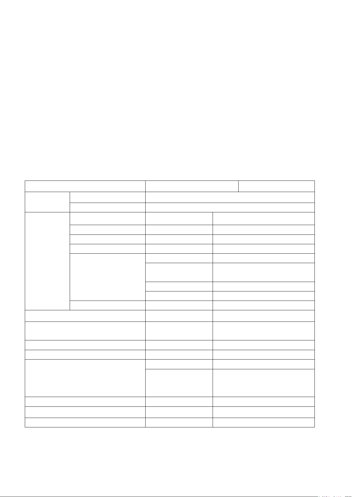
Item
Standard
TV function
sound system
B/G、D/K、I、M
color system
PAL / SECAM / NTSC
Audio and video
signal input
AV
AV x 1
Audio L/R x 2
aberration signal
YPbPr x 1
support to1080P ,Audio L/R x 1,
HDMI
HDMI x3
support to1080P
USB
USB x1
support media player
PC input
plug and use
input frequency
H: 31.5K -50KHz
V: 60Hz
recommend
1280x768(60HZ)
Phone x 1
PC audio input
SCART
SCART x 1
CVBS、RGB、AUDIO
Video output
Output CVBS signal
Output TV ,Audio L/R x 1
Audio output
Audio output L / R
8W inner speakers for each channel
Support Dolby Pro Logic
SPDIF
Optical Fiber
Support Audio output
Power
power supply
AC100V~240V, 50/60Hz
requirement for environment
power achievement
<150W
operation temperature
storage temperature
operation humidity
+ 0° ~ + 40° ,
- 20 ° ~ + 60°
10% ~ 85%
appearance size
W x H x D
net weight
no accessory
Kg
dismantle, we can take some photos of the line route for the comparison of installing.
(4)After check and maintenance, please assure that there is no foreign body in the machine when install.
1-5 High-voltage warning
The high-voltage of the LED screen is generated by the power supply board, without attention to exposure to
the high voltage, one may meet a serious electricity shock.
Chapter2 whole machine standard and terminal functions
2-1 Basic standard
Page 5
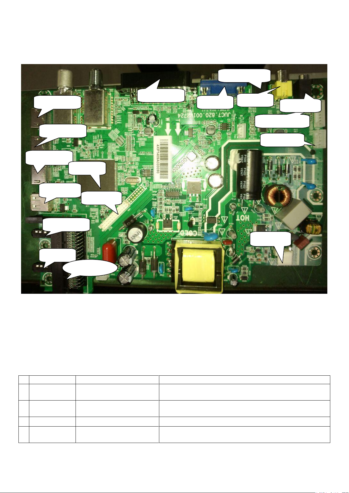
2-2 Introduction of terminals(practicality photos)
No.
Item no.
Model
Main function
1
A001
DMI21-C8I2RH(JUB2.891.367-1)
Tuner output IF signal
Support PAL\NTSC\SECAM\DVB-T\DVB-C
2
AS001
EDS-11670FNPRB
Tuner output IF signal
Support DVB-S/DVB-S2
3
U201
9206B
Video decoder, image processor, A/D and D/A conversion
4
U700
R-RT9108NBGCP
15W Stereo (BTL) Analog Input Audio Amplifier with
Power Limiter and DC Detect
SPDIF
HDMI1 input
PC input
YpbPr1 input
PC audio input
AV1 input
HDMI2 input
Keypad IR input
Audio output
Lvds output
Power input
HDMI3 input
USB1 input
Main Chip
Headphone
SCART/AVO
CI1
ATTENTION:
1.HDMI and YPbPr support to 1080P;
2.The recommendation resolving ratio of PC is 1280X768;
Chapter3 Main chip functions and the introductions of power supply
3-1 Main IC and functions of HLT57EJ
Page 6

5
U207
GD25Q64BSIG
64 Mbit(8M x8bit), low voltage, Serial Flash memory
6
U802
MP1471
12V to 1.0V DC-DC/For COER
7
U801
TPS54428E
12V_standby to 5VS VDC-DC
8
U803
AMS1117-ADJ
5V to 1.5V LDO/For DDR3 & Main Chip
9
U805
AMS1117-3.3V
5V to 3.3V LDO/NORMAL
10
U804
AMS1117-3.3V
5V to 3.3V LDO/Standby
12
U806
AMS1117-ADJ
5V to 3.3V LDO/TUNER
U207:Flash Memory
U803: LDO-1.5V
A001:
DMI21-C8I2RH(JUB2.891.36
U700:
RT9108NBGCPRT9108N
U201: 9206B
U805: LDO-3.3V
U806: LDO-3.3V
U804: LDO-3.3V
U802:DC-DC
U801:DC-DC
.
3-2 Pin function description of HTL57EJ chip
3-2-1 9206B recommended operating power conditons
(The Main Chip cancel 1.8V Supply Voltages because of DDR3 supplied by 1.5V )
Page 7
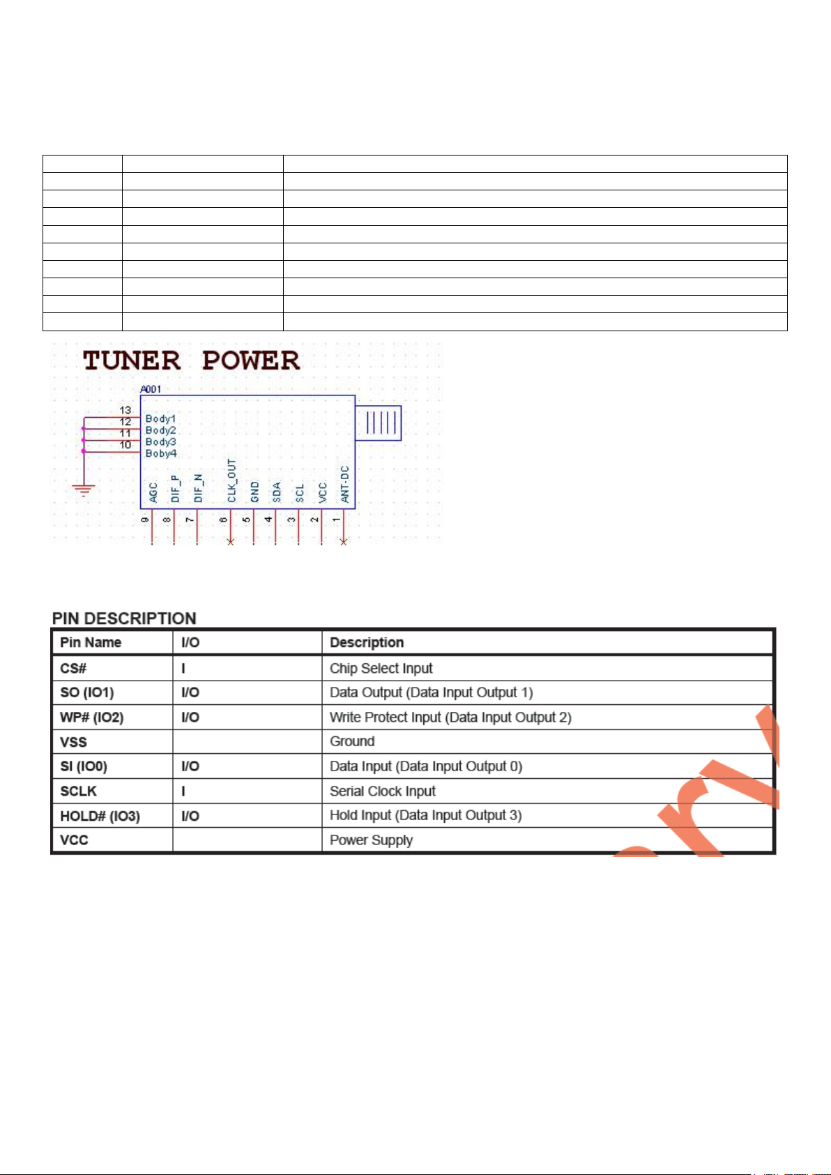
PIN
SYMBOL
Description
1
Ant power
Not connect
2
VCC
+3.3V POWER
3
SCL
I2C Serial Clock
4
SDA
I2C Serial DATA
5
GND
Ground
6
CLK_OUT
Not connect
7
DIF_N
High level IF output2
8
DIF_P
High level IF output1
9
IF-AGC
IF AGC Control Voltage
3-2-2 Pin function of DMI21-C8I2RH(JUB2.891.367-1) tuner
3-2-3 GD25Q64BSIG 64Mbit(8M x 8bit) brief introduction:
4-1 9206B Power Block Diagram
Page 8
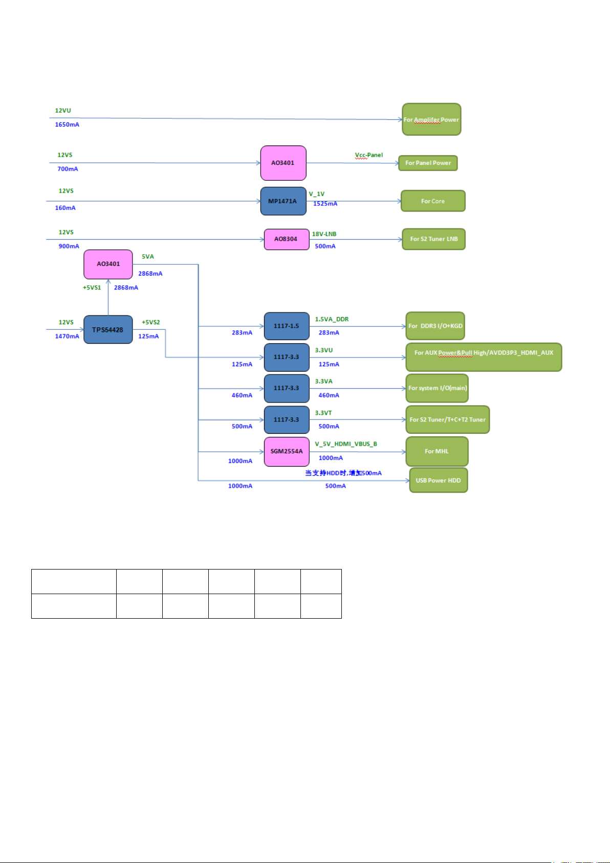
item No.
U802
U805
U806
U804
U803
output voltage
1.0V
1.5V
3.3V
3.3V
3.3
4-2 Power supply system
4-2-1 Pin voltage of the voltage adjustor on the mainboard
Page 9

3.3V
1.5V
1.0V
3.3V
3.3
Page 10
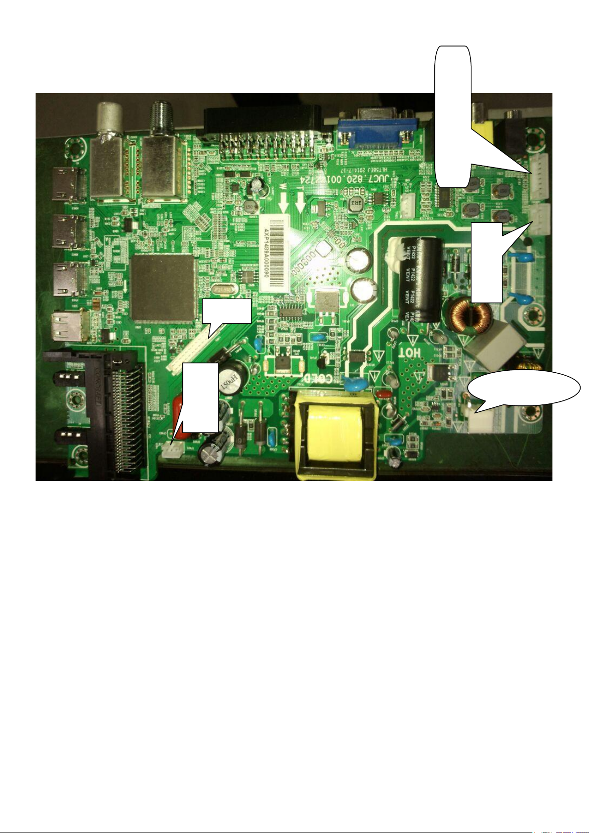
4-2-3 Interface definition
GND
KEY0
KEY1
LEDG
LEDR
IR-IN
GND
5VS
L+
LRR+
LED+
NC
LED_
LVDS
Power input
Page 11
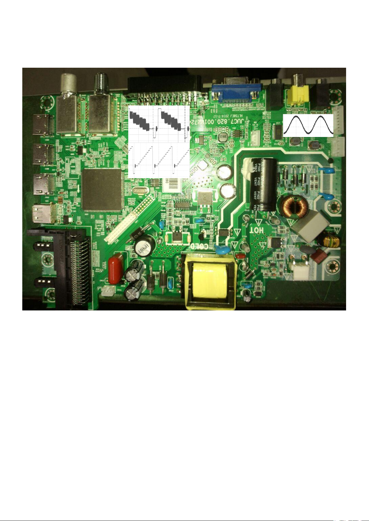
4-3 The waveform of key points
5-1 UART Upgrade
Page 12

Chapter5 Software upgrade instructions
c) 4-Pin Reverse Wire
Page 13

Page 14

Page 15

Page 16

Page 17

5.2 USB Upgrade
Page 18

Chapter6: Classical accident maintenance procedures and examples
6-1 The thinking of don’t boot
The power is not connected.
Page 19

6-2 Common problems for your reference
Symptoms
Possible Reason
Solutions
No picture, no sound, and no
indicator light on
1.The power cord is not plugged in
2.The power is off
1.Plug in the power cord
2.Turn the power on
abnormity Picture and sound with
1.Contrast, sharpness, and color are set
improperly
2.Color system is improperly
3.Sound system is improperly
1.Adjust the numberical value of
Contrast, sharpness, and color
2.Set the Color system to the country
broadcasting standard
3.Set the Sound system to meet the
country’s broadcasting standard
Picture is spotted or with snow
Signal source is low-grade or the signal
cord is in a lower quality
Use the qualified signal cord
No picture, no sound and indicator
light is green
Contrast, brightness, color and volume are
all in the minimum value or TV is in mute
mode.
Adjust the value of contrast,
brightness, color and volume
The signal cable is not correctly connected.
Connect the signal cable correctly
Blue screen, AV or SVIDEO is
displayed
There is no signal input or the video cable is
not connected or incorrectly connected
Connect the video cable correctly
No sound
There is no audio signal input or audio
cable is not connected correctly
Connect the audio cable correctly
VGA picture display with improper
color
The color temp is adjusted incorrectly by
user
Readjust the color temp, or select
the original color setting
HDMI source, with snow pixel of
full screen
The signal source is not normal
Plug the HDMI cable again
The remote control does not work
Batteries are improperly installed or
exhausted
1. Make sure the positive and the
negative polarities are correct.
2.Check if there is a loose contact
between the batteries and the springs
3.Replace the batteries
Number
Name
Part number
Proportion of easy damage
(‰)
1
Mainboard part
JUC6.690.00117679
2
2
Remote receiving
board part
JUC6.695.00113324
0.5 3 Keyboard part
JUC6.694.00114533
0.5 4 Inner power module
To speed you to dignose and solve problems, the following commom problems are offered for your
reference.
Chapter7 High voltage and high current wearing parts list
The introduction of maintenance parts are for reference only, modification of parameters will not be
informed any more. For accurate data and related specifications, please consult the newest data of our
company.
Page 20

Three in one
5 5 LED screen
C320X14-E1-H(G3)
0.1 6 Dynamic speaker
YDT35135-A3-10W-8Ω
2
Menu level
paramete
r values
secondary menu
parameter
values
function declaration
Version
select version
System Config
Board Defined
Changhong_S
2T512
Default Language
English
The default language
setting
Default Country
Germany
Set the default state
OSD Language
OSD language settings
DVD Android Option
DVD Android related
settings
6m20 6m30 Option
6m20 6m30 related
settings
Pre Channel Setting
Advanced Setup
Power Show Logo
Show Logo
LOGO display switch
AC Auto Power ON
LASTMemory
Selected by switch
Input Source
channel switch
Physical Input
Setting
Channel Settings
Use CI+ 1.2 Stack
Only
False
Picture Mode
ADC Adjust
ADC autocorrection
W/B Adjust
Exposure Pro
Chapter8 Factory mode parameter setting instructions and notes
8-1 Enter into the factory mode
Switch on TV set, and make it works normally:
Press 【SOURCE】 key on the remote control
Press number keys “3”、“1”、“3”、“8” on remote control to enter password. Finish entering the factory mode.
If you want to quit the factory mode, Please. press【EXIT】key to exit source.
⑴Factory menu displays as bellow:
Factory Setting
Page 21

Picture
Image pattern
parameters Settings
Over Scan
A scan Settings
Curve Setting
The linear parameter
Settings
Gamma Switch
Enable
Gamma switch
Select PQ
None
PQ select
Dynamic Contrast
Dynamic contrast
parameter Settings
Color LUT
LUT colour modulation
setting in advance
VIP
HDIM Levels set
Backlight Mode
Home Mode
Backlight Mode
Backlight
60
Backlit parameters
Dynamic Backlight
OFF
Dynamic backlight
switch
CVD2 Setting
Brightness
0
Contrast
0
LDLY
0
Filter
0
Audio
Power Limiter
Power limit set
Audio Effect
Sound Setting
SRS Surround
SRS parameter setting
AVL
AVL parameter setting
Sound Mode
SOUND MODE
Volume
Sound linear mode
EQ Setting
Equalizer Settings
PEQ1
Equilibrium parameter
Settings 1
PEQ2
Equilibrium parameter
Settings 1
PEQ3
Equilibrium parameter
Settings 1
Misc
Audio and video
Settings
Burning Mode
Off
Aging model boot,
According to the remote
control0029or this TV
POWER key exit
Shipping Mode
Reset
Reset all
Reset to reset the
Function
Panel Setting
Screen parameter
Page 22

Settings
SSC Adjust
Spectrum extension set
Preset Channel
preset channel
Full TS Record
Stopped
Frequency point shows
all burn
Video Pattern
Off
Monochrome image mode
selection
Delete Same
Services
Off
Delete the same program
Update
USB Update
software upgrading
HDCP Update
HDCP_KEY data upgrade
CI Plus Key Import
CI Plus Key read-in
6m20 Update
UART DEBUG
On
serial port switch
Factory Remote
Off
Remote control switch
factory
Import/Export Data
import and export
User Settings、
Satellite program
information
Notes:
Set Reset all will clear the memory data, So do not set it unless it is needed; other setting items do not
need setting.
8-2 Setting method of factory menu
⑴ Choose setting item
Operators can choose setting item orderly with【】and【】key, font having background display represents
the item has been chosen. Press【】key to enter sub directory. Use 【】and【】keys on remote control
to make up or down option, and use【】and【】keys to set.
(2)All the menu functions are opened in factory mode, item checking and effect testing can be done by using
menu if it is needed.
(3)Switching TV signal in factory mode can be done by directly pressing the number key. Press【MENU】
key to back to the parent of working directory, press【EXIT】key to quit factory mode.
Page 23

5
4
3
2
1
Power controler
PowerON
BL_ADJ
PB-ADJUST
D D
STANDBY
LOW:OFF
HIGH:ON
1V_EN
MMBT3904
Q805
PowerON 3
BL_ADJ 3,8,13
PB-ADJUST 3,8,13
5VS
R8102.2K
R821 10K
PowerON
standby:HIGH
C848
1uF/10V
STANDBY
R805 4.7K
Q804
R820
C809
1uF/10V
22K
Q803
MMBT3904
DS
AO3415AL
G
R81347K
PB-ADJUST: Default PWM mode
PB-ADJUST
Power for panel
C C
PANEL_ON
B B
BL_ADJ
standby:LOW
R809 4.7K
R80810K
PANEL_ON
Q801 AO3401A
C804
R815
1uF/25V
47K
PANEL_ON 3
R801
47K
Q802
MMBT3904
DC-DC(12VS-5VS)
Vcc-Panel12VS
12VS
L803 0R
Close to DC-DC
C801
10uF/16V
5VA5VS
C807
10uF/16V
DC-DC(12VS-1V_COER)Power Switch
12VS
L804 0R
Close to DC-DC
R812 100K
C827
0.1uF/16V
C834
10uF/16V
C815
NC/1uF/25V
C806
10uF/16V
C823
1uF/25V
C838
0.1uF/16V
C814
3.3nF/50V
1V_EN
R803 100K
U801
TPS54428DDAR
Vin8SW
1
EN
3
VREG5
4
SS
U802
MP1471AGJ
3
5
C835
NC/1uF/25V
VBST
VFB
GND
PWGND
6
VIN
EN
1
6
7
2
5
9
C830 1uF/25V
2
BST
SW
4
FB
GND
L801
C819
0.1uF/16V
1 2
Rb
10uH/3A
L802
R806 150K
注意:5V电压控制在
WSN6045C-3R3N-R
C817
10pF/10V
Ra
R818
12K/1%
+1.03V 1V +/3%
WSN6045C-100M-R
C831
Ra
R80720K/1%
22uF/6.3V
R81627K/1%
Vout=0.8*(1+Ra/Rb)
=1.02V
R804150K/1%
Rb
Close to DC-DC
R819
C822
C820
22uF/6.3V
47K_1%
R811
22K/1%
Vout=0.765*(1+Ra/Rb)
=0.765*(1+126.8/22)
=5.164V
22uF/6.3V
C811
C832
22uF/6.3V
22uF/6.3V
Close to DC-DC
Imax=2460mA
5.2-5.3V
C825
22uF/6.3V
Imax=1560mA
C826
NC/22uF/6.3V
5VS
C837
NC/22uF/6.3V
C803
0.1uF/16V
V_1V
C818
0.1uF/16V
1.5V Normal Power for DDR3
4
U803
AZ1117H-ADJTRE1
ADJ
OUT
R802
Ra
5VA
470R/1%
R814120R/1%
Rb
A A
IN
3
2
1
C828
C810
10uF/16V
0.1uF/16V
Vout=1.25*(1+Rb/Ra)
5
Imax=290mA
V_1.5V
C808
C821
10uF/16V
10uF/16V
5VS
4
4
U804
LR1117/A-3.3$AZ1117H-3.3TR
ADJ
OUT
IN
3
2
1
C812
2.2uF/10V
C824
0.1uF/16V
Imax=130mA
V_3.3V_AUX
C836
10uF/16V
3.3V Normal Power
加大印制板的散
4
ADJ
OUT
2
1
5VA
3
热面积
U805
LR1117/A-3.3$AZ1117H-3.3TR
IN
3
C833
C829
0.1uF/16V
2.2uF/10V
!
Imax=500mA
V_3.3V
C813
10uF/16V
2
3.3V Tuner3.3V Standby Power
4
U806
LR1117/A-3.3$AZ1117H-3.3TR
ADJ
OUT
IN
3
2
5VA
CHANGHONG
Title
Title
Title
System Power
System Power
System Power
Size Document Number Rev
Size Document Number Rev
Size Document Number Rev
Custom
Custom
Custom
S2T512_APCKTVA
S2T512_APCKTVA
S2T512_APCKTVA
Date: Sheet of
Date: Sheet of
Date: Sheet
1
C816
2.2uF/10V
Imax=500mA
V_3.3VT
C805
0.1uF/16V
1
C802
10uF/16V
113Friday, July 18, 2014
113Friday, July 18, 2014
113Friday, July 18, 2014
of
0.1
0.1
0.1
Page 24

5
4
3
2
1
ADC POWER/GND (1.0V/3.3V)
D D
C C
V_1V
V_3.3V
AVDD3P3_HSADC
GND_HSADC
C221
10uF/6.3V
Pin79
C211
10uF/6.3V
AVDD1P0_HSADC
Pin89
C215
0.1uF/16V
GND_HSADC
AVDD3P3_BGP
Pin78
C246
0.1uF/16V
GND_BGP
HDMI POWER/GND (1.0V/3.3V)
V_3.3V_AUX AVDD3P3_HDMI_AUX_T
L211 0R/FB
R-INDC1005L-CH
GND_HDMI_AUX
C240
1uF/10V
Pin150
C241
0.1uF/16V
V_3.3V V_1V
AVDD3P3_HDMI
L201
R-INDC1005L-CH
Pin128
0R/FB
C238
1uF/10V
GND_HDMI_AUX
C239
0.1uF/16V
IVDD POWER (1.0V)
FB for CVDD need Rdc<0.015 , Z=120/100MHz Idc>3A
Default part MHC3216S121W
V_IVDD
V_1V
20140520
2013/07/05
C203
10uF/6.3V
C229
0.1uF/16V
C235
NC/0.1uF/16V
C206
0.1uF/16V
C209
0.1uF/16V
C232
0.1uF/16V
C234
1uF/10V
L203 0R/FB
R-INDC1005L-CH
Pin170/171Pin161/162/163/164 Pin247Pin119Pin56Pin32/34 Pin77 Pin98
C231
0.1uF/16V
AVDD1P0_HDMI
Pin145
50mA
C236
1uF/10V
GND_HDMI
Pin177
C233
0.1uF/16V
C237
0.1uF/16V
C208
0.1uF/16V
PLL POWER/GND (3.3V)
AVDD3P3_MCPLL
GND_PLL
Pin242
C216
0.1uF/16V
V_3.3V
L202
C230
0.1uF/16V
0R/120ohm/100MHZ
R-INDC1005L-CH
Pin243
C247
10uF/6.3V
C243
0.1uF/16V
DEMOD POWER/GND
AUDIO POWER/GND (3.3V)
V_3.3V
靠近IC脚放置
B B
AVDD3P3_AU
!
GND_AU
Pin65
C204
1uF/10V
AVDD3P3HP_AU
Pin71
C214
1uF/10V
GND_AU
3.3V
C225
NC/10uF/6.3V
PIN37放置!
V_3.3V_AUX
Pin37
C219
0.1uF/16V
V_3.3V
Pin32/34
C248
0.1uF/16V
C202
0.1uF/16V
C218
0.1uF/16V
C227
0.1uF/16V
Pin225Pin178 Pin208Pin118
C205
0.1uF/16V
20140521
靠近
DDR POWER (1.5V)
V_1.5V
283mA
VDD1P5
C244
10uF/6.3V
Pin167/168/169
C271
1uF/10V
Pin245/246
C213
0.1uF/16V
LVDS POWER/GND
(3.3V)
V_3.3V
靠近IC脚放置
ALL FB except ADC, CVDD : need Rdc<0.2 , Z=300/100MHz , Idc>500mA
Default part : MCB2012S301H
AVDD3P3_LVDS
Pin256
100mA
C245
!
0.1uF/16V
Pin249
C242
0.1uF/16V
C210
0.1uF/16V
USB POWER/GND
(3.3V)
V_3.3V
AVDD3P3_USB
Pin176
C228
0.1uF/16V
(3.3V/1.0V)
V_3.3V
L204
Demodulatot
以隔离其他电源!
V_1V
L210
DTV IFADC
以隔离其他电源!
0R/120ohm/100MHZ
R-INDC1608N-CH
供电,需预留磁珠
0R/120ohm/100MHZ
R-INDC1608N-CH
供电,需预留磁珠
AVDD3P3_DM
C207
10uF/6.3V
AVDD1P0_DM
C201
10uF/6.3V
Pin108
C212
0.1uF/16V
Pin103
C220
0.1uF/16V
ATV POWER/GND (3.3V)
A A
V_3.3V
5
AVDD3P3_ATV
Pin100
C217
0.1uF/16V
GND_ATV
GND_USB
GND_LVDS
GND_DEMODGNDM
GND_AUX GND_AU
GND_HSADC GND_BGPGND_ATV
*Short these ground planes on PCB
4
3
GND_PLL
GND_HDMIGND_HDMI_AUX
Title
Title
Title
Size Document Number Rev
Size Document Number Rev
Size Document Number Rev
Date: Sheet
Date: Sheet
2
Date: Sheet
GND_AMP
CHANGHONG
S2T512_256QFP_Power
S2T512_256QFP_Power
S2T512_256QFP_Power
B
B
B
S2T512_APCKTVA 0.1
S2T512_APCKTVA 0.1
S2T512_APCKTVA 0.1
213Thursday, June 19, 2014
213Thursday, June 19, 2014
213Thursday, June 19, 2014
1
of
of
of
Page 25

5
V_3.3V_AUX
C266
1uF/10V
<Voltage range>
GND GND
D D
Crystal Circuit
C254
33pF/50V
These components close to IC
HW Trap
R212 10K
GND
HDMI_ARC default A
C C
HDMI_MHL default B
HDMI_CEC
HDMI_A
HDMI_B
HDMI_C
B B
VGA & UART
HDTV Input
1:Scart
2:YPbPr
CVBS Input
0:Scart
1:AV
A A
CVBS output for Scart
Scart function
Audio Input
0:Scart
1:VGA(PC)
2:YPbPr/AV
2013/07/03
Y201
24.576MHz-2P
12
3
CL=15~20pF
GND
SDA_HDMI_A4
SDA_HDMI_B4
SDA_HDMI_C4
RXD0/VGA_SCL5
TXD0/VGA_SDA5
HDMI_ARC4
ENVBUS4
HPD_HDMI_A4
SCL_HDMI_A4
HPD_HDMI_B4
SCL_HDMI_B4
HPD_HDMI_C4
SCL_HDMI_C4
HS_VGA5
VS_VGA5
B_IN5
G_IN5
R_IN5
R217 1K
R20110K
C1=C2=2*CL-5
ARC_DET4
CD_SENSE4
CEC_HDMI4
RXCM_A4
RXCP_A4
RXM0_A4
RXP0_A4
RXM1_A4
RXP1_A4
RXM2_A4
RXP2_A4
RXCM_B4
RXCP_B4
RXM0_B4
RXP0_B4
RXM1_B4
RXP1_B4
RXM2_B4
RXP2_B4
RXP2_C4
RXM2_C4
RXP1_C4
RXM1_C4
RXP0_C4
RXM0_C4
RXCP_C4
RXCM_C4
Y1_IN6
SOY1_IN6
PB1_IN6
PR1_IN6
Y2_IN5
SOY2_IN5
PB2_IN5
PR2_IN5
CVBS0_IN6
CVBS1_IN6
CVBSO6
SCART_FS6
SCART_FB6
AIN0L6
AIN0R6
AIN1L5
AIN1R5
AIN2L6
AIN2R6
AUXOK
AUX_PWROK
XTALI
XTALO
20140519
删掉
XOSCO24_R
C256
33pF/50V
SCK_FLASH
HPD_HDMI_C
SDA_HDMI_C
SCL_HDMI_C
RXCP_C
RXCM_C
R202
HDMI_ARC
ARC_DET
CD_SENSE
ENVBUS
CEC_HDMI
HPD_HDMI_A
SDA_HDMI_A
SCL_HDMI_A
RXCM_A
RXCP_A
RXM0_A
RXP0_A
RXM1_A
RXP1_A
RXM2_A
RXP2_A
HPD_HDMI_B
SDA_HDMI_B
SCL_HDMI_B
RXCM_B
RXCP_B
RXM0_B
RXP0_B
RXM1_B
RXP1_B
RXM2_B
RXP2_B
RXP2_C
RXM2_C
RXP1_C
RXM1_C
RXP0_C
RXM0_C
HS_VGA
VS_VGA
B_IN
G_IN
R_IN
RXD0/VGA_SCL
TXD0/VGA_SDA
Y1_IN
SOY1_IN
PB1_IN
PR1_IN
Y2_IN
SOY2_IN
PB2_IN
PR2_IN
CVBS0_IN
CVBS1_IN
CVBSO
SCART_FS
SCART_FB
AIN0L
AIN0R
AIN1L
AIN1R
AIN2L
AIN2R
5
V_3.3V
GNDM
V_IVDD
V_3.3V_AUX
BL_ADJ
Close to IC
For ESD
L212 CBW1608U221T/10R
SPI Flash
KEYPAD Input
USB Input
RMII & TUNER Reset
C261
1uF/10V
AIN2L
AIN2R
AIN1L
AIN1R
AIN0L
AIN0R
SD1_FLASH7
SD0_FLASH7
CEN_FLASH7
SCK_FLASH7
KEYPAD07
KEYPAD17
USB0_DM4
USB0_DP4
RMII/TUNER_RESET_N11
20140520
20140520
V_IVDD
C250 1uF/10V
C268 1uF/10V
C265 1uF/10V
C252 1uF/10V
C255 1uF/10V
LVA_CKP
LVA_CKN
LVA_TXP3
LVA_TXN3
LVA_TXP4
LVA_TXN4
LVB_TXP0
LVB_TXN0
LVB_TXP1
LVB_TXN1
LVB_TXP2
LVB_TXN2
LVB_CKP
LVB_CKN
LVB_TXP3
LVB_TXN3
LVB_TXP4
LVB_TXN4
SCART_FS
SCART_FB
RMII/TUNER_RESET_N
KEYPAD0
KEYPAD1
XTALI
XTALO
PowerON
IR_DAT
SD0_FLASH
SCK_FLASH
SD1_FLASH
CEN_FLASH
LED_G_ON
ARC_DET
STB_LED_R
MUTE_AMP
SPDIF_OUT
AUX_PWROK
PANEL_ON
C262 4.7uF/6.3V
R209 33K
R204 33K
R220 33KC259 1uF/10V
R214 33K
R208 33K
R211 33K
SD1_FLASH
SD0_FLASH
CEN_FLASH
SCK_FLASH
KEYPAD0
KEYPAD1
USB0_DM
USB0_DP
RMII/TUNER_RESET_N
VBG_AU
AVSS3P3_AU
GPIO5
4
U201
1
LVA_CKP
2
LVA_CKN
3
LVA_TXP3
4
LVA_TXN3
5
LVA_TXP4
6
LVA_TXN4
7
LVB_TXP0
8
LVB_TXN0
9
LVB_TXP1
10
LVB_TXN1
11
LVB_TXP2
12
LVB_TXN2
13
LVB_CKP
14
LVB_CKN
15
LVB_TXP3
16
LVB_TXN3
17
LVB_TXP4
18
LVB_TXN4
19
KEY2
20
KEY3
21
RMIIMDIO/SW0
22
RMIIMDC
23
RMII50MCK
24
RMIIRXER/I2S_SCK
25
RMIIRXD0/DVD_AUTO
26
RMIIRXD1
27
RMIIRXDV/SPDIF_IN
28
RMIITXEN/DVD ONOFF
29
RMIITXD0/DVD_IR
30
RMIITXD1/DVD_STB
31
OVDD3P3-1
32
IVDD1P0-1
33
VSS1P5_DDR
34
IVDD1P0
35
KEY0
36
KEY1
37
OVDD3P3_AUX
38
OSCI
39
OSCO
40
PWRSW
41
BL_ON
42
BL_ADJ
43
IR
44
SPI_DO
45
SPI_CKO/ENTEST
46
SPI_DI
47
SPI_CSN0
48
AUX_I2CM_SDA1
49
AUX_I2CM_SCL1
50
LRSYNC/SPDIF_IN
51
SPK_MUTE
52
PWM0
53
SPDIFO/ENDEBUG
54
AUXOK
55
LCD_EN
56
IVDD1P0-2
57
VBG_AU
58
AVSS3P3_AU
59
LINEIN_L3
60
LINEIN_R3
61
LINEIN_L2
62
LINEIN_R2
63
LINEIN_L1
64
LINEIN_R1
S2T512_256QFP
7
6
1
NC
4
257
GND
8
1
2
3
H5
4
5
D4
Hole & Mark
1
M1
NC
AVDD3P3_LVDS
LVA_TXP2
LVA_TXP1
LVA_TXN2
LVA_TXN1
256
254
252
255
253
LVA_TXP2
LVA_TXN2
LVA_TXN1
AVDD3P3_LVDS
LINEOUT_L
AVDD3P3_AU
67
66
65
AUO_1L
AUO_0L
AUO_1R
AUO_0R
AVDD3P3_AU
1
M2
GNDM
LVA_TXP0
LVA_TXN0
249
250
251
LVA_TXP1
LVA_TXP0
LVA_TXN0
SPK_R69SPK_L68LINEOUT_R
AVDD3P3HP_AU
HP_L
72
71
70
HP_L
HP_R
AVDD3P3HP_AU
7
6
M3
NC
V_IVDD
VDD1P5
R223 240R/1%
R221 120R/1%
20140519
DDR_ZQ
243
247
245
246
248
244
DDR_ZQ
NC_TEST
IVDD1P0-15
VDD1P5_DDR-2
VDDQ1P5_DDR-3
VDDQ1P5_DDR-4
UARTA_TX/VGA_SDA
UARTA_RX/VGA_SCL
VGA_HS75VGA_VS
IVDD1P0-4
HP_R
73
74
76
78
77
HS_VGA
RXD0/VGA_SCL
TXD0/VGA_SDA
VS_VGA
V_IVDD
C272 NC/15pF/50V
20140522
8
1
2
3
H3
4
5
D5
1
M4
NC
AVDD3P3_MCPLL
AVDD3P3_MCPLL
AVDD3P3_BGP
AVDD3P3_BGP
R21510K
V_IVDD
EFUSE
241
240
242
IVDD1P0-14
EFUSE_GND
NF_DQS/I2S_MCK
239
238
NF_IO7
237
NF_IO6
236
NF_IO5
235
NF_IO4
234
NF_IO3
NF_IO2
233
232
NF_IO1
231
NF_IO0
NF_WPN
TSO_SYNC
230
TS_FRAME
S2T512
YPP_SOG184YPP_G185YPP1_REF86YPP_B187YPP_R1
AVDD3P3_HSADC
VGA_B080VGA_G081VGA_REF82VGA_R083AVDD1P0_HSADC
79
VGA_RREF
B_IN
G_IN
R_IN
AVDD3P3_HSADC
SOY1_IN
Y1_IN
YPBPR1_GREF
8
7
6
5
8
7
6
5
88
89
PB1_IN
PR1_IN
AVDD1P0_HSADC
4
4
YPP_SOG2
91
SOY2_IN
YPBPR2_GREF
1
2
3
H7
D4
1
2
3
H9
D4
TSO_CLK
TSO_VAL
CI_D2
229
228
227
TS_CLK
TS_VALID
YPP_G292YPP2_REF90YPP_B293YPP_R2
94
PB2_IN
PR2_IN
Y2_IN
V_3.3V
CI_D1
225
226
CI_DAT2
CI_DAT1
OVDD3P3-5
AV_Y196AV_Y295AV_REF97IVDD1P0-5
CVBS0_IN
CVBS1_IN
CI_D0
CI_A0
224
223
CI_ADD0
98
AV_REF
7
6
7
6
3
CI_A2
CI_A1
CI_A3
222
221
220
CI_DAT0
CI_ADD1
CI_ADD2
AVDD3P3_ATV
ATV_CVBSO99DMVINP_I
100
101
IF_IP
22pF/50V
CVBSO
C269
V_IVDD
AVDD3P3_ATV
8
4
5
8
4
5
3
CI_A4/TSO_D7
CI_A5/TSO_D6
CI_A6/TSO_D5
CI_WAIT
CI_RST
219
216
215
217
218
CI_ADD3
CI_RESET
CI_WAIT_N
CI_ADD4/TS_DAT7
CI_ADD5/TS_DAT6
DMVINN_I
DMVINP_Q
DMVINN_Q
AVDD1P0_DM
106
102
105
104
103
IF_QP
IF_QN
IF_IN
22pF/50V
22pF/50V
22pF/50V
C249 0.1uF/16V
C270
C263
C251
LIFN
AVDD1P0_DM
1
2
3
H6
D5
1
2
3
H8
D5
V_3.3V
TSI_D4
TSI_D5
TSI_D3
CI_A7/TSO_D4
CI_A8/TSO_D3
CI_WE
CI_A9/TSO_D2
CI_IRQ
CI_IOWR
CI_D6
CI_CE
CI_A10/TSO_D1
CI_A11/TSO_D0
CI_OE
CI_IORD
214
211
210
212
207
209
208
205
213
CI_ADD6/TS_DAT5
CI_ADD7/TS_DAT4
DMVINP
DMVINN
108
107
C260 0.1uF/16V
LIFP
AVDD3P3_DM
204
202
203
206
CI_OE_N
CI_WE_N
CI_IRQ_N
AVDD3P3_DM
AVSS3P3_DM
110
109
VBG_DM
AVSS3P3_DM
C264 4.7uF/6.3V
109脚为Demodulator的3.3V
磁珠与其他地隔离,以确保
L213 CBW1608U221T/10R
CI_CE1_N
CI_IORD_N
CI_IOWR_N
OVDD3P3-4
CI_ADD8/TS_DAT3
CI_ADD9/TS_DAT2
CI_ADD10/TS_DAT1
CI_ADD11/TS_DAT0
I2CM_SCL
I2CM_SDA
IFGAIN
T2_FEF/I2S_SD0
RFGAIN/I2S_WS
DISEQ_I/HP_DET
DISEQ_O
OVDD3P3-2
VBG_DM
115
114
113
119
111
112
116
117
118
TP201
SCL_M
SDA_M
HP_DET
D_IFAGC
DISEQC_OUT
D-RFAGC
TP203
V_3.3V
V_IVDD
YPBPR1_GREF VGA_RREF
CIIN_CD1
CI_D4
CI_D7
CI_D5
198
201
200
199
CI_DAT6
CI_DAT7
CI_DAT5
CI_DAT4
HDMIA_RXCN
HDMIA_RXCP
HDMIA_RX0N
IVDD1P0-6
120
121
122
123
RXCP_A
RXCM_A
RXM0_A
RXP0_A
供电接地,需加上
DTV
C257 47nF/16V
C258 47nF/16V
CI_D3
196
195
194
197
CI_DAT3
CI_CD1_N
CATS_DAT3
CATS_DAT4
AVDD3P3_HDMI_AUX_T
HDMIA_RX0P
HDMIA_RX1N
HDMIA_RX1P
HDMIA_RX2N
124
125
126
127
RXP2_A
RXM2_A
RXM1_A
RXP1_A
质量!
50V
50V
TSI_D6
193
CATS_DAT6
CATS_DAT5
CATS_DAT7
CATS_CLK
CATS_VALID
CATS_FRAME
CATS_DAT0
CATS_DAT1
CATS_DAT2
NF_RBN
NF_REN
NF_WEN
NF_ALE
NF_CLE
NF_CEN1
NF_CEN0
OVDD3P3-3
IVDD1P0-13
AVDD3P3_USB
USB_DP1
USB_DM1
USB_DP0
USB_DM0
IVDD1P0-12
IVDD1P0-11
VDDQ1P5_DDR-2
VDDQ1P5_DDR-1
VDD1P5_DDR-1
NC_TEST-2
NC_TEST-1
IVDD1P0-10
IVDD1P0-9
IVDD1P0-8
IVDD1P0-7
IVDD_SEL
HDMI_ARC
HDMI_CEC
CD_SENSE
HDMIA_SCL
HDMIA_SDA/5V_DCT
HDMIB_SCL
HDMIB_SDA/5V_DCT
HDMIC_SCL
HDMIC_SDA/5V_DCT
HDMIA_HPD/CBUSA
HDMIB_HPD/CBUSB
HDMIC_HPD
VBUS_EN
AVDD1P0_HDMI
HDMIC_RX2P
HDMIC_RX2N
HDMIC_RX1P
HDMIC_RX1N
HDMIC_RX0P
HDMIC_RX0N
HDMIC_RXCP
HDMIC_RXCN
HDMIB_RX2P
HDMIB_RX2N
HDMIB_RX1P
HDMIB_RX1N
HDMIB_RX0P
HDMIB_RX0N
HDMIB_RXCP
HDMIB_RXCN
HDMIA_RX2P
AVDD3P3_HDMI
128
AVDD3P3_HDMI
R210 68R
GND_HSADC GND_HSADC
R207 68R
2
TSI_D7
192
TSI_CLK
191
TSI_VAL
190
TSI_SYNC
189
TSI_D0
188
TSI_D1
187
TSI_D2
186
185
184
183
182
181
180
179
178
177
176
175
174
USB0_DP
173
USB0_DM
172
171
170
169
168
167
166
20140520
165
164
163
162
161
160
HDMI_ARC
159
CEC_HDMI
158
CD_SENSE
157
SCL_HDMI_A
156
SDA_HDMI_A
155
SCL_HDMI_B
154
SDA_HDMI_B
153
SCL_HDMI_C
152
SDA_HDMI_C
151
150
HPD_HDMI_A
149
HPD_HDMI_B
148
HPD_HDMI_C
147
146
ENVBUS
145
144
143
142
141
140
139
138
137
136
135
134
133
132
131
130
129
RXP2_C
RXM2_C
RXP1_C
RXM1_C
RXP0_C
RXM0_C
RXCP_C
RXCM_C
RXP2_B
RXM2_B
RXP1_B
RXM1_B
RXP0_B
RXM0_B
RXCP_B
RXCM_B
*Short these ground planes on PCB
GND_HDMI GNDMGND_LVDSGND_HSADC GND_AU
AV_REFYPBPR2_GREF
These components close to IC
2
V_3.3V
V_IVDD
AVDD3P3_USB
V_IVDD
VDD1P5
V_IVDD
AVDD3P3_HDMI_AUX_T
AVDD1P0_HDMI
C253 47nF/16V
50V
C267 0.22uF/16V
50V
20140519
原
:47nF
R206 68R
R216 180R
1
LVDS Output
LVA_TXP0
LVA_TXN0
LVA_TXP1
LVA_TXN1
LVA_TXP2
LVA_TXN2
LVA_CKP
LVA_CKN
LVA_TXP3
LVA_TXN3
LVA_TXP4
LVA_TXN4
LVB_TXP0
LVB_TXN0
LVB_TXP1
LVB_TXN1
LVB_TXP2
LVB_TXN2
LVB_CKP
LVB_CKN
LVB_TXP3
LVB_TXN3
LVB_TXP4
LVB_TXN4
TX1P4
TX1M4
TX1P3
TX1M3
TXCLK1P
TXCLK1M
TX1P2
TX1M2
TX1P1
TX1M1
TX1P0
TX1M0
TX0P4
TX0M4
TX0P3
TX0M3
TXCLK0P
TXCLK0M
TX0P2
TX0M2
TX0P1
TX0M1
TX0P0
TX0M0
GPIO
PANEL_ON
PowerON
BL_ADJ
LED_G_ON
STB_LED_R
IR_DAT
MUTE_AMP
CI
CI_A0
CI_A1
CI_A2
CI_A3
CI_A4/TSO_D7
CI_A5/TSO_D6
CI_A6/TSO_D5
CI_A7/TSO_D4
CI_A8/TSO_D3
CI_A9/TSO_D2
CI_A10/TSO_D1
CI_A11/TSO_D0
TSO_SYNC
TSO_VAL
TSO_CLK
TSI_D0
TSI_D1
TSI_D2
TSI_D3
TSI_D4
TSI_D5
TSI_D6
TSI_D7
TSI_SYNC
TSI_CLK
TSI_VAL
CI_D0
CI_D1
CI_D2
CI_D3
CI_D4
CI_D5
CI_D6
CI_D7
CI_CE
CI_WE
CI_RST
CI_OE
CI_IORD
CI_IOWR
CI_WAIT
CIIN_CD1
CI_IRQ
T/T2 DEMOD
D_IFAGC
LIFP
LIFN
TX0M0
TX0P0
TX0M1
TX0P1
TX0M2
TX0P2
TXCLK0M
TXCLK0P
TX0M3
TX0P3
TX0M4
TX0P4
TX1M0
TX1P0
TX1M1
TX1P1
TX1M2
TX1P2
TXCLK1M
TXCLK1P
TX1M3
TX1P3
TX1M4
TX1P4
PANEL_ON 1
PowerON 1
BL_ADJ 8,13
LED_G_ON 7
STB_LED_R 7
IR_DAT 7
MUTE_AMP 9
CI_A0 10
CI_A1 10
CI_A2 10
CI_A3 10
CI_A4/TSO_D7 10
CI_A5/TSO_D6 10
CI_A6/TSO_D5 10
CI_A7/TSO_D4 10
CI_A8/TSO_D3 10
CI_A9/TSO_D2 10
CI_A10/TSO_D1 10
CI_A11/TSO_D0 10
TSO_SYNC 10
TSO_VAL 10
TSO_CLK 10
TSI_D0 10
TSI_D1 10
TSI_D2 10
TSI_D3 10
TSI_D4 10
TSI_D5 10
TSI_D6 10
TSI_D7 10
TSI_SYNC 10
TSI_CLK 10
TSI_VAL 10
CI_D0 10
CI_D1 10
CI_D2 10
CI_D3 10
CI_D4 10
CI_D5 10
CI_D6 10
CI_D7 10
CI_CE 10
CI_WE 10
CI_RST 10
CI_OE 10
CI_IORD 10
CI_IOWR 10
CI_WAIT 10
CIIN_CD1 10
CI_IRQ 10
D_IFAGC 12
LIFP 12
LIFN 12
TX0M0 8
TX0P0 8
TX0M1 8
TX0P1 8
TX0M2 8
TX0P2 8
TXCLK0M 8
TXCLK0P 8
TX0M3 8
TX0P3 8
TX0M4 8
TX0P4 8
TX1M0 8
TX1P0 8
TX1M1 8
TX1P1 8
TX1M2 8
TX1P2 8
TXCLK1M 8
TXCLK1P 8
TX1M3 8
TX1P3 8
TX1M4 8
TX1P4 8
S2 DEMOD
DISEQC_OUT
IF_IP
IF_IN
IF_QN
IF_QP
I2C
SCL_M
SDA_M
AUDIO Output
AUO_0L
AUO_0R
AUO_1L
AUO_1R
HP_L
HP_R
HP_DET
SPDIF output
SPDIF_OUT
GND_HSADCGND_HSADC
Title
Title
Title
S2T512_256QFP_MAIN
S2T512_256QFP_MAIN
S2T512_256QFP_MAIN
Size Document Number Rev
Size Document Number Rev
Size Document Number Rev
S2T512_APCKTVA
S2T512_APCKTVA
S2T512_APCKTVA
Custom
Custom
Custom
Date: Sheet
Date: Sheet
Date: Sheet
SCL_M
R213 2K
SDA_M
R222 2K
SCL_RFSCL_M
SDA_RFSDA_M
CHANGHONG
1
DISEQC_OUT 11
IF_IP 11
IF_IN 11
IF_QN 11
IF_QP 11
V_3.3V
SCL_M 8,11,12
SDA_M 8,11,12
SCL_RF 8,11,12
SDA_RF 8,11,12
SPK_L 9
SPK_R 9
LINEOUT_L 6
LINEOUT_R 6
HP_L 9
HP_R 9
HP_DET 9
SPDIF_OUT 7
AMP
Scart
Hearphone
of
313Thursday, June 19, 2014
of
313Thursday, June 19, 2014
of
313Thursday, June 19, 2014
0.1
0.1
0.1
Page 26

5
4
3
2
1
HDMI PORT-A HDMI PORT-B(MHL)
V_5V_HDMI_A
R5133.3K
ARC_DET
R529
4.7K
HPD_HDMI_A
SDA_HDMI_A
SCL_HDMI_A
SCL_HDMI_A
SDA_HDMI_A
D D
HDMI3
21
DATA2+
21
DATA2 SHIELD
DATA2-
DATA1+
DATA1 SHIELD
DAT1A-
DATA0+
DATA0 SHIELD
DATA0-
CLK+
CLK SHIELD
CLK-
22
23
C C
20
22
23
DDC/CEC GND
+5V POWER
HOT PLUG
20
W
CEC
ARC
SCL
SDA
HDMI CEC
V_3.3V_AUX
B B
CEC_A
CEC_C
A A
R51427K
D502
LL4148
5
1
2
3
4
5
6
7
8
9
10
11
12
13
14
15
16
17
18
HPD_HDMI2_A
19
CEC_HDMI
R519 100R
RXP2_A
RXM2_A
RXP1_A
RXM1_A
RXP0_A
RXM0_A
RXCP_A
RXCM_A
CEC_A
ARC
V_5V_HDMI_A
ARC
R524 33R
CEC_HDMI 3
CEC_HDMICEC_B
5VS
R5034.7K
R52247K
R525 100R
R530 100R
R527
NC/1M
HPD_HDMI_A
HDMI ARC
RXP2_A
RXM2_A
RXP1_A
RXM1_A
RXP0_A
RXM0_A
RXCP_A
RXCM_A
20140521
HPD_HDMI_A 3
SDA_HDMI_A 3
SCL_HDMI_A 3
RXP2_A 3
RXM2_A 3
RXP1_A 3
RXM1_A 3
RXP0_A 3
RXM0_A 3
RXCP_A 3
RXCM_A 3
20140519
删掉
HDP脚的1M
C501 1uF/10V
ARC
4
下拉电阻
HDMI_ARC
ARC_DET
R521
82R
HDMI2
21
21
DATA2 SHIELD
DATA1 SHIELD
DATA0 SHIELD
22
22
23
23
DDC/CEC GND
20
20
W
HDMI_ARC 3
ARC_DET 3
R512 180R
DATA2+
DATA2-
DATA1+
DAT1A-
DATA0+
DATA0-
CLK+
CLK SHIELD
+5V POWER
HOT PLUG
HDMI_ARC
1
2
3
4
5
6
7
8
9
10
11
12
CLK-
13
CEC
14
ARC
15
SCL
16
SDA
17
18
HPD_HDMI2_B
19
HDMI MHL
RXP2_B
RXM2_B
RXP1_B
RXM1_B
RXP0-B
RXM0-B
RXCP_B
RXCM_B
CEC_B
MHL_DET
R533
R534 4R7
R501 33R
C502
47nF/16V
ENVBUS
3
4R7
RXP0_B
RXM0_B
V_5V_HDMI_VBUS_B
R509
4.7K
R520
1M
HPD_HDMI_B
MHL
C506
39pF/50V
Close IC
R515 100R
下拉电阻必须为
R518300K
5VS
R504 1K
HPD_HDMI_B
SDA_HDMI_B
SCL_HDMI_B
RXP2_B
RXM2_B
RXP1_B
5VS
RXM1_B
RXP0_B
RXM0_B
RXCP_B
RXCM_B
R528
47K
R523 100R
R511 100R
300K
CD_SENSEMHL_DET
SCL_HDMI_B
SDA_HDMI_B
20140519
删掉
R532
10K
HPD_HDMI_B 3
SDA_HDMI_B 3
SCL_HDMI_B 3
RXP2_B 3
RXM2_B 3
RXP1_B 3
RXM1_B 3
RXP0_B 3
RXM0_B 3
RXCP_B 3
RXCM_B 3
RXP0-B
RXM0-B
D505
D504NC
NC
HDP脚的1M
ENVBUS
CD_SENSE
U501
SGM2554A
3
OUT1
IN
4
OUT
EN
GND
2
下拉电阻
HDMI PORT-C
HDMI1
21
21
22
22
23
23
20
20
W
ENVBUS 3
CD_SENSE 3
trace width >10mil
V_5V_HDMI_VBUS_B
1000mA
1
5
C505
2.2uF/10V
2
1
DATA2+
DATA2-
DATA1+
DAT1A-
DATA0+
DATA0-
CLK+
CLK SHIELD
CLKCEC
ARC
+5V POWER
HOT PLUG
2
3
4
5
6
7
8
9
10
11
12
13
14
15
SCL
16
SDA
17
18
HPD_HDMI2_C
19
DATA2 SHIELD
DATA1 SHIELD
DATA0 SHIELD
DDC/CEC GND
USB interface
5VA
L501 NC/CBW2012U221T
F501
最大电流1A,保护点为
USB1
5
6
USB2.0
HPD_HDMI_C
SDA_HDMI_C
SCL_HDMI_C
RXP2_C
R516
R517
4.7K
47K
R506 100R
R505 100R
R5311M
HPD_HDMI_C
USB0_DP
USB0_DM
C508
6.8pF/500V
2014.6.19
增加电容,延缓数据上升沿
及下降沿速度
RXM2_C
RXP1_C
RXM1_C
RXP0_C
RXM0_C
RXCP_C
RXCM_C
USB0_DP
USB0_DM
RXP2_C
RXM2_C
RXP1_C
V_5V_HDMI_VBUS_C 5VS
RXM1_C
RXP0_C
RXM0_C
RXCP_C
RXCM_C
CEC_C
R508 33R
5V_USB
MF-MSMF150-2-O2
1.5A
C504
2.2uF/10V
4
3
2
1
C507
D503NC
D501NC
6.8pF/500V
CHANGHONG
Title
Title
Title
Input1-HDMI&USB
Input1-HDMI&USB
Input1-HDMI&USB
Size Document Number Rev
Size Document Number Rev
Size Document Number Rev
S2T512_APCKTVA 0.1
S2T512_APCKTVA 0.1
S2T512_APCKTVA 0.1
Custom
Custom
Custom
Date: Sheet
Date: Sheet
Date: Sheet
,USB2.0
1
HPD_HDMI_C 3
SDA_HDMI_C 3
SCL_HDMI_C 3
RXP2_C 3
RXM2_C 3
RXP1_C 3
RXM1_C 3
RXP0_C 3
RXM0_C 3
RXCP_C 3
RXCM_C 3
SCL_HDMI_C
SDA_HDMI_C
20140519
删掉
HDP脚的1M
USB0_DP 3
USB0_DM 3
5V_USB
要求
413Friday, July 18, 2014
413Friday, July 18, 2014
413Friday, July 18, 2014
下拉电阻
of
of
of
Page 27

5
4
3
2
1
VGA INPUT
B_IN
G_IN
R_IN
1617
PC
R41910K
11
12
13
14
15
R41810K
D D
DDC_SDA_D
HS_VGA
VS_VGA
DDC_SCL_D
C403
NC/22pF/50V
R408 100R
R406 100R
NC/22pF/50V
VGA
1
6
2
7
3
8
4
9
5
10
D402NC
D401NC
D405NC
靠近端子
!
VGA-Rin
VGA-Gin
VGA-Bin
VGA-Bin
VGA-Gin
VGA-Rin
R40375R
R40575R
20140519
更改为
R401 150R
R423 150R
R407 150R
R42275R
Close to IC
150R,FOR ESD
C413
C411
C412
47nF/16V
47nF/16V
47nF/16V
VS_VGA
HS_VGA
B_IN 3
G_IN 3
R_IN 3
VS_VGA 3
HS_VGA 3
B_IN
G_IN
R_IN
PC DDC
C C
TXD_VGA DDC_SDA_D
RXD_VGA DDC_SCL_D
R420 100R
R414 100R
5VS
R4044.7K
C404
220pF/25V
TXD0/VGA_SDA
RXD0/VGA_SCL
R409
4.7K
TXD0/VGA_SDA
RXD0/VGA_SCL
C406
33pF/50V
TXD0/VGA_SDA 3
RXD0/VGA_SCL 3
PC AUDIO IN
PC_AUDIO_L
PC_AUDIO_R
Phone1
PC_Audio_IN
1
2
5
4
3
PC_AUDIO_L
PC_AUDIO_R
靠近端子
R426 12K
R427 12K
20140820
原厂要求更改!!后端增加
C409
C408
330pF/50V
330pF/50V
!
AIN1L
AIN1R
ADC
AIN1L
AIN1R
的放大倍数
R41512K
AIN1L 3
AIN1R 3
AIN1L
AIN1R
R41012K
YPBPR INPUT
B B
5
6
YPB
mini_AV_IN
HD1-Y
HD1-Pb
HD1-Pr
HD1-Pr
1
2
HD1-Y
3
HD1-Pb
4
HD1-Pr
R411 150R
R412
R417 150R
R413 150R
330R
Y2_IN
SOY2_IN
PB2_IN
PR2_IN
20140519
更改为
150R,FOR ESD
C401
C410 47nF/16V
C402
C407 47nF/16V
47nF/16V
47nF/16V
Y2_IN 3
SOY2_IN 3
PB2_IN 3
PR2_IN 3
Y2_IN
SOY2_IN
20140519
PB2_IN
PR2_IN
R402
75R
R425
75R
R424
75R
Close to IC
4
CHANGHONG
Title
Title
Title
Input2-PC&YPbPr
Input2-PC&YPbPr
Input2-PC&YPbPr
Size Document Number Rev
Size Document Number Rev
Size Document Number Rev
S2T512_APCKTVA 0.1
S2T512_APCKTVA 0.1
S2T512_APCKTVA 0.1
Custom
Custom
Custom
Date: Sheet
Date: Sheet
3
Date: Sheet
2
513Wednesday, August 20, 2014
513Wednesday, August 20, 2014
513Wednesday, August 20, 2014
of
of
of
1
A A
靠近端子
D404
NC
!
5
D403NC
D406NC
Page 28

5
FULL SCART
4
3
2
1
CVBS0_IN
LINEOUT_L
D D
C C
LINEOUT_R
SC1_AU_LIN
SC1_AU_RIN
Y1_IN
SOY1_IN
PB1_IN
PR1_IN
SCART_FS
SCART_FB
SCART
VIDEO OUT OP
B B
CVBS_OUT
NOTE:CVBSO default is 1Vpp output & no 75R
21
20
19
18
17
16
15
14
13
12
11
10
9
8
7
6
5
4
3
2
1
SCART
MMBT3906
R331 75R
CVBS0_IN 3
LINEOUT_L 3
LINEOUT_R 3
AIN0L 3
AIN0R 3
Y1_IN 3
SOY1_IN 3
PB1_IN 3
PR1_IN 3
SCART_FS 3
SCART_FB 3
SC1_VOUT CVBS_OUT
SC1_FB FSCART_FB
SC1_FS SCART1_FUNSEL
C304
330pF/50V
Close to SCART
5VA
Q302
Q301
MMBT3904
R324
75R
SC1_VIN
SC1_RIN
SC1_GIN
SC1_BIN
SC1_AU-LIN
SC1_AU_LOUT
SC1_AU-RIN
SC1_AU_ROUT
C307
330pF/50V
C301 10uF/16V
C306 0.1uF/16V
R328470R
R33275R
SC1_AU-LIN
SC1_AU-RIN SC1_AU_RIN
R31522K
C313 10uF/16V
R31110K
R33375R
电流驱动口,增加电阻负载
20140705
CVBSO
SC1_AU_LIN
SC1_AU_RIN
R30812K
R31212K
R336 12K
R337 12K
20140820
原厂要求更改!!后端增加
!
SC1_AU_LIN
LINEOUT_L
LINEOUT_R
SC1_VIN
SC1_BIN
SC1_RIN
ADC
的放大倍数
CVBSO
AVO
AV-1-3PKM-0A101
后视:
左:红;
中:白;
右:黄;
3
5
2
4
1
6
C312 1uF/10V
C314 1uF/10V
CVBSO 3
CVBS_OUT
SC1_AU_LOUT
SC1_AU_ROUT
R316
75R
R303 150R
R30275R
C316 220nF/16V
Close IC
R310 330R
R330 150R
R318 150R
R321 150R
R322
R306
75R
75R
C318 47nF/16V
C310
C311
C309
NOTE:Scart R、G、B input
use 150 ohm for ESD
C305
1nF/50V
47nF/16V
47nF/16V
47nF/16V
CVBS0_INSC1_VIN
R327 330R
R301 330R
C317
0.01uF/50V
20140519
SOY1_IN
Y1_INSC1_GIN
PB1_IN
PR1_IN
Close IC
SC1_AU_LOUT
SC1_AU_ROUT
Close to Scart!
5
6
AV
CVBS1_IN
mini_AV_IN
AIN2L
AIN2R
1
2
AV1
3
AV1-L
4
AV1-R
C321
NC/22nF/16V
CVBS1_IN 3
AIN2L 3
AIN2R 3
AV NPUT
C322
NC/22nF/16V
20140521
Scart Function switch
SCART FAST BLANKING
FSCART_FB SCART_FB
SCART FUNCTION SEL
R326 22K
0~2V ->0~ 0.472V (TV MODE)
5~8V ->1.181~1.889V (16:9 AV MODE)
8.8~12V ->2.078~2.833V(4:3 AV MODE)
C302
330pF/50V
!
AV1-L
AV1-R
AV1
AV1-L
AV1-R
20140521
SCART1_FUNSEL
C320
220pF/50V
C308
330pF/50V
靠近端子
R304 22K
R31475R
0-0.4V CVBS
1-3V RGB
R3056.8K
R317 150R
R31975R
R334 12K
R335 12K
20140820
原厂要求更改!!后端增加
C315
100pF/50V
50V
R325 1K
C303
100pF/50V
50V
Close IC
C319 220nF/16V
AV1_L
AV1_R
For ESD
SCART_FS
For ESD
R329NC/10K
AV1_L
AV1_R
ADC
CVBS1_IN
AIN2L
AIN2R
R323
NC/10K
的放大倍数
A A
Title
Title
Title
Size Document Number Rev
Size Document Number Rev
Size Document Number Rev
Custom
Custom
Custom
Date: Sheet
Date: Sheet
5
4
3
2
Date: Sheet
CHANGHONG
Input3-AV&SCART
Input3-AV&SCART
Input3-AV&SCART
S2T512_APCKTVA 0.1
S2T512_APCKTVA 0.1
S2T512_APCKTVA 0.1
1
of
of
of
613Wednesday, August 20, 2014
613Wednesday, August 20, 2014
613Wednesday, August 20, 2014
Page 29

5
4
3
2
1
LED AND KEY
D D
CON901
8
7
6
5
4
3
2
C C
1
CON9_2.0
KEY1-in
LED_G/B
LED_R
IR_IN
5VS
C904
0.1uF/10V
V_3.3V_AUX
5VS
R9024.7K
C908
NC/22pF/50V
R9051K
C906
0.1uF/16V
R901 1K
R9061K
R904 1K
R903
C907
0.1uF/16V
1K
IR_DAT
KEYPAD0KEY0-in
KEYPAD1
KEYPAD0
KEYPAD1
IR_DAT
LED_G_ON
STB_LED_R
KEYPAD0 3
KEYPAD1 3
IR_DAT 3
LED_G_ON 3
STB_LED_R 3
SPDIF OUTPUT
SPDIF
RCA1
2 1
SPDIFO
SPDIF_OUT
20140520
C602 0.1uF/16V
D601NC
SPDIF-OUT
C601
10pF/10V
R618 120R
R617100R
SPDIF_OUT
SPDIF_OUT 3
CLOSED TO IC
CLOSED TO IC
SPI FLASH
5VS
R9092K
B B
LED_G/B LED_G_ON
R911 220R
pin48
C901
100nF/16V
pin50
STB_LED_R
20140520
Close to IC for EMI
R907
C902
100nF/16V
220R
LED_R
V_3.3V_AUX V_3.3V_FLASH
U207
GD25Q64BSIG
8
VDD
HOLD#
SCK_FLASH
C285
SD1_FLASH1
0.1uF/16V
Note:
S2T512 T2 SPI Flash Size 4M Byte
S2T512 S2 SPI Flash Size 8M Byte
7
HOLD#
6
SCK
5
SI
CE#
WP#
VSS
1
2
SO
3
4
CEN_FLASH
SD0_FLASH1
R24010K
R241NC/10K
C286
47pF/50V
SCK_FLASH
CEN_FLASH
SD1_FLASH1
SD0_FLASH1
20140520
SCK_FLASH 3
CEN_FLASH 3
SD0_FLASH 3
SD1_FLASH 3
光纤输出
5VA
L601 220R
C603
NC/2.2uF/10V
1 2
R601
NC/10K
SPDIF-OUT
(
兼容设计
SPDIFO
U601
NC/HKTX179LDA
VINPUT3VDD2GND
1
)
A A
5
4
3
2
CHANGHONG
Title
Title
Title
Input4-other
Input4-other
Input4-other
Size Document Number Rev
Size Document Number Rev
Size Document Number Rev
S2T512_APCKTVA
S2T512_APCKTVA
S2T512_APCKTVA
Custom
Custom
Custom
Date: Sheet
Friday, July 18, 2014
Date: Sheet
Friday, July 18, 2014
Date: Sheet
Friday, July 18, 2014
7
7
7
1
13
13
13
of
of
of
0.1
0.1
0.1
Page 30

5
4
3
2
1
SCL_M
D D
PB-ADJUST
C C
B B
TXCLK0M
TXCLK0P
TXCLK1M
TXCLK1P
R243
R244 22R
R245
R246
R228 NC/100R
R229 0R/NC
R230 0R/NC
Vcc-Panel
22R
22R
22R
TX0P0
TX0P1
TX0P2
TXCLK0_P
TX0P3
TX0P4
TX1P0
TX1P1
TX1P2
TXCLK1_P
TX1P3
TX1P4
LVDS
DIP-40(2*20)
1
1
3
5
7
9
11
13
15
17
19
21
23
25
27
29
31
33
35
37
39
2
4
6
8
10
12
14
16
18
20
22
24
26
28
30
32
34
36
38
40
3
5
7
9
11
13
15
17
19
21
23
25
27
29
31
33
35
37
39
C273
close to LVDS1
0.1uF/16V
2
4
6
8
10
12
14
16
18
20
22
24
26
28
30
32
34
36
38
40
TXCLK0_M
TXCLK0_P
TXCLK1_M
TXCLK1_P
R231 NC/100R
R225 0R/NC
TX0M0
TX0M1
TX0M2
TXCLK0_M
TX0M3
TX0M4
TX1M0
TX1M1
TX1M2
TXCLK1_M
TX1M3
TX1M4
R227 NC/0R
R226
SDA_M
NC/4.7K
V_3.3V
TX0M4
TX0P4
TX0M3
TX0P3
TXCLK0M
TXCLK0P
TX0M2
TX0P2
TX0M1
TX0P1
TX0M0
TX0P0
TX1M4
TX1P4
TX1M3
TX1P3
TXCLK1M
TXCLK1P
TX1M2
TX1P2
TX1M1
TX1P1
TX1M0
TX1P0
SCL_M
SDA_M
PB-ADJUST
TX0M4 3
TX0P4 3
TX0M3 3
TX0P3 3
TXCLK0M 3
TXCLK0P 3
TX0M2 3
TX0P2 3
TX0M1 3
TX0P1 3
TX0M0 3
TX0P0 3
TX1M4 3
TX1P4 3
TX1M3 3
TX1P3 3
TXCLK1M 3
TXCLK1P 3
TX1M2 3
TX1P2 3
TX1M1 3
TX1P1 3
TX1M0 3
TX1P0 3
SCL_M 3,11,12
SDA_M 3,11,12
PB-ADJUST 3,13
C274
NC/10pF/50V
A A
5
C275
NC/10pF/50V
20140519
Reserved for EMI
4
C276
NC/10pF/50V
C277
NC/10pF/50V
CHANGHONG
Title
Title
Title
Panel LVDS Output
Panel LVDS Output
Panel LVDS Output
Size Document Number Rev
Size Document Number Rev
Size Document Number Rev
S2T512_APCKTVA
S2T512_APCKTVA
Custom
Custom
Custom
Date: Sheet
Date: Sheet
Date: Sheet
3
S2T512_APCKTVA
813Thursday, June 19, 2014
813Thursday, June 19, 2014
813Thursday, June 19, 2014
2
of
of
of
1
0.1
0.1
0.1
Page 31

5
4
3
2
1
Phone_out_L
Phone_out_R
R780470R
SPK_R
SPK_L
OUTL+
OUTLOUTROUTR+
0
0
1
1
SPK_R 3,9
SPK_L 3,9
CON701
4
4
3
3
2
2
1
1
CON4_2.5mm
GAIN0GAIN1
GAIN
20
0
26
1
032
1
36
HP_DET
HP_R
HP_L
2
1
3
4
5
Vin
Z
60K
30K
15K
9K
HP_DET 3
HP_R 3
HP_L 3
Phone2
DB-15S-A
+12VPVCC12VS
PVCC_A
尽可能靠近电源部分的
D D
AMP_MUTE_CTR
SPK-L
PVCC
R758 10R
GVDD=7V,
VPLIMT=7*R756/(R757+R756)=3.2V
C C
SPK-R
MUTE Function
B B
MUTE_AMP
SPK_L
SPK_R
R759 1K
C724 0.1uF/16V
C726
1uF/25V
C728
1uF/25V
R711 4.7K
R7754.7K
R712 100R
R713 100R
C727 1uF/25V
12VS
C725 0.1uF/16V
GAIN0
GAIN1
R75712K
C729
0.1uF/16V
R756
NC/10K
AMP_MUTE_CTR
C701
NC/100nF/16V
PVCC_A
输出脚位置排版
1
-SD
2
-FAULT
3
LINP
4
LINN
5
GAIN0
6
GAIN1
7
AVCC
8
AGND
9
GVDD
10
PLIMIT
11
RINN
12
RINP
13
NC
14
PBTL
C730
0.1uF/16V
PVCC_A
MUTE_AMP
MUTE_AMP 3
20140520
静音脚更改为直推!
SPK-L
SPK-R
C723
10uF/16V
PVCCL
PVCCL
BSPL
OUTPL
PGND
OUTNL
BSNL
BSNR
OUTNR
PGND
OUTPR
BSRR
PVCCR
PVCCR
U700
TPA3110D
C735
10uF/16V
C733
1nF/50V
28
27
26
25
24
23
22
21
20
19
18
17
16
15
C746 0.22uF/16V
C747 0.22uF/16V
C748 0.22uF/16V
C749 0.22uF/16V
C734
1nF/50V
L709 NC/CBW3216U121T
WSA54-150K-R
L700
L701 WSA54-150K-R
L711 NC/CBW3216U121T
L712 NC/CBW3216U121T
L702 WSA54-150K-R
L703 WSA54-150K-R
L715 NC/CBW3216U121T
C704
1uF/25V
C705
1uF/25V
C706
1uF/25V
C707
1uF/25V
OUTL+
OUTL-
OUTR-
OUTR+
PVCC
R761100K
GAIN0
GAIN1
!
GND
29
Head Phone Output
5VA
HP_R
HP_L
C753 22uF/6.3V
R7821K
R784 0RC751 22uF/6.3V
R785 0R
R7811K
Phone_out_R
Phone_out_L
D701NC
D702NC
HP_DET
R783 10K
C752
2.2uF/10V
R77922K
C703
C702
33nF/50V
33nF/50V
SPK_R
SPK_R 3,9
SPK_L
SPK_L 3,9
A A
5
20140520
增加
L/R输出RC
滤波电路
HEARPHONE IN =>Specker OFF
Hearphone in =>HP_DET=H
Hearphone out=>HP_DET=L
Title
Title
Title
Amplifer
Amplifer
Amplifer
Size Document Number Rev
Size Document Number Rev
Size Document Number Rev
S2T512_APCKTVA
S2T512_APCKTVA
S2T512_APCKTVA
Custom
Custom
Custom
Date: Sheet
Date: Sheet
4
3
2
Date: Sheet
913Wednesday, August 20, 2014
913Wednesday, August 20, 2014
913Wednesday, August 20, 2014
of
of
1
of
0.1
0.1
0.1
CHANGHONG
Page 32

PCMCIA
5
4
3
2
1
CI1
CICE2
A01C5A0050L0PZ8
20
20
19
19
46
46
36
47
47
48
48
38
49
49
50
50
40
53
53
54
54
42
55
55
56
56
44
57
57
46
62
62
63
63
48
64
64
65
65
50
66
66
37
37
52
38
38
39
39
54
40
40
41
41
56
61
61
58
7
7
42
42
60
9
9
15
15
62
44
44
45
45
64
60
60
16
16
66
68
68
68
34
34
35
35
1
1
5VA
L101 CBW1608U221T
3
35 1
2
37
4
39
6
41
8
43
10
45
12
47
14
49
16
51
18
53
20
55
22
57
24
59
26
61
28
63
30
65
32
67
34
696970
70
3
5
7
9
11
13
15
17
19
21
23
25
27
29
31
33
C102
10uF/16V
30
31
32
29
28
27
26
25
24
23
22
12
11
10
21
13
14
36
67
43
59
33
18
52
58
51
17
2
3
4
5
6
8
30
31
32
2
3
4
5
6
29
28
27
26
25
24
23
22
12
11
8
10
21
13
14
36
67
43
59
33
18
52
58
51
17
V_5V_CI
C103
0.1uF/16V
CIIN_CD1
CIIN_CD2
PC_WAIT
VPP1
VPP2
RESETN_CI
CI_MD0
CI_MD1
CI_MD2
CI_MD3
CI_MD4
CI_MD5
CI_MD6
CI_MD7
CI_MA0
CI_MA1
CI_MA2
CI_MA3
CI_MA4
CI_MA5
CI_MA6
CI_MA7
CI_MA8
CI_MA9
CI_MA10
CI_MA11
CI_MA12
CI_MA13
CI_MA14
R112 NC/0R
R103 NC/0R
V_5V_CI
V_5V_CI
CHANGHONG
Title
Title
Title
PCMCIA
PCMCIA
PCMCIA
Size Document Number Rev
Size Document Number Rev
Size Document Number Rev
Custom
Custom
Custom
S2T512_APCKTVA
S2T512_APCKTVA
S2T512_APCKTVA
Date: Sheet
Date: Sheet
2
Date: Sheet
TSO_CLK
D D
C C
B B
A A
TSO_VAL
TSO_SYNC
CI_A11/TSO_D0
CI_A10/TSO_D1
CI_A9/TSO_D2
CI_A8/TSO_D3
CI_A7/TSO_D4
CI_A6/TSO_D5
CI_A5/TSO_D6
CI_A4/TSO_D7
TSI_CLK
TSI_VAL
TSI_SYNC
TSI_D0
TSI_D1
TSI_D2
TSI_D3
TSI_D4
TSI_D5
TSI_D6
TSI_D7
CI_CE
CI_OE
CI_WE
CI_IORD
CI_IOWR
CI_MD0 CI_D0
CI_MD1 CI_D1
CI_MD2 CI_D2
CI_MD3 CI_D3
CI_MD4 CI_D4
CI_MD5 CI_D5
CI_MD6 CI_D6
CI_MD7 CI_D7
CI_MA0 CI_A0
CI_MA1 CI_A1
CI_MA2 CI_A2
CI_MA3 CI_A3
CI_MA4 CI_A4/TSO_D7
CI_MA5 CI_A5/TSO_D6
CI_MA6 CI_A6/TSO_D5
CI_MA7 CI_A7/TSO_D4
CI_MA8 CI_A8/TSO_D3
CI_MA9 CI_A9/TSO_D2
CI_MA10 CI_A10/TSO_D1
CI_MA11 CI_A11/TSO_D0
V_5V_CI
PC_WAIT
RESETN_CI CI_RST
CIIN_CD1 CIIN_CD2
V_5V_CI
CI_IRQ
R101 22R
R105 22R
R115 22R
R106 22R
R120 22R
R102 22R
R104 22R
R118 22R
R107 22R
R113 NC/4.7K
R110 NC/4.7K
R109 22R
MICLK
MIVAL
MISTRT
MDI0
MDI1
MDI2
MDI3
MDI4
MDI5
MDI6
MDI7
MOCLK
MOVAL
MOSTRT
MDO0
MDO1
MDO2
MDO3
MDO4
MDO5
MDO6
MDO7
CI_CE1
ROM_OE
FLASH_WE
PC_IOR
PC_IOW
CI_WAIT
CIIRQ
5
MICLK
close to IC
Using ground to
shield the CLK
MOCLK
close to CI
CI_CE1
R111 22R
C105
NC/10pF/10v
C101
NC/10pF/10V
PC_IOR
CI_MA12
CI_MA13
CI_MA14
CI_REG_N
4
R10822R
V_5V_CI
C104
NC/10pF/10v
C106
NC/10pF/10V
R119 1K
R117 1K
R116 1K
R114 1K
MIVAL
MISTRT
MDI0
MDI1
MDI2
MDI3
MDI4
MDI5
MDI6
MDI7
MOVAL
MOSTRT
MDO0
MDO1
MDO2
MDO3
MDO4
MDO5
MDO6
MDO7
CI_REG_N
R121 NC/10K
ROM_OE
FLASH_WE
PC_IOW
CIIRQ
CI_D0
CI_D1
CI_D2
CI_D3
CI_D4
CI_D5
CI_D6
CI_D7
CI_A0
CI_A1
CI_A2
CI_A3
CI_A4/TSO_D7
CI_A5/TSO_D6
CI_A6/TSO_D5
CI_A7/TSO_D4
CI_A8/TSO_D3
CI_A9/TSO_D2
CI_A10/TSO_D1
CI_A11/TSO_D0
TSO_SYNC
TSO_CLK
TSO_VAL
TSI_D0
TSI_D1
TSI_D2
TSI_D3
TSI_D4
TSI_D5
TSI_D6
TSI_D7
TSI_SYNC
TSI_CLK
TSI_VAL
CIIN_CD1
CI_WE
CI_OE
CI_IORD
CI_IOWR
CI_WAIT
CI_RST
CI_IRQ
CI_CE
CI_D0 3
CI_D1 3
CI_D2 3
CI_D3 3
CI_D4 3
CI_D5 3
CI_D6 3
CI_D7 3
CI_A0 3
CI_A1 3
CI_A2 3
CI_A3 3
CI_A4/TSO_D7 3
CI_A5/TSO_D6 3
CI_A6/TSO_D5 3
CI_A7/TSO_D4 3
CI_A8/TSO_D3 3
CI_A9/TSO_D2 3
CI_A10/TSO_D1 3
CI_A11/TSO_D0 3
TSO_SYNC 3
TSO_CLK 3
TSO_VAL 3
TSI_D0 3
TSI_D1 3
TSI_D2 3
TSI_D3 3
TSI_D4 3
TSI_D5 3
TSI_D6 3
TSI_D7 3
TSI_SYNC 3
TSI_CLK 3
TSI_VAL 3
CIIN_CD1 3
CI_WE 3
CI_OE 3
CI_IORD 3
CI_IOWR 3
CI_WAIT 3
CI_RST 3
CI_IRQ 3
CI_CE 3
10 13Thursday, June 19, 2014
10 13Thursday, June 19, 2014
10 13Thursday, June 19, 2014
1
0.1
0.1
0.1
of
of
of
Page 33

5
DVB-S/S2 tuner
4
3
2
1
+3.3V_T1 V_3.3VT
EDS-11170FNP
Write address:18
D D
C C
Read address:19
AS001
EDS-11170FNPRA
LNB_A
RF 3.3V
11
GND1
12
GND
13
GND2
14
GND3
CLKOUT
注意:I、Q包地,不要打过孔。
I(3.3V,EDS-11170FNP)=210mA
1
LNB
+3.3V_T1
2
RFAGC_S2
3
AGC
IP
IN
QN
QP
SDA
SCL
IP_OUT
4
IN_OUT
5
QN_OUT
6
QP_OUT
7
SDA_S2-T
8
SCL_S2-T
9
10
CS020
1nF/50V
CS031NC/10pF/50V
CS030NC/10pF/50V
20140520
预留滤波电容,默认
CS025
10nF/50V
CS032NC/10pF/50V
CS033
NC/10pF/50V
NC
+3.3V_T1
CS021
0.1uF/16V
SDA_S2-T
SCL_S2-T
IP_OUT
IN_OUT IF_IN
QN_OUT IF_QN
QP_OUT
LS001 CBW1608U221T
CS017
CS026
1uF/10V
22uF/6.3V
CS008
CS002
10pF/50V
10pF/50V
16V
16V
CS003 0.1uF/16V
CS004 0.1uF/16V
CS005 0.1uF/16V
CS001 0.1uF/16V
close to Demod
close to tuner
RS013 33R
RS007 33R
16V
16V
16V
16V
SDA_RF
SCL_RF
IF_IP
IF_QP
AGC CONTROL Circuit
D_RFAGC RFAGC_S2
SCL_RF
SDA_RF
IF_IP
IF_IN
IF_QN
IF_QP
D_RFAGC
RS001 180R
close to tuner
SCL_RF 3,8,12
SDA_RF 3,8,12
IF_IP 3
IF_IN 3
IF_QN 3
IF_QP 3
D_RFAGC 12
CS007
0.1uF/16V
GND
16V
LNB_POWER_CONTROL
RMII/TUNER_RESET_N
SCL_M
SDA_M
CS016
0.22uF/50V
DISEQC_OUT
开关频率为
CS014
0.22uF/50V
Close to tuner
RS112=47K,RS114=12K
Iout=507+/-10%mA
12VS
900mA max
LS002 CBW2012U221T
CS024
CS019
B B
0.1uF/16V
CS023
10uF/16V
NC/10uF/16V
CS011
0.1uF/16V
CS025、CS026、CS011、CAS001 靠近\
V_3.3V_LNBV_3.3V
RS008 0R
SDA_M
RS010 0R
SCL_M
RS003 NC/10K
V_3.3V_LNB
DISEQC_OUT
RMII/TUNER_RESET_N
RS004 NC/10K
V_3.3V_LNB
ADD=0,
Write address:10
A A
Read address:11
CS009
NC/22pF/50V
5VA
SINGE POINT GROUND AT US101
R-WSA54-150K-R-CH
LS003
CS015
0.1uF/16V
close to pin 13
地相连
CS012
NC/22pF/50V
RS005 10K
RS006 0R
RS009 100R
.
US001
A8304SESTR-T
Low=sleep
CS027 0.1uF/16V
15
1
GNDLX
PAD
12
17
LS004 0R
CAS001
+
100uF/25V
16
VCP
BOOST
LNB
TCAP
VREG
GND
ISET
10
RS012 47K/1%
DS002 SS14A DS003 SS310
15uH/2A
14
LX
13
VIN
6
SDA
5
SCL
4
IRQ
3
ADD
7
TONECTRL
8
SLEEP
CS010
1uF/25V
2
9
11
DS001
SS14A
1 2
CS022
0.1uF/16V
CS018
0.22uF/50V
RS011 12K/1%
RMII/TUNER_RESET_N 3
SCL_M 3,8,12
SDA_M 3,8,12
DISEQC_OUT 3
LNB
22KHZ
LNB
CS013
10nF/50V
A8304 IIC ADDR
ADD Voltage Read Write
0 -0.7V
1.3-1.7V
2.3-2.7V
3.0-5.0V
0X100X11
0X120X13
0X140X15
0X17 0X16
CHANGHONG
Title
Title
Title
S2 Tuner
S2 Tuner
S2 Tuner
Size Document Number Rev
Size Document Number Rev
Size Document Number Rev
S2T512_APCKTVA 0.1
S2T512_APCKTVA 0.1
S2T512_APCKTVA 0.1
Custom
Custom
Custom
Date: Sheet of
Date: Sheet
5
4
3
Date: Sheet
2
of
of
11 13Friday, July 18, 2014
11 13Friday, July 18, 2014
11 13Friday, July 18, 2014
1
Page 34

5
4
3
2
1
D D
C C
B B
TUNER POWER
A001 DMI21-C8I2RH
13
Body1
12
Body2
11
Body3
10
Boby4
AGC
DIF_P8DIF_N
9
V_3.3VT
L001 CBW1608U221T
7
C003
10uF/16V
6
C006
0.1uF/16V
GND5SCL
CLK_OUT
+3.3V_TU
SDA
4
C002
1nF/50V
3
VCC
ANT-DC
2
1
SCL-T
SDA-T
LIFN
LIFP
IF_AGC
C008
NC/56pF/50V
20140521
避免高频干扰
+3.3V_TU
C009
NC/56pF/50V
TUNER
SCL-T
SDA-T
C004
10pF/50V
DTV IF AGC
R002 1K
C007
0.1uF/16V
C001
10pF/50V
R001 33R
R003 33R
R004 100R
close to tunerclose to IC
SCL_RF
SDA_RF
C005
0.22uF/16V
IF_AGCD_IFAGC D_RFAGC
LIFP
LIFN
D_IFAGC
D_RFAGC
SCL_RF
SDA_RF
LIFP 3
LIFN 3
D_IFAGC 3
D_RFAGC 11
SCL_RF 3,8,11
SDA_RF 3,8,11
DVB-T/T2/C SILICON TUNER
A A
5
4
3
CHANGHONG
Title
Title
Title
T2+T+C Tuner
T2+T+C Tuner
Size Document Number Rev
Size Document Number Rev
Size Document Number Rev
Custom
Custom
Custom
Date: Sheet
Date: Sheet
Date: Sheet
T2+T+C Tuner
S2T512_APCKTVA 0.1
S2T512_APCKTVA 0.1
S2T512_APCKTVA 0.1
12 13Friday, July 18, 2014
12 13Friday, July 18, 2014
12 13Friday, July 18, 2014
of
of
2
of
1
Page 35

5
LP202
TEM2011
使 用
RG-5* 4
封装
RL257
D D
C C
此元件不能放在散热器下方
RL257
DP104
2
3
FLP102
1 4
!
CXP101
MKP62275VAC474K
RL257
DP103
RP109
100K
RL257
DP101
DP102
RP110
200K
CP101
100uF/450V
RP111
100K
VCC-head 13
CP204
1nF
!
RP104
1.5M
RP102
1.5M
CYP104
B B
250Vac/470P
!
A A
!
!
MF72-2R5
RTP101
CYP103
250Vac/470P
2
1 4
N
1
VH-3AZHW
CONP101
RP103
1.5M
RP101
!
L
2
1.5M
3
!
FLP101
5
12.3V
CP411
100n
CP401
!
1 2
!
FP101
250V/T3.15AL
丝印字样:
INPUT: ~100V-240V Max 1.5A 50Hz/60Hz
OUTPUT:
32D1000:12V/1.8A 112V/240mA
32C2000:12V/1.8A 63V/400mA
32C1600:12V/1.8A 80V/300mA
32D1050:12V/1.8A 67-96V/300mA
RP423 30K
RP422 470K
RP420 4.7K
GATE
RP421 30K
4
VCC-head13
RP203
39K
UP201
NCP1251A
1
GND
2
FB
3
!
OPP/Latch
2.7KF
RP202
CP203 100pF
1
VIN
2
VDD
3
GATE
4
GND
5
CS
6
SL
7
RT
8
SYNC
4
RP201
240R
NP202B
PC817
3 4
1uF
CS OVP
UP401
MP4012
DRV
VCC
CS
ISET
COMP
PWM
OVP
FAULT
REF
6
5
4
16
FB
15
14
13
12
11
10
9
CL
RP414 4.7K
3
!
DP202
1N4007
680pF
PB-ADJUST
RP213
2W/100K
LP201
TEM2011
3
CP207
100pF/1KV
RP209
10R
RP210
10R
DP203
IN4148
RP204
33R
100pF
CP208
VREF
12.3V
CP202
VREF
CP407
RP413 4.7K
PB-ADJUST
2W/0.27R
100nF
RP419
10K
RP208
2
1
ZDP201
22V
CP409
100nF
ADJ
1uF
RP205
1.5K
FB
RP206
10K
1 2
RP211
47R
RP212
47R
VCC-head13
RP207
2K
CP410 100nF
RP418
RP416
RP415
10K
PB-ADJUST 3,8
12VS
3
QP201
7N65
CP205
50V/22uF
4.7K
RP417 240K
CP408
100
CP206
2.2nF/2KV
DP204
FR207
LP401 LGT-150uH
GATE
RP401
22R
RP402
10K
RP403
1.0K
TP202
EFD30
4
2
3
1
CP405
CYP101
1000pF
330pF
695
7
11
CP301
LP304
TEM2011
CP306
100pF/1KV
SP2
3-2.0mm
RP405
22R
DP303 MUR460
DP302 MUR460
1
2
CP402
100pF/1KV
RP425
0.33R
FB
100pF/1KV
RP309
100R
RP310
100R
RP406
22R
RP426
0.33R
CP406
10
12
8
!
QP401
1
MMD14N25
3 2
RP404
RP427
0.33R
0.33R
CS
1
2
DP301 MBRD10100
LP402
TEM2011
RP412
1K
220pF
2
2
3
CP307
HBR3200
2
RP410
68uF/100V
DP401
RP408
470K
RP407
8.2K
2
RP409
RP301
33R
RP302
33R
OVP
SP3
3-2.0mm
1
2
CP308
68uF/100V
RP411 5R1
1
12.3V
!
RP303
1K
NP202A
12
PC817
560u/25V
CP303
CP302
560u/25V
UP301
TL431
2 3
PB-ADJUST
LED1+ 13
CP403
100V-0.1uF
CP404
1uF/400V
LED4- 13
1N4007
DP402
Title
Title
Title
Power
Power
Power
Size Document Number Rev
Size Document Number Rev
Size Document Number Rev
S2T512_APCKTVA
Custom
S2T512_APCKTVA
Custom
S2T512_APCKTVA
Custom
Date: Sheet
Date: Sheet
Date: Sheet
RP306
10KF
RP304
2.4K
CP304
100nF
RP305
CP305
20K
RP428
47K
RP308
2.2KF
12VS
100nF
RP307
330F
LED1+ 13
LED4- 13
1
TP801
1
2
3
4
4-2.0mm
SP1
CON3-2.0mm
TP401
1
2
3
3Pin 2.0mm
1
2
3
0.1
0.1
13 13Friday, July 25, 2014
13 13Friday, July 25, 2014
13 13Friday, July 25, 2014
0.1
of
of
of
1
 Loading...