

Champion Pumps CP4NC User Manual
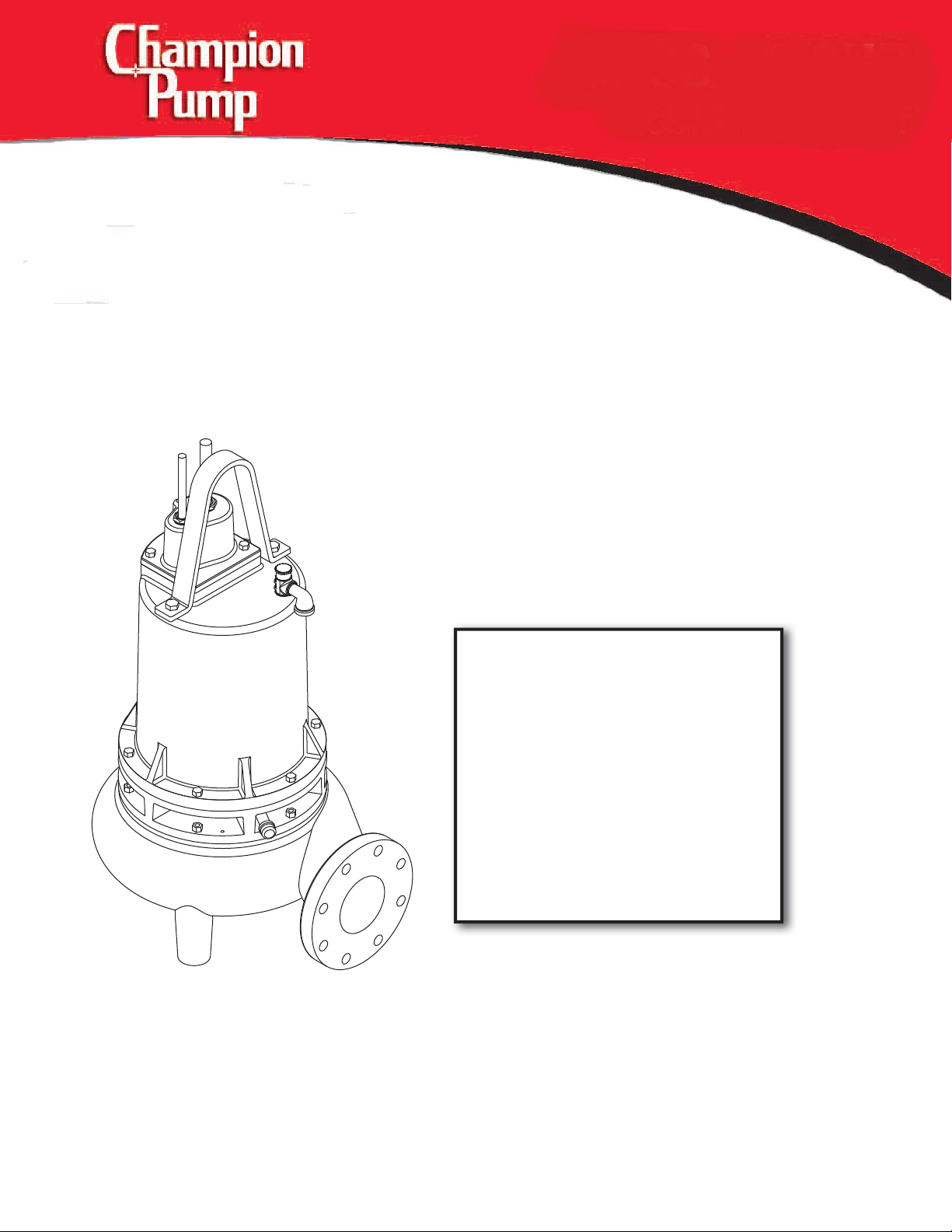
CP4NC
4.5, 7.5, 11.3 & 15HP
Submersible Non-Clog
No: CP4NC - 04/15
INSTALLATION, SERVICE & PARTS MANUAL
CP4NC4524, CP4NC4534,
CP4NC4544, CP4NC4564,
CP4NC4564, CP4NC7524,
www.championpump.com
CP4NC7534, CP4NC7544,
CP4NC7564, CP4NC11334,
CP4NC11344, CP4NC11364,
CP4NC15034, CP4NC15044
1750RPM, 60Hz
Champion Pump Company, Inc • P.O. Box 528 • Ashland, OH 44805
Phone 419-281-4500 • toll free 800-659-4491 • fax 419-616-1100
1

General Safety Information
Before installation, read the following
instructions carefully. Failure to follow
instruction and Safety information could
cause serious bodily injury, death and/or
property damage. Each Champion pump is
individually factory tested to insure proper
performance. Closely following these
instructions will eliminate potential operating
problems, assuring years of trouble-free
service.
“Danger” indicates
an imminenty
hazardous situation which, if not avoided,
WILL result in death or serious injury.
“Warning” indicates
an imminenty
hazardous situation which, if not avoided,
MAY result in death or serious injury.
“Caution” indicates
an potentially
hazardous situation which, if not avoided,
MAY result in minor or moderate injury.
IMPORTANT - Champion Pump is not
responsible for losses, injury or death
resulting from failure to observe these
safety precautions, misuse, abuse or
misapplication of pumps or equipment.
ALL RETURNED
PRODUCTS MUST BE
CLEANED, SANITIZED,
OR RECONTAMINATED
PRIOR TO SHIPMENT, TO
INSURE EMPLOYEES WILL NOT BE EXPOSED
TO HEALTH HAZARDS IN HANDLING SAID
MATERIAL. ALL APPLICABLE LAWS AND
REGULATIONS SHALL APPLY.
Installation, wiring,
and junction
connections must be in accordance with
the National Electric Code and all applicable
state and local codes. Requirements may
vary depending on usage and location.
Installation and
servicing is to be
conducted by quali ed personnel only.
Keep clear of suction
and discharge
openings. Do not insert ngers in
pump with power connected.
Always wear eye
protection when
working on pumps. Do not wear loose
clothing that may become entangled in
moving parts
Pumps build up heat
and pressure during
operation. Allow time
for pumps to cool
before handling or
servicing.
This pump is not
intended for use
in swimming pools or water
installations where human
contact with pumped uid.
Risk of electric shock.
To reduce risk of
electric shock, always disconnect
pump from power source before
handling. Lock out power & tag.
Do not us these
pumps in water
over 104˚F. Do not exceed manufactures
recommended maximum performance, as
this could cause the motor to overheat.
Do not lift, carry or
hang pump by the
electrical cables. Damage to the
electrical cables can cause shock,
burnes or death. Never handle
connected power cords with wet hands. Use
appropriate lifting device.
Sump and sewage
pumps often handle
materials which could cause illness or disease.
wear adequate protective clothing when
working on a used pump or piping. Never
enter a basin after it has been used.
Failure to permanently
ground the pump,
motor and controls before
connecting to power can cause
shock, burns or death.
These pumps are NOT
to be installed in
locations classi ed as hazardous in
accordance with the National
Electric Code, ANSI/NFPA 70.
IMPORTANT!
Prior to installation, record Model
Number, MFG Date, Amps, Voltage, Phase
and HP, from pump name plate for future
reference. Also record the Voltage and
Current Readings at Startup:
1 Phase Models
Amps: Volts:
3 Phase Models
Amps L1-2: Volts L1-2:
Amps L2-3: Volts L2-3:
Amps L3-1: Volts L3-1:
Model Number: ____________________
MFG Date: ____________
PHASE: ______ HP: _________________
Other brand and product names are trademarks or registered trademarks of their respective holders.
Alteration Rights Reserved. 1/12
Champion Pump Company, Inc • P.O. Box 528 • Ashland, OH 44805
2
Phone 419-281-4500 • toll free 800-659-4491 • fax 419-616-1100
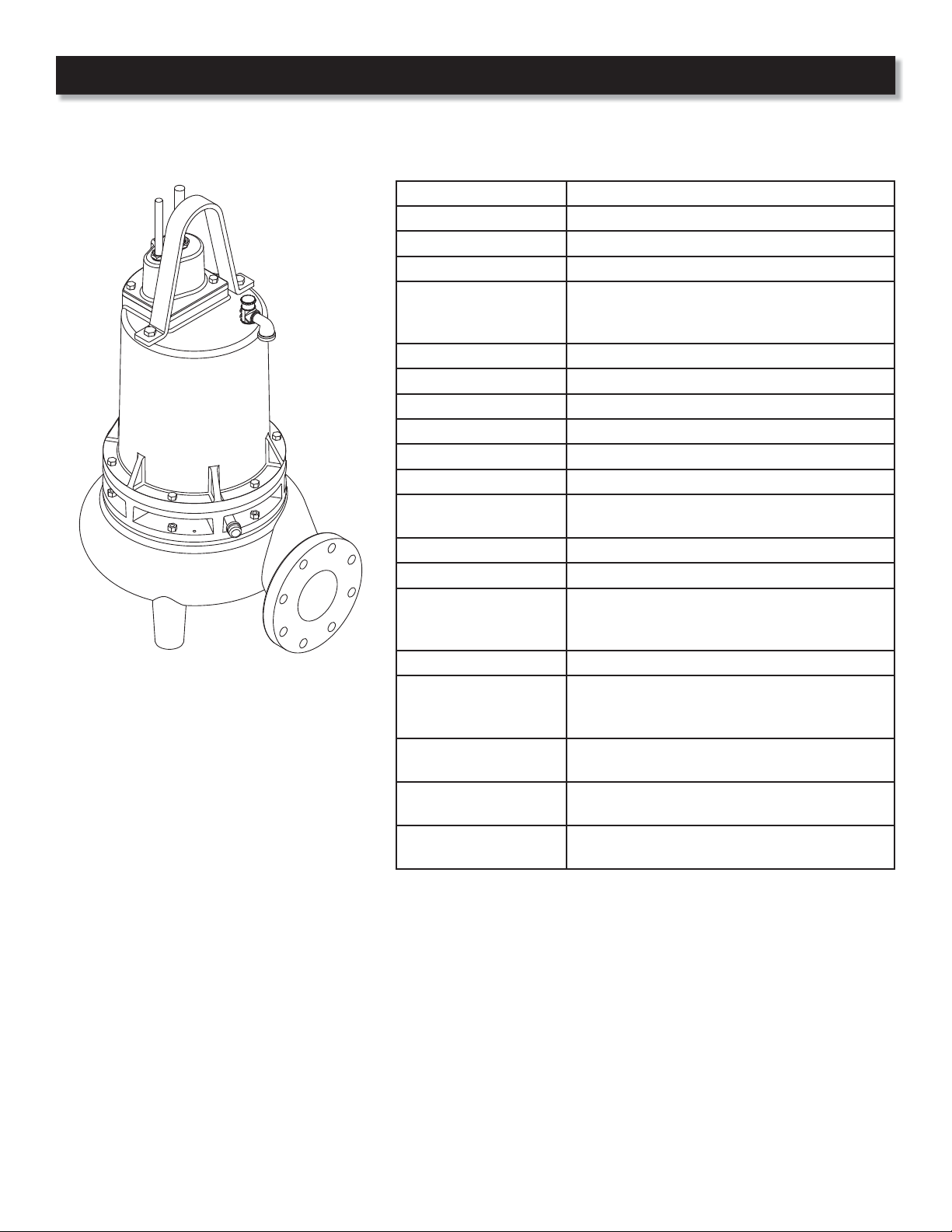
Speci cations
DISCHARGE 4” 125 lb., Flange Horizontal
LIQUID TEMPERATURE 104°F Continuous
MOTOR HOUSING Cast Iron, Class 30
VOLUTE Cast Iron, Class 30
2 vane open type with pump out vanes on back
IMPELLER
SOLIDS HANDLING 3” spherical
SHAFT Stainless steel
SEALPLATE Cast Iron, Class 30
SQUARE RINGS Buna-N
HARDWARE Stainless steel
PAINT Air dry enamel
SEAL
UPPER BEARING Single row, ball, oil lubricated
LOWER BEARING Double row, ball, oil lubricated
POWER CORD
MOTOR Class F Insulation, Oil Filled
SINGLE PHASE
THREE PHASE
MOISTURE SENSOR
TEMPERATURE
SENSOR
side, Dynamically balanced, ISO G6.3, Cast Iron,
Class 30
Double mechanical, Oil Filled pressure
equalized reservoir, Silicon Carbide outer seal
25 Ft. Cord. Epoxy sealed housing with
secondary Pressure grommet for sealing and
strain relief.
Capacitor Start/Capacitor Run.
Requires Starter/Panel which includes
capacitors and overload protection.
230/460 Volt. Dual Voltage.Requires overload
protection to be included in control panel.
Normally open (N/O),
requires relay in control panel
Normally closed (N/C),
requires relay in control panel
Champion Pump Company, Inc • P.O. Box 528 • Ashland, OH 44805
Phone 419-281-4500 • toll free 800-659-4491 • fax 419-616-1100
3
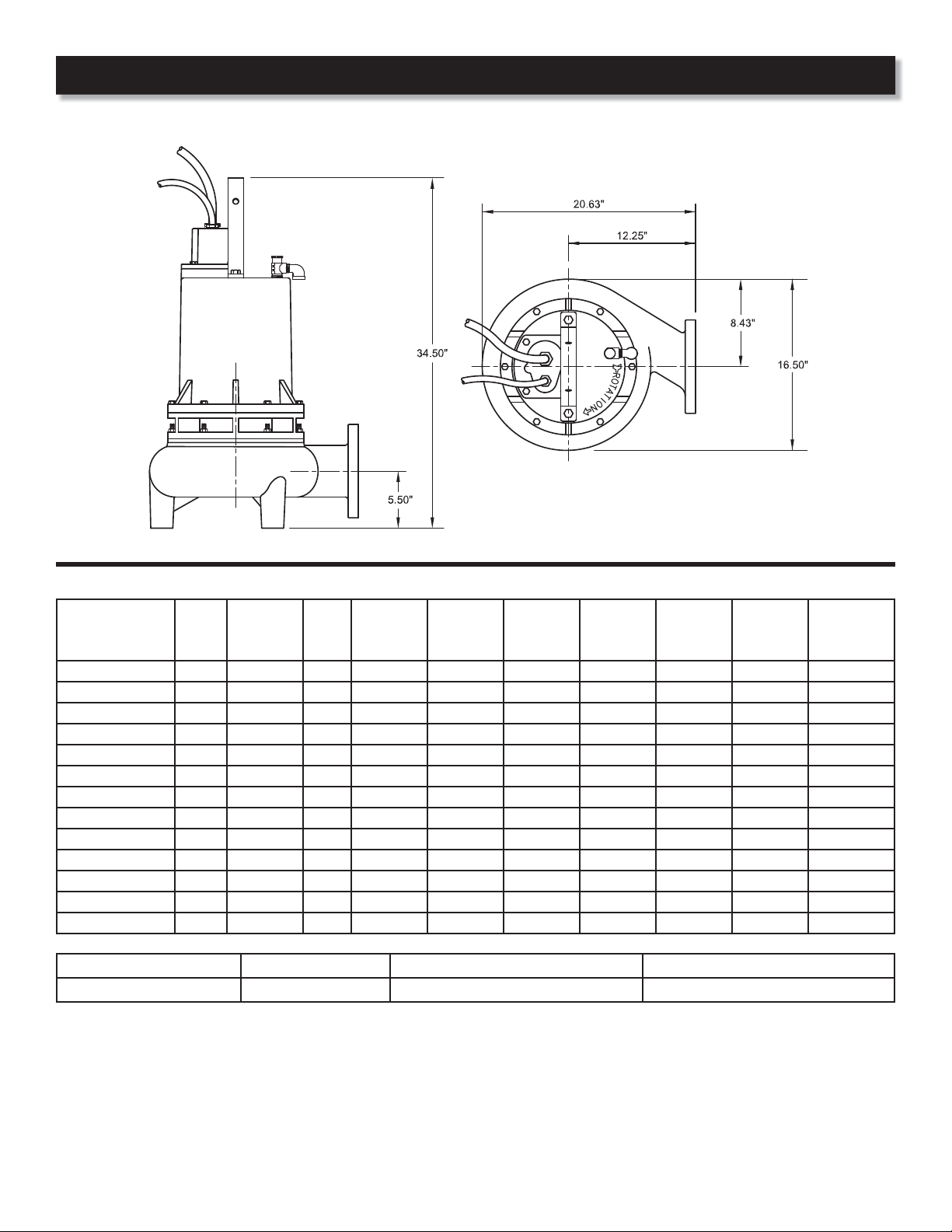
Speci cations & Dimensions
MODEL HP Volt/PH Hz
CP4NC4524 4.5 230/1 60 1750 A 26.0 59.0 10/4 SOW 0.750
CP4NC4534 4.5 230/3 60 1750 E 18.2 56.0 10/4 SOW 0.750
CP4NC4544 4.5 460/3 60 1750 E 9.1 28.0 10/4 SOW 0.750
CP4NC4564 4.5 200/3 60 1750 C 20.9 48.6 10/4 SOW 0.750
CP4NC7524 7.5 230/1 60 1750 A 39.0 96.0 6/4 SOW 1.060
CP4NC7534 7.5 230/3 60 1750 D 26.8 80.0 8/4 SOW 0.830
CP4NC7544 7.5 460/3 60 1750 D 13.4 40.0 8/4 SOW 0.830
CP4NC7564 7.5 200/3 60 1750 B 30.8 69.5 8/4 SOW 0.830
CP4NC11334 11.3 230/3 60 1750 D 28.0 126.0 8/4 SOW 0.830
CP4NC11344 11.3 460/3 60 1750 D 14.0 63.0 8/4 SOW 0.830
CP4NC11364 11.3 200/3 60 1750 B 32.2 109.5 8/4 SOW 0.830
CP4NC15034 15 230/3 60 1750 D 38.0 160.0 6/4 SOW 1.060
CP4NC15044 15 460/3 60 1750 D 19.0 80.0 6/4 SOW 1.060
MODELS START RELAY START CAPACITOR RUN CAPACITOR
CP4NC4524 & CP4NC7524 MARS 64 233-280 mfd - 250 volt, MARS 11053 60 mfd - 370 volt, MARS 12087
Winding resistance ± 5% at terminal block. Rated operation at ± 10% voltage at motor.
Moisture/Temperature sensor cable for all models is 18/5 SOW, 0.476 inch O.D.
RPM
(Nom)
NEMA
Start
Code
Full Load
Amps
Locked
Rotor
Amps
Cord
Size
Cord
Typ e
Cord O.D
inch
(*) IMPORTANT! - These pumps require a control panel with start, run capacitors and relay. Capacitor kits which include Start &
Run capacitors and start relay, are available if a Champion control panel is not used. See page 14.
Champion Pump Company, Inc • P.O. Box 528 • Ashland, OH 44805
4
Phone 419-281-4500 • toll free 800-659-4491 • fax 419-616-1100
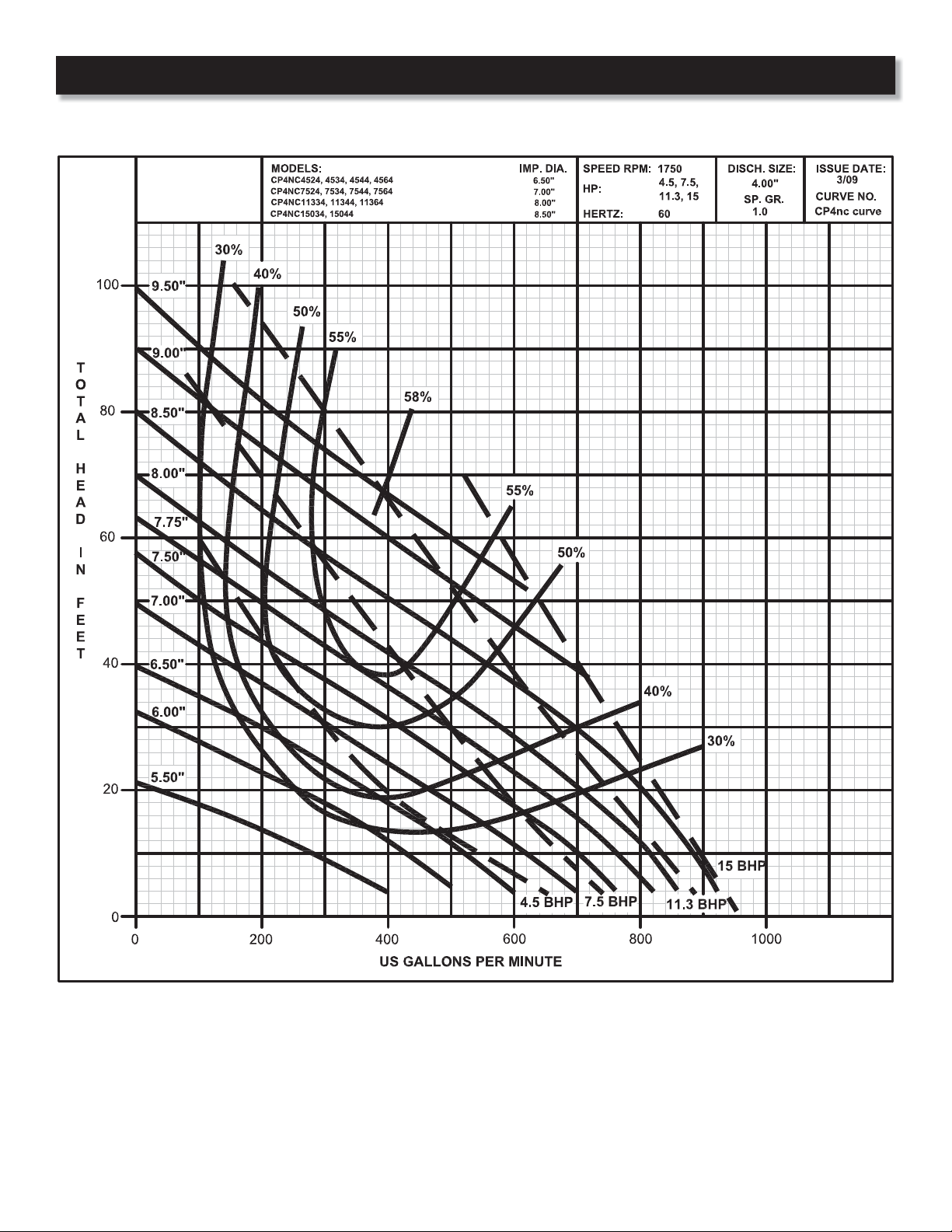
Performance
Champion Pump Company, Inc • P.O. Box 528 • Ashland, OH 44805
Phone 419-281-4500 • toll free 800-659-4491 • fax 419-616-1100
5
Receiving & Installation
Receiving Inspection
Upon receiving the pump, it should be
inspected for damage or shortages.
If damage has occurred, le a claim
immediately with the company that
delivered the pump. If the manual is
removed from the packaging, do not
lose or misplace.
Storage
Any product that is stored for a period
longer than six (6) months from the
date of purchase should be bench
tested prior to installation. A bench
test consists of, checking the impeller
to assure it is free turning and a run
test to assure the motor (and switch
if provided) operate properly. Do not
pump out of liquid.
Controls
Manual models require a separate
approved pump control device or panel
for automatic operation. Be sure the
electrical speci cation of the control
selected properly match the electrical
speci cations of the pump.
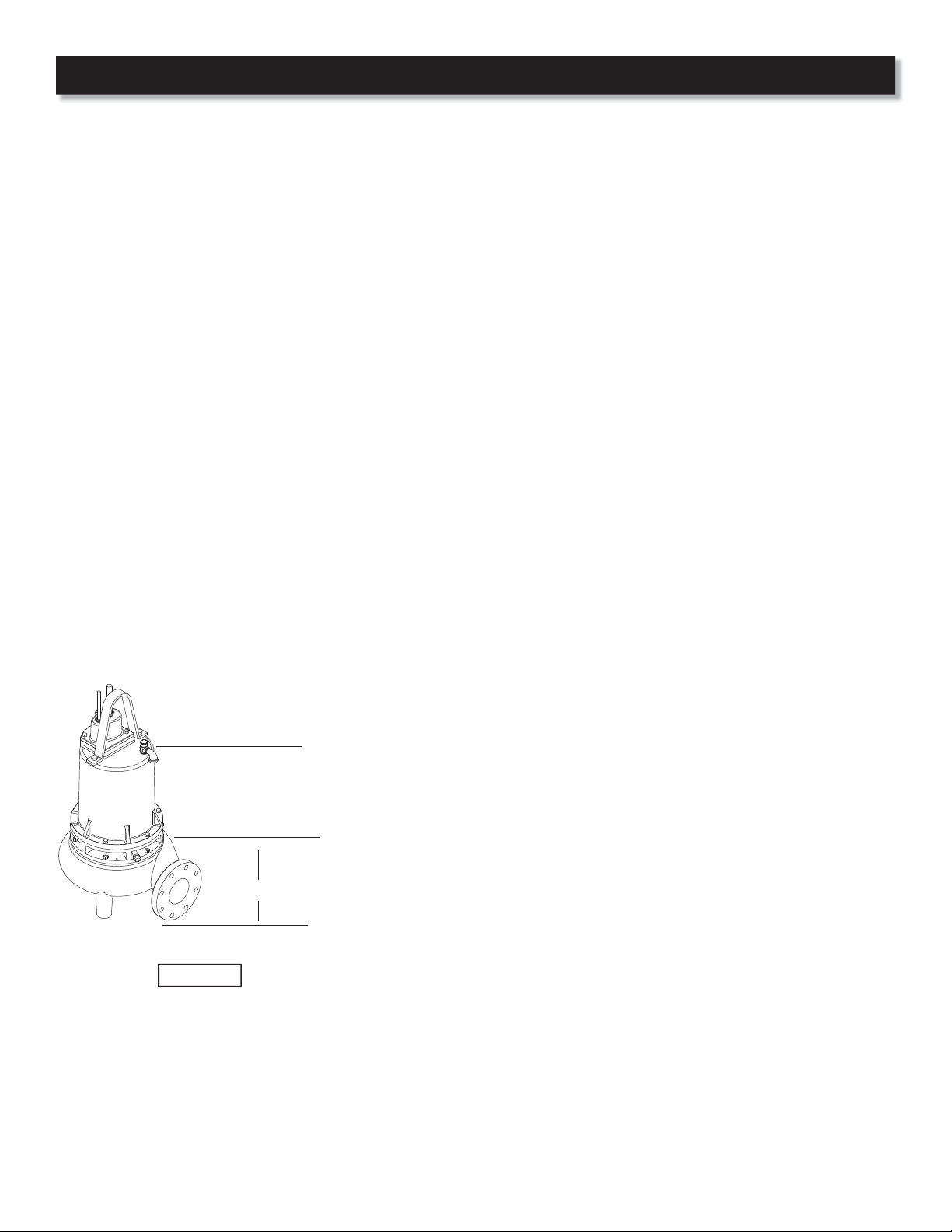
Recommended
Submergence Level
Minimum
Submergence Level
10”
Bottom of Feet
Figure 1
Submergence
The pump should always be operated in
the submerged condition. The minimum
sump liquid level should never be less than
above the pump’s volute (See Figure 1).
Installation
These pumps are recommended for
use in a sump, basin or lift station.
The sump, basin or lift station shall be
sealed and vented in accordance with
local plumbing codes. This pump is
designed to pump sewage, e uent
or wastewater, nonexplosive and
noncorrosive liquids and shall NOT
be installed in locations classi ed as
hazardous in accordance with the
National Electrical Code (NEC) ANSI/
NFPA 70 or Canadian Electric Code
(CEC). The pump should never be
installed in a trench, ditch, or hole with
a dirt bottom. The legs will sink into
the dirt and the suction will become
plugged.
The installation should be at a su cient
depth to ensure that all plumbing is
below the frost line. If this is not feasible,
remove the check valve and size the
basin to accommodate the additional
back ow volume.
Pumps are most commonly installed
in simplex, duplex or triplex stations or
basins with a slide rail system, which
allows the pump(s) to be installed or
removed without requiring personnel to
enter the station, or resting on the basin
oor.
Discharge Piping
Discharge piping should be as short as
possible and sized no smaller than the
pump discharge. Do not reduce the
discharge pipe size below that which
is provided on the pump.
Both a check valve and a shut-o valve
are recommended for each pump. The
check valve is used to prevent backow
into the sump. The shut-o valve is used
to manually stop system ow during
pump servicing.
Liquid Level Controls
The level control(s) should be mounted
on the discharge piping, a cable rack or
oat pole. The level control should have
adequate clearance so it cannot hang
up in it’s swing and that the pump is
completely submerged when the level
control is in the “O ” mode. By adjusting
the cord tether the control level can be
changed. One cycle of operation should
be observed, so that any potential
problems can be corrected.
It is recommended that the level control
oat should be set to insure that the
liquid in the sump never drops below the
top of the motor housing or a minimum
level of 10 inches above the basin oor.
Electrical Connections
Power/control cables:
The power/control cables mounted to
the pump must not be modied in any
way except for shortening to a specic
application. Any splice between the
pump and the control panel must be
made in accordance with the electric
codes. It is recommended that a junction
box, if used, be mounted outside the
sump or be of at a minimum Nema
4 construction if located within the
wet well. DO NOT USE THE POWER/
CONTROL CABLES TO LIFT PUMP.
Always rely upon a Certi ed Electrician
for installation.
Overload Protection:
Single Phase - The stator in-winding
overload protector used is referred to
as an inherent overheating protector
and operates on the combined e ect
of temperature and current. This means
that the overload protector will trip out
and shut the pump o if the windings
become too hot, or the load current
passing through them becomes too high.
Champion Pump Company, Inc • P.O. Box 528 • Ashland, OH 44805
6
Phone 419-281-4500 • toll free 800-659-4491 • fax 419-616-1100
 Loading...