

Page 1
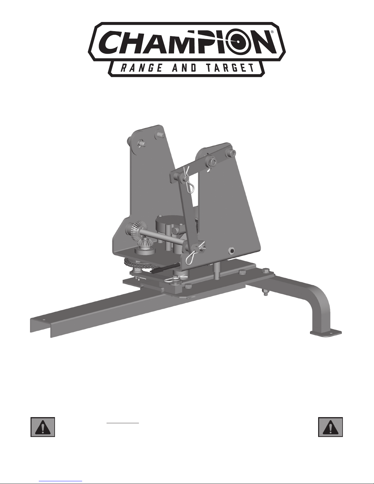
WOBBLE BIRD® ELECTRONIC TRAP BASE
OWNER’S INSTRUCTION MANUAL
WARNING: Traps can cause serious injury or death !
Thoroughly read instructions and safety information
before assembling, installing or operating Wobble Bird !
Keep this instruction manual for future reference.
PART NO. 40924
Page 2

Page 3
TABLE OF CONTENTS PAGE
Safety Instructions 1
Wobble Bird Base Parts List /Tools Required for Assembly 2
Assembly (for use with Workhorse Trap and included Tripod Stand) 3-5
Assembly of Workhorse Trap onto Wobble Bird Base with Tripod Stand 6-8
Assembly of Wobble Bird Base with Trap Taxi (not included) 9-12
Assembly of WheelyBird Trap onto Wobble Bird Base with Trap Taxi (not included) 13-15
Wobble Bird Operation (Standard Dual Axis Motion) 16
Wobble Bird Operation (Alternate Single Axis Motion: Left/Right only) 17-21
Wobble Bird Operation (Alternate Single Axis Motion: Up/Down only) 22-23
Troubleshooting 24
Warranty Statement 25
SAFETY INSTRUCTIONS
WARNING: The Wobble Bird Base is designed for mounting the Champion Workhorse or Wheelybird
traps only. Do not use your wobble bird base for any other purpose. Never attach or tow the base by
vehicle.
• The Wobble Bird Base is to be used in conjunction with the Champion Workhorse or Wheelybird trap thrower.
Mounting any other thrower to the base can cause serious personal injury and/or potential damage to base
and trap.
• Always disconnect the trap’s tension spring and/or power source prior to mounting it to the base. Never
attach a trap to the base while the throwing arm is in the cocked position.
• Use caution when moving your Wobble Bird Base. Always disconnect the tension spring and power source
from the trap and Wobble Bird Base before movement. Always secure the base from movement before
activating trap. Avoid rough terrain and chock wheels if necessary. Never re trap while the base is being
relocated or transported.
• Stand at rear of trap when in use. Stay clear of throwing arm at all times. Do not leave trap cocked and
unattended.
• Use only in a controlled environment where you can be certain no one is in the area who could be in the line
of the trap’s trajectory or line of re. Never use when children are in the area.
Congratulations on the purchase of your CHAMPION Wobble Bird Base !
1. Unpack components from the box and identify all parts before proceeding with any assembly.
2. Carefully inspect the carton and Wobble Bird Electronic Trap Base to be sure that damage hasn’t occurred during
shipping. If damage is found to have occurred during shipping do not use Wobble Bird Electronic Trap Base and
report any damage found immediately to the shipper.
3. Carefully remove trap assembly and all other components from cardboard shipping box and other smaller boxes.
Remove all hardware from bags.
4. Ensure that all parts were included in shipping container and cartons. If any parts are missing do not use the
Wobble Bird Electronic Trap Base and call the CHAMPION TRAPS AND TARGETS Customer Service Department at
(800) 379-1732 to obtain replacement parts.
1
Page 4
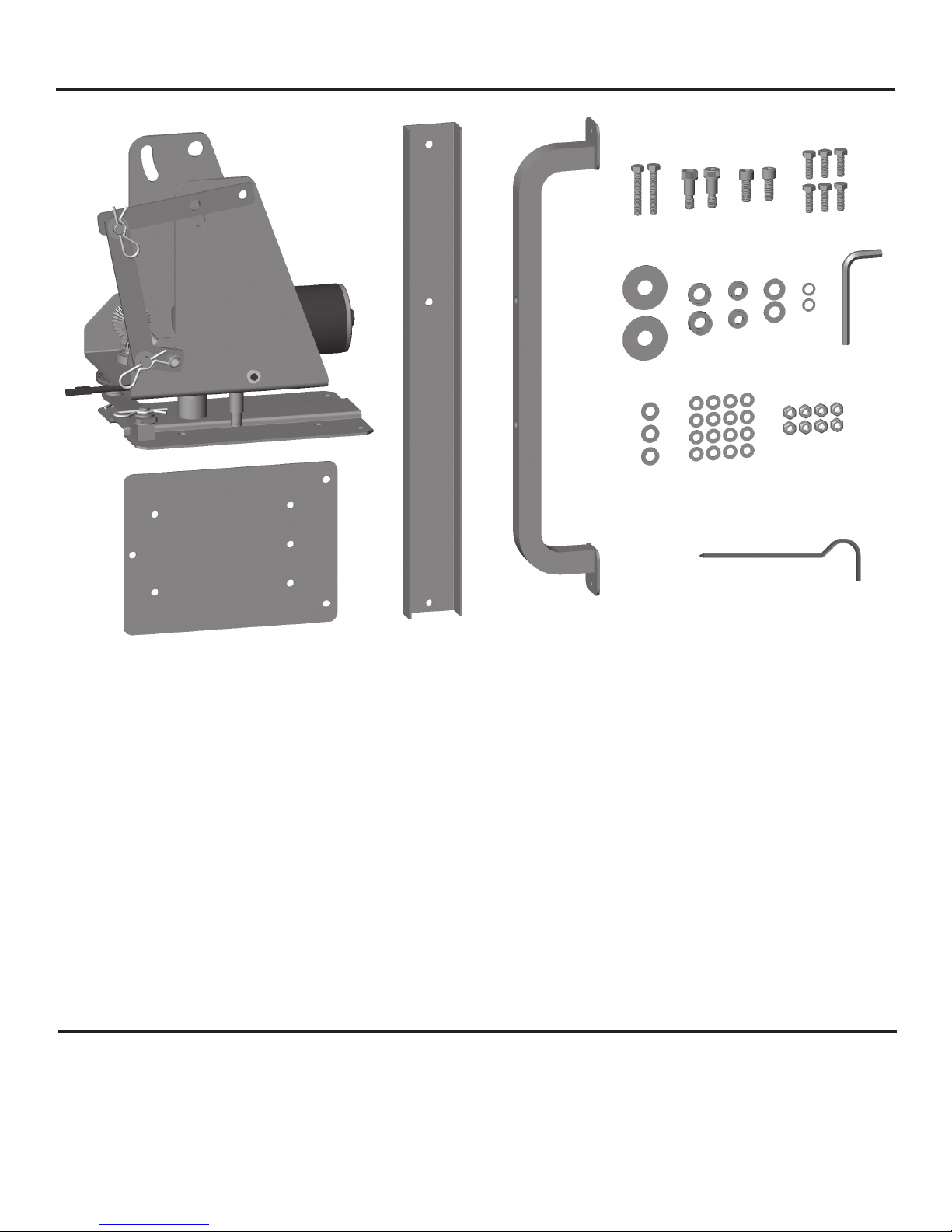
Wobble Bird Base Parts List
3 4
1
5
6
10
7
8
15
14
13
12
11
9
18
16
17
2
19
1. Wobble Bird Sub-Assembly
2. Wobble Bird Bracket
3. Stand, Rear Leg
4. Stand, Front Legs
5. 8mm x 45mm Hex Head Bolt (2)
6. M10 Shoulder Bolt (2)
7. M10 x 25mm Socket Head Bolt (2)
8. M8 x 25mm Hex Head Bolt (6)
9. Large Washer (2)
10. Bolt Cup, Small
11. Bolt Cup, Large
12. Bushing (2)
13. M12 Washer (2)
14. 10mm Lock Washer (2)
15. 8mm Hex Key
16. M10 Washer (3)
17. M8 Washer (16)
18. M8 Locknut (8)
19. Ground Stakes (3)
Tools Required for Assembly (Listed in order of usage)
• 13mm wrench or adjustable wrench (2pcs)
• 8mm Hex Key (Provided)
• 10mm wrench or adjustable wrench (used for Workhorse only)
2
Page 5
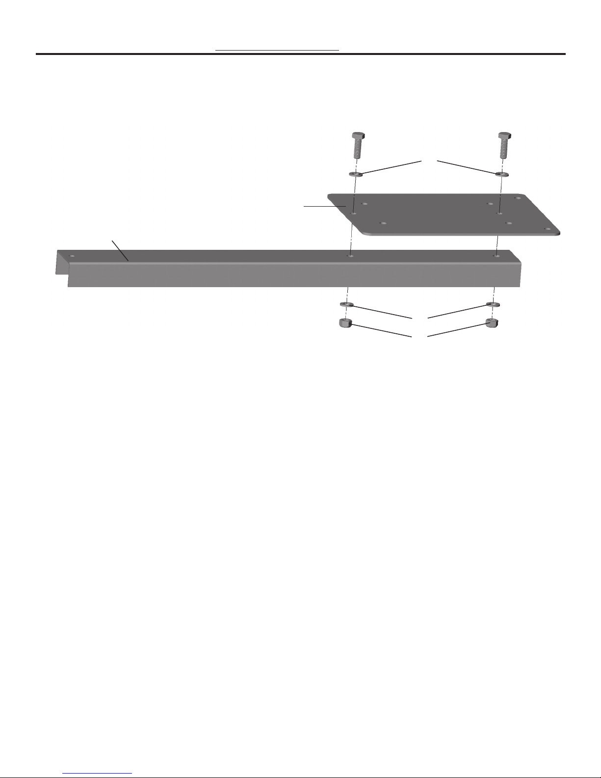
Assembly (for use with Workhorse Trap and included Tripod Stand)
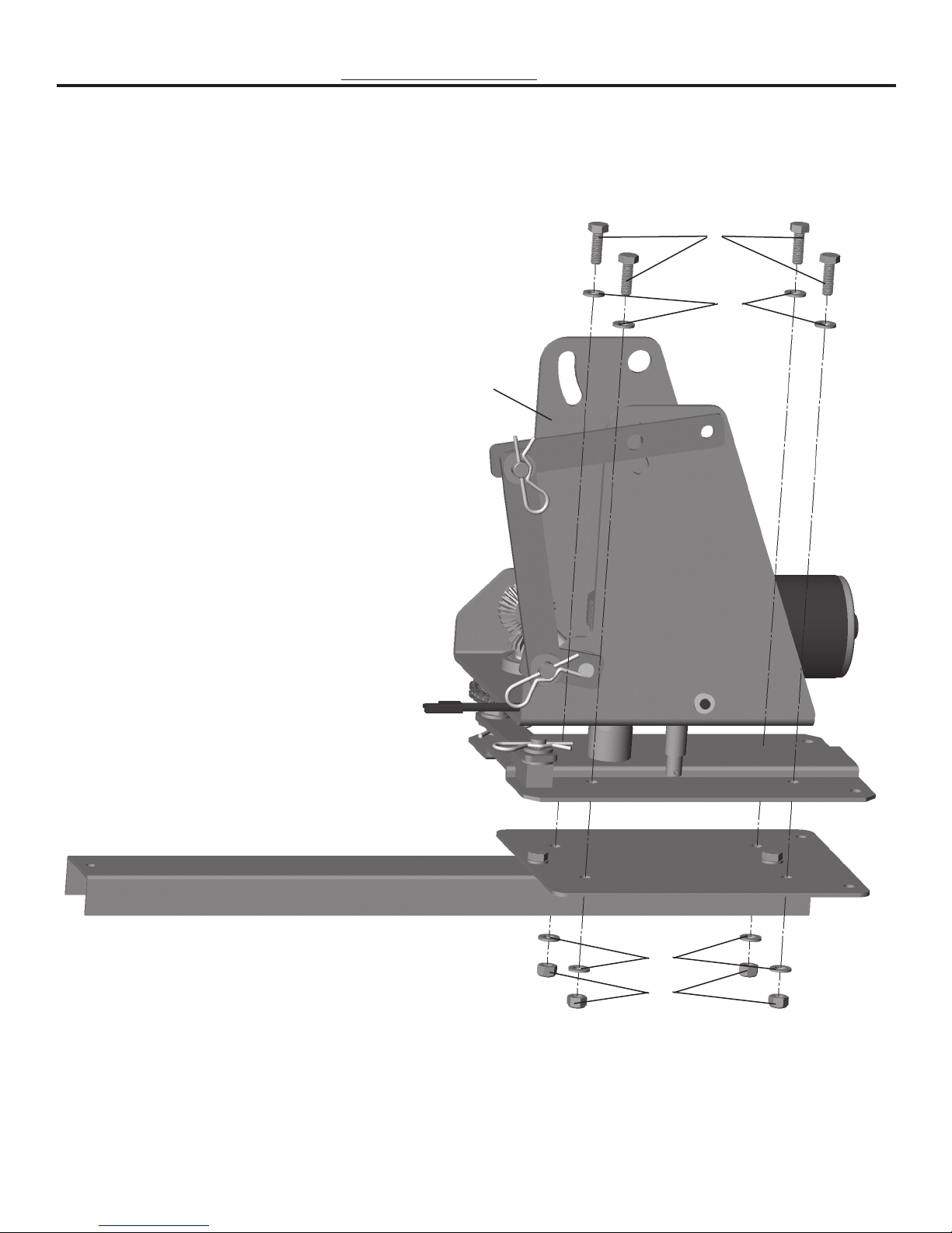
STEP 1: Attach Wobble Bird Bracket (2) to Stand, Rear Leg (3) using two M8 x 25mm Hex Head Bolts
(8), four M8 Washers (17), and two M8 Locknuts (18).
8 8
STEP 1
17
2
3
17
18
3
Page 6
Assembly (for use with Workhorse Trap and included Tripod Stand)
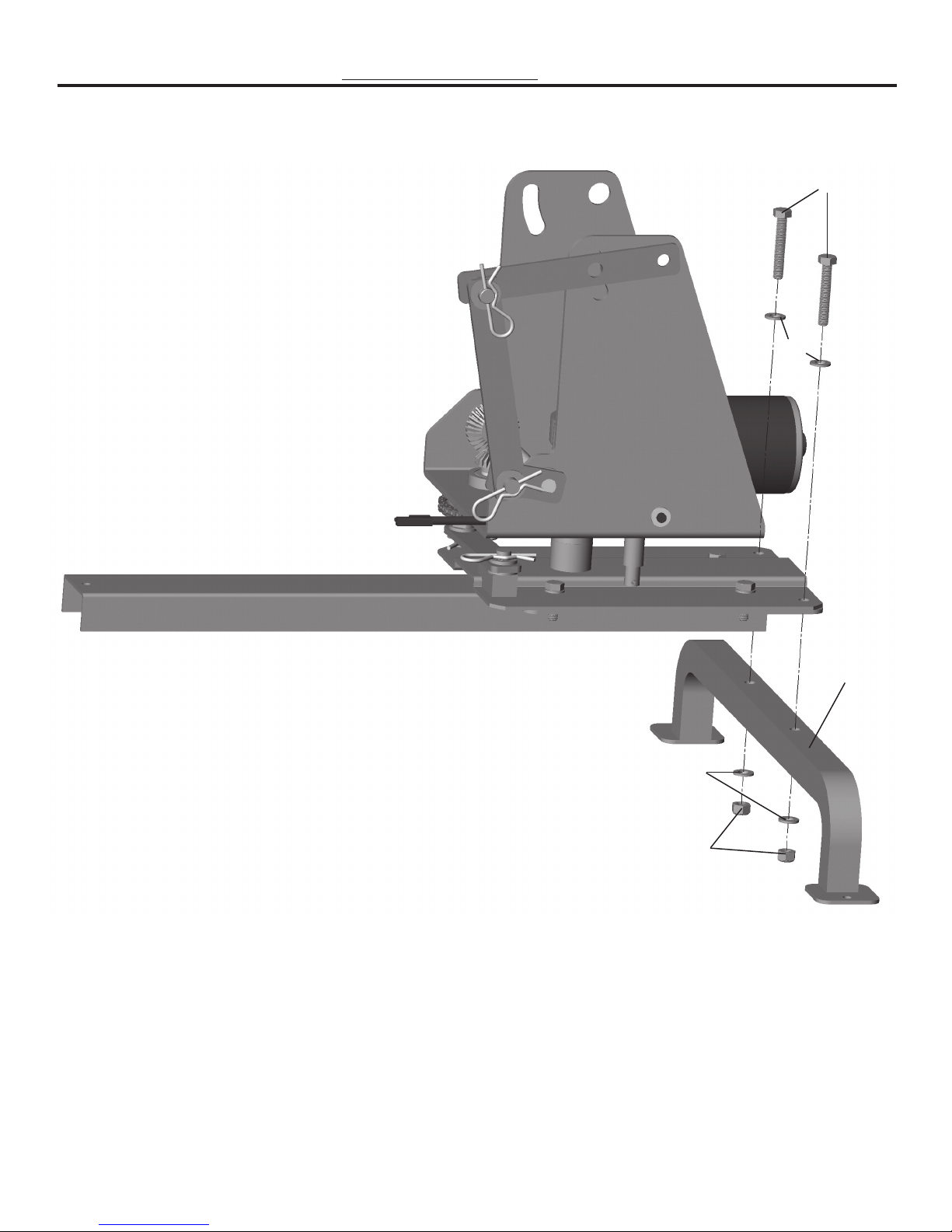
STEP 2: Attach Wobble Bird Sub-Assembly (1) to assembly from previous step using four M8 x 25mm
Hex Head Bolts (8), eight M8 Washers (17), and four M8 Locknuts (18).
8
17
1
STEP 2
17
18
4
Page 7
Assembly (for use with Workhorse Trap and included Tripod Stand)
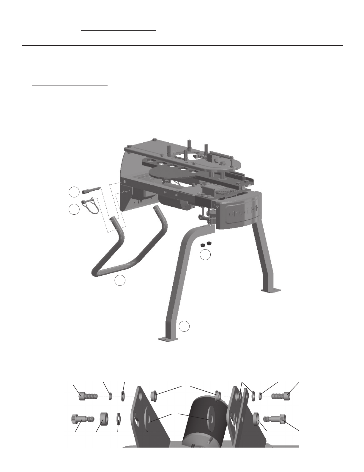
STEP 3: Attach Stand, Front Legs (4) to assembly from previous step using two 8mm x 45mm Hex
Head Bolt (5), four M8 Washers (17), and two M8 Locknuts (18).
5
17
STEP 3
17
18
4
5
Page 8
Assembly of Workhorse Trap onto Wobble Bird Base
with included Tripod Stand
1. Before installing a trap on the Wobble Bird Base, safely conduct a safe release on the trap and then safely remove the
mainspring. Refer to your trap’s manual regarding the proper procedure for safe release and removal of mainspring.
If you are no longer in possession of the trap manual, do not continue assembly or use of the unit and contact
Champion customer service at (800) 379-1732 or look for a link to the manual on the web page for your trap at:
www.championtarget.com.
2. Several components on the Workhorse Trap will need to be removed from the trap.
a. To disassemble the trap, remove both Wire Lock Pins (F4).
b. Using a 10mm wrench, remove both Arm Path Tube Studs (F3). The Rear Leg (F6) can now be removed from
the trap.
c. Re-install both Arm Path Tube Studs (F3) using a 10mm wrench.
d. Using a 13mm wrench, remove both Front Legs (F5).
F3
F4
F1
F6
F5
3. The following hardware conguration (below) shall be used when installing a WORKHORSE TRAP to the Wobble
Bird Base. Installation steps are shown in detail on the following pages. If you will be installing a WHEELYBIRD, see
page 13 for proper hardware assembly.
7
14
16
12
16
14
7
6
11
13
9
10 6
13
6
Page 9
Assembly of Workhorse Trap onto Wobble Bird Base
with included Tripod Stand
4. Installation of left side hardware:
a. With the Bushing (12) resting in the Wobble Bird Sub-Assembly (1) hole, have another person help you
carefully lower the trap into position. (Note: Wheel bearing grease or petroleum jelly can be used to keep the
Bushing (12) in place during assembly. Use only enough to hold it in place. Remove excess when step is complete.)
b. Once the trap is in position, install one 10mm Lock Washer (14) and one M10 Washer (16) onto the M10 x
25mm Socket Head Bolt (7) as shown.
c. Insert the M10 x 25mm Socket Head Bolt (7) with washers from previous step through the Wobble Bird Base
Sub-Assembly (1), Bushing (12) and into the Workhorse chassis as shown. Do not tighten bolt completely.
d. Slide the Large Washer (9) between the Workhorse trap chassis and the Wobble Bird Sub-Assembly (1)
ensuring it rests over the pressed in nut on the Workhorse Chassis.
e. Install one Bolt Cup, Large (11) and one M12 Washer (13) onto the M10 Shoulder Bolt (6) as shown.
f. Insert the M10 Shoulder Bolt (6) with Bolt Cup, Large (11) and M12 Washer (13) from previous step through
the Wobble Bird Base Sub-Assembly (1), Large Washer (9) and into the Workhorse chassis as shown. Do not
tighten bolt completely.
16
12
14
7
6
11
9
13
1
7
Page 10

Assembly of Workhorse Trap onto Wobble Bird Base
with included Tripod Stand
5. Installation of right side hardware:
a. With thrower held up by the other side, insert Bushing (12) from inside out and hold trap in position. (Note:
Wheel bearing grease or petroleum jelly can be used to keep the Bushing (12) in place during assembly. Use only
enough to hold it in place. Remove excess when step is complete.)
b. Once the trap is in position, install one 10mm Lock Washer (14) and one M10 Washer (16) onto the M10 x
25mm Socket Head Bolt (7) as shown.
c. Insert the M10 x 25mm Socket Head Bolt (7) with washers from previous step through the linkage bracket,
M10 Washer (16), Wobble Bird Base Sub-Assembly (1), Bushing (12) and into the Workhorse chassis as shown.
Do not tighten bolt completely.
d. Slide the Large Washer (9) between the Workhorse trap chassis and the Wobble Bird Sub-Assembly (1)
ensuring it rests over the pressed in nut on the Workhorse Chassis.
e. Install one Bolt Cup, Small (10) onto the M10 Shoulder Bolt (6) as shown.
f. Insert the M10 Shoulder Bolt (6) with Bolt Cup, Small (10) from previous step through the linkage bracket,
M12 Washer (13), Wobble Bird Base Sub-Assembly (1), Large Washer (9) and into the Workhorse Trap chassis
as shown.
g. Tighten all four mounting bolts completely using the provided 8mm hex key.
6. See page 16 for Wobble Bird Operation.
WARNING: Failure to tighten these bolts and to follow all instructions carefully can result in serious injury
or death.
16
1612
14
7
6
9
10
13
1
Note: some linkage components
have been removed from this
image for greater clarity.
8
Page 11

Assembly of Wobble Bird Base with Trap Taxi (not included)
NOTE: Not all hardware provided with the Wobble Bird Base is used when attaching Trap Taxi components.
1. Using two 13mm wrenches (or adjustable wrenches), attach Wobble Bird Sub-Assembly (1) to Wobble Bird Bracket
(2) using two M8 x 25mm Hex Head Bolts (8), four M8 Washers (17), and two M8 Locknuts (18) as shown.
8
17
1
2
17
18
9
Page 12

Assembly of Wobble Bird Base with Trap Taxi (not included)
Note: If your Trap Taxi is assembled and a trap is attached, it will be necessary to safely conduct a safe release on the
trap and safely remove the main spring. Refer to your trap’s manual regarding the proper procedure for safe release
and removal of mainspring. If you are no longer in possession of the trap manual, do not continue assembly or use of
the unit and contact Champion customer service at (800) 379-1732 or look for a link to the manual on the web page for
your trap at: www.championtarget.com.
2. Remove the trap from the Trap Taxi and set it aside. Disassemble the trap taxi until you have an axle assembly and a
handle assembly as seen on page 10 and page12 respectively. If your Trap Taxi is not assembled, it will be necessary
to use the instructions provided with the Trap Taxi to build the two required assemblies.
3. Using two 13mm wrenches (or adjustable wrenches), attach the Trap Taxi axle assembly (not included) to the
assembly from the previous step using two M8 x 25mm Hex Head Bolts (8), four M8 Washers (17), and two M8
Locknuts (18) as shown.
8
17
17
18
10
Page 13

Assembly of Wobble Bird Base with Trap Taxi (not included)
4. In order to properly install the hardware in step 4, it is necessary to temporarily disconnect the horizontal motion
linkage on the Wobble Bird Base.
a. Remove hitch pin.
b. Retain bushing and washer while sliding clevis pin downward.
a
b
11
Page 14

Assembly of Wobble Bird Base with Trap Taxi (not included)
5. Installation of Trap Taxi hardware:
a. Using two 13mm wrenches (or adjustable wrenches), attach the Trap Taxi handle assembly (not provided) to
the assembly from the previous step using two 8mm x 45mm Hex Head Bolt (5), four M8 Washers (17), and
two M8 Locknuts (18).
b. It will be necessary to rotate the upper portion of Wobble Bird Base counterclockwise with respect to the
lower portion until the sprocket is clear enough that the rearmost bolt can be easily inserted through the
assembly.
c. Once all hardware is attached and secure (tighten all nuts and bolts securely), reattach the horizontal motion
linkage on the Wobble Bird Base.
5
17
17
18
12
Page 15

Assembly of WheelyBird Trap onto Wobble Bird Base
with Trap Taxi (not included)
NOTE: Not all hardware provided with the Wobble Bird Base is used when attaching a WheelyBird trap.
1. Before installing a trap on the Wobble Bird Base, safely conduct a safe release on the trap and then safely remove
the mainspring. Refer to your trap’s manual regarding the proper procedure for safe release and removal of
mainspring. If you are no longer in possession of the trap manual, do not continue assembly or use of the unit
and contact Champion customer service at (800) 379-1732 or look for a link to the manual on the web page for
your trap at: www.championtarget.com.
2. The following hardware conguration (below) shall be used when installing a WHEELYBIRD TRAP onto
the Wobble Bird Base. Installation steps are shown in detail on the following pages. If you will be installing a
WORKHORSE, see page 6 for proper hardware assembly.
7 14
6 111213
16
12
13
14 716
10
6
13
Page 16

Assembly of WheelyBird Trap onto Wobble Bird Base
with Trap Taxi (not included)
3. Installation of left side hardware:
a. Using a second person to help you, with them carefully holding the trap in position, install one 10mm
Lock Washer (14), one M10 Washer (16) and one Bushing (12) onto the M10 x 25mm Socket Head Bolt (7)
as shown.
b. Insert the M10 x 25mm Socket Head Bolt (7) with washers and bushing from previous step through the
Wobble Bird Base Sub-Assembly (1) and into the WheelyBird chassis as shown. Do not tighten bolt
completely.
c. Install one Bolt Cup, Large (11) and one M12 Washer (13) onto the M10 Shoulder Bolt (6) as shown.
d. Insert the M10 Shoulder Bolt (6) with Bolt Cup, Large (11) and M12 Washer (13) from previous step through
the Wobble Bird Base Sub-Assembly (1) and into the WheelyBird chassis as shown. Do not tighten bolt
completely.
14
16
12
7
6
11
13
1
14
Page 17

Assembly of WheelyBird Trap onto Wobble Bird Base
with Trap Taxi (not included)
4. Installation of right side hardware:
a. With thrower held up by the other side, install one 10mm Lock Washer (14) and one M10 Washer (16) onto
the M10 x 25mm Socket Head Bolt (7) as shown.
b. Insert the M10 x 25mm Socket Head Bolt (7) with washers from previous step through the linkage bracket,
Bushing (12), Wobble Bird Base Sub-Assembly (1), and into the WheelyBird chassis as shown. Do not
tighten bolt completely.
c. Install one Bolt Cup, Small (10) onto the M10 Shoulder Bolt (6) as shown.
d. Insert the M10 Shoulder Bolt (6) with Bolt Cup, Small (10) from previous step through the linkage bracket,
M12 Washer (13), Wobble Bird Base Sub-Assembly (1), and into the WheelyBird chassis as shown.
e. Tighten all four mounting bolts completely using the provided 8mm hex key.
WARNING: Failure to tighten these bolts and to follow all instructions carefully can result in serious injury
or death.
12
16
13
1
10
14
7
6
15
Page 18

WOBBLE BIRD OPERATION (Standard Dual Axis Motion)
WARNING: Do not stand in front of trap or in the path of the throwing arm! Serious injury or death may
result! Never use unless the area is fully clear of other people and pets. Children should never be
allowed in the area. Any use of guns can be dangerous. It is your responsibility to use the Wobble Bird,
the attached trap, and your gun in accordance with law and common sense.
• The throwing arm path indicator on the trap must be mounted properly before using the trap and/or Wobble
Bird Base.
• Make sure that the Wobble Bird Base with trap is located to allow ample clearance around the machine and
provides safe access to the rear of the machine during operation. The machine must be located so that the
user has safe access to the rear to operate the on/o /safe release switch and reload the trap.
• Do not maneuver, transport, conduct repairs or maintenance on the Wobble Bird Base while it is connected
to power.
• Do not load, unload, turn on, turn o , or conduct a safe release on the trap while the Wobble Bird Base is
operating. Always turn the Wobble Bird Base o before performing any of these tasks.
Your Wobble Bird Base was shipped with the linkage positioned to provide both Left/Right motion and Up/Down
motion simultaneously (aka “Standard Dual Axis Motion”). See the next section for directions if you would prefer to
restrict motion to Left/Right only or Up/Down only (“Alternate Single Axis Motion”).
1. Once a safe and appropriate location has been selected for the Wobble Bird Base and Trap, use the provided ground
stakes (19) to secure the machine in place by inserting them in the holes located in the legs of the stand (bracket
support bar if using the Trap Taxi) and driving them into the ground (see images below).
2. With the power switch on the cord of the Wobble Bird Base in the “OFF” position, connect to a fully
charged 12V battery. Ensure all cords are safely away from the base and behind the trap.
3. Your Wobble Bird Base was shipped with the linkage positioned to provide both Left/Right motion
and Up/Down motion simultaneously (see pages 17-23 for alternate “single motion axis” setup and
operation).
a. Using the power switch located on the cord of the Wobble Bird Base, turn the power switch to
the “ON” position.
b. Verify proper function of Wobble Bird Base and ensure trap will only throw clays in a safe area
throughout the full range of motion.
c. Turn Wobble Bird Base off .
4. Make sure that the On/Off /Safe Release switch on the trap is in the “OFF” position and disconnect trap from power.
Reinstall the trap mainspring according to trap instructions.
5. Load clays into trap according to trap instructions.
6. When you are ready to throw clays:
a. Turn on the trap according to the trap instructions.
b. Turn on the Wobble Bird Base using the switch on the power cord.
c. Activate the trap to throw a clay per the trap instructions.
7. When you are nished throwing clays:
a. Turn off the Wobble Bird Base
b. Perform a safe release on the trap before safely storing the trap according to the manual for the trap.
Power
Switch
Ground Stake installation
(Wobble Bird Base Tripod Stand)
Ground Stake installation
(Trap Taxi)
16
Page 19

WOBBLE BIRD OPERATION (Alternate Single Axis Motion)
WARNING: Before making any adjustments, make sure the throwing arm is in the uncocked position,
the on/o/safe release switch is in the “o ” position, the mainspring is disconnected, and the battery
is disconnected from the trap. Do not manually force the throwing arm through the uncocked
position as the main spring will take over and re the trap, potentially causing serious injury or
death. Make sure the Wobble Bird Base is turned o and disconnected from power.
• Do not maneuver, transport, conduct repairs or maintenance on the Wobble Bird Base while it is connected
to power.
• Conduct a safe release on the trap by following the instructions in the trap manual and disconnect from
power before making any adjustments to the trap or Wobble Bird Base.
Your Wobble Bird Base was shipped with the linkage positioned to provide both Left/Right motion and Up/Down
motion simultaneously (“Dual Axis” operation). The following instructions provide the procedure to limit motion to
only the Left/Right axis or only the Up/Down axis (“Single Axis” operation).
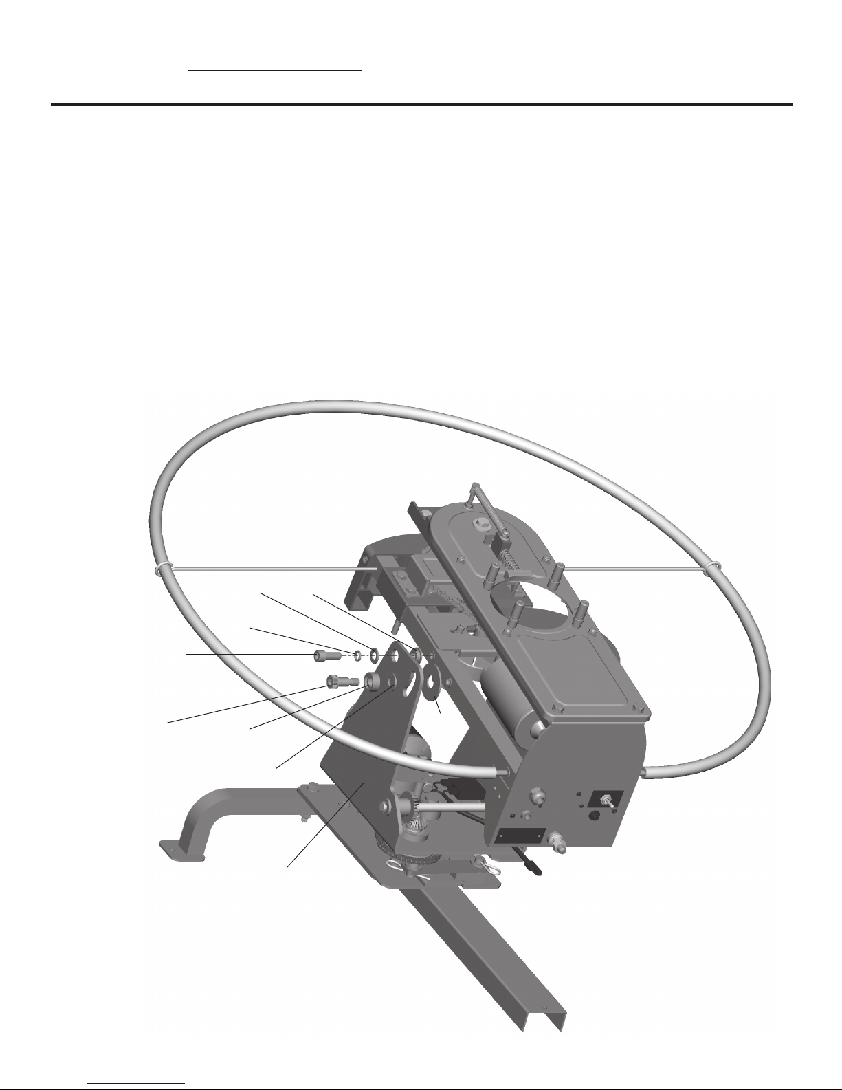
1. For Left and Right motion only:
a. Remove the two hitch pins from the vertical motion linkage as shown.
b. Remove the two washers, linkage, and two bushings. Retain these items for future use.
Note: The throwing arm path indicator has been removed from this image for greater clarity.
17
Page 20

WOBBLE BIRD OPERATION (Alternate Single Axis Motion)
(For Left and Right motion only-continued)
c. Using the provided 8mm hex key, remove M10 Shoulder Bolt (6) with Bolt Cup, Small (10) as shown. Ensure
M12 Washer (13) remains in position between Wobble Bird Sub-Assembly (1) and linkage. Workhorse trap
users, ensure Large Washer (9) between the Workhorse trap chassis and the Wobble Bird Sub-Assembly (1)
stays in position.
10 6
1
Note: The throwing arm path indicator has been removed from this image for greater clarity.
18
Page 21

WOBBLE BIRD OPERATION (Alternate Single Axis Motion)
(For Left and Right motion only-continued)
d. Turn over Bolt Cup, Small (10) and reassemble as shown. Do not tighten bolt completely.
10 6
Note: The throwing arm path indicator has been removed from this image for greater clarity.
19
Page 22

WOBBLE BIRD OPERATION (Alternate Single Axis Motion)
(For Left and Right motion only-continued)
e. On the other side of the trap, using the provided 8mm hex key, remove M10 Shoulder Bolt (6) with Bolt
Cup, Large (11) and M12 Washer (13) as shown. Workhorse trap users, ensure Large Washer (9) between the
Workhorse Trap chassis and the Wobble Bird Sub-Assembly (1) stays in position.
6 11 13
1
Note: The throwing arm path indicator has been removed from this image for greater clarity.
20
Page 23

WOBBLE BIRD OPERATION (Alternate Single Axis Motion)
(For Left and Right motion only-continued)
f. Turn over Bolt Cup, Large (11) and reassemble as shown. Maneuver trap to desired elevation and tighten
both M10 Shoulder Bolts (6) to secure trap in place.
6 11 13
Note: The throwing arm path indicator has been removed from this image for greater clarity.
21
Page 24

WOBBLE BIRD OPERATION (Alternate Single Axis Motion)
1. For Up and Down motion only:
a. Looking at the rear of the trap, remove and retain the two hitch pins as shown.
b. Pull down clevis pin.
c. Rotate horizontal movement linkage as shown and pull down off stud. Retain all components.
22
Page 25

WOBBLE BIRD OPERATION (Alternate Single Axis Motion)
(For Up and Down motion only-continued)
d. Install one end of the horizontal movement linkage onto the stud and capture in place with hitch pin as
shown.
e. Rotate horizontal movement linkage where the clevis pin can be pushed through horizontal movement
linkage and captured in place with hitch pin as shown.
Horizontal Movement Linkage Assembly
23
Page 26

TROUBLESHOOTING
SYMPTOM: UNIT WILL NOT WORK ON A SINGLE AXIS
CORRECTIVE ACTION:
• Ensure battery is connected and fully charged.
• Ensure switch is turned on.
• Ensure circuit breaker has not tripped.
• Ensure Wobble Bird Base is appropriately setup for single axis function. Reference pages 17-23.
SYMPTOM: UNIT WILL NOT WORK ON DUAL AXIS
CORRECTIVE ACTION:
• Ensure battery is connected and fully charged.
• Ensure switch is turned on.
• Ensure circuit breaker has not tripped.
• Ensure Wobble Bird Base is appropriately setup for dual axis function. Your Wobble Bird Base is sent from
the factory in this conguration.
SYMPTOM: MOTOR MOVES BUT WOBBLE BIRD BASE DOES NOT
CORRECTIVE ACTION:
• Ensure desired axis linkage is properly connected.
• Ensure chain is connected and tensioned properly.
SYMPTOM: EXCESSIVE NOISE OR VIBRATIONS
CORRECTIVE ACTION:
• Check all bolts to make sure they are tight.
SYMPTOM: MOTOR WILL NOT RUN
CORRECTIVE ACTION:
• Ensure battery is connected and fully charged.
• Ensure switch for base is turned to ON.
• Ensure circuit breaker has not tripped.
SYMPTOM: CIRCUIT BREAKER KEEPS TRIPPING
CORRECTIVE ACTION:
• Ensure bolt cups are oriented correctly for desired axis function and not binding.
• Ensure all linkage components are in good condition and not binding.
• Ensure the motor, chain, and sprockets are in good condition and not binding.
WARNING: If the above corrective actions do not resolve any issue, do not use the base or the trap.
Contact Champion customer service at (800) 379-1732. Using a malfunctioning trap or base can result in
serious injury or death.
24
Page 27

WARRANTY CERTIFICATE
Congratulations on the purchase of your new CHAMPION WOBBLE BIRD BASE. Your new WOBBLE BIRD BASE is warranted to be free from defects
in material or workmanship for a period of six (6) months from the date of purchase. This warranty is extended only to the original consumer purchaser.
Should you believe that your CHAMPION WOBBLE BIRD BASE is defective in material or workmanship, you should contact the CHAMPION TRAPS
& TARGETS Customer Service Department via phone at 1-800-379-1732. In the event a warranty repair is required, all parts will be provided at no
charge. THIS WARRANTY DOES NOT COVER DEFECTS OR DAMAGE RESULTING FROM: CARELESSNESS, MISUSE, IMPROPER INSTALLATION, MODIFICATION,
OR NORMAL WEAR AND TEAR.
RETAIN THIS WARRANTY CERTIFICATE FOR FUTURE REFERENCE. THE IMPLIED WARRANTIES OF MERCHANTABILITY AND FITNESS FOR A PARTICULAR
PURPOSE ARE LIMITED TO THE DURATION OF THIS LIMITED WARRANTY.
CHAMPION TRAPS AND TARGETS IS NOT LIABLE FOR DAMAGES IN EXCESS OF THE PURCHASE PRICE OF THE PRODUCT AND UNDER NO CIRCUMSTANCES
SHALL CHAMPION TRAPS AND TARGETS BE LIABLE FOR CONSEQUENTIAL OR INCIDENTAL DAMAGES. HOWEVER, SOME STATES DO NOT ALLOW
LIMITATIONS ON INCIDENTAL, OR CONSEQUENTIAL DAMAGES, SO THE ABOVE LIMITATION OR EXCLUSION MAY NOT APPLY TO YOU.
The above warranty provides the sole and exclusive warranty available to the customer in the event of a defect in material or workmanship in the CHAMPION
WOBBLE BIRD BASE. This warranty gives you specic legal rights, and you may also have other rights which vary from State to State.
CHAMPION TRAPS AND TARGETS
9200 Cody
Overland Park, KS 66214
Toll Free: (800) 379-1732
www.championtarget.com
tech.expert@vistaoutdoor.com
25
Page 28

CHAMPION TRAPS AND TARGETS
Website: www.championtarget.com
Email: tech.expert@vistaoutdoor.com
PRINTED IN CHINA MADE IN CHINA 8/20/18
9200 Cody
Overland Park, KS 66214
Toll Free: (800) 379-1732
 Loading...