

Page 1
The New Industrial
Models
(Double Inlet)
AD100, AS100, AD10012, AS10012
AD150, AS150, AD15012, AS15012
AD20012, AS20012, AU20012
(Single Inlet)
SAD100, SAS100, SAD10012, SAS10012
SAD150, SAS150, SAD15012, SAS15012
Circle the model of your cooler and record the
serial number below.
Encierre con un circulo el modelo de su enfriador y
escribe el número de serie abajo.
Serial #
Read And Save These Instructions
Table Of Contents
Safety Instructions .............................................................................2
Operation ............................................................................................2
Installation Instructions ...................................................................2-3
Maintenance Section ..........................................................................3
Troubleshooting .................................................................................4
Warranty .............................................................................................4
Electrical Wiring Diagrams ................................................................5
General Specifi cations ....................................................................... 6
Read Carefully All Of This Manual Before
Installing The Unit.
Lea Con Cuidado T odo Este Manual Antes De Instalar
La Unidad.Número De Serie
Vea el Español en el interior.
Parts List - Wet Section (All models) .............................................6-7
Parts List - Blower Section (AD100B, AD150B, AD200B) ..............8
Parts List - Blower Section (AS100B, AS150B, AS200B) ................9
Parts List - Blower Section (AU200B) ............................................10
Parts List - Blower Section (Single Inlet Coolers) ...........................11
Motor Specifi cations ........................................................................12
Pulley and Belt Kit Specifi cations ...................................................12
Spanish (Instrucciones en Español) ............................................13-16
110526 2-09
Page 2
Safety Rules
1. Read instructions carefully.
2. Disconnect all electrical service that will be used for the unit
before you begin the installation.
3. Electrical hook up should be done by a qualifi ed electrician, so
that all electrical wiring will conform to your local standards.
4. For maximum safety, make sure cooler cabinet is properly
grounded to a suitable ground connection.
5. Cooler must be connected to proper line current, voltage and
cycle, as stamped on cooler motor and pump motor specifi cation
plate.
6. Do not allow pump to tip over and become submerged.
7. Always TURN OFF POWER before performing any mainte-
nance.
Operation
For the best cooling performance, if the pads are dry, pre-wet the pads
by running the pump for a few minutes before starting the blower.
motor mount using these carriage bolts
and the washers and nuts provided
(see Fig. 1). Make sure all bolts are
securely tightened.
• Motor pulley . Install the motor pulley
so that it aligns with the blower pulley
(see Fig. 2) and tighten set screw. See
page 3 for instructions on adjusting pulley.
Blower
Housing
Motor
Pulley
Blower
Pulley
Fig. 2
Electrical Connection
NOTE: Local building code regulations must be observed.
WARNING: Disconnect all electrical services that are used for
this unit before beginning any service to the cooler.
• Electrical supply. Cooler must be supplied with the proper line
current, voltage and frequency, as stamped on blower motor and
pump motor specifi cation plate. See the wiring diagrams on page
4 for typical electrical connections. Note: Connecting improper
voltage to motor will void motor warranty.
These coolers may also be used without water for ventilation purposes.
When outside air is cool (for example, at night) or when humidity is
high the water pump can be turned off.
Important: T o cool effi ciently, you must exhaust the stale or used air
from the building. Open windows or doors or use exhaust fans located
away from the cooler and in the direction you wish to cool the air. The
air will fl ow in the direction of the exhaust openings. A common guide
for the amount of exhaust opening needed is to have at least 2 square
feet of opening per 1000 CFM.
Installation
CAUTION: Make sure that the mounting surface is strong
enough to support the operating weight of the cooler when in use.
(For operating weight, see the general specifi cation table.)
CAUTION: Do not start cooler until installation is complete
and unit has been tested for rigidity.
CAUTION: Make sure all bolts are securely tightened before
starting the cooler.
• Wet sections. The wet sections are bolted to the blower section using
the connector brackets, lift brackets and bolts provided. Match the
colored dots on the wet section to the appropriate dot on the blower
section to insure correct installation.
• Ductwork. See the General Specifi cation table for dimensions of
duct opening. For down discharge units, the duct must go inside
the opening. Size these ducts slightly smaller than the duct opening
in the cooler. The side and up discharge units have a 1 inch fl ange.
Size these ducts larger than the duct opening to fi t over the fl ange of
these units.
Note: Curbs are not provided. The installer is responsible for
providing curbs or other means to support the cooler.
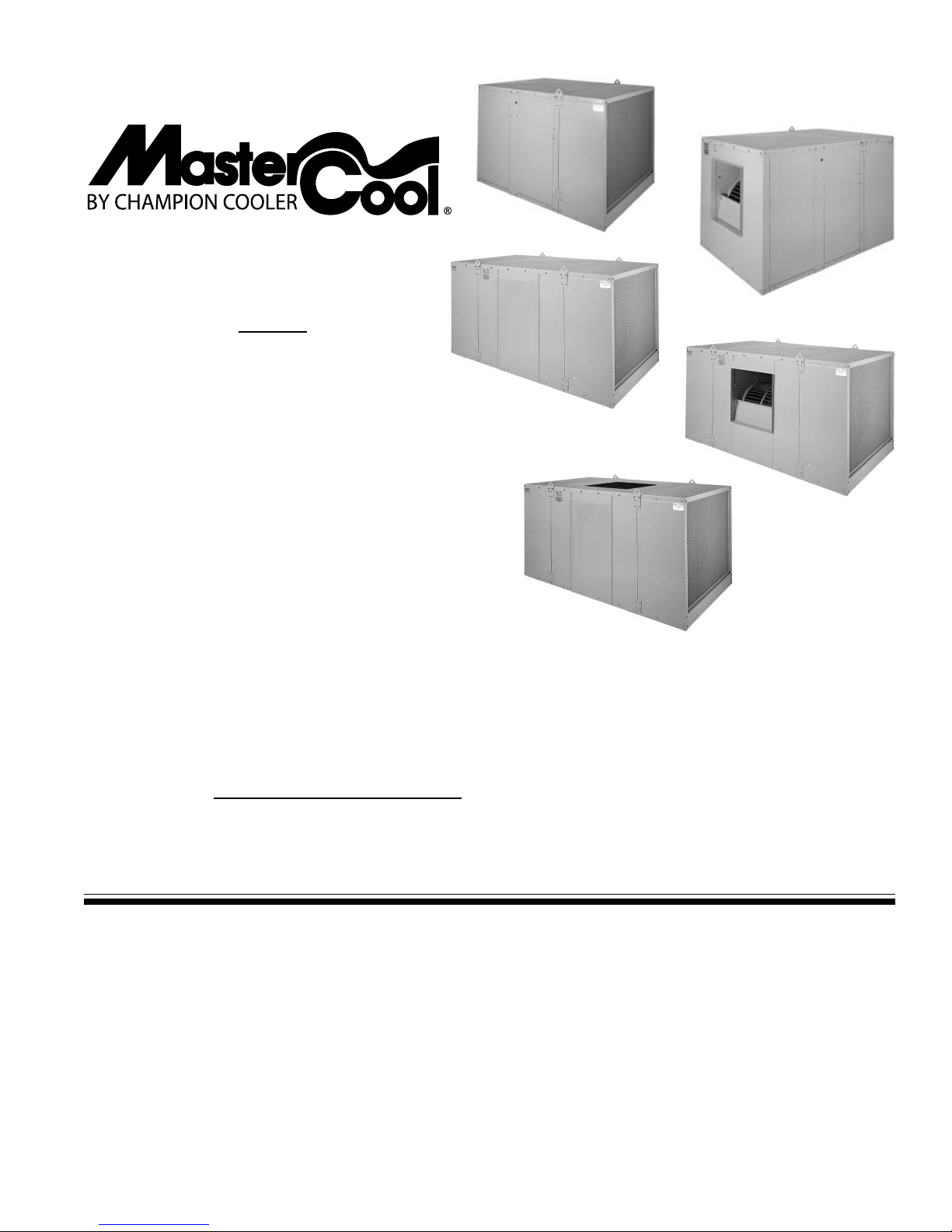
Motor Installation
• Motor mounting. Slide the
heads of the provided carriage
bolts into the slots of the adjustable channels. Slide these
channels sideways in the slotted
holes to align with the holes in
the motor base and to align the
motor shaft with the blower
pulley. Mount the motor to the
Fig. 1
• Wire sizing. The conductor sizes are to be determined by motor
loads and length of run per national and local electrical codes.
• Switches or contactors. Motors require switches or contactors of
proper current capacity and should be sized and installed by a qualifi ed electrician.
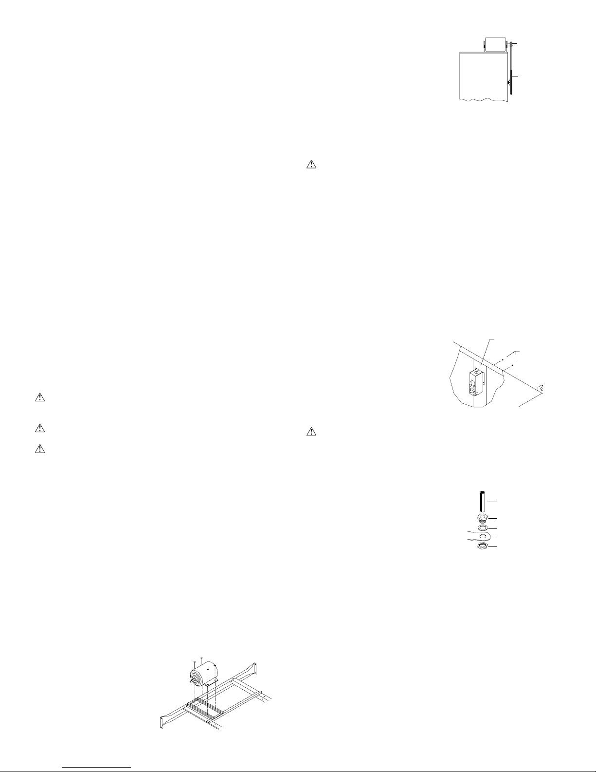
• Wiring. The electrical junction box
is located in the upper inside of the
divider channel. Remove the two
screws and pull the box out from the
channel to access wiring (Fig. 3).
Connect the pump supply wiring to
the pump receptacles (See the pump
wiring diagrams on the next page).
Connect the motor supply wiring
directly to the blower motor.
WARNING: Make sur e that cooler cabinet is properly gr ounded
to a suitable ground connection for maximum safety.
Junction Box
Screws
Fig. 3
Water Connections
• Overfl ow assembly. Remove nut and place nipple through the hole
in the pan, with the rubber washer between the pan and the head of
the drain nipple (Fig. 4). Screw on nut
and draw up tight against bottom of pan.
Insert overfl ow pipe in nipple to retain
water. Overfl ow pipe may be removed
to drain pan when necessary. A garden
hose may be screwed on the drain nipple
to drain water away from your unit.
• Pump. The pump must be secured to prevent it form tipping over.
Secure the pump to the pump mounting bracket (item 16 in parts
drawing). Remove a nut located under the head of the pump, place the
pump bolt though the hole in the mounting bracket, and secure with
the nut that was previously removed. Plug pump into receptacles.
Retain pump cords to internal braces to prevent cords from dropping
into water reservoirs or contacting moving components.
• Supply water . Run a water supply line to the unit. Each wet section
requires a 3/8 inch tube connection to the fl oat valve. The double
inlet units will have two fl oat valves, one for each wet section. Note:
Do not use water supplied from a water softener.
• Float valve. Refer to Fig. 5 to install fl oat. Remove items 1, 2,
3, and 4. Insert fl oat body (5) through hole in splash plate (9) and
back post panel as shown. Install washer (1) and nut (2). Tighten to
Overfl ow Pipe
Nipple
Rubber Washer
Bottom Pan
Nut
Fig. 4
1105262
Page 3
keep fl oat from turning. Place nut
(4) and ferrule (3) on water supply
line. Connect to fl oat fi tting and
tighten until water tight. Turn on
water supply and check for leaks.
8
4
3
2
5
1
Loosen screw (6) and adjust rod
(7) until water level is within 1” of
top of reservoir. T ighten screw (6).
Slide fl oat shield (8) over fl oat body
7
9
6
Fig. 5
(5) until it snaps into place.
• Bleed-Off. Use of the bleed-off kit is recommended to prevent scale
build up by bleeding off small amounts of circulating water during
operation. Do not add any type of water treatment chemicals to the
water since they may damage the evaporative media.
Pulley And Belt Adjustments
• Pulley adjustment. With an ammeter, check the motor amperage.
Adjust the pulley until the amperage draw on the motor is just below
that specifi ed on the motor nameplate. T o
adjust the pulley, loosen the adjustment
set screw and rotate the sheave. Tighten
the set screw so that it is over a fl at area,
otherwise thread damage will occur. To
Decrease
Amperage
increase amperage draw, increase pulley
diameter. To decrease amperage draw,
decrease pulley diameter (see Fig. 6).
Fig. 6
Recheck belt alignment.
CAUTION: Always check the amperage of the motor after adjusting pulley to be certain it does not exceed the amperage stamped
on the motor specifi cation plate. Improper pulley adjustment will
overload and burn out the motor.
• Belt tension. Loosen the motor mount
3 Lb.
3/4 Inches
bolts and slide the motor back until the
belt is properly tensioned. A 3 lb. force
should defl ect the belt 3/4 inches (see
Fig. 7). Retighten motor mount bolts.
Fig. 7
Do not adjust pulley to tighten belt.
Maintenance
WARNING: Befor e doing any maintenance be sure to disconnect
from power source. This is for your safety.
Spring Start-Up
• Belt tension. Check belt tension and readjust if needed.
• Grease bearings. The blower bearings in this unit should be greased
once a year with a good grade of ball bearing grease.
• Cleaning pads. A clean pad is more absorbent, effi cient and will give
more cool air. Annually, or when required, using a garden hose with
nozzle, back wash to clean out the openings, then clean off the inlet
face any scale or other obstruction to the passages. Slight scraping
may be required to remove hardened scale.
• Pad replacement. The pads should be replaced after 5 years or if
necessary. To change pads, remove top access panel, remove grill,
and disconnect water delivery tube. Remove water distributor holder
and lift out media sections. Replace with the same type media. You
can purchase them from your dealer.
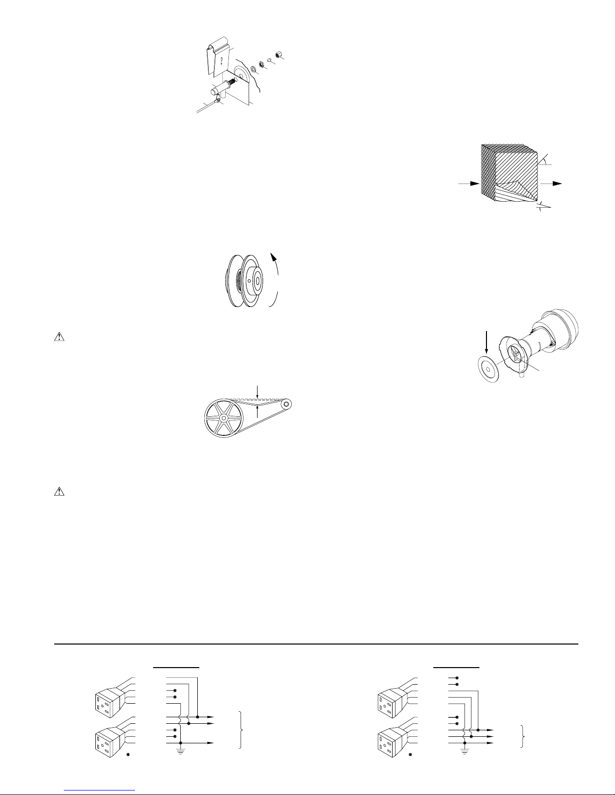
IMPORTANT: In order to get the best performance from your cool-
ing pads, they must be installed properly. If you have purchased a pad
with two equal angles, the following instructions can be disregarded.
Pads must always be installed with the steeper fl ute angle sloping
down towards the air entering side (Fig. 8). The reason is simple. The steeper
angle puts more water on
the hot, dry, dirty side of
Entering
Air
45°
Leaving Air
the pad where it is needed
most. It also counteracts
the tendency of the air to
push the water toward the
Fig. 8
15°
back of the pad.
• Cleaning pump. Cleaning the pump is necessary once a year at start-
up. For your safety, disconnect from power source and unplug pump.
Remove the pump from the mount bracket. Remove the base of the
pump (Fig. 9). Clean the pump and turn the impeller to ensure free
operation. Remove the pump spout and check for any blockage. After
cleaning, reinstall the base onto
the pump. Reattach the pump to
the mount in the cooler to ensure
Remove
Base
that the pump will not overturn.
Do not forget to replace the spout
and water delivery tube onto the
pump outlet. The pump has automatic reset thermal protection.
Pump will operate normal again
Impeller
Fig. 9
after obstruction is cleared.
• Bleed off. Check bleed-off valve to be sure it is not clogged.
Winter Shut Down
• Drain water . Always drain all of the water out of the cooler and water
supply line when not in use for prolonged periods, and particularly at
the end of the season. Keep the water line disconnected from both
the unit and water supply so that it does not freeze.
• Disconnect from power supply when not in use for extended
periods of time.
• Cover unit. To protect the life of the fi nish, a cover for the unit is
suggested in extended periods of non use.
By following the operating, installation, and maintenance suggestions
as outlined, you can get many years of effi cient and satisfactory service
from your cooler. In the event additional information is desired, your
dealer will be more than glad to assist you in every possible way.
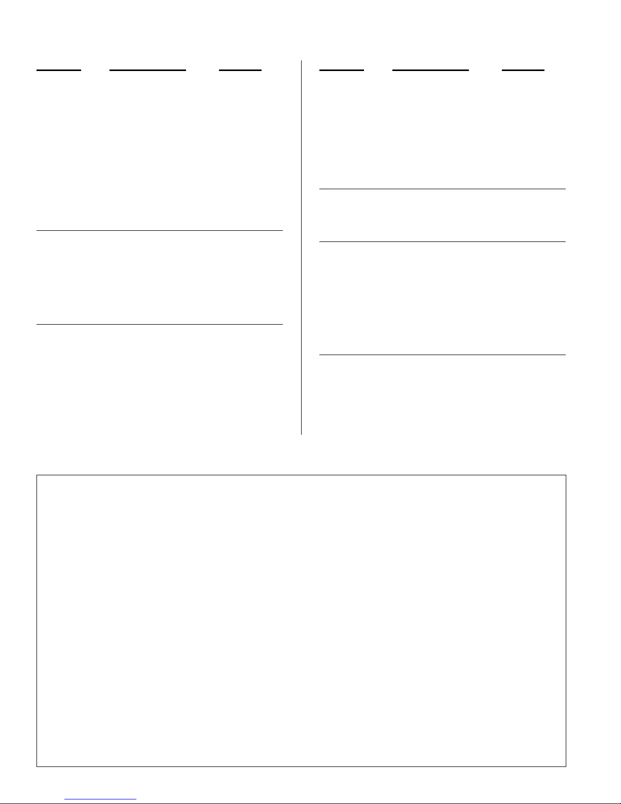
120 Volts 240 Volts
Blue/Black
White
Brown
Orange
Green
Blue/Black
White
Brown
Orange
Green
= Wire Nut
110526 3
Pump
Com.
Ground
Pump Wiring Diagrams
To
Switch
Blue/Black
White
Brown
Orange
Green
Blue/Black
White
Brown
Orange
Green
=WireNut
Pump
Com.
Ground
To
Switch
Page 4
Troubleshooting Guide
Problem Possible Cause Remedy Problem Possible Cause Remedy
Failure to
start or no air
delivery
Inadequate
air delivery
with cooler
running
Musty or
unpleasant
odor
1. No electrical power
to unit
• Fuse blown
• Circuit breaker tripped
2. Belt too loose or tight
3. Motor overheated
• Belt too tight
• Blower bearings dry
• Motor bearings dry
• Motor pulley diameter
too large
4. Motor locked
1. Insuffi cient air exhaust
2. Belt too loose
3. Pads plugged
4. Insuffi cient water fl ow
over pads
1. Stale or stagnate water
in cooler
2. Pads not wetting
properly
• Dist. tube holes
clogged
• Pump not working
properly
• Insuffi cient water fl ow
over pads
1. Check power
• Replace fuse
• Reset breaker
2. Adjust belt tension
3. Determine cause of
overheating
• Adjust belt tension
• Grease blower bear-
ings
• Oil motor bearings
• Adjust pulley to cor-
rect diameter
4. Replace motor
1. Open windows or
doors to increase air
fl ow
2. Adjust belt tension or
replace if needed
3. Clean pads
4. Clean distribution
system
1. Drain pan and clean
pads
2. Check water distribution system
• Clean
• Replace or clean
pump (Unplug)
• Clean water distribu-
tion system
Motor
cycles on
and off
Noisy
Inadequate
cooling
Excessive
humidity in
house
1. Low voltage
2. Excessive belt tension
3. Blower shaft tight or
locked
4. Bearings dry
5. Motor pulley diameter
too large causing motor
overload
6. Faulty motor
1. Bearings dry
2. Wheel rubbing blower
housing
3. Loose parts
1. Inadequate exhaust in
house
2. Pads not wet
• Pads plugged
• Dist. tube holes
clogged
• Pump not working
properly
1. Inadequate exhaust
1. Check voltage
2. Adjust belt tension
3. Grease or replace
bearings (Disconnect
unit)
4. Grease bearings
5. Adjust pulley so full
load ampere rating of
motor is not exceeded
6. Replace motor
1. Grease bearings
2. Inspect and realign
(Disconnect unit)
3. Tighten loose parts
1. Open windows or
doors to increase air
fl ow
2. Check water distribution system
• Clean pads
• Clean
• Replace or clean
pump (Unplug)
1. Open doors or win-
dows
Register your product online at www.championcooler.com/eac/onlineregistration-eac.htm
Limited W arranty
This warranty is extended to the original purchaser of an evaporative cooler installed and used under normal conditions. It does not cover damages incurred through accident, neglect, or abuse by the owner. We do not authorize any person or representative to assume for us any other or different liability
in connection with this product.
Terms And Conditions Of The Warranty
Lifetime Limited Coverage on water reservoir against any leakage due to defects in material. From date of purchase, if any original component part fails
due to defect in material or factory workmanship only, we will provide the replacement part as follows:
One year on the cabinet components.
Two years on the evaporative media.
Exclusions From The Warranty
We are not responsible for any incidental or consequential damage resulting from any malfunction.
We are not responsible for any damage received from the use of water softeners, chemicals, de-scale material, plastic wrap, or if a motor of a higher
horsepower than what is shown on the serial plate is used in the unit.
We are not responsible for the cost of service calls to diagnose cause of trouble, or labor charge to repair and/or replace parts.
How To Obtain Service Under This Warranty
Contact the Dealer where you purchased the evaporative cooler. If for any reason you are not satisfi ed with the response from the dealer, contact the
Customer Service Department: 5800 Murray Street, Little Rock, Arkansas 72209. 1-800-643-8341. E-mail: info@championcooler.com, Web: www.
championcooler.com.
This limited warranty applies to original purchaser only.
1105264
Page 5

Typical Electrical Wiring Diagrams
Disconnect Switch At Cooler
See Notes 1 & 2
Equipment
Ground
Blower Motor
208, 240, or 480 Volt, 3 Phase Blower & 120 Volt 1 Phase Pump & Control Electric Supply
Motor Starter With
Overload Protection
Sized To Match Motor
Full Load Current
See Note 1
Disconnect Switch
At Cooler
See Notes 1 & 2
120 Volt, 1 Phase Electric Supply
Control Contacts
L
H
P
N
Fuses
See Note 1
Cooler Cabinet
See Note 3
See Note 4
• 115 Volt single phase blower motor.
• 120 Volt pump motor.
• Diagram shown for two speed motor.
Low speed circuit drawn with dashed
Pump Motor
T3
T2
T1
Gnd
Equipment
Ground
lines is not required for single speed.
Control Contacts
See Note 4
Blower Motor
L1
120 Volts
N
Power Supply
N
Gnd
Fuses
See Note 1
1 Phase
• Three phase single speed blower motor
• Three pole motor starter with overload
protection
• 120V single phase control and pump shown.
If 240V control and pump are to be used, then
GndGnd
Main Disconnect
See Note 1
H
P
Disconnect Switch At Cooler
See Note 1&2
Cooler Cabinet
See Note 3
Pump Motor
both legs of power supply must be fused.
Equipment
Ground
Blower Motor
240 Volt, 1 Phase Electric Supply
Disconnect Switch At Cooler
See Notes 1 & 2
L
H
120V
Pump Motor
Gnd
L1
L2
L3
Main Disconnects
See Note 1
L1
N
Gnd
P
L2
Gnd
Transformer
Cooler Cabinet
See Note 3
208, 240, or 480V
3 Phase
Power Supply
120V
1 Phase
Power Supply
Control Contacts
See Note 1
L1
208 or 240V
Fuses
See Note 1
L2
Gnd
Main Disconnect
See Note 1
1 Phase
Power Supply
• 230 Volt single phase blower motor.
• 120V pump motor shown. Transformer may be omitted when a 240V
pump is used with a 240V supply
• Diagram shown for two speed motor.
Low speed circuit drawn with dashed
lines is not required for single speed.
Typical Control Contacts
Function and Connection
L - Low Fan
P - Pump
H - Hi Fan
L1 - Supply Power
Function Connection
Off None
Pump Only L1-P
Hi-Cool L1-H
* Low-Cool L1-L & L1-P
Hi-Fan L1-H
* Low-Fan L1-L
* Omit for single speed blower motor
208, 240, or 480 Volt, 3 Phase Blower Electric Supply With Transformer For Pump & Control
Motor Starter With
Overload Protection
Sized To Match Motor
Full Load Current
See Note 1
Disconnect Switch At Cooler
See Notes 1 & 2
T3
T2
T1
Gnd
Equipment
Ground
Control Contacts
See Note 4
Blower Motor
H
P
Disconnect Switch At Cooler
See Notes 1 & 2
Cooler Cabinet
See Note 3
Pump Motor
120
V
Fuses
See Note 1
Transformer
See Note 1
• Three phase single speed blower motor.
• Three pole motor starter with overload protection.
• 120V single phase pump powered by a transformer.
Transformer may be omitted when 240V control &
pump are used with a 240V supply.
Gnd
L1
L2
L3
208, 240 or 480V
Main Disconnect
See Note 1
3 Phase
Power Supply
WARNING: Electrical hookup should be performed by a qualifi ed electrician. All electrical wiring must conform to national and local
standards.
NOTE 1. All switches, motor starters, transformers, fuses, junction boxes, receptacles, receptacle boxes, cover plates, and conductors shall be supplied by the
NOTE 2. The national electric code requires a disconnect switch located at equipment if the main disconnect at equipment controller is not visible from the equip-
NOTE 3. A receptacle for a NEMA 5-15P plug is required for 120V recirculating pump and a receptacle for a NEMA 6-15P plug for 230V pump.
NOTE 4. The control contacts may be part of a switch, thermostat or other control device.
installer.
ment. If more than one disconnect is used they must be mounted adjacent to one another.
110526 5
Page 6
General Specifi cations / Especifi caciones Generales
Model No.
Mod el o
AD100 517 717 44 81 3/4 45 21 3/4 21 3/4
AS100 511 711 44 81 3/4 45 21 3/4 21 3/4
AD10012 571 812 44 89 3/4 45 21 3/4 21 3/4
AS10012 565 806 44 89 3/4 45 21 3/4 21 3/4
AD150 648 863 54 85 48 1/4 26 7/8 26 7/8
AS150 640 856 54 85 48 1/4 26 7/8 26 7/8
AD15012 714 974 54 93 48 1/4 26 7/8 26 7/8
AS15012 706 967 54 93 48 1/4 26 7/8 26 7/8
AD20012 928 1208 59 1/4 105 1/4 60 1/4 31 3/4 31 3/4
AS20012 914 1194 59 1/4 105 1/4 60 1/4 31 3/4 31 3/4
AU20012 914 1194 59 1/4 105 1/4 60 1/4 31 3/4 31 3/4
SAD100 417 517 44 63 3/8 45 21 3/4 21 3/4
SAS100 411 511 44 63 3/8 45 21 3/4 21 3/4
SAD10012 444 565 44 67 3/8 45 21 3/4 21 3/4
SAS10012 438 559 44 67 3/8 45 21 3/4 21 3/4
SAD150 533 641 54 66 5/8 48 1/4 26 7/8 26 7/8
SAS150 525 633 54 66 5/8 48 1/4 26 7/8 26 7/8
SAD15012 566 696 54 70 5/8 48 1/4 26 7/8 26 7/8
SAS15012 558 688 54 70 5/8 48 1/4 26 7/8 26 7/8
*Does no t include moto r weight. / No incluye el peso del motor.
*Weight (lbs.)
Peso (libras)
*Dry
Seco
*Operating
Lleno
Height
Altura
Cabine t D ime ns ions (in.)
Dimensiones De La Caja (pulgadas)
Width
Anchura
Profundidad
Depth
Duct Opening (in.)
Abertura De Ducto (pulgadas)
Width
Anchura
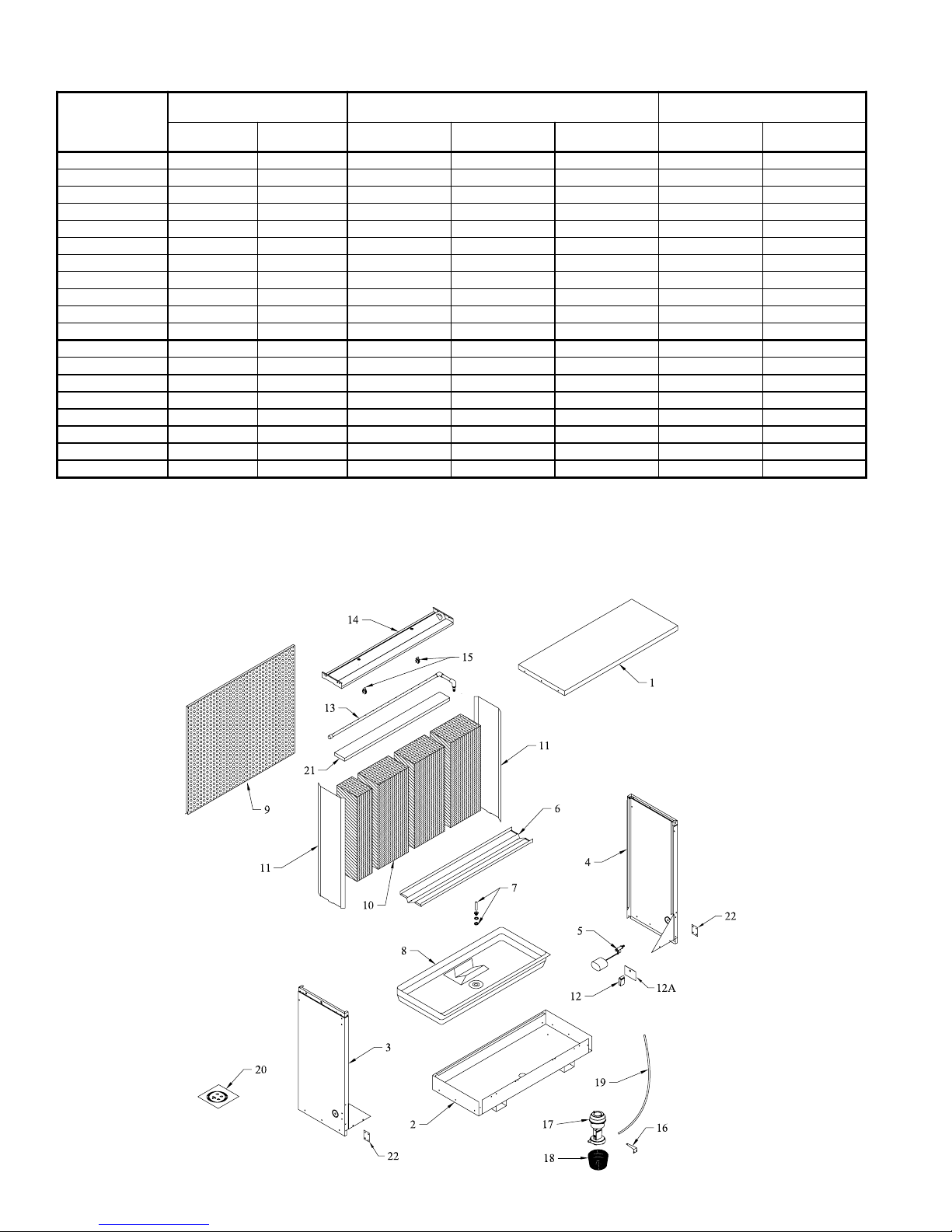
Replacement Parts / Piezas De Repuesto
Height
Altura
SAS/SAD100W, SAS/SAD10012W, SAS/SAD150W, SAS/SAD15012W
AS/AD100W , AS/AD10012W, AS/AD150W, AS/AD15012W , AS/AD/AU20012W
1105266
Page 7

Replacement Parts / Piezas De Repuesto
When ordering parts, please be sure to furnish the following information on all orders. Failure to do so may delay your order. /
Al pedir piezas, incluya toda la información siguiente con su pedido. El no proporcionar toda esta información resultará en una demora.
1. Cooler serial number / Número de serie de la unidad.
2. Description and part number / Descripción y número de pieza.
3. Cooler size / Tamaño de la unidad.
4. Date of purchase / Fecha de compra.
No.
N° Description / Descripción 100W 150W
1. Top Access Panel / Panel Superior De Acceso -------------------------------------------------------------------------218115-002 218116-007
2. Bottom, Cabinet / Base De La Caja --------------------------------------------------------------------------------------318115-004 318116-009
3. Side Panel, Right / Panel Del Lado, Derecho---------------------------------------------------------------------------318115-008 318116-013
4. Side Panel, Left / Panel Del Lado, Izquierdo ---------------------------------------------------------------------------318115-021 318116-039
5. Float Valve / Flotador ------------------------------------------------------------------------------------------------------FL-3/8 FL-3/8
6. Support, Media / Soporte Para El Medio Evaporativo ----------------------------------------------------------------218115-015 218116-020
7. Over Flow Assembly / Montaje De Desagüe ---------------------------------------------------------------------------3OA-2 3OA-2
8. Water Reservoir / Bandeja Acumuladora De Agua -------------------------------------------------------------------- 281028 281029
9. Perforated Panel / Parrilla Perforada -----------------------------------------------------------------------------------220126-002 220126-003
10. Evaporative Media / Medio Evaporativo --------------------------------------------------------------------------------110107 110106
11. Media Shield / Pantalla Protectora Para El Medio Evaporativo ----------------------------------------------------281026-003 281026-004
12. Float Shield / Salpicadero Del Flotador ---------------------------------------------------------------------------------281006 281006
12a. Float Splash Plate / Placa Para Salpicaduras --------------------------------------------------------------------------281026-013 281026-013
13. Water Distributor Assembly / Sistema Del Distribuidor De Agua ---------------------------------------------------3D-21R 3D-20R
14. Water Distributor Housing / Caja Del Distribuidor De Agua --------------------------------------------------------322130-059 322140-041
15. Water Distributor Tube Clamp / Abrazadera De Tubo Del Distribuidor De Agua --------------------------------110591 110591
16. Pump Mount / Soporte De La Bomba ------------------------------------------------------------------------------------218122-004 218122-004
17. Pump / Bomba ---------------------------------------------------------------------------------------------------------------* *
18. Pump Screen / Malla Para La Bomba -----------------------------------------------------------------------------------281001-001 281001-001
19. Tube, Water Delivery / Tubo De Agua -----------------------------------------------------------------------------------110717 110717
20. Bleed-Off Kit / Equipo De La Válvula De Desahogo -----------------------------------------------------------------310587 310587
21. Hobbs Polyester Pad / Filtro De Poliester ------------------------------------------------------------------------------110119-2 110119-3
22. Connect Bracket / Abrazadera Del Conectar ---------------------------------------------------------------------------214120-001 214120-001
No.
N° Description / Descripción 10012W 15012W 20012W
1. Top Access Panel / Panel Superior De Acceso --------------------------------------------------218115-016 218116-021 218116-035
2. Bottom, Cabinet / Base De La Caja ---------------------------------------------------------------318115-017 318116-022 318116-036
3. Side Panel, Right / Panel Del Lado, Derecho----------------------------------------------------318115-018 318116-023 318116-032
4. Side Panel, Left / Panel Del Lado, Izquierdo ----------------------------------------------------318115-022 318116-040 318116-033
5. Float Valve / Flotador -------------------------------------------------------------------------------FL-3/8 FL-3/8 FL-3/8
6. Support, Media / Soporte Para El Medio Evaporativo -----------------------------------------218115-019 218116-024 218116-034
7. Over Flow Assembly / Montaje De Desagüe ----------------------------------------------------3OA-2 3OA-2 3OA-2
8. Water Reservoir / Bandeja Acumuladora De Agua ---------------------------------------------281034 281027 281037
9. Perforated Panel / Parrilla Perforada ------------------------------------------------------------220126-002 220126-003 220126-004
10. Evaporative Media / Medio Evaporativo ---------------------------------------------------------110111 110110 1101 12
11. Media Shield / Pantalla Protectora Para El Medio Evaporativo -----------------------------281026-006 281026-005 281026-008
12. Float Shield / Salpicadero Del Flotador ----------------------------------------------------------281006 281006 281006
12a. Float Splash Plate / Placa Para Salpicaduras ---------------------------------------------------281026-013 281026-013 281026-013
13. Water Distributor Assembly / Sistema Del Distribuidor De Agua ----------------------------3D-25R 3D-24R 3D-28R
14. Water Distributor Housing / Caja Del Distribuidor De Agua ---------------------------------322130-058 322140-042 322140-040
15. Water Distributor Tube Clamp / Abrazadera De Tubo Del Distribuidor De Agua
16. Pump Mount / Soporte De La Bomba -------------------------------------------------------------218122-004 218122-004 218122-004
17. Pump / Bomba ----------------------------------------------------------------------------------------* * *
18. Pump Screen / Malla Para La Bomba ------------------------------------------------------------281001-001 281001-001 281001-001
19. Tube, Water Delivery / Tubo De Agua ------------------------------------------------------------110717 110717 110717
20. Bleed-Off Kit / Equipo De La Válvula De Desahogo ------------------------------------------310587 310587 310587
21. Hobbs Polyester Pad / Filtro De Poliester -------------------------------------------------------110119-2 110119-3 110119-4
22. Connect Bracket / Abrazadera Del Conectar ----------------------------------------------------214120-001 214120-001 214120-001
* 115V - 110467
230V - 110468
-----------
110591 110591 110591
110526 7
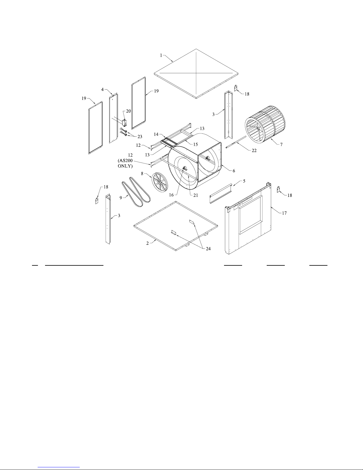
Page 8

Replacement Parts / Piezas De Repuesto
AD100B, AD150B, AD200B
No.
N° Description / Descripción AD100B AD150B AD200B
1. Top, Cabinet / Tapa De La Caja ------------------------------------------------------------- 218115-003 218116-008 216117-003
2. Bottom, Cabinet / Base De La Caja ---------------------------------------------------------- 318115-005 318116-010 318117-007
3. Corner Post / Poste De Esquina --------------------------------------------------------------318115-013 318116-018 318117-012
4. Divider Channel / Canal Divisora ------------------------------------------------------------ 218115-014 218116-019 218117-013
5. Cut-Off Plate / Placa Limitadora -------------------------------------------------------------320102-002 318112-004 318112-003
6. Blower Housing / Caja De La Rueda -------------------------------------------------------- 322115-002 320116-001 320117-001
7. Blower Wheel / Rueda ------------------------------------------------------------------------- 110749 110750 110751
8. Pulley, Blower Wheel / Polea De La Rueda ------------------------------------------------110297 110298 110298
9. Drive Belt / Correa ----------------------------------------------------------------------------- † † †
10. Motor / Motor ----------------------------------------------------------------------------------- * * *
11. Pulley, Motor / Polea Del Motor ------------------------------------------------------------- † † †
12. Channel Retainer / Soporte De Canal -------------------------------------------------------- 214007-001 214007-006 214109-001
13. Motor Mount Support / Soporte Para La Montura Del Motor --------------------------- 214118-003 214116-008 206102-001
14. Motor Mount Adjustable Channel / Montura Ajustable Del Motor --------------------- 214112-002 214112-004 214112-004
15. Motor Mount Crossbrace / Travesaño De La Montura Del Motor ---------------------- 214001-005 214001-009 214001-007
16. Bearings, Blower Wheel Shaft / Cojinetes Del Eje De La Rueda ------------------------ 110355 110356 110356
17. Front Panel / Panel Del Frente----------------------------------------------------------------318115-024 318116-048 318117-011
18. Lift Bracket / Soporte De Levantamiento --------------------------------------------------- 212101-001 212101-001 212101-001
19. Inspection Panel / Panel De Inspección ----------------------------------------------------- 220115-003 220116-004 220116-007
20. Electrical Junction Box / Caja De Empalme ------------------------------------------------322009-003 322009-003 322009-003
21. Bearing Mount Support / Soporte Para Los Cojinetes ------------------------------------ 206100-002 206100-004 206100-005
22. Shaft, Blower Wheel / Eje De La Rueda ---------------------------------------------------- 110157 110158 110159
23. Receptacle, Pump / Toma De Corriente De La Bomba ------------------------------------ 110361 110361 110361
* See motor specifi cation table. / Vea la tabla de especifi caciones del motor.
† See pulley and belt table. / Vea la tabla de especifi caciones del polea y correa.
NOTE: Standard hardware items may be purchased from your local hardware store.
NOTA: Artículos de uso corriente pueden comprarse en la ferretería de su localidad.
1105268
Page 9
Replacement Parts / Piezas De Repuesto
AS100B, AS150B, AS200B
No.
N° Description / Descripción AS100B AS150B AS200B
1. Top, Cabinet / Tapa De La Caja ------------------------------------------------------------- 218115-003 218116-008 216117-003
2. Bottom, Cabinet / Base De La Caja ---------------------------------------------------------- 318115-020 318116-026 316117-004
3. Corner Post / Poste De Esquina -------------------------------------------------------------- 318115-013 318116-018 318117-018
4. Divider Channel / Canal Divisora ------------------------------------------------------------ 218115-014 218116-019 218117-013
5. Cut-Off Plate / Placa Limitadora -------------------------------------------------------------320102-002 318112-004 318112-003
6. Blower Housing / Caja De La Rueda -------------------------------------------------------- 322115-002 320116-001 320117-001
7. Blower Wheel / Rueda ------------------------------------------------------------------------- 110749 110750 110751
8. Pulley, Blower Wheel / Polea De La Rueda ------------------------------------------------110297 110298 110298
9. Drive Belt / Correa ----------------------------------------------------------------------------- † † †
10. Motor / Motor ----------------------------------------------------------------------------------- * * *
11. Pulley, Motor / Polea Del Motor ------------------------------------------------------------- † † †
12. Channel Retainer / Soporte De Canal -------------------------------------------------------- 214007-001 214007-006 214109-001
13. Motor Mount Support / Soporte Para La Montura Del Motor --------------------------- 214115-004 214116-009 206102-002
14. Motor Mount Adjustable Channel / Montura Ajustable Del Motor --------------------- 214112-002 214112-004 214112-004
15. Motor Mount Crossbrace / Travesaño De La Montura Del Motor ---------------------- 214001-005 214001-009 214001-007
16. Bearings, Blower Wheel Shaft / Cojinetes Del Eje De La Rueda ------------------------ 110355 110356 110356
17. Front Panel / Panel Del Frente----------------------------------------------------------------318115-009 318116-014 318117-010
18. Lift Bracket / Soporte De Levantamiento --------------------------------------------------- 212101-001 212101-001 212101-001
19. Inspection Panel / Panel De Inspección ----------------------------------------------------- 220115-003 220116-004 220116-007
20. Electrical Junction Box / Caja De Empalme ------------------------------------------------322009-003 322009-003 322009-003
21. Bearing Mount Support / Soporte Para Los Cojinetes ------------------------------------ 206100-001 206100-003 206100-006
22. Shaft, Blower Wheel / Eje De La Rueda ---------------------------------------------------- 110157 110158 110159
23. Receptacle, Pump / Toma De Corriente De La Bomba ------------------------------------ 110361 110361 110361
24. Blower Support Bracket / Soporte De La Caja De La Rueda ---------------------------- 218122-005 218122-005 218122-005
* See motor specifi cation table. / Vea la tabla de especifi caciones del motor.
† See pulley and belt table. / Vea la tabla de especifi caciones del polea y correa.
NOTE: Standard hardware items may be purchased from your local hardware store.
NOTA: Artículos de uso corriente pueden comprarse en la ferretería de su localidad.
110526 9
Page 10

Replacement Parts / Piezas De Repuesto
AU200B
No.
N° Description / Descripción AU200B
1. Top, Cabinet / Tapa De La Caja ...........................................................................................................................316117-007
2. Bottom, Cabinet / Base De La Caja .......................................................................................................................316117-004
3. Corner Post / Poste De Esquina .............................................................................................................................318117-020
4. Divider Channel / Canal Divisora .........................................................................................................................218117-013
5. Cut-Off Plate / Placa Limitadora...........................................................................................................................318112-003
6. Blower Housing / Caja De La Rueda ....................................................................................................................320117-001
7. Blower Wheel / Rueda ...........................................................................................................................................110751
8. Pulley, Blower Wheel / Polea De La Rueda ..........................................................................................................110298
9. Drive Belt / Correa ................................................................................................................................................†
10. Motor / Motor ........................................................................................................................................................*
11. Pulley, Motor / Polea Del Motor ...........................................................................................................................†
12. Channel Retainer / Soporte De Canal ....................................................................................................................214109-002
13. Motor Mount Support / Soporte Para La Montura Del Motor ..............................................................................206102-003
14. Motor Mount Adjustable Channel / Montura Ajustable Del Motor......................................................................214112-004
15. Motor Mount Crossbrace / Travesaño De La Montura Del Motor .......................................................................214001-007
16. Bearings, Blower Wheel Shaft / Cojinetes Del Eje De La Rueda .........................................................................110356
17. Front Panel / Panel Del Frente ..............................................................................................................................318117-022
18. Lift Bracket / Soporte De Levantamiento ..............................................................................................................212101-001
19. Inspection Panel / Panel De Inspección .................................................................................................................220116-007
20. Electrical Junction Box / Caja De Empalme .........................................................................................................322009-003
21. Bearing Mount Support / Soporte Para Los Cojinetes ..........................................................................................206100-005
22. Shaft, Blower Wheel / Eje De La Rueda ...............................................................................................................110159
23. Receptacle, Pump / Toma De Corriente De La Bomba .........................................................................................110361
24. Blower Support Bracket / Soporte De La Caja De La Rueda ...............................................................................218122-005
* See motor specifi cation table. / Vea la tabla de especifi caciones del motor.
† See pulley and belt table. / Vea la tabla de especifi caciones del polea y correa.
NOTE: Standard hardware items may be purchased from your local hardware store.
NOTA: Artículos de uso corriente pueden comprarse en la ferretería de su localidad.
11052610
Page 11

Replacement Parts / Piezas De Repuesto
SAD100B, SAD150B SAS100B,SAS150B
No.
N° Description / Descripción SAD100B SAS100B SAD150B SAS150B
1. Top, Cabinet / Tapa De La Caja ................................................................. 218115-003 218115-003 218116-008 218116-008
2. Bottom, Cabinet / Base De La Caja ............................................................. 318115-005 318115-020 318116-010 318116-026
3. Corner Post / Poste De Esquina ................................................................... 318115-013 318115-013 318116-018 318116-018
4. Divider Channel / Canal Divisora ............................................................... 218115-014 218115-014 218116-019 218116-019
5. Cut-Off Plate / Placa Limitadora................................................................. 320102-002 320102-002 318112-004 318112-004
6. Blower Housing / Caja De La Rueda .......................................................... 322115-002 322115-002 320116-001 320116-001
7. Blower Wheel / Rueda ................................................................................. 110749 110749 110750 110750
8. Pulley, Blower Wheel / Polea De La Rueda ................................................ 110297-1 110297-1 110298-1 110298-1
9. Drive Belt / Correa ...................................................................................... † † † †
10. Motor / Motor .............................................................................................. * * * *
11. Pulley, Motor / Polea Del Motor ................................................................. † † † †
12. Channel Retainer / Soporte De Canal .......................................................... 214007-001 214007-001 214007-006 214007-006
13. Motor Mount Support / Soporte Para La Montura Del Motor .................... 214118-003 214115-004 214116-008 214116-009
14. Motor Mount Adjustable Channel / Montura Ajustable Del Motor............ 214112-002 214112-002 214112-004 214112-004
15. Motor Mount Crossbrace / Travesaño De La Montura Del Motor ............. 214001-005 214001-005 214001-009 214001-006
16. Bearings, Blower Wheel Shaft / Cojinetes Del Eje De La Rueda ............... 110355 110355 110356 110356
17. Front Panel / Panel Del Frente .................................................................... 318115-024 318115-009 318116-048 318116-014
18. Lift Bracket / Soporte De Levantamiento .................................................... 212101-001 212101-001 212101-001 212101-001
19. Inspection Panel / Panel De Inspección .......................................................220115-003 220115-003 220116-004 220116-004
20. Electrical Junction Box / Caja De Empalme ............................................... 322009-002 322009-002 322009-002 322009-002
21. Bearing Mount Support / Soporte Para Los Cojinetes ................................ 206100-002 206100-001 206100-004 206100-003
22. Shaft, Blower Wheel / Eje De La Rueda ..................................................... 110157 110157 110158 110158
23. Receptacle, Pump / Toma De Corriente De La Bomba ............................... 110361 110361 110361 110361
24. Blower Support Bracket / Soporte De La Caja De La Rueda ..................... - 218122-005 - 218122-005
* See motor specifi cation table. / Vea la tabla de especifi caciones del motor.
† See pulley and belt table. / Vea la tabla de especifi caciones del polea y correa.
NOTE: Standard hardware items may be purchased from your local hardware store.
NOTA: Artículos de uso corriente pueden comprarse en la ferretería de su localidad.
110526 11
Page 12

Motor Specifi cations / Especifi caciones Del Motor
HP
C.V.
3/4
1
1-1/2
2
3 +110465-9 3 1 230/460 9.6/4.8 83 1-1/8
5 +110466-9 3 1 230/460 15.2/7.6 87 1-1/8
7-1/2 +110470-9 3 1 230/460 22/11 121 1-3/8
10 +110482-9 3 1 230/460 28/14 138 1-3/8
+ EPACT Motors / Motores de buen rendimiento.
* Amperage shown is from National Electrical Code. Use amperage shown on motor nameplate to determine motor protector.
El amperaje listado es del código eléctrico nacional. Utilice el amperaje indicado en la placa del motor para determinar el tamaño del protector del motor.
M oto r Pa rt N o .
N° Del Motor
110455
110461
110457
110458
+110462-9
110459-1
+110463-9
110460-1
+110464-9
Phase
Fase
1
3
1
1
3
1
3
1
3
Speed
Velocidad
1
1
1
2
1
1
1
1
1
Vo lt s
Voltios
115/208-230
208-230/460
115/230
230
208-230/460
115/208-230
208-230/460
115/208-230
208-230/460
Amperage*
Amperaje
13.8/7.6-6.9
3.5-3.2/1.6
16/8
8
4.6-4.2/2.1
20/11-10
6.6-6/3
24/13.2-12
7.5-6.8/3.4
Weig ht (lbs .)
Peso (libras)
24
20
28
29
34
41
40
50
44
Pulley And Belt Specifi cations / Especifi caciones Del Polea y Correa
Model
Mod el oHPC.V.
3/4
SAD100
SAD10012
1-1/2
3/4
SAD150
SAD15012
AD100
AD10012
AD150
AD15012
AD20012
AU20012
* For motors with 5/8 in. shaft. / Para los motores con el eje de 5/8 pulgadas.
1-1/2
1-1/2
7-1/2 3DI-65 110301-1 110237 (B95) 7-1/2 3DI-86 110301-1 110252 (B101)
7-1/2 3DI-203 110313 110249 (B103) 7-1/2 3DI-218 110313 110253 (B112)
7-1/2 3DI-233 110313 110246 (B93)
Pulley-Belt Kit
Equipo Del Polea y
Correa
*3DI-90 (Static < 0.6)
*3DI-95 (Static > 0.6)
*3DI-90 (Static < 0.4)
*3DI-95 (Static > 0.4)
1
3DI-100 (Static < 0.4)
3DI-105 (Static > 0.4)
*3DI-95
3DI-105
*3DI-130 (Static < 0.5)
*3DI-135 (Static > 0.5)
*3DI-130 (Static < 0.4)
*3DI-135 (Static > 0.4)
1
3DI-140 (Static < 0.4)
3DI-145 (Static > 0.4)
*3DI-135 (Static < 0.9)
*3DI-156 (Static > 0.7)
3DI-145 (Static < 0.9)
3DI-155 (Static > 0.7)
3DI-145 (Static < 0.8)
2
3DI-155 (Static > 0.5)
3 3DI-161 110300 110250 (B92) 3 3DI-190 110300 110248 (B100)
*3DI-11
3DI-10
2 3DI-15 110299-1 110240 (B77) 2 3DI-35 110299-1 110243 (B83)
3 3DI-20 110300-1 110241 (B80) 3 3DI-40 110300-1 110244 (B86)
5 3DI-25 110303-1 110242 (B81) 5 3DI-45 110303-1 110245 (B87)
3DI-50 (Static < 0.7)
2
3DI-52 (Static > 0.5)
3 3DI-56 110304-1 110250 (B92) 3 3DI-75 110304-1 110248 (B100)
5 3DI-60 110300-1 110246 (B93) 5 3DI-80 110300-1 110248 (B100)
3 3DI-195 110291 110248 (B100)
5 3DI-200 110311-1 110248 (B100) 5 3DI-215 110311-1 110253 (B112)
10 3DI-205 110312-1 110249 (B103) 10 3DI-220 110312-1 110253 (B112)
3 3DI-225 110291 110250 (B92)
5 3DI-230 110311-1 110250 (B92)
10 3DI-235 110312-1 110246 (B93)
Motor Pulley
Polea De Motor
*110308
*110306-1
*110308
*110306-1
110309
110299
*110306-1
110299
*110308
*110306-1
*110308
*110306-1
110309
110299
*110306-1
*1110310
110299
110307-1
110299
110307-1
*110306
110299-1
110302-1
110299-1
Drive Belt
110240 (B77)
110240 (B77) 1
110240 (B77) 1-1/2
110236 (B90)
110236 (B90) 1
110236 (B90) 1-1/2
110236 (B90) 2
110234 (A76)
110236 (B90)
Correa
Model
ModeloHPC.V.
3/4
SAS100
SAS10012
3/4
SAS150
SAS15012
1-1/2
AS10 0
AS10012
AS15 0
AS15012
AS20012
Pulley-Belt Kit
Equipo Del Polea y
Correa
*3DI-110 (Static < 0.6)
*3DI-115 (Static > 0.6)
*3DI-110 (Static < 0.4)
*3DI-115 (Static > 0.4)
3DI-120 (Static < 0.4)
3DI-125 (Static > 0.4)
*3DI-115
3DI-125
*3DI-165 (Static < 0.5)
*3DI-170 (Static > 0.5)
*3DI-165 (Static < 0.4)
*3DI-170 (Static > 0.4)
3DI-175 (Static < 0.4)
3DI-180 (Static > 0.4)
*3DI-170 (Static < 0.9)
*3DI-186 (Static > 0.7)
DI-180 (Static < 0.9)
3DI-185 (Static > 0.7
3DI-180 (Static < 0.8)
3DI-185 (Static > 0.5)
*3DI-31
3DI-30
3DI-70 (Static < 0.8)
2
3DI-72 (Static > 0.5)
3 3DI-210 110291 110253 (B112)
Motor Pulley
Polea De Motor
*110308
*110306-1
*110308
*110306-1
110309
110299
*110306-1
110299
*110308
*110306-1
*110308
*110306-1
110309
110299
*110306-1
*1110310
110299
110307-1
110299
110307-1
*110306
110299-1
110302-1
110299-1
Shaft (in.)
Eje (pulgadas)
5/8
5/8
5/8
5/8
7/8
5/8
7/8
7/8
7/8
Drive Belt
Correa
110243 (B83)
110243 (B83)
110243 (B83)
110247 (B96)
110247 (B96)
110247 (B96)
110247 (B96)
110235 (A82)
110247 (B96)
11052612
Page 13

Lea y Conserve Estas Instrucciones
Reglas De Seguridad
1. Lea las instrucciones con cuidado.
2. Desconecte todos los servicios eléctricos que serán usados en esta unidad
antes de instalar el enfriador.
3. Las conexiones eléctricas deben ser hechas por un electricista competente,
para que todo el cableado eléctrico cumpla con los requisitos establecidos
en su localidad.
4. Para una máxima y segura precaución, debe asegurarse que la caja del
enfriador está conectada con la tierra.
5. El enfriador debe ser conectado con el propio voltaje, corriente alterna y
ciclos, lo que se encuentran en la placa de especifi caciones de la bomba y
del motor.
6. Asegure la bomba para no se vuelca en el agua.
7. Siempre CORTE LA CORRIENTE antes de realizar cualquier labor de
mantenimiento.
Operación
Para el mejor funcionamiento, si los fi ltros son secos, prenda sólo la bomba
durante unos cuantos minutos antes de prender el motor del ventilador.
Su enfriador puede ser utilizado sin agua para proporcionar ventilación solamente. Cuando esté fresco (por ejemplo, de noche) o cuando la humedad es
alta, la bomba de agua puede ser apagada.
Importante: El proceso de enfriamiento por evaporación requiere que agota
el aire viejo del edifi cio. Abre las ventanas o puertas o utilice los extractores
de aire situados lejos del enfriador y en la dirección que desea enfriar. El
aire fl uirá en la dirección de las aberturas de escape. Debe tener a lo menos
2 pies cuadrados de abertura por cada 1000 CFM.
Instalación
PRECAUCION: La superfi cie en que ha de colocarse el en-
friador deberá aguantar el peso completo de la unidad cuando
ésta está en funcionamiento. (Para saber este peso, vea la tabla
de especifi caciones.)
PRECAUCION: No conecte el enfriador hasta que la instalación
esté completa y se haya comprobado la estabilidad del mismo.
PRECAUCION: Asegúrese que todos los tornillos estén apretados seguramente antes de prender el enfriador.
• Las secciones de agua. La sección de agua y la sección de ventilador están
unidos con los soportes de levantamiento, las abrazaderas de unión, y los
pernos provistos. Hay puntos de colores en los lados de las secciones de
agua y de ventilador. Al conectar las secciones, estos puntos debe estar en
el mismo lado.
• El sistema del ducto. Vea la tabla de especifi caciones generales para el
tamaño del abertura del ducto. Para las unidades con salida de abajo, el
ducto debe entrar por el interior del abertura. El tamaño de estos ductos debe
ser menos de la abertura del enfriador. Las unidades con salida de arriba
y del lado tienen un reborde de 1 pulgada. El tamaño de estos ductos debe
ser más grande de la abertura del enfriador para caber sobre el reborde.
y para alinear la polea del motor con la
polea de la rueda. Instale el motor usando
los pernos y las tuercas provistos (véase
fi g. 1). Asegúrese que los pernos estén
apretados seguramente.
• Instalar la polea del motor. Instale la
polea ajustable del motor para que quede
alineada con la polea del ventilador (véase
fi g. 2) y apriete el tornillo de presión. Vea
la página 14 para instrucciones de ajustar
la polea.
Caja De
La Rueda
Polea Del
Motor
Polea Del
Ventilador
Fig. 2
Instalación Eléctrica
NOTA: Los códigos locales de construcción deben ser observadas.
ADVERTENCIA: Desconecte todos los servicios eléctricos que
serán usados en esta unidad antes de instalar el enfriador.
• Conexión eléctrica. El enfriador debe ser conectado con el propio voltaje,
corriente de línea y frequencia, que se encuentran en la placa de información
de la bomba y del motor. Vea las esquemas de cableado en la página 15 para
las conexiones típicas. NOTA: El conectar el motor a voltaje impropio
anulará la garantía del motor.
• Calibre de cable. La carga del motor y el longitud del cable requerido por
los códigos eléctricos naccionales y locales determinará el calibre de cable
que debe usar.
• Interruptores y contactores. Los motores requieren interruptores o con-
tactores de propia capacidad de corriente. Un electricista cualifi cado debe
determinar su tamaño e instalarlos.
• El cableado. La caja de empalme se
encuentra en el poste divisor en la parte
superior del interior del enfriador. Quite
los dos tornillos de la caja y aparte la caja
del panel para tener acceso al cableado
(véase fi g. 3). Conecte el cableado para la
bomba a las tomas de corrientes (véase las
esquemas del cableado de las bombas en el
sigiente página). Conecte el cableado para
el motor directamente al motor.
Caja De Empalme
Tornillos
Fig. 3
ADVERTENCIA: Compruebe que la caja del enfriador tenga la
debida conexión a tierra para proveer máxima seguridad.
Conectar El Agua
• La instalación del montaje de desagüe. Quite la tuerca y pase la boqui-
lla por el agujero de la bandeja, colocando la arandela de goma entre la
bandeja y la cabeza de la boquilla (véase
fi g. 4). Coloque la tuerca en la boquilla y
atorníllela hasta que quede apretada contra
la parte inferior de la bandeja. Inserte el
tubo de desagüe en la boquilla para retener el agua. El tubo de desagüe se puede
quitar para desaguar el agua de la bandeja
cuando sea necesario. Se puede conectar
una manguera de jardín a la boquilla para
desaguar el agua hacia otra parte.
Tubo De Desagüe
Boquilla Roscada
Arandela De Goma
Bandeja
Tuerca
Fig. 4
Nota: Los soportes para montar el enfriador no están provistos. El
instalador es responsable para soportar el enfriador.
Instalación Del Motor
• Montar el motor. Deslice la
cabeza de los pernos provistos
con cuellos cuadrados por la
ranura en la montura ajustable del
motor. Puede deslizar las monturas
ajustables hacia un lado o otro
lado para alinear los pernos con
los agujeros en el base del motor
110526 13
Fig. 1
• La bomba. Debe asegurar la bomba al soporte (el artículo 16 en la lista de
piezas) para evitar que incline encima. Quite una tuerca del perno situado
debajo de la cabeza de la bomba, coloque el perno por el agujero del soporte
y asegúrelo con la tuerca que antes había quitado. Enchufe la bomba en la
toma de corriente. Asegure el cordón de la bomba a la armazón del enfriador
para evitar que el cordón queda en el agua o contacto con piezas móviles.
• El suministro de agua. Conecte un tubo de suministro de agua de 3/8 pul-
gadas en diámetro a la válvula de fl otador. Las unidades con dos secciones
de agua tienen dos válvulas de fl otador, una por cada sección. NOTA:
Nunca utilice el agua suministrado de un suavizador de agua.
Page 14

• La válvula de fl otador. Véase la fi gura
Azul/N
Azul/
5 para instalar la válvula de fl otador.
Remueva las partes 1, 2, 3 y 4. Inserte
el cuerpo del fl otador (5) por el agujero
en la placa para salpicadura (9) y en el
poste trasero según lo indicado. Instale
la arandela (1) y la tuerca (2). Apriete
la tuerca para que el fl otador no dé
vuelta. Ponga la tuerca (4) y la férula
(3) en la línea de suministro de agua.
7
5
Fig. 5
8
4
3
2
1
9
6
Conecte la línea al fl otador y apriete la
tuerca hasta que no salga agua. Afl oje el tornillo (6) y ajuste la varilla (7)
hasta que el nivel del agua esté a una altura de 1 pulgada por debajo del
borde superior de la bandeja. Apriete el tornillo (6). Ponga el salpicadero
del fl otador (8) sobre el cuerpo del fl otador hasta que se agarre.
• La válvula de desahogo. Recomendamos usar la válvula de desahogo para
prevenir la formación de escama, por la segregación de pequeñas cantidades
de agua durante la operación. No agregue ningún tipo de productos químicos
del tratamiento de agua al agua.
Ajustar La Polea y La Correa
• Polea ajustable. Con un amperímetro, mide el amperio del motor. Ajuste
la polea del motor hasta que el amperio sea menos por poco de lo que se
especifi ca la placa de identifi cación del motor.
Al ajustar la polea, afl oje el tornillo de ajuste
con punta plana y gire la polea. Apriete el tornillo de modo que la punta del tornillo queda
sobre el área plana, si no, dañaría las roscas. El
incrementar el diámetro de la polea, incrementa
también el amperio; el disminuir el diámetro de
la polea, disminuye también el amperio (véase
fi g. 6). V uelva a inspeccionar la alineación de
la correa.
PRECAUCION: Cuando sea necesario ajustar la polea, mida el
amperio del motor para verifi car que no exceda el máximo encon-
trado en la placa de identifi cación del motor. Un ajuste inadecuado
quemará el motor.
• Tensar la correa. Afl oje los pernos del
motor y deslice el motor detrás hasta que
la correa está tensada correctamente. Una
fuerza de 3 libras debe desviar la correa
3/4 pulgadas (véase fi g. 7). Reafl oje los
pernos del motor. Nunca ajuste la polea
para tensar la correa.
Disminuir
Amperio
Fig. 6
3 Libras
3/4 Pulgadas
Fig. 7
• Limpiar el medio evaporativo. Un fi ltro limpio es más absorbente y efi -
ciente y producirá un mayor volumen de aire frío. Cada año o cuando sea
necesario, limpie con una manguera de jardín las aberturas. Luego limpie
el lado de adentro de cualquier escama u otra obstrucción a las aberturas.
Si requiere, raspe ligeramente para remover escama endurecida.
• Cambiar el medio evaporativo. Cambie el medio evaporativo después de
5 años o cuando sea necessario. Al cambiar el medio evaporativo, remueva
el panel superior de acceso, remueva la parrilla y desconecte el tubo del
distribuidor de agua. Quite la caja del distribuidor de agua y saque los el
medio evaporativo. Reemplace con los fi ltros de mismo tipo lo que puede
encontrar con su comerciante.
IMPORTANTE: Para que el enfriador funcione lo mejor, debe instalar
el medio evaporativo correctamente. Si usted ha comprado fi ltros con dos
ángulos iguales, las instrucciones siguientes no serán provechosas para usted.
Los fi ltros deben ser instalados con el ángulo más escarpado inclinándose
por la entrada del aire (véase fi g. 8).
La razón es que el ángulo más escarpado le ayuda a poner más agua
en el lado seco y caliente donde lo
necesita más. También le ayuda a
contrarrestar la tendencia del aire a
empujar el agua hasta atrás de los
Entrada
Del Aire
Fig. 8
45°
Salida Del
Aire
15°
fi ltros.
• Limpiar la bomba. Es necesario limpiar la bomba una vez al principio de
cada año. Por su propia seguridad, apague la unidad y desconecte el motor y
la bomba. Quite la bomba de su montura. Quite la base de la bomba (véase
fi g. 9). Limpie la bomba. Dé le vuelta a la hélice para verifi car que se mueve
libremente. Quite el pico de la bomba y
vea si está obstruido. Vuelva a colocar
la base de la bomba. Coloque la bomba
Quite
La Base
en la unidad y fíjela en su montura. Esto
impedirá que se caiga la bomba al agua,
lo que dañaría el motor. No se olvide
de volver a conectar el tubo de agua a la
bomba. La bomba contiene un depósito
protector en caso de sobrecalentamiento
(se apagará automáticamente).
hélice
Fig. 9
• La válvula de desahogo. Inspeccione la válvula de desahogo para verifi car
que no esté obstruida.
Preparar La Unidad Para El Invierno
• Drene el agua. Drene siempre toda el agua de la unidad y del tubo de su-
ministro de agua cuando no use el enfriador durante períodos prolongados,
especialmente al fi n de la temporada. El tubo debe quedarse desconectado
del enfriador y del suministro de agua para que no lo congele.
Mantenimiento
ADVERTENCIA: Antes de hacer cualquier mantenimiento,
compruebe que la corriente esté desconectada. Esto es por su
seguridad.
Puesta En Marcha En La Primavera
• La tensión de la correa. Inspeccione la tensión de la correa y reajústela
si sea necesario.
• Engrasar los cojinetes. Debe engrasar los cojinetes de la rueda una vez
al año con un buen grado de grasa para los cojinetes de bolas.
Esquemas Del Cableado De Las Bombas
120 Voltaje 240 Voltaje
egro
Blanco
Marrón
Naranja
Verde
Azul/Negro
Blanco
Marrón
Naranja
Verde
=Empalme De Plástico
Bomba
Común
Tierra
A
Interruptor
• Desconecte de la electricidad cuando no se utiliza el enfriador por
períodos extendidos.
• Cubra la unidad. Para proteger y alargar la vida útil del acabado, se sugiere
cubrir el aparato durante períodos largos cuando no sea utilizado.
Si usted sigue estas sugerencias en cuanto a instalación, operación y mantenimiento, podrá disfrutar de muchos años de servicio efi ciente y satisfactorio
de este enfriador. Si desea más información, su concesionario tendrá mucho
gusto en ayudarle con respecto a cualquier duda o pregunta.
Negro
Blanco
Marrón
Naranja
Verde
Azul/Negro
Blanco
Marrón
Naranja
Verde
=Empalme De Plástico
Bomba
Común
Tierra
A
Interruptor
11052614
Page 15

Esquemas Típicas Del Cableado Eléctrico
Alimentación Eléctrica De 120 Voltios y 1 Fase
Desconectador Al Enfriador
Vea Las Notas 1 & 2
Tierra Del
Equipo
Motor Del Ventilador
L
H
P
N
Fusibles
Vea Nota 1
Caja Del Enfriador
Vea Nota 3
Motor De La
Bomba
Contactos Del Mando
Vea Nota 4
Alimentación
L1
Eléctrica
N
120 Voltios
TierraTierra
Desconectador
Principal
Vea Nota 1
• Motor del ventilador de 115V y una fase.
• Motor de la bomba de 120V.
• Esta diagrama se muestra un motor de
dos velocidades. El circuito de velocidad
baja dibujado con líneas discontinuas no
se requiere para un motor de una sola
velocidad.
1 Fase
Tierra Del
Motor Del Ventilador
Alimentación Eléctrica De 240 Voltios y 1 Fase
Desconectador Al Enfriador
Vea Las Notas 1 & 2
L
H
P
L2
Tierra
Transformador
Caja Del Enfriador
Vea Nota 3
Equipo
120V
Motor De
La Bomba
Alimentación Eléctrica Del Ventilador Trifásica De 208, 240, o 480V y De La Bomba y El Mando De 120V y 1 Fase
Arrancador De Motor
Con Protección De
Sobrecarga y El Tamaño
Correspondiendo Con
La Corriente De Carga
Completa Del Motor. Vea
Nota 1.
Desconectador Al
Enfriador
Vea Las Notas 1 & 2
T3
T2
T1
Tierra
Contactos Del Mando
Tierra Del
Equipo
Vea Nota 4
H
P
Tierra
Vea Nota 1
Desconectador Al Enfriador
Vea Las Notas 1&2
Caja Del Enfriador
Vea Nota 3
Motor De La Bomba
Motor Del Ventilador
N
Fusibles
Tierra
Desconectador Principal
Vea Nota 1
Tierra
• Motor trifásico del ventilador de una velocidad.
• Arrancador de tres polos con protección de
sobrecarga.
• Se muestra un mando y bomba de 120V y
de una fase. Si utiliza un mando y bomba
de 240V , entonces debe fusar ambas líneas
de la alimentación eléctrica.
Alimentación Eléctrica
L1
L2
L3
L1
Alimentación Eléctrica
N
208, 240, o 480V
Trifásica
120V
1 Fase
Contactos Del Mando
Vea Nota 4
Alimentación
L1
Eléctrica
L2
208 or 240V
Tierra
Fusibles
Vea Nota 1
• Motor del ventilador de 230V y una fase.
• Motor de la bomba de 120V. Para utilizar
una bomba de 240V con una alimentación
de 240V, omite el transformador.
• Esta diagrama se muestra un motor de dos
velocidades. El circuito de velocidad baja
dibujado con líneas discontinuas no se requiere para un motor de una sola velocidad.
Desconectador
Principal
Vea Nota 1
1 Fase
Contactos De Mandos Típicos
L - Bajo
P - Bomba
H - Alto
L1 - Alimentación Eléctrica
Función Conexión
Apagada Nada
Bomba L1-P
Alto-Fresco L1-H
* Bajo-Fresco L1-L & L1-P
Alto-Ventilador L1-H
* Bajo-V entilador L1-L
* Omite para el motor del ventilador
de una velocidad.
Alimentación Eléctrica Trifásico Del Ventilador De 208, 240, o 480V Con Transformador Para La Bomba y El Mando
Arrancador De Motor Con
Protección De Sobrecarga y
El Tamaño Correspondiendo
Con La Corriente De Carga
Completa Del Motor.
Vea Nota 1.
Desconectador Al Enfriador
Vea Las Notas 1 & 2
T3
T2
T1
Tierra
Tierra De
Equipo
Contactos Del
Mando
Vea Nota 4
Motor Del Ventilador
H
P
Desconectador Al Enfriador
Vea Las Notas 1&2
Caja Del Enfriador
Vea Nota 3
Motor De La Bomba
120
V
Fusibles
Vea Nota 1
Transformador
Vea Nota 1
• Motor trifásico del ventilador de una velocidad.
• Arrancador de tres polos con protección de sobrecarga.
• Motor de la bomba de 120V y una fase con alimentación
eléctrica suministrado de un transformador. Para utilizar
una bomba y mando de 240V con una alimentación de
240V, omite el transformador.
Tierra
Alimentación Eléctrica
L1
L2
L3
Desconectador Principal
Vea Nota 1
208, 240, o 480V
Trifásica
ADVERTENCIA: La conexión eléctrica debe efectuarse por un electricista califi cado. Todo el cableado eléctrico debe efectuarse con
las normas nacionales y locales.
NOTA 1. Todos los interruptores, marchas, transformadores, fusibles, cajas de empalmes, enchufes, cajas para enchufes, placas protectoras, y conductores deben
NOTA 2. El código eléctrico nacional requiere un desconectador localizado en el equipo si el desconectador principal en el equipo no está visible. Si usa mas de
NOTA 3. Se requiere un receptáculo de NEMA 5-15 para una bomba de 120V y un receptáculo de NEMA 6-15 para una bomba de 230V.
NOTA 4. Los contactos del mando puede ser de un interruptor, un termostato, u otro dispositivo.
ser abastecidos por el instalador y cumplir con los códigos nacionales y locales.
un desconectador, debe colocarse en el lado adyacente uno a otro.
110526 15
Page 16
La Localización De Averias
Problema Causa Posible Remedio Problema Causa Posible Remedio
No arranca o
no sale aire
Sale poco
aire cuando
la unidad está
funcionando
Enfriamiento
inadecuado
1. No llega corriente
• Fusible fundido
• Cortacircuito desactivado
2. Correa muy fl oja o
apretada
3. Motor recalentado
• Correa muy apretada
• Cojinetes de la rueda
están secos
• Cojinetes del motor están
secos
• Diámetro de la polea del
motor demasiado grande
4. Motor parado
1. Insufi ciente abertura para
que salga el aire
2. Poca tensión en la correa
3. Filtros obstruidos
4. Agua insufi ciente en el
medio evaporativo
1. Insufi ciente abertura para
que salga aire
2. El medio evaporativo no
está mojado
• Filtros obstruidos
• Agujeros de los tubos
obstruidos
• Bomba no funciona
1. Revise la corriente
• Cambie el fusible
• Restablecer el cortacircuito
2. Ajuste la tensión de la
correa
3. Determine la causa
• Ajuste la tensión de la
correa
• Engrasar los cojinetes
• Lubrique los cojinetes
• Ajústela al diámetro
correcto
4. Cambie el motor
1. Abra ventanas o puertas
para aumentar fl ujo
de aire
2. Ajuste la tensión o
cambie la correa
3. Limpie los fi ltros
4. Limpie el sistema de
distribución y los agujeros del canal
1. Abra más las ventanas o
puertas
2. Revise la distribución
de agua
• Limpie los fi ltros
• Límpielos
• Cámbiela o límpiela
(Desconecte la unidad)
Motor se apaga
y se enciende
Hace Ruido
Demasiada
humedad en la
casa
Olor a encerrado, olor
desagradable
1. Voltaje defi ciente
2. Demasiada tensión en la
banda
3. Eje del ventilador
atorado
4. Cojinetes secos
5. Diámetro de la polea del
motor demasiado grande
dando por resultado
sobrecarga del motor
6. Motor defectuoso
1. Cojinetes secos
2. Rueda roza contra caja
de la rueda
3. Partes sueltas
1. Insufi ciente salida de aire
1. Agua estancado en la
unidad
2. El medio evaporativo
está seco
• Agujeros del tubos
tapados
• Bomba no trabaja adec-
uada
• Insufi ciente fl ujo de
agua
1. Compruebe el voltaje
2. Ajuste la tensión de la
banda
3. Engrasar o cambie los
cojinetes (Desconecte la
unidad)
4. Engrasar los cojinetes
5. Ajústela para no exceder
el grado a carga plena
del amperio del motor
6. Cámbielo
1. Engrasar los cojinetes
2. Inspeccione y alinee
(Desconecte la unidad)
3. Apriételas
1. Abra puertas o ventanas
1. Desagüe y limpie el
medio evaporativo
2. Revise la distribución
de agua
• Límpielos
• Reemplace o limpie la
bomba (Desconecte la
unidad)
• Limpie el sistema de
distribución y agujeros
de los canales
Registre su producto en línea a: www.championcooler.com/eac/onlineregistration-eac.htm
Garantía Limitada
La presente garantía se extiende al comprador original de un enfriador evaporativo instalado y utilizado bajo condiciones normales. No cubre daños ocurridos por accidente, descuido o abuso por parte del propietario. No autorizamos que ninguna otra persona o representante asuma por nosotros cualquier
otra o diferente responsabilidad en relación con este producto.
Términos y Condiciones De La Garantía
Garantía limitada de por vida en la base original del enfriador en caso de gotera de agua debido a un defecto del material. A partir de la fecha de compra
reemplazaremos estos componentes originales que fallen debido a cualquier defecto de materiales o mano de obra en la fábrica. Reemplazaremos las
partes en lo siguiente:
Un año por los componentes del caja.
Dos años por el medio evaporativo.
Exclusiones De La Garantía
No somos responsables por daños que resulten a consecuencia de alguna falla de funcionamiento.
No somos responsables por cualquier daño producido por el uso de suavizadores de agua, productos químicos, materiales desincrustantes, envolturas de
plástico, o si se usa en esta unidad un motor de mayor potencia de la que se indica en la placa de número de serie.
No somos responsables por el costo del servicio para diagnosticar la causa del problema ni por la mano de obra necesaria para reparar y/o reemplazar
piezas.
Como Obtener Servicio Bajo Esta Garantía
Póngase en contacto con el Concesionario que le vendió el enfriador. Si por alguna razón usted no queda satisfecho con la respuesta por parte del Concesionario, comuníquese con el departamento de servicio al cliente: 5800 Murray Street, Little Rock, Arkansas 72209. 1-800-643-8341. E-mail: info@
championcooler.com, Web: www.championcooler.com.
Esta garantía limitada se aplica al comprador original solamente.
11052616
 Loading...