

Page 1
OPERATION/MAINTENANCE
MANUAL & PARTS LIST
TWO STAGE/TWO CYLINDER AIR COMPRESSORS & UNITS
FEATURING THE R10 & R15 PUMPS
THIS MANUAL CONTAINS IMPORTANT SAFETY INFORMATION AND SHOULD
ALWAYS BE AVAILABLE TO THOSE PERSONNEL OPERATING THIS UNIT.
READ, UNDERSTAND AND RETAIN ALL INSTRUCTIONS BEFORE OPERATING THIS
EQUIPMENT TO PREVENT INJURY OR EQUIPMENT DAMAGE.
R15B HR3-6
Form No. F3231 REV 12/00
Page 2

TABLE OF CONTENTS
_______________________________________________________
Subject
Page
Safety And Operation Precautions ......................................................... 3
Explanation Of Safety Instructions Symbols And Decals....................... 4
Introduction .............................................................................................5
Warranty.................................................................................................. 5
Dimensions And Specifications ........................................................6 & 7
Installation ............................................................................................... 8
Preparation For Initial Start-Up And Operation....................................... 9
Maintenance............................................................................ 10,11 & 12
Compressor Oil Specifications.............................................................. 13
Trouble Shooting Guide.......................................................... 14,15 & 16
Parts List ............................................................. 16, 17, 18, 19 , 20 & 21
Constant Speed Head Unloader Kit .....................................................22
Operation And Adjustment Of Pilot Valves........................................... 23
Unit Hazard Decal & Tags ................................................... 24 , 25 & 26
Pump Hazard Decals & Tags ............................................................... 27
Record Of Maintenance Service............................................ 28, 29 & 30
2
Page 3

SAFETY AND OPERATION PRECAUTIONS
_______________________________________________________________________________________
Because an air compressor is a piece of machinery with moving and rotating parts, the same precautions should be
observed as with any piece of machinery of this type where carelessness in operation or maintenance is hazardous to
personnel. In addition to the many obvious safety rules that should be followed with this type of machinery, the additional
safety precautions as listed below must be observed:
1. Read all instructions completely before operating air compressor or unit.
2. For installation, follow all local electrical and safety codes, as well as the National Electrical Code (NEC) and the
Occupational Safety and Health Act (OSHA).
3. Electric motors must be securely and adequately grounded. This can be accomplished by wiring with a grounded,
metal-clad raceway system to the starter; by using a separate ground wire connected to the bare metal of the
motor frame; or other suitable means.
4. Protect the power cable from coming in contact with sharp objects. Do not kink power cable and never allow the
cable to come in contact with oil, grease, hot surfaces, or chemicals.
5. Make certain that the power source conforms to the requirements of your equipment.
6. Pull main electrical disconnect switch and disconnect any separate control lines, if used, before attempting to work
or perform maintenance on the air compressor or unit. "Lock out" or "Tag out" all power sources.
7. Do not attempt to remove any compressor parts without first relieving the entire system of pressure.
8. Do not attempt to service any part while machine is in an operational mode.
9. Do not operate the compressor at pressures in excess of its rating.
10. Do not operate compressor at speeds in excess of its rating.
11. Periodically check all safety devices for proper operation. Do not change pressure setting or restrict operation
in any way.
12. Be sure no tools, or rags or loose parts are left on the compressor or drive parts.
13. Do not use flammable solvents for cleaning the air inlet filter or element and other parts.
14. Exercise cleanliness during maintenance and when making repairs. Keep dirt away from parts by covering parts
and exposed openings with clean cloth or Kraft paper.
15. Do not operate the compressor without guards, shields and screens in place.
16. Do not install a shut-off valve in the discharge line, unless a pressure relief valve, of proper design and size, is
installed in the line between the compressor unit and shut-off valve.
17. Do not operate compressor in areas where there is a possibility of ingesting flammable or toxic fumes.
18. Be careful when touching the exterior of a recently run motor - it may be hot enough to be painful or cause injury.
With modern motors this condition is normal if operated at rated load - modern motors are built to operate at
higher temperatures.
19. Inspect unit daily to observe and correct any unsafe operating conditions found.
20. Do not "play around" with compressed air, nor direct air stream at body, because this can cause injuries.
21. Compressed air from this machine absolutely must not be used for food processing or breathing air without
adequate downstream filters, purifiers and controls.
22. Always use an air pressure regulating device at the point of use, and do not use air pressure greater than marked
maximum pressure of attachment.
23. Check hoses for weak or worn condition before each use and make certain that all connections are secure.
24. Always wear safety glasses when using compressed air gun.
The user of any air compressor package manufactured by Champion – A Gardner Denver Co., is hereby warned that
failure to follow the preceding Safety and Operation Precautions can result in injuries or equipment damage. However,
Champion – A Gardner Denver Co., does not state as fact or does not mean to imply that the preceding list of Safety
and Operating Precautions is all inclusive, and further that the observance of this list will prevent all injuries or equipment
damage.
3
Page 4
EXPLANATION OF SAFETY INSTRUCTIONS SYMBOLS AND DECALS
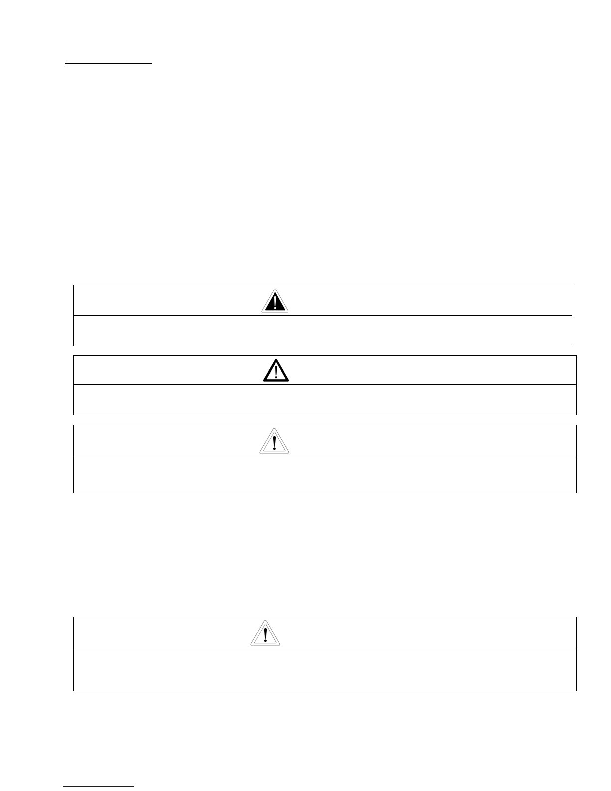
DANGER
Indicates immediate hazards which will result in severe injury or death.
WARNING
Indicates hazards or unsafe practice which could result in severe injury or death.
CAUTION
Indicates hazards or unsafe practice which could result in damage to the Champion compressor
or minor injury.
OBSERVE, UNDERSTAND, AND RETAIN THE INFORMATION GIVEN IN THE SAFETY PRECAUTION DECALS
AS SHOWN IN THE PARTS LIST SECTION.
DANGER
This Oil-Less compressor must not be used for breathing air, unless proper downstream filtraton
and purification is added. To use for breathing air without proper downstream equipment will
cause serious injury whether air is supplied direct from the compressor source or to the breathing
tanks for later use. Any and all libilities for damage or loss due to injuries, death and/or property
damage including consequential damages stemming from the use of this compressor to supply
breathing air, without proper downstream filtration and purificaton, will be disclaimed by the
manufacturer.
WARNING
The use of this compressor as a booster pump and/or to compress a medium other than
atmospheric air is strictly non-approved and can result in equipment damage and/or injury. Nonapproved uses will also void the warranty.
CAUTION
This unit may be equipped with special options which may not be included in this manual. User
must read, understand and retain all information sent with special options.
4
Page 5

INTRODUCTION
____________________________________________________________________
Your new Champion Reciprocating Air Compressor is constructed to exacting standards of material and
workmanship.
The instructions in this manual have been prepared to ensure that the Champion air compressor will give
long and satisfactory service.
A copy of this manual must be given to the personnel responsible for installing and operating the Champion
air compressor or unit.
Although precautions have been taken to prevent damage to your compressor or unit by freight carrier, the
unit must be carefully examined and the carrier notified within 24 hours in the event of mishandling.
Champion Five Year Warranty
"R" Series Compressors
CHAMPION warrants each new compressor pump manufactured by CHAMPION, mounted on a factory assembled unit,
to be free from defects in material and workmanship under normal use and service for a period of sixty (60) months from
date of installation or sixty-six (66) months from date of shipment by CHAMPION or CHAMPION distributor, whichever
may occur first. Applies to the compressor pump only, excluding head valves. Valves, controls and accessories
are warranted for the first year only. Compressor pumps purchased separately would carry a one year warranty.
This five year extended warranty will be prorated over the 5 years as follows:
First Year - 100% Allowance, Parts and Labor
Second Year - 90% Allowance, Parts and Labor
Third Year - 80% Allowance, Parts and Labor
Fourth Year - 70% Allowance, Parts and Labor
Fifth Year - 60% Allowance, Parts and Labor
Applies to CHAMPION logo, tank or base mounted complete compressors only.
Express Limited Warranty
CHAMPION warrants each new air compressor unit manufactured by CHAMPION to be free from defects in material and
workmanship under normal use and service for a period of twelve (12) months from date of installation or eighteen (18)
months from date of shipment by CHAMPION or CHAMPION distributor, whichever may occur first.
CHAMPION makes no warranty in respect to components and accessories furnished to CHAMPION by third parties, such
as ELECTRIC MOTORS, GASOLINE ENGINES and CONTROLS, which are warranted only to the extent of the original
manufacturer's warranty to CHAMPION. To have warranty consideration, electric motors must be equipped with thermal
overload protection.
The extended five year warranty will apply to ASME air receivers provided they are installed on rubber vibro isolator pads.
When a compressor pump, or component is changed or replaced during the warranty period, the new/replaced item is
warranted for only the remainder of the original warranty period.
Repair, replacement or refund in the manner and within the time provided shall constitute CHAMPION'S sole liability and
your exclusive remedy resulting from any nonconformity or defect. CHAMPION SHALL NOT IN ANY EVENT BE LIABLE
FOR ANY DAMAGES, WHETHER BASED ON CONTRACT, WARRANTY, NEGLIGENCE, STRICT LIABILITY OR
OTHERWISE, INCLUDING WITHOUT LIMITATION ANY CONSEQUENTIAL, INCIDENTAL OR SPECIAL DAMAGES,
ARISING WITH RESPECT TO THE EQUIPMENT OR ITS FAILURE TO OPERATE, EVEN IF CHAMPION HAS BEEN
ADVISED OF THE POSSIBILITY THEREOF.
CHAMPION MAKES NO OTHER WARRANTY OR REPRESENTATION OF ANY KIND, EXCEPT THAT OF TITLE, AND
ALL OTHER WARRANTIES, EXPRESS OR IMPLIED, INCLUDING WARRANTIES OR MERCHANTABILITY AND
FITNESS FOR A PARTICULAR PURPOSE, ARE HEREBY EXPRESSLY DISCLAIMED. NO SALESMAN OR OTHER
REPRESENTATIVE OF CHAMPION HAS AUTHORITY TO MAKE ANY WARRANTIES.
5
Page 6
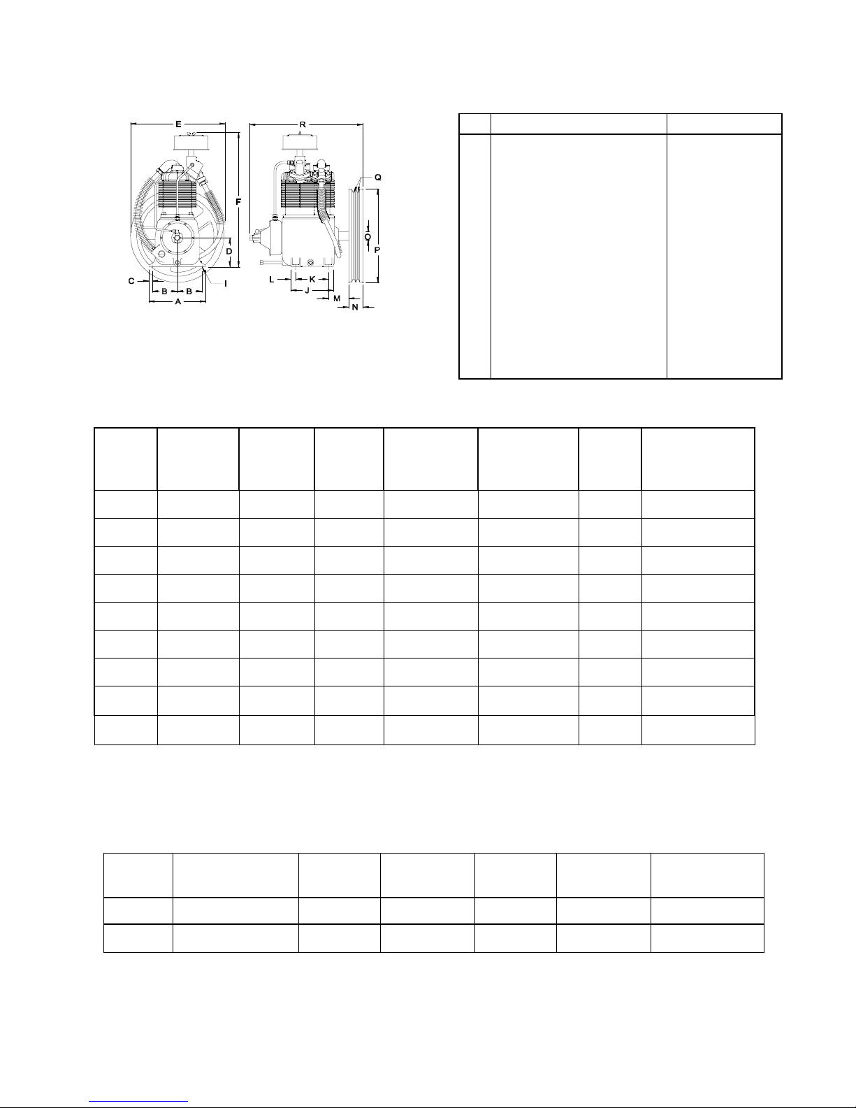
TWO STAGE AIR COMPRESSORS - MODELS R-10D & R-15B
PERFORMANCE
DIMENSIONS
ITEM R-10 & R-15
Base-Width
A
Bolt Down-Width
B
Bolt Down to Edge
C
Base to Crank Ctr
D
Overall Width
E
Overall Height
F
Bolt Down Hole Dia.
I
Base-Depth
J
Bolt Down Depth
K
Bolt Down to Edge
L
Bolt Hole to Wheel (Max.)
M
Flywheel Width
N
Crank Diameter
O
Flywheel Diameter
P
Flywheel Grooves
Q
Overall Depth
R
NOTE: H.P. Exhaust Opening 3/4" Tubing.
10
4-3/8
5/8
5½
18
23-1/4
15/32
7½
5-3/4
7/8
3-5/8
2½
1-5/16
16½
2VB
20
PUMP
OUTPUT
PRESS.
PSIG
MOTOR
H.P.
DISPL.
CFM
COOLING
AIR FLOW
CFM
HEAT
REJECTION
BTU/HR
PUMP
RPM
APPROX.
PULLEY O.D.
INCHES
R-10D 125 1-1/2 11.0 660 3360 570 5.55
R-10D 175 1-1/2 10.5 625 3360 542 5.25
R-10D 125 2 14.8 875 4480 760 7.35
R-10D 175 2 14.1 835 4480 725 7.0
R-15B 125 3 14.5 565 6700 490 4.75
R-15B 175 3 12.8 505 6700 440 4.31
R-15B 125 5 21.9 868 12,000 750 7.35
R-15B 175 5 20.7 820 12,000 710 7.00
R-15B 175 7-1/2 30.2 1195 16,800 1035 9.75
All data is based on 1725 RPM electric motors as a power source.
Flywheel Rotation; Clockwise When Min. RPM 400
Viewed From Front - Flywheel to Rear Max. RPM 1050
SPECIFICATIONS
BORE & STROKE
MODEL
R-10D 4-5/8 & 2-1/2 x 2 2 2 QT. 107 175 PSIG .01942*
R-15B 4-5/8 & 2-1/2 x 3 2 2 QT. 109 175 PSIG .02914
INCHES
* Clearance Volume Modified to Effective .014 Cu. Ft./Rev.
NO. CYLS.
OIL CAPY.
6
WT. (LBS)
MAX.
PRESS.
CU FT./REV.
Page 7
ELECTRIC WIRING (BASED ON 1999 NEC)
Wire Size (Rubber Covered) AWG NO.
Copper Conductor -- 75°C Temp Rating -- 30°C Ambient
MOTOR
3 PHASE 1 PHASE
HP
200/208V 230V 460V 575V 115V 208V 230V
1-1/2 14 14 14 14 10 14 14
2 14 14 14 14 8 12 12
3 14 14 14 14 8 10 10
5 10 (8) 12 (8) 14 (12) 14 - 8 (6) 8 (6)
7-1/2 8 (6) 10 (6) 14 (10) 14 (10) - - 6 (4)
Values in ( ) for Duplex Unit w/one incoming power line to both motors.
PIPE SIZES FOR COMPRESSED AIR LINES - R-10D & R-15B
(Based on Clean, Smooth Schedule 40 Pipe)
LENGTH OF PIPE LINES IN FEET
25 50 75 100 150 200 250 300
R-10D
3/4 3/4 3/4 3/4 3/4 3/4 3/4 3/4
R-15B
Values in ( ) for Duplex Unit.
Never use plastic pipe or improperly rated metal pipe. Improper piping materials can burst and
cause injury or property damage.
3/4 (1) 3/4 (1) 3/4(1) 3/4 (1) 1 (1-1/4) 1 (1-1/4) 1 (1-1/4) 1 (1-1/4)
7
Page 8
INSTALLATION
1. Permanently installed compressors must be located in a clean, well ventilated dry room so compressor receives
adequate supply of fresh, clean, cool and dry air. It is recommended that a compressor, used for painting, be located
in a separate room from that area wherein body sanding and painting is done. Abrasive particles or paint, found to
have clogged the air intake filters and intake valves, shall automatically void warranty.
2. Compressors should never be located so close to a wall or other obstruction that flow of air through the fan bladed
flywheel, which cools the compressor, is impeded. Permanently mounted units should have flywheel at least 12" from
wall.
3. Place stationary compressors on firm level ground or flooring. Permanent installa-tions require bolting to floor. Bolt
holes in tank or base feet are provided. Before bolting or lagging down, shim compressor level. Avoid putting a
stress on a tank foot by pulling it down to floor. This will only result in abnormal vibration, and possible cracking of
Air Receiver. It is recommended that optional vibro-isolator pads be installed on unit. Tanks bolted directly to a
concrete floor without padding will not be warranted against cracking. Champion vibro-isolators must be used for
extended warranty to apply to ASME air receivers.
4. If installing a bare pump or a base mounted unit, make certain the system has adequate pressure limiting controls.
Controls could be a pressure switch for start/stop operation or a pilot valve for continuous operation. If a pilot valve
is used, the compressor must be equipped with head unloaders. Control air must be piped from the air receiver to
the pilot valve.
DANGER
Do not install isolating valves betweencompressor outlet and air receiver. This will cause excessive
pressure if valve is closed, and cause injury and equipment damage.
WARNING
Always use an air pressure regulating device at the point of use. Failure to do so can result in injury or
equipment damage.
CAUTION
● Do not install in an area where ambient temperature is below 32 degrees F or above 100 degrees F.
● Do not install unit in an area where air is dirty and/or chemical laden.
● Unit is not to be installed outdoors.
ELECTRICAL POWER SUPPLY
It is essential that the power supply and the supply wiring are adequately sized and that the voltage correspond to
the unit specifications.
All wiring should be performed by a licensed electrician or electrical contractor. Wiring must meet applicable codes
for area of installation.
Recommended electrical wiring specifi-cations are listed in "Specifications" section.
If ordered with a mounted starter, compressor unit is pre-wired at factory. It is necessary only to bring lines
fromproperly sized disconnect switch to magnetic starter mounted on compressor, and attach to terminals as
indicated on schematic diagram located inside cover of control. Be sure that power circuit and voltage correspond
with the specifications
.
CAUTION
Wiring must be such that when viewing compressor from opposite shaft end, rotation of shaft is clockwise
as shown by arrow on guard. Wrong direction rotation for any length of time will result in damage to
compressor.
8
Page 9
INSTALLATION (CONT’D)
GROUNDING INSTRUCTIONS
This product should be connected to a grounded, metallic, permanent wiring system, or an equipment-
grounded terminal or lead on the product.
AIR LINE PIPING
Connection to air system should be of the same size, or larger, than discharge pipe out of unit. See
recommended piping sizes listed in "Specifications" section. A union connection to the unit and water drop leg
is recommended. Install a flexible connector between the discharge of the unit and the plant air piping. Plant air
piping should be periodically inspected for leaks using a soap and water solution for detection on all pipe joints.
Air leaks waste energy and are expensive.
PREPARATION FOR INITIAL START-UP AND OPERATION
1. Pull main disconnect switch to unit and tag out to assure that no power is coming into the unit. Connect
power leads to starter.
WARNING
Do not attempt to operate compressor on voltage other than that specified on order or on compressor
motor.
2. Check compressor oil level. Add oil as required. See section on "Oil Specifications".
3. Inspect unit for any visible signs of damage that would have occurred in shipment or during installation.
4. Activate main disconnect switch.
5. "Jog" motor and check for proper rotation by direction of arrow. If rotation is wrong, reverse input
connections on the magnetic starter.
6. Close receiver outlet hand valve and start unit.
7. With receiver hand valve closed, let machine pump up to operating pressure. At this stage the automatic
controls will take over. Check for proper cycling operation.
8. Check for proper operation of any options, e.g. LOSC or head unloaders with pilot valve. Refer to individual
option instruction sheet.
9. When the initial run period has shown no operating problems, shut unit down and recheck oil level.
10. Open receiver hand valve. The air compressor unit is now ready for use.
9
Page 10
GUIDE TO MAINTENANCE
To obtain reliable and satisfactory service, this unit requires a consistent preventive maintenance schedule.
Maintenance schedule pages are included in the back of this manual to aid in keeping the proper records.
WARNING
Before performing any maintenance function, switch main disconnect switch to "off" position to assure
no power is entering unit. "Lock Out" or "Tag Out" all sources of power. Be sure all air pressure in unit
is relieved. Failure to do this may result in injury or equipment damage.
DAILY MAINTENANCE
1. Check oil level of both compressor and engine if so equipped. Add quality lubricating oil as required. See
Section on "Oil Specifications".
2. Drain moisture from tank by opening tank drain valve located in bottom of tank. Do not open drain valve
if tank pressure exceeds 25 PSIG.
3. Turn off compressor at the end of each day's operation. Turn off power supply at wall switch.
WEEKLY MAINTENANCE
1. Clean dust and foreign matter from cylinder head, motor, fan blade, air lines, intercooler and tank.
2. Remove and clean intake air filters.
WARNING
Do not exceed 15 PSIG nozzle pressure when cleaning element parts with compressed air. Do not direct
compressed air against human skin. Serious injury could result. Never wash elements in fuel oil,
gasoline or flammable solvent.
3. Check V-belts for tightness. The V-belts must be tight enough to transmit the necessary power to the
compressor. Adjust the V-belts as follows:
Remove bolts and guard to access compressor drive.
Loosen mounting hardware which secures motor to base. Slide motor within slots of baseplate to desired
position.
Apply pressure with finger to one belt at midpoint span. Tension is correct if top of belt aligns with bottom
of adjacent belt. Make further adjustments if necessary.
Check the alignment of pulleys. Adjust if necessary.
Tighten mounting hardware to secure motor on base.
Re-install guard and secure with bolts.
WARNING
Never operate unit without belt guard in place. Removal will expose rotating parts which can cause
injury or equipment damage.
10
Page 11

EVERY 90 DAYS OR 500 HOURS MAINTENANCE
1. Change crankcase oil. Use type and grade oil as specified in the section on "Compressor Oil
Specifications".
2. Check entire system for air leakage around fittings, connections, and gaskets, using soap solution and
brush.
3. Tighten nuts and capscrews as required.
4. Check and clean compressor valves, replace springs, discs and seats when worn or damaged.
CAUTION
Valves must be reinstalled in original position. Valve gaskets should be replaced each time valves are
serviced.
5. Pull ring on all pressure relief valves to assure proper operation.
GENERAL MAINTENANCE NOTES
PRESSURE RELIEF VALVE: The pressure relief valve is an automatic pop valve. Each valve is properly
adjusted for the maximum pressure permitted by tank specifications and working pressure of the unit on
which it is installed. If it should pop, it will be necessary to drain all the air out of the tank in order to reseat
properly. Do not readjust.
TANK DRAIN VALVE: Drain valve is located at bottom of tank. Open drain valve daily to drain condensation.
Do not open drain valve if tank pressure exceeds 25 PSIG. The automatic tank drain equipped
compressor requires draining manually once a week.
PRESSURE SWITCH: The pressure switch is automatic and will start compressor at low pressure and stop
when the maximum pressure is reached. It is adjusted to start and stop compressor at the proper pressure
for the unit on which it is installed. Do not readjust.
BELTS: Drive belts must be kept tight enough to prevent slipping. If belts slip or squeak, see V-belt
maintenance in preceding section.
CAUTION
If belts are too tight, overload will be put on motor and motor bearings.
COMPRESSOR VALVES: If compressor fails to pump air or seems slow in filling up tank, disconnect unit from
power source and remove valves and clean thoroughly, using compressed air and a soft wire brush. After
cleaning exceptional care must be taken that all parts are replaced in exactly the same position and all
joints must be tight or the compressor will not function properly. When all valves are replaced and
connections tight, close hand valve at tank outlet for final test. Valve gaskets should be replaced each time
valves are removed from pump.
11
Page 12

GENERAL MAINTENANCE NOTES (CONT'D)
CENTRIFUGAL UNLOADER AND UNLOADER PRESSURE RELEASE VALVE:
The centrifugal unloader Is operated by two governor weights. It is totally enclosed and lubricated from
the crankcase of the compressor. When compressor starts, the governor weights automatically open
compressing the main spring, allowing the unloader pressure release valve to close. When the compressor
stops, the main spring returns the governor weights to normal position opening the unloader pressure
release valve and unloading the compressor. This prevents overloading the motor when starting. If air
continues to escape through the governor or unloader pressure release valve while operating, this is an
indication that the unloader pressure release valve is not closing tightly and may be held open by foreign
substance which has lodged on the seat. In order to correct this, remove the governor release valve cap,
giving access to unloader pressure release valve spring and ball. Clean thoroughly and return parts in the
same order in which they were removed. Loose drive belts can also cause unloader to leak by preventing
the compressor from reaching proper speed. (See "BELTS" above.)
CHECK VALVE:
The check valve closes when the compressor stops operating, preventing air from flowing out of the tank
through the pressure release valve. After the compressor stops operating, if air continues to escape
through the release valve, it is an indication that the check valve is leaking. This can be corrected by
removing check valve and cleaning disc and seat. If check valve is worn badly, replace same.
WARNING
Before removing check valve be sure all air pressure in unit is relieved and power is disconnected. Failure
to do so may result in injury or equipment damage.
THE INTERSTAGE PRESSURE RELIEF VALVE is provided to protect against interstage over pressure and is
factory set for maximum pressure of 75 PSIG.
DO NOT RESET
If the pressure relief valve pops, it indicates trouble. Shut down the unit immediately and determine and
correct the malfunction. Inspect the head valves. Serious damage can result if not corrected and can lead
to
complete destruction of the unit. Tampering with the interstage pressure relief valve, or plugging the
opening destroys the protection provided and voids all warranty.
LUBRICATION OF COMPRESSOR:
Fill crankcase to proper level as indicated by oil sight gauge. Keep crankcase filled as required by usage.
12
Page 13

COMPRESSOR OIL SPECIFICATIONS
1. AIR COMPRESSOR
Compressors shipped on units are factory filled with ISO 100 reciprocating compressor oil. Compressors
shipped as basic (pump only) do not have any oil in the crankcase. Be sure to add oil to these pumps prior
to start-up.
It is recommended that this compressor be maintained using the ISO 100 recip oil for ambient
temperatures above 32 degrees F. This is a 30 weight, non-detergent industrial oil with rust and oxidation
inhibitors specially formulated for reciprocating compressors. Contact your distributor for information and
purchase of this oil. For temperatures below 32 degrees F, use an ISO 68 compressor oil. A separate
list of acceptable oils can be obtained from the distributor's Service Department.
NOTES:
1. Do not mix oil types, weights, or brands. Consult factory for the use of synthetic lubricants.
2. For the first 100 hours of compressor operation, a careful and regular check of the oil level should
be made. Maintain oil level at the full line.
2. ELECTRIC MOTORS
Electric motors are equipped with sealed-for-life bearings and require no additional lubrication.
13
Page 14

TROUBLE SHOOTING CHART FOR COMPRESSOR
Always disconnect unit from power supply and relieve all pressure from air tank before
performing any maintenance. Failure to do so may result in equipment damage or injury.
ALock Out" or "Tag Out" all power sources.
WARNING
Never operate unit without belt guard in place.
Never use gasoline or flammable solvent on or around compressor unit. Explosion may
result.
SERVICE PROBLEM
A Motor will not Start
B Motor is Noisy or Overheats
C Motor Stops
D Compressor Runs Hot
E Compressor Pumps Too Slowly
F Compressor Won't Shut Off
G Noisy Check Valve
H Excessive Belt Wear
I Abnormal Pressure Fluctuation
J Air Escapes From Unloader Muffler When Running
K Air Escapes From Unloader Muffler When Stopped
L Interstage Pressure Relief Valve Pops Off Continuously
M Compressor Cycles (runs) too Often
N Starter Kicks Out
POSSIBLE CAUSE OF PROBLEM
1 Main Switch and Fuses Open 1
2 Magnetic Starter Heater Coils Open 2
3 Magnetic Starter Tripped 3
4 Points in Pressure Switch Defective 4
5 Diaphragm in Pressure Switch Bad 5
6 Low Voltage 6
7 Motor Lubrication Inadequate 7
8 Excess Water in Air Receiver 8
9 Dirty Aftercooler; Cylinder and Intercooler 9
10 "V" Belts Improperly Tensioned 10
11 Improper Flywheel Rotation 11
12 Compressor Pump Valves Defective 12
13 Pipe Line Leaks 13
14 Misadjustment of Pilot Valve - This is for
optional parts.
15 Pilot Valve Leaks - This is for optional parts. 15
NMLKJIHGF EDCB A
14
16 Centrifugal Unloader Valve is Leaking 16
17 Check Valve is Leaking 17
18 Check Valve is Worn 18
19 Check Valve or Line to Tank is Plugged 19
20 Misaligned Belts 20
21 Dirty Intake Filter 21
22 Low Crankcase Oil Level 22
FOR EXPLANATION SEE NEXT PAGE
NMLKJIHGF EDCB A
14
Page 15

EXPLANATION OF TROUBLE SHOOTING GUIDE
1/2. Check all fuses and switches on lines to motor to be sure it is receiving power. Check for loose or
faulty wires.
3. A magnetic starter embodies a reset button which may be used to place the motor back in service
after some unusual power conditions.
4/5. A pressure switch uses a diaphragm to open and close a set of points. Points may become pitted
or dirty through use. Clean by "touching up" with sandpaper or replace. See instructions in pressure
switch cover.
WARNING
Disconnect unit from power source before checking pressure switch.
6. Low voltage is prime cause of motor trouble. Ask you power company to test for low voltage.
7. Most electric motors are of the sealed bearing type. Check motor manufacturer's recommendation.
8. Water in the form of vapor is compressed along with incoming air and condenses in tank. Tank must
be drained daily so that full storage capacity of tank may be used. To drain, relieve tank pressure,
open valve at bottom of horizontal or vertical tank. If compressor is equipped with automatic tank
drain, drain manually once a week.
WARNING
Do not open drain valve if tank pressure exceeds 25 PSIG.
9. The fins on the cylinder and tubing should be free of dirt which acts as an insulation. This is easily
done by periodically blowing them clean or through the use of a wire brush.
9. "V” belts must be tight enough to transmit the necessary power to the compressor. If too tight they
will overload the motor. If, by pushing down on one belt, its top lines up with the bottom of the belt
next to it, the tension is correct. Should it be necessary to change the tension, slide the engine or
motor in slots provided in tank baseplate to desired position.
WARNING
Disconnect unit from power source before checking or adjusting belts. Always reinstall belt guard
after adjusting belts.
11. The fan blade flywheel must rotate in the direction shown by the arrows.
12. Compressor valves may become fouled by carbon or other foreign matter. To service, remove
manifold and extract valve. Remove screw in center of valve and clean all parts. Seat and disc may
be lapped in on fine sandpaper if badly carboned. If a smooth finish cannot be obtained, replace with
new parts. Reassemble and install, taking caution that all parts are returned to their original position
with screw head up.
13. All air lines from compressor to tank and from tank to air operated devices should be tight. A soap
solution will show bubbles when put on a leaky joint. At 175 PSIG a 1/32" hole will allow almost 3
cubic feet per minute of air to escape.
14. Pilot Valve adjustment is found on page 23.
15. Check pilot valve for loose connections.
16. The centrifugal unloader valve may become fouled by foreign matter. To clean, unscrew hex cap on
end of unloader, remove spring and ball, to remove ball, you may need to "rock" flywheel. Clean or
replace if necessary.
15
Page 16

EXPLANATION OF TROUBLE SHOOTING GUIDE (CONT'D.)
17/18. Before servicing check valve, be sure pressure in tank is ZERO. Replace check valve.
19. Badly worn compressors which are pumping oil may deposit carbon within after-cooler tube and check
valve, restricting flow of air and possibly plugging these parts completely. These parts should be
cleaned or replaced.
WARNING
Disconnect unit from power source and relieve tank pressure before servicing these components.
20. Motor pulley and flywheel must be in line to prevent wear on sides of belts. If misaligned, disconnect
unit from power source and move pulley in or out by loosening set screw on key and tapping pulley
in appropriate direction.
WARNING
Disconnect power source before adjusting pulley.
21. Intake filter should be cleaned periodically to allow unrestricted flow of entering air. To service filter,
remove wing nut, metal cover and filter element. Element may be blown clean with an air nozzle if
moderately dusty. Heavily fouled elements should be replaced. Never clean element with fuel oil,
gasoline or flammable solvent.
22. Cool running and long life can be assured by careful attention to crankcase oil. Check frequently and
change as indicated on compressor data sheet.
_____________________________________________________________________________
PARTS LIST
MAJOR COMPRESSOR UNIT COMPONENTS
Parts common to all models except base mounted :
7) Pressure Switch - M1227
8) Pressure Relief Valve - M2843
9) Pressure Gauge - M519C
10) Drain Valve - M2684
11) Check Valve - P05822A
12) Tank Drain - Z1542 - Horizontal Tank
- Z1541 - Vertical Tank
13) Belt Guard - Z-307
(All units except those equipped with air-cooled
aftercoolers)
Additional parts for Duplex Unit (Not Shown)
• Alternator Class 47, 208V, 3 Phase; P10043A
230V, 3 Phase; P05814A
460V, 3 Phase; P05815A
• Magnetic Starter (2), Specify Voltage & Phase
16
Page 17

PARTS LIST CONT'D
HORIZONTAL TANK MODEL ILLUSTRATED (See Preceding Page)
12 34 5
Model
Number Pump
HR1-3
HR1-6
HR1-8
HR2-3
HR2-6
HR2-8
HR3-6
HR3-8
HR3-12
HR5-6
HR5-8
HR5-12
HR5D-12
VR1-6
VR1-8
VR2-6
VR2-8
R-10D
R-10D
R-10D
R-10D
R-10D
R-10D
R-15B
R-15B
R-15B
R-15B
R-15B
R-15B
R-15B (2)
R-10D
R-10D
R-10D
R-10D
Elec.
Motor Air Tank
12 HP
12 HP
12 HP
2 HP
2 HP
2 HP
3 HP
3 HP
3 HP
5 HP
5 HP
5 HP
5 HP (2)
1-1/2HP
1-1/2HP
2 HP
2 HP
P04390D
P01136D
P01164D
P04390D
P01136D
P01164D
P01136D
P01164D
P01596D
P01136D
P01164D
P01596D
P02080D
P01161D
P01217D
P01161D
P01217D
Motor Pulley
(Not Shown)
Hand
Valve 1 Phase 3 Phase V-Belts
M3590
M3590
M3590
M3590
M3590
M3590
M3590
M3590
M2686
M3590
M3590
M2686
M2686
M3590
M3590
M3590
M3590
P09315B
P09315B
P09315B
M7009D
M7009D
M7009D
M4309D
M4309D
M4309D
M7009D
M7009D
M7009D
M7009D
P09315B
P09315B
M7009D
M7009D
P09315B
P09315B
P09315B
P11703A Pulley
P09423A Bushing
P11703A Pulley
P09423A Bushing
P11703A Pulley
P09423A Bushing
M4309D
M4309D
M4309D
M7009D
M7009D
M7009D
M7009D
P09315B
P09315B
P11703A Pulley
P09423A Bushing
P11703A Pulley
P09423A Bushing
6
4L-650
4L-650
4L-650
4L-680
4L-680
4L-680
5L-650
5L-650
5L-650
5L-680
5L-680
5L-680
5L-680 (4)
4L-650
4L-650
4L-680
4L-680
VR3-6
VR3-8
VR3-12
VR5-6
VR5-8
VR5-12
BR-1
BR-2
BR-3
BR-5
HR7F-8
HR7F-12
HR7DF-25
VR7F-8
VR7F-12
BRF-7
R-15B
R-15B
R-15B
R-15B
R-15B
R-15B
R-10D
R-10D
R-15B
R-15B
R-15B
R-15B
R-15B(2)
R-15B
R-15B
R-15B
* "BR" units are not supplied with tanks. Baseplate P09195C is common to all models.
3 HP
3 HP
3 HP
5 HP
5 HP
5 HP
12 HP
2 HP
3 HP
5 HP
7-1/2 HP
7-1/2 HP
7-1/2 HP (2)
7-1/2 HP
7-1/2 HP
7-1/2 HP
P01161D
P01217D
P02212D
P01161D
P01217D
P02212D
*
*
*
*
PO1164D
P01596D
P05763D
P01217D
P02212D
*
M3590
M3590
M2686
M3590
M3590
M2686
*
*
*
*
M3590
M2686
M2686
M3590
M2686
*
M4309D
M4309D
M4309D
M7009D
M7009D
M7009D
P09315B
M7009D
M4309D
M7009D
P07981A - Pulley
P05607A - Bushing
P07981A - Pulley
P05607A - Bushing
P07981A - Pulley
P05607A - Bushing
P07981A - Pulley
P05607A - Bushing
P07981A - Pulley
P05607A - Bushing
P07981A - Pulley
P05607A - Bushing
M4309D
M4309D
M4309D
M7009D
M7009D
M7009D
P09315B
P11703A Pulley
P09423A Bushing
M4309D
M7009D
P07981A - Pulley
P05607A - Bushing
P07981A - Pulley
P05607A - Bushing
P07981A - Pulley
P05607A - Bushing
P07981A - Pulley
P05607A - Bushing
P07981A - Pulley
P05607A - Bushing
P07981A - Pulley
P05607A - Bushing
5L-650
5L-650
5L-680
5L-680
5L-680
4L-650
5L-680
5L-650
5L-680
5L-680
B68
B68
B68 (4)
B68
B68
B68
17
Page 18

R-10D AND R-15B
FLYWHEEL, CYLINDER, CRANKCASE & UNLOADER ASSEMBLY
ITEM PART NO. NAME REQ. ITEM PART NO. NAME REQ.
1
4
1
1
1
2
2
1
1
1
1
1
1
1
6
1
1
1
1
1
1
10
11
12
13
14
15
16
17
18
1
2
3
4
5
6
7
8
9
P12237D
M2345
NR29A
NR7A
U8
M738
M465
M1820
M2326
RE714
M459
M492
M461
Z130
SE1430
SE1430A
SE1430B
SE1430C
Cylinder
Screw, Hex Head Cap
Gasket, Cylinder
Flange
Flywheel
Key
Screw, Hex Head Cap
Nut, Hex
Crankcase
Pipe Plug
Gauge, Oil Level
Pipe Plug (Oil Fill)
Pipe, Oil Drain
Cap, Oil Drain
Gasket Set, Gov.
Housing
Gasket, Gov. Housing
(.030" Thick)
Gasket, Gov. Housing
(.005" Thick)
Gasket, Gov. Housing
(.010" Thick)
Gasket, Gov. Housing
(.015" Thick)
1
6
1
1
1
1
1
1
1
1
1
1
1
1
1
1
1
1
19
20
21
22
23
24
25
26
27
28
29
30
31
32
33
34
35
36
37
38
NR80A
M2343
SE1489
NR104
SE583B
SE582
SE 592A
M466
M2345
M912A
SE590
SE587
RE10100A
Z4593
M3473
Z12414A
SE586B
P07841A
SE591
NR101
Z764
Gov. Housing
Screw, Hex Head Cap
Gasket, Gov Housing Cover
Plate, Gov Baffle
Spindle, Gov. Wt.
Gov. Wt.
Pin. Gov. Wt.
Washer, Spring Lock
Screw, Hex Head Cap
Washer, Flat
Spring, Gov. Main
Sleeve, Spring
Cover, Gov. Housing
MUFFLER ASSY, UNLOADER
Screw, Hex Head Machine
RELEASE VALVE ASSY. KIT
Plunger, Release Valve
Ball Release Valve
Spring, Release Valve
Body, Release Valve
GASKET SET, COMPLETE PUMP
18
Page 19

R-10D AND R-15B
CRANKSHAFT, PISTONS, CONNECTING ROD ASS'YS.
ITEM PART
NO.
1
2
3
4
5
6
7
R105
R155
ZNR16
OSN4
Z750
Z752
NSS
M1583
R1024
R1524
NAME REQ ITEM PART
Crankshaft (R-10D only)
Crankshaft (R-15B only)
ASSY; Main Bearing
Oil Seal
KIT, CONNECTING ROD ASSY.
(Items 5,6,7 & 8)
R-15B, Low Pressure & High Pressure
R-10D, Low Pressure
KIT, CONNECTING ROD ASSY.
(Items 5,6,7 & 8)
R-10D, High Pressure (side only)
Connecting Rod
Bolt, Connecting Rod
Dipper, Oil (R-10D only)
Dipper, Oil (R-15B only)
NOTE: NSS= Not Sold Separately
NAME REQ
NO.
1
1
2
1
2
1
1
4
2
2
8
9
10
11
12
13
14
R1037
ZR154
ZP2709C
R1021
R10102
Z797
Z798
Z9100
Z9101
Z799
Bearing, Piston Pin
Piston, Low Pressure w/Pin
Piston, High Pressure w/Pin
Pin, Piston
Ring, Piston Pin Retaining
RING SET, HIGH PRESSURE PISTON
RING SET, LOW PRESSURE PISTON
KIT, HIGH PRESSURE PISTON ASSY.
(Items 10, 11, 12 & 13)
KIT, LOW PRESSURE PISTON ASSY.
(Items 9, 11, 12 & 14)
KIT, COMPLETE RING SET
(Items 13 & 14)
2
1
1
2
4
1
1
1
1
1
19
Page 20

R-10D AND R15B
VALVES & FILTER, MANIFOLD ASS'YS.
ITEM PART NO. NAME REQ. ITEM PART NO. NAME REQ.
1
1
1
1
1
1
1
1
1
8
3
3
1
1
1
1
1
1
1
1
10
11
12
13
14
15
16
17
18
19
20
21
22
1
2
3
4
5
6
7
8
9
P04544A
RE1471A
RE1470
RE1458
M2098
P04134A
M3220
P04135A
M2099
RE1059
RE1061
M2097
P04135A
M3220
P09191A
P09172B
RE1062
RE760
M2101
P09170A
M3220
P04137A
Screw, Hex Head Machine
Seat, Intake Valve
Disc, Valve
Spring, Valve
Cage, Intake Valve
Gasket, Valve
Screw, Hex Head Machine
Gasket, Valve
Cage, Exhaust Valve
Spring, Exhaust Valve
Disc, Valve
Seat, Exhaust Valve
Gasket, Valve
Screw, Hex Head Machine
Gasket, Valve
Seat, Intake Valve
Disc, Valve
Spring, Valve
Cage, Intake Valve
Gasket, Valve
Screw, Hex Head Machine
Gasket, Valve
1
1
1
1
1
1
1
1
1
1
1
1
1
1
1
1
1
1
1
1
1
1
23
24
25
26
27
28
29
30
31
32
33
34
35
36
37
38
39
40
41
42
M2100
RE760
RE1062
RE757A
P04136
RE102E
P12303B
P09669C
P12302B
P05005A
SE542
SE541
P04999A
P05050A
P03592A
P09704A
Z812
Z813
Z5117
Z115
Z5155
Z5156
Cage, Exhaust Valve
Spring, Valve
Disc, Valve
Seat, Exhaust Valve
Gasket, Valve
Manifold, LP Exhaust
Manifold, HP Exhaust
Manifold, LP Intake
Manifold, HP Intake
Screw, Hex Head Cap (All Manifolds)
Ferrule
Nut, compression
Intake Filter
Filter Element
Interstage Pressure Relief Valve
Pressure Relief Valve
VALVE ASSY, LP INTAKE*
VALVE ASSY, LP EXHAUST
VALVE ASSY, HP INTAKE*
VALVE ASSY, HP EXHAUST
COMPLETE VALVE SET w/GASKETS*
COMPLETE VALVE GASKET SET
* See page 18, Unloader Kit, for intake valves for head unloader pumps. Use Z6795 - Complete Valve Set for Head Unloader Pumps.
20
Page 21

R10D AND R-15B
INTERCOOLER & TUBING
ITEM PART NO. NAME REQ.
1
2
3
4
5
6
7
M2863
ZSB250A
M2864
ZUB375
M2864
M2868
Z9140
Compression Fitting
Tube, Unloading w/Fittings
Compression Fitting
Breather Tube w/Fittings
Compression Fitting
Compression Fitting
Intercooler w/Fittings
1
1
1
1
1
1
1
21
Page 22

CONSTANT SPEED HEAD UNLOADER KIT Z9144
For Air Compressor Pump Models R-10D and R-15B
NOTE: This is optional equipment and may not be included on your unit.
The purpose of constant speed unloading is to provide a means of stopping or starting the compression of air by the compressor
without stopping or starting the electric motor or gasoline engine after each cycle.
To accomplish this, an air pilot valve is used to replace the pressure switch used for stop-start operation. The pilot valve senses
storage tank pressure, and when the pressure is raised to a predetermined setting, this air is released to an intake valve hold-open
mechanism. The compressor stops compressing air and runs free until the pilot valve senses that the pressure in the tank has
dropped to the predetermined setting. At this time the air is released from the intake valve hold-open mechanism, and the
compressor starts compressing air again.
The parts called out below replace or are substituted for those found in the regular parts list.
Z9144 - CAPTURED UNLOADER VALVE
R-10D, R-15B
TYPICAL MINIFOLD ASSEMBLY
FOR HEAD UNLOADERS
REF. NO. TOTAL
REQ'D
1
2
3
4
5
6
7
8
9
1
1
1
1
1
1
1
1
1
1
REF. NO. TOTAL
REQ
-
1
2
3
4
5
6
7
8
9
10
11
REF.
NO.
1
1
1
1
1
1
1
1
1
1
1
1
TOTAL
REQ'D
PART NO. LOW PRESSURE
Z6312
P09670C
P02306B
P09923A
P02547A
Z4877
P09085A
P09084A
P09086A
P09083A
LP Intake Manifold Group (includes 1,2,3,4)
LP Intake Manifold
Cylinder
Unloader Piston
O-Ring
LP Valve Assembly
(includes 6,7,8,9)
Unloader Finger
Unloader Spring
Locknut
Guide Stem
PART NO. HIGH PRESSURE
Z9143 HP
Z9143
P12304B
P02306B
P09923A
P02547A
Z6308
P09297A
P01882A
P09086A
P09296A
P00746A
P09171A
HP Intake Manifold Goup
(Includes items 1,2,3,4,10)
HP Intake Manifold
Cylinder
Unloader Piston
O-Ring
HP Valve Assembly
(includes 6,7,8,9)
Unloader Finger
Unloader Spring
Locknut
Guide System
Cylinder Gasket
Valve Gasket
(not included)
PART NO. HIGH & LOW PRESSURE
12
13
14
15
16
17
18
19
20
1
1
1
1
1
1
1
1
1
M2879
Z9172
M2868
P12323A
M2853
M2881
M3465
M807
M2868
Compression Fitting
Manifold Tube
Compression Fitting
Actuating Tube
Pilot Valve
Compression Fitting
Screw, Hex Head Cap
Mounting bracket
Compression Fitting
22
Page 23

OPERATION AND ADJUSTMENT OF PILOT VALVES
B980-B
(Ref. Drawing)
PILOT VALVES
ASSEMBLY
PART NO.
M2855
M2854
M2853
PRESSURE RANGE,
PSIG
75 - 95
90-120
140 - 170
The Pilot Valve is designed to act as an automatic "on" and "off" air switch. When in the "on" position it allows air to flow
from the tank through the valve to some device such as a compressor suction unloader, thus actuating it. In the "off"
position this valve stops the flow of air through the valve and releases the pressure in the line to the device.
The Pilot Valve works as follows: Tank air pressure acts on the bottom of the valve. When pressure is great enough
to overcome spring force holding valve down on lower seat, it lifts off seat and allows air to flow around valve and out
through side opening in Pilot Valve. When valve lifts off lower seat it moves up and seats on upper seat where it is held
by tank pressure. When pressure in tank and on valve drops, spring forces valve back down on lower seat. Air in line
to device being actuated can then escape through upper seat and out vent hole. The pressure at which the Pilot Valve
is "on" or "off" is controlled by the spring which has been installed at the factory. A small adjustment can be made in
the field by changing the spring force by compressing the spring more or less with the adjusting screw provided on the
Pilot Valve.
COMPRESSOR PILOT VALVEPRESSURE ADJUSTMENT
Proceed with the following instructions while compressor is running:
1. Loosen locknut (4) and back off several turns. Do not turn differential adjuster (3).
2. Check reading on the tank pressure gauge. Set the compressor maximum pressure at 170 psig. Turn threaded
cap clockwise to increase pressure or counterclockwise to decrease pressure.
3. After pressure is set, tighten locknut (4). Be careful not to move the threaded cap (1).
COMPRESSOR PILOT VALVE DIFFERENTIAL PRESSURE ADJUSTMENT
Proceed with the following instructions while compressor is running:
1. Loosen locknut (2) and back off several turns.
2. Check reading on the tank pressure gauge. Set the pressure to 30 psig differential (unload at 170 psig, reload
at 140 psig). Turn nut (3) clockwise to increase differential pressure or counter-clockwise to decrease differential
pressure.
3. After pressure is set, tighten locknut (2). Be careful not to move nut (3).
23
Page 24

UNIT HAZARD DECAL LISTING
ITEM DESCRIPTION PART NO.
A
B
C
D
E
F
G
H
I
J
K
L
M
N
O
P
Q
R
S
T
Retain Labels
DANGER - Breathing Air
DANGER - Drain Tank Daily
DANGER - Valve Maintenance
DANGER - High Voltage
DANGER - Auto Start
WARNING - Pressure/Safety Valve
WARNING - Rotating Parts
WARNING - Hot Surfaces
WARNING - Tank Pressure
CAUTION - Clean Filters
Unit Location
Rotation Direction
Pressure Setting: Master
Pressure Setting: 140-175 psig
Maintenance Instructions
*Dual Control Valve
*Low Oil Safety Control
*Automatic Tank Drain
Service Information
P09879A
P09376B
P09430B
P09750B
P04934A
P09384B
P09752B
P09373B
P09758A
P04983A
M1736
P04518A
M422
P09388A
P04988A
P09755B
P05381A
P02134A
M653
P04995A
U
V
W
1
2
3
4
5
6
*For Optional Parts
UNIT HAZARD TAG LISTING
IMPORTANT - Electrical Specs
DANGER - Valve Instructions
WARNING - Read Owners Guide
PUMP HAZARD DECAL & TAG LISTING
DECAL - Retain Labels
DECAL - DANGER- Adequate Filtering
DECAL - Rotation Direction
DECAL - Service Filter
TAG - DANGER - Valve Instructions
TAG - WARNING - Read Owners Guide
P05257A
P09852A
P04996A
PO9879A
PO8586A
M442
M1736
PO9852A
PO4996A
24
Page 25

A
B
C
UNIT HAZARD DECALS & TAGS
G
D
E
H
I
J
F
25
Page 26

K
L
M
N
S
T
U
O
P
Q
140-175 PSIG
V
R
W
26
Page 27

PUMP HAZARD DECALS & TAGS
1
2
3
4
5
6
27
Page 28

RECORD OF MAINTENANCE SERVICE
DAILY
● CHECK OIL LEVEL
● DRAIN MOISTURE FROM TANK
WEEKLY
● CLEAN FILTER
● CLEAN COMPRESSOR
● CHECK V-BELTS
MONTHLY
● INSPECT AIR SYSTEM
EVERY 3 MONTHS
● CHANGE OIL
● INSPECT VALVE ASSEMBLIES
● TIGHTEN ALL FASTENERS
● TEST PRESSURE RELIEF VALVE
28
Page 29

RECORD OF MAINTENANCE SERVICE
DAILY
● CHECK OIL LEVEL
● DRAIN MOISTURE FROM TANK
WEEKLY
● CLEAN FILTER
● CLEAN COMPRESSOR
● CHECK V-BELTS
MONTHLY
● INSPECT AIR SYSTEM
EVERY 3 MONTHS
● CHANGE OIL
● INSPECT VALVE ASSEMBLIES
● TIGHTEN ALL FASTENERS
● TEST PRESSURE RELIEF VALVE
29
Page 30

RECORD OF MAINTENANCE SERVICE
DAILY
● CHECK OIL LEVEL
● DRAIN MOISTURE FROM TANK
WEEKLY
● CLEAN FILTER
● CLEAN COMPRESSOR
● CHECK V-BELTS
MONTHLY
● INSPECT AIR SYSTEM
EVERY 3 MONTHS
● CHANGE OIL
● INSPECT VALVE ASSEMBLIES
● TIGHTEN ALL FASTENERS
● TEST PRESSURE RELIEF VALVE
30
Page 31

Page 32

FOR PARTS: REFER TO PARTS DEPOT LIST
ACCOMPANYING THIS MANUAL.
www.championpneumatic.com
Champion
1301 North Euclid Avenue
Princeton, Illinois 61356 USA
Phone (815) 875-3321
Fax (815) 872-0421
Copyright 8 2000 Gardner Denver, Inc.
Printed in U.S.A.
E-mail: champion@championpneumatic.com
Plants in Princeton, IL, and Manteca, CA
Due to Champion=s continuing product development program,
specifications and materials are subject to change without notice or obligation
31
 Loading...