

Champion PR36 Installation Manual

PR/TR
Relief or Intake Ventilators
INSTALLATION, OPERATION, AND MAINTENANCE MANUAL
This publication contains the installation instructions for standard units of the PR/TR - Relief or Intake
Ventilator. Carefully read this publication prior to any
installation procedure.
Loren Cook catalog, Gravity, provides additional informa-
tion describing the equipment, unit performance, available
accessories, and specification data.
For additional safety information, refer to AMCA publication 410-96, Safety Practices for Users and Installers of
Industrial and Commercial Fans.
All of the publications listed above can be obtained from
Loren Cook Company by phoning 417/869-6474, extension
166; by FAX at 417/832-9431; or by e-mail at info@lorencook.com.
For information and instructions on special equipment,
contact Loren Cook Company at 417/869-6474.
Receiving and Inspection
Immediately upon receipt of a PR/TR unit, carefully
inspect it for damage and shortage.
• Check dampers (if supplied) for free operation of all
moving parts.
• Record on the Delivery Receipt any visible sign of damage.
b) Secure to curb at damper shelf.
c) When motorized damper kits are supplied, follow
installation instructions provided with kit. Drill hole in
curb shelf for wiring (if needed).
Unit Installation
Secure ventilator to curb using lag screws, anchor bolts,
or suitable fasteners.
(continued on back)
PR
Handling
Lift the unit by the base or shipping carton. Never lift by
the tiers.
Storage
If the unit is stored for any length of time prior to installation, store it in its original shipping crate and protect it from
dust, debris and the weather.
Installation
Damper Installation
If your unit is supplied with dampers, follow the directions
below. If your unit does not include dampers, proceed to unit
installation.
When dampers are supplied:
a) Place dampers inside the curb, ensuring that the
damper will open freely in the correct direction of airflow.
TR
1
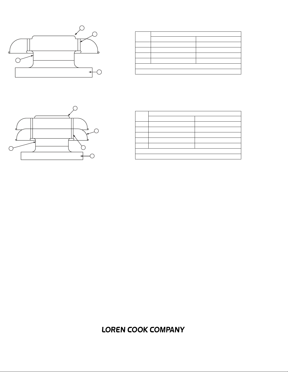
PR Parts List
4
TR Parts List
5
1
2
Part
No.
Sizes 8 - 30 Sizes 36 - 48
Description
1 Topcap Topcap
2 Post (4) Post (8)
3 Base Base
4Inlet Inlet
Not Shown
3
1
Part
No.
Birdscreen (optional)
Description
Sizes 8-30 Sizes 36 - 48
1 Topcap Topcap
2
2 Open Tiered Topcap Open Tiered Topcap
3 Post (8) Post (16)
4 Base Base
3
4
5Inlet Inlet
Not Shown
Birdscreen (optional)
Limited Warranty
Loren Cook Company warrants that your Loren Cook fan was manufactured free of defects in materials and workmanship, to the extent stated herein. For a period of five (5)
years after date of shipment, we will replace any parts found to be defective without charge, except for shipping costs which will be paid by you. This warranty is granted only
to the original purchaser placing the fan in service. This warranty is void if the fan or any part thereof has been altered or modified from its original design or has been abused,
misused, damaged or is in worn condition or if the fan has been used other than for the uses described in the company manual. This warranty does not cover defects resulting
from normal wear and tear. To make a warranty claim, notify Loren Cook Company, General Offices, 2015 East Dale Street, Springfield, Missouri 65803-4637, explaining in
writing, in detail, your complaint and referring to the specific model and serial numbers of your fan. Upon receipt by Loren Cook Company of your written complaint, you will be
notified, within thirty (30) days of our receipt of your complaint, in writing, as to the manner in which your claim will be handled. If you are entitled to warranty relief, a warranty
adjustment will be completed within sixty (60) business days of the receipt of your written complaint by Loren Cook Company. This warranty gives only the original purchaser
placing the fan in service specifically the right. You may have other legal rights which vary from state to state.
Corporate Offices: 2015 E. Dale Street Springfield, MO 65803 417.869.6474
www.lorencook.com
2
PR/TR IOM - March 2005
 Loading...