

Page 1

Tall Hood-type
LISTED
Dishwashers
Installation, Operation, Cleaning and Maintenance Manual
M1.5 Series
Models:
DH5000T, MDHHD
Hot water sanitizing machine w/fresh
water rinse and built-in stainless steel
electric booster
Options:
Ventless Heat Recovery
Issue Date: 2.24.16
Manual P/N 115744 rev. B
For machines beginning with S/N D150712934 and above
3765 Champion Boulevard
Winston-Salem, NC 27105
(336) 661-1556 Fax: (336) 661-1660
Toll-free: 1 (800) 858-4477
2674 N. Service Road, Jordan Station
Ontario, Canada L0R 1S0
(905) 562-4195 Fax: (905) 562-4618
Toll-free: 1( 800) 263-5798
Printed in the USA
Page 2
National Service Department
In Canada: In the USA:
Toll-free: (800) 263-5798 Toll-free: (800) 858-4477
Tel: (905) 562-4195 Tel: (336) 661-1556
Fax: (905) 562-4618 Fax: (336) 661-1660
email: service@moyerdiebellimited.com email: service@championindustries.com
ATTENTION
The model no., serial no., voltage, Hz
and phase are needed to identify your
machine and to answer questions.
The machine data plate
is located on the right front corner
of the lower panel
Please have this information ready
if you call for service assistance.
The USGBC and the CaGBC Member Logos are trademarks owned by the U.S. Green Building Council and The Canadian Green Building Council,
respectively, and are used by permission. The logos signify only that Champion Industries, and Moyer Diebel are USGBC and a CaGBC members;
USGBC and CaGBC do not review, certify nor endorse the products or services offered by its members.
COPYRIGHT © 2016 All rights reserved Printed in the USA
Page 3
Product Registration
Three ways to
REGISTER YOUR PRODUCT and
ACTIVATE YOUR WARRANTY.
4:34 PM 44%
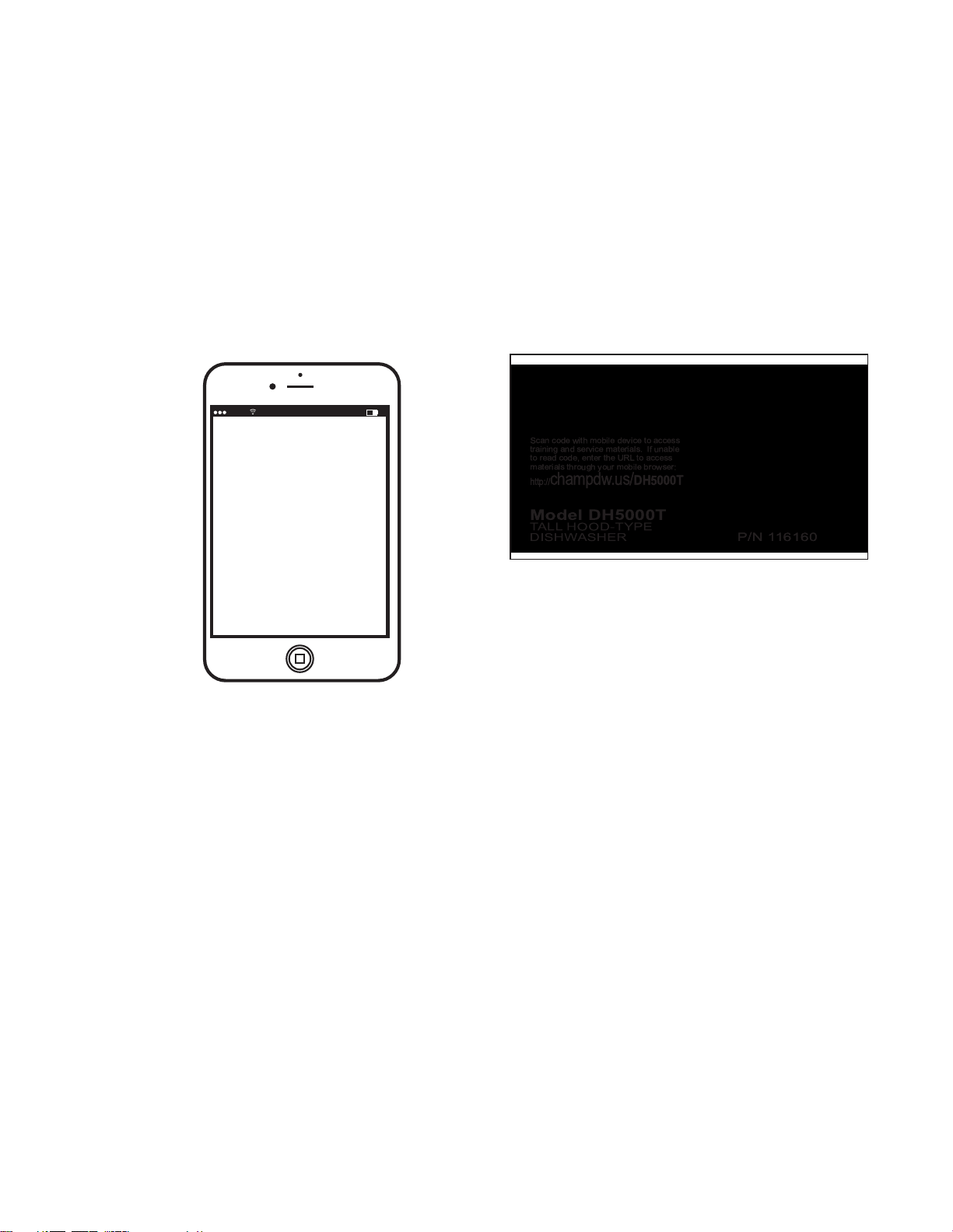
The QR website is an excellent resource for operators
and service agents.
• Use your mobile device to scan the QR code located on the front panel
of your machine or enter our URL http://www.champdw.us/DH5000T.
• Visit our website at www.championindustries.com and register your
product there.
• Use the fax form on the next page and fax to 1-800 661-1660.
Page 4
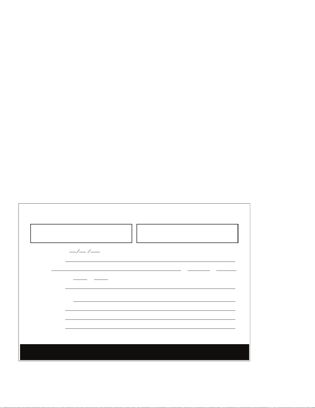
PRODUCT REGISTRATION
Product Registration
BY FAX
COMPLETE THIS FORM AND FAX TO:
(336) 661-1660 in the USA
1-(800) 204-0109 in Canada
PRODUCT REGISTRATION CARD
Model
Date of Installation:
Company Name:
Serial #
Address:
Telephone #: ( ) --Contact:
Installation Company:
Address:
Telephone #:
Contact:
FAILURE TO REGISTER YOUR PRODUCT MAY VOID YOUR WARRANTY
(Street) Province Postal Code
IMPORTANT IMPORTANT
Page 5

Revision History
Revision History
We reserve the right to make changes to this manual without notice and without incurring any
liability by those changes. Equipment owners may request a revised manual, at no charge, by
calling 1 (800) 858-4477 in the USA or by calling 1 (800) 263-5798 in Canada.
Revision Revised Serial Number Revision
Date Pages Effectivity Description
12.7.15 All D151012934 Released first edition
2.4.16 3 D160113175 Revised splash shield instructions
11,12,13 D160113175 Revised signal instructions
3.1.16 D160113179 Removed direct vent instructions
i
Page 6

Limited Warranty
LIMITED WARRANTY
Champion Industries and Moyer Diebel (herein referred to as "The Companies"), 3765 Champion Blvd.,
Winston-Salem, North Carolina 27105, and 2674 N. Service Road, Jordan Station, Ontario, Canada, L0R 1S0,
warrants machines, and parts, as set out below.
Warranty of Machines: The Companies warrant all new machines of its manufacture bearing the name "Champion or
Moyer Diebel" and installed within the United States and Canada to be free from defects in material and workmanship for a
period of one (1) year after the date of installation or fifteen (15) months after the date of shipment by The Companies, whichever occurs first. [See below for special provisions relating to glasswashers.] Warranty registration must be submitted to The
Companies within ten (10) days after installation either online on the Champion Industries website (http://www.championindustries.com, or the Moyer Diebel website (http://www.moyerdiebel.com in the USA or http://www.championindustries.com/
canada in Canada or by the fax form provided at the front of this manual. The Companies will not assume any responsibility
for extra costs for installation in any area where there are jurisdictional problems with local trades or unions.
If a defect in workmanship or material is found to exist within the warranty period, The Companies, at their election, will either
repair or replace the defective part or accept return of the machine for full credit; provided; however, as to glasswashers, The
Companies' obligation with respect to labor associated with any repairs shall end (a) 120 days after shipment, or (b) 90 days
after installation, whichever occurs first. In the event that The Companies elect to repair, the labor and work to be performed in
connection with the warranty shall be done during regular working hours by a Champion or Moyer Diebel authorized service
technician. Defective parts become the property of The Companies. Use of replacement parts not authorized by The Companies will relieve The Companies of all furtherliability in connection with its warranty. In no event will The Companies' warranty
obligation exceed The Companies' charge for the machine. The following are not covered by The Companies' warranty:
a. Lighting of gas pilots or burners.
b. Cleaning of gas lines.
c. Replacement of fuses or resetting of overload breakers.
d. Adjustment of thermostats.
e. Adjustment of clutches.
f. Opening or closing of utility supply valves or switching of electrical supply current.
g. Cleaning of valves, strainers, screens, nozzles, or spray pipes.
h. Performance of regular maintenance and cleaning as outlined in the operator’s guide.
i. Damages resulting from water conditions, accidents, alterations, improper use, abuse,
tampering, improper installation, or failure to follow maintenance and operation procedures.
j. Wear on Pulper cutter blocks, pulse vanes, and auger brush.
Examples of the defects not covered by warranty include, but are not limited to: (1) Damage to the exterior or
interior finish as a result of the above, (2) Use with utility service other than that designated on the rating plate,
(3) Improper connection to utility service, (4) Inadequate or excessive water pressure, (5) Corrosion from
chemicals dispensed in excess of recommended concentrations, (6) Failure of electrical components due to
connection of chemical dispensing equipment installed by others, (7) Leaks or damage resulting from such
leaks caused by the installer, including those at machine table connections or by connection of chemical
dispensing equipment installed by others, (8) Failure to comply with local building codes, (9) Damage
caused by labor dispute.
Warranty of Parts: The Companies warrant all new machine parts produced or authorized by The Companies to be free
from defects in material and workmanship for a period of 90 days from date of invoice. If any defect in material and workmanship is found to exist within the warranty period The Companies will replace the defective part without charge.
DISCLAIMER OF WARRANTIES AND LIMITATIONS OF LIABILITY. THE COMPANIES' WARRANTY IS ONLY TO THE EXTENT
REFLECTED ABOVE. THE COMPANIES' MAKE NO OTHER WARRANTIES, EXPRESS OR IMPLIED, INCLUDING, BUT NOT
LIMITED, TO ANY WARRANTY OF MERCHANTABILITY, OR FITNESS OF PURPOSE. THE COMPANIES SHALL NOT BE LIABLE FOR
INCIDENTAL OR CONSEQUENTIAL DAMAGES. THE REMEDIES SET OUT ABOVE ARE THE EXCLUSIVE REMEDIES FOR ANY
DEFECTS FOUND TO EXIST IN THE COMPANIES' DISHWASHING MACHINES AND THE COMPANIES' PARTS, AND ALL OTHER
REMEDIES ARE EXCLUDED, INCLUDING ANY LIABILITY FOR INCIDENTALS OR CONSEQUENTIAL DAMAGES.
The Companies do not authorize any other person, including persons who deal in Champion or Moyer Diebel dishwashing
machines to change this warranty or create any other obligation in connection with Champion or Moyer Diebel dishwashing
machines.
ii
Page 7

Table of Contents
Table of Contents
Revision History ................................................................................................................ i
Limited Warranty ............................................................................................................. ii
Safety Symbols ................................................................................................................iv
Installation ......................................................................................... 1
Receiving and Placement ............................................................................ 1
Dish Table Connections .............................................................................. 2
Converting from Standard to Corner Operation ............................................. 3
Water Connection ..................................................................................... 5
Standard Hot Water Connection ...................................................... 5
Ventless Heat Recovery (VHR) Cold Water Connection ....................... 6
Drain Connection ...................................................................................... 7
Drain Water Tempering .................................................................. 8
Electrical Connections ................................................................................ 9
Ventilation Connection .............................................................................. 11
Chemical Connections .............................................................................. 12
Operation ......................................................................................... 14
Control Panel Description.......................................................................... 14
Cycle Option .......................................................................................... 14
Set-Up .................................................................................................... 16
Loading Wares ........................................................................................ 17
Wash Cycles ........................................................................................... 18
Rinse Sentry ............................................................................................ 20
Automatic Drain Cycle ............................................................................. 21
Cleaning ............................................................................................22
Wash and Rinse Spray Arms ..................................................................... 22
Wash Tank and Scrap Screens .................................................................. 23
Exterior .................................................................................................. 23
De-lime ................................................................................................... 24
Maintenance .......................................................................................25
Maintenance Schedules ............................................................................ 25
Troubleshooting Chart .............................................................................. 26
Temperature Display Error Codes ............................................................... 27
Timing Charts and Electrical Schematic ...................................................29
Timing Charts .......................................................................................... 29
Electrical Schematic ................................................................................. 31
iii
Page 8

Safety Symbols
Safety Symbols
The following symbols are used throughout this manual to alert the reader to important information.
WARNING:
Warnning statements indicate a condition or practice that can result in personal injury
or possible death.
CAUTION:
Caution statements indicate a condition or practice that can result in damage to the
machine or associated equipment.
DO NOT:
Do not statements indicate that a condition or practice will diminish the effective
operation of the machine.
OKAY:
Okay statements indicate that a condition or practice is correct and should be
followed.
NOTE:
Note statements highlight important information necessary for the operation of the
machine.
iv
Page 9
Receiving and Placement - Installation
34 "
9
/
16
Receiving
Inspect the outside of the shipping carton for signs of damage and report
any damage immediately to a supervisor.
Remove the carton, inspect the dishwasher, and check the inside of the
machine for accessories and installation parts.
Register your machine by fax or online as soon as possible.
CAUTION:
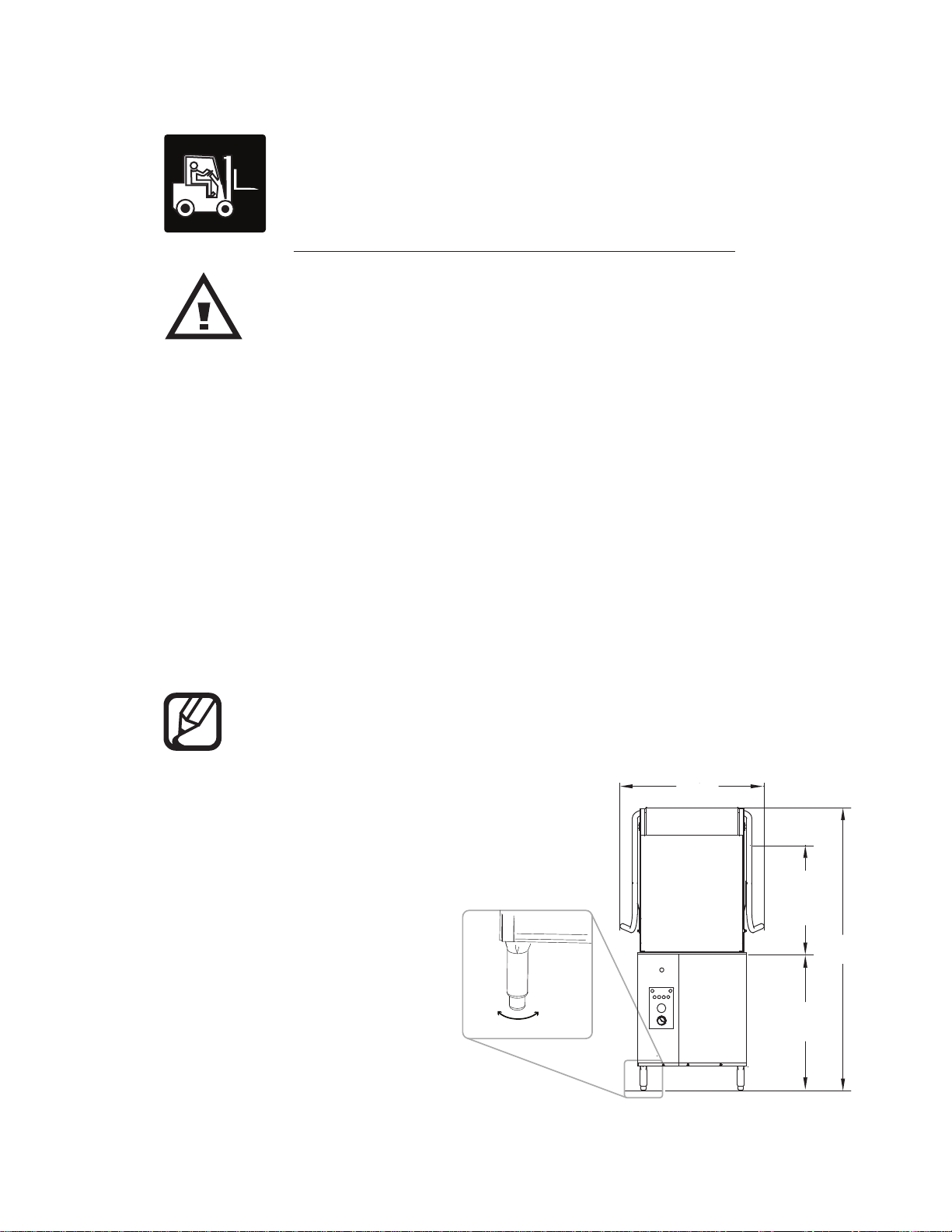
Be careful when lifting and moving the machine to avoid damage.
Placement
Compare the installation site utility connections with the dishwasher utility connections and
make sure they are the same.
For straight-through operation, provide 20" [508mm] clearance out from the front of the
machine and 20" [508mm] out from the left-side of the machine by 27" [686mm] clearance
above the floor for servicing.
For servicing a corner operation machine, provide 35" [889mm] clearance out from the
front of the machine under the right-hand tabling, 35" [889mm] out from the left-hand of the
machine under the left-hand tabling, and 35" [889mm] out from the front of the machine.
Provide 27" [686mm] clearance above the floor on all sides. The dishwasher has 4 adjustable
feet for leveling. Level the dishwasher front-to-back and side-to-side.
NOTE:
Dishwashers are shipped from the factory for straight-through operation but are field
convertible to corner operation.
[878]
27"
LEVEL ADJUSTMENT
[686]
Door
Clearance
33¾"
[857]
71½"
[1816]
Fig. 1
1
Page 10
Installation
1/2”
Dish Table Connections
CAUTION:
Dish tables should be secured to the dishwasher after it is permanently located.
Dish table Dish table
Fig. 2 - Standard straight-through operation.
Refer to Fig. 3 below.
1. Level the dishwasher and dish tables to the required height.
2. Lift up to remove the dishwasher track assembly and set aside.
3. Remove the dishwasher side panels (front and side panel for corner operation).
4. Fit the dish table flanges over the ends of the dishwasher tank and mark two hole locations.
5. Drill 1/4" holes through the table flange and the dishwasher tank.
6. Apply sealant between the table flanges and the wash tank.
7. Install stainless steel 1/4-20 fasteners to secure the tables to the tank.
8. Reinstall the panels and track assembly.
Dish table flange
Drill holes, apply sealant,
& fasten flange to wash tank
Side
panel
Inner wall of
wash tank
Fig. 3 - Dish table flange installation.
2
Page 11
Installation
Converting from Standard to Corner Operation
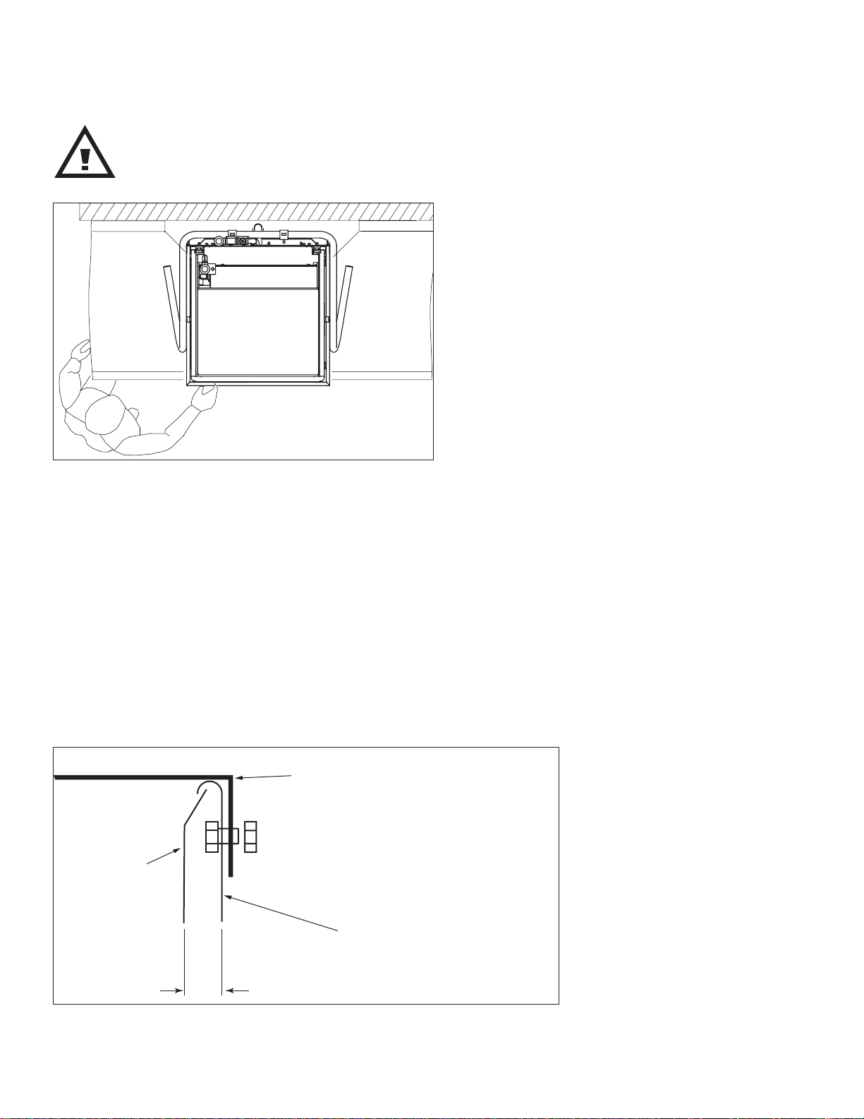
NOTE: An optional splash shield is available for corner operation but may not have
shipped with the machine unless it was specified at the time of order. Contact the
equipment dealer for instructions on how to order the splash shield.
Refer to Fig. 4 and Fig. 5 below to convert the machine:
1. Place the dishwasher so that the control panel is easily accessible.
2. Install the optional splash shield before moving the machine against the wall. The splash shield
may have been installed at the factory or shipped separately. Locate the fasteners supplied at
the rear of the machine, remove and set aside. Place the channel on the bottom of the shield
over the edge of the tank. Reinstall the fasteners and make sure the hood opens smoothly.
3. Connect the utilities before placing the machine in its permanent location.
4. Follow the instructions on the previous page to install the dish tables.
Control
Panel
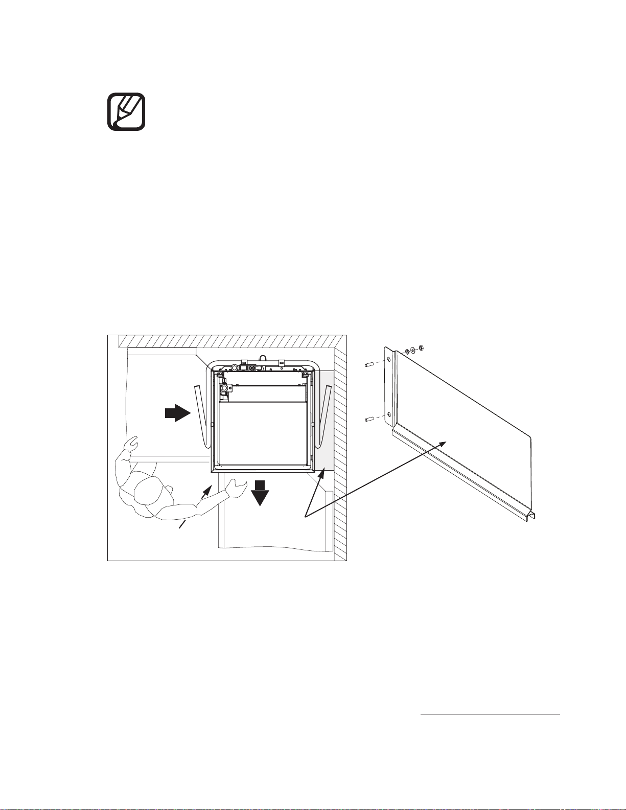
Fig. 4 - Corner configuration.
Splash
Shield
Fig. 5 -
The splash shield fits over the right-hand edge of
the wash tank and fastens to studs on the back
support .
Continued on the next page.
3
Page 12
Installation
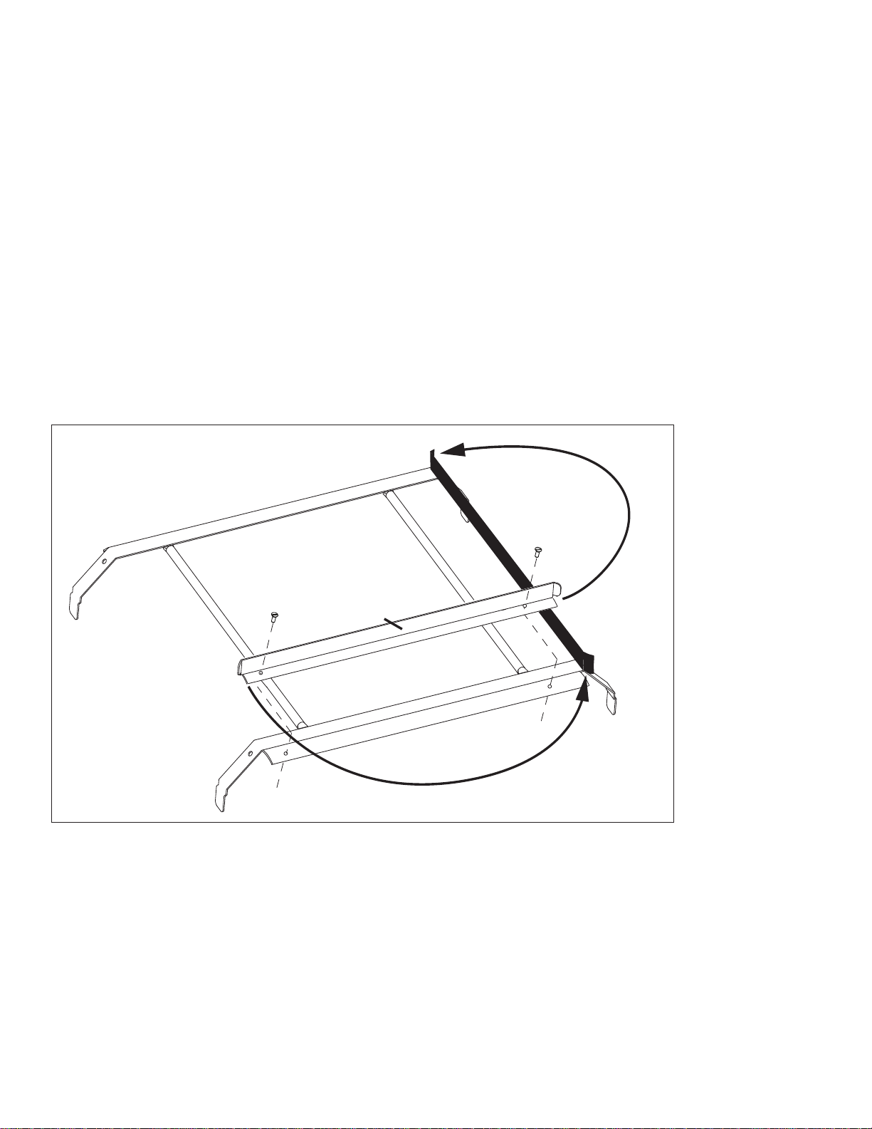
Track Assembly
Guide
Converting from Standard to Corner Operation (continued)
Follow the steps below to convert the track assembly for corner operation:
1. Pull the track assembly straight up and lift it out of the machine, then rotate the track
assembly 180° and reinstall it in the machine.
2. Note the guide attached to the track asssembly. Remove and save the fasteners holding the guide.
3. Position the guide on the right-hand side of the trach assembly and secure with the existing fasteners.
4. Slide a dish rack through the machine to ensure it moves freely.
5. The corner conversion is complete.
FIg. 6 - Move the rear dish rack guide to the right-hand side of the track assembly.
4
Page 13

Water Connection - Standard Model
Installation
HOT
WATER
Connect the plumbing in accordance with the specifications below.
MINIMUM ¾” NPT HOT WATER SUPPLY LINE.
CAUTION: To prevent damage to the dishwasher supply valves, the installing
plumber must thoroughly flush debris from the water supply line before connecting
it to the dishwasher. Damage caused by improper installation is not covered by the
limited warranty.
BOOSTER
RISE ºF
40º
RISE
70º
RISE
MINIMUM INCOMING
TEMPERATURE
140ºF / 60ºC
110ºF / 43ºC
WATER HARDNESS OF 3 GRAINS/US GAL - 0.83 IMP GAL - 5.3mg/L OR LESS. .
INSTALL A ¾” OR LARGER SHUT-OFF VALVE IN THE WATER SUPPLY LINE
AS CLOSE TO THE DISHWASHER AS POSSIBLE FOR SERVICING.
MINIMUM INCOMING
SUPPLY FLOWING PRESSURE
45 PSI / 310 kPa
45 PSI / 310 kPa
MINIMUM/MAXIMUM
OPERATING FLOWING PRESSURE
20/25 PSI / 138/172 kPa
20/25 PSI / 138/172 kPa
CONNECTION IS LOCATED AT REAR LEFT-SIDE OF MACHINE.
Fig. 7 - The incoming HOT water line is a 3/4" NPT connection.
Continued on the next page.
5
Page 14

Installation
Water Connection - Ventless Heat Recovery (VHR) Model
COLD
Connect the plumbing in accordance with the specifications below.
WATER
CAUTION: To prevent damage to the dishwasher supply valves, the installing
plumber must thoroughly flush debris from the water supply line before connecting
it to the dishwasher. Damage caused by improper installation is not covered by the
limited warranty.
BOOSTER
RISE ºF
40-70º
RISE
MINIMUM/MAXIMUM INCOMING
TEMPERATURE
55-75ºF / 13-24ºC
WATER HARDNESS OF 3 GRAINS/US GAL - 0.83 IMP GAL - 5.3mg/L OR LESS. .
INSTALL A ¾” OR LARGER SHUT-OFF VALVE IN THE WATER SUPPLY LINE
AS CLOSE TO THE DISHWASHER AS POSSIBLE FOR SERVICING.
MINIMUM ¾” NPT COLD WATER SUPPLY LINE.
MINIMUM INCOMING
SUPPLY FLOWING PRESSURE
45 PSI / 310 kPa
MINIMUM/MAXIMUM
OPERATING FLOWING PRESSURE
20/25 PSI / 138/172 kPa
NOTE: Local codes may require the installation of a backflow preventer and a pressure
relief tank in the cold water supply line. Consult the local authority for details.
The backflow preventer and pressure relief tank are not supplied by the factory.
Fig. 8 - The COLD water supply is a 3/4" NPT connection
located at the top left-side of the machine.
6
Page 15

Drain Connection - Standard and VHR Models
Connect the drain in accordance with the specifications below.
Installation
DRAIN
GRAVITY DRAIN - 2” OD SLIP-FIT HOSE CONNECTION.
CAUTION: The dishwasher drain connection must comply with all local plumbing,
health and safety codes. Damage caused by improper installation is not covered by
the limited warranty
AUTOMATIC ELECTRIC DRAIN VALVE.
MAXIMUM FLOW RATE: 15 US GPM / 12.5 IMP. GPM / 57 LPM.
NOTE: A Drain Water Tempering Kit Option is available to ensure the temperature of
the water entering the drain does not exceed 140ºF/60ºC ( see next page).
Automatic Electric
Drain Valve
Fig. 10 - The drain is a 2" OD slip-fit hose connection.
7
Page 16

Installation
Water Connection for Drain Water Tempering Valve
Standard and VHR Models
NOTE: The drain water tempering kit is designed to reduce the temperture of
water entering the building drain when the dishwasher is in the automatic drain cycle.
A field installation kit is available from the factory if needed.
Connect the plumbing in accordance with the specifications below.
COLD
WATER
MINIMUM 1/2” NPT COLD WATER SUPPLY LINE.
MAX OPERATING FLOWING PRESSURE IS 45 PSI / 310 kPa.
CONNECTION LOCATED AT REAR OF MACHINE.
CAUTION: To prevent damage to the dishwasher supply valves, the installing
plumber must thoroughly flush debris from the water supply line before connecting
it to the dishwasher. Damage caused by improper installation is not covered by the
limited warranty.
NOTE: A drain water tempering kit is available to install in the field if necessary.
Contact the local authority for information concerning local codes and regulations.
Fig. 9 - The drain water tempering connection is
a 1/2" NPT COLD water connection.
8
Page 17

Installation
Electrical Connection - Single Phase and Three Phase
Standard and VHR Models
The installation of the dishwasher must comply with all local electrical, plumbing,
health, and safety codes or in the absence of local codes, installed in accordance
with the applicable requirements in the National Electrical Code, NFPA 70,
Canadian Electrical Code (CEC), Part 1, CSA C22.1; and the Standard for Ventilation Control and Fire Protection of Commercial Cooking Operations, NFPA 96.
WARNING:
Electrocution may occur when working on energized circuits.
Disconnect power at the main breaker or service disconnect switch,
then lock out and tag it to indicate that work is being performed
on the circuit.
Follow the instructions below and on the next page to connect the electrical power to the machine.
1. A conduit mounting bracket is located at the right rear corner of the machine base as shown
in Fig. 10 below. Position the machine near its permanent location and route the flexible
conduit to the machine making sure to leave a 6 foot / 2 meter service loop.
2. Remove the machine front panel and locate the main terminal block at the right front
corner of the machine. Refer to the Machine Electrical Connection plate mounted directly in
front of the terminal block for electrical specifications. See Fig. 11 below.
3. Route the supply wiring to the main terminal block. A cable clamp is provided to secure the
wiring to the base of the machine. Connection diagrams are located on the next page.
PLAN VIEW
Fig. 10
FRONT VIEW
Continued on the next page.
Machine Electrical Connection
Serial Number: DH5000TModel:
For supply connection, use copper conductors
in accordance with local electrical code, Rated Minimum 90° C (194° F)
Minimum
Supply Conductor Ampacity
Supply Overcurrent Protection Device
Maximum
Overcurrent Protection Device:
Time Delay Fuse or Inverse Time CKT Breaker
Voltage:
Hertz:
0
Phase:
AMPS:
-- AMPS
-- AMPS
3
--
Fig. 11
9
Page 18

Installation
Electrical Connection - Single Phase and Three Phase
Standard and VHR Models (continued)
Refer to the diagrams below for the main terminal block wiring and
three phase and single phase motor connections.
WARNING:
There may be more than one power source connected to the
machine. Make sure all power sources are disconnected, locked
and tagged out before working on the machine.
3 Phase Power Connection
208-240/480V/60/3
L1
L2
L3
Fig. 12
Three Phase Motor
HIGH Voltage Connection
W2 U2 V2
Y/G Y/G
U1 V1 W1
BLK BRN G R AY
L1 L2 L3
L1
LINE IN
L2
L3
GND
Three Phase Motor
LOW Voltage Connection
W2 U2 V2
U1 V1 W1
BLK BRN G R AY
L1
L2
L3
1 Phase Power Connection
208-240V/60/1
L1
L2
NOT
USED
L1
L2
USED
GND
NOT
Fig. 13
Single Phase Motor Wiring
with Run Capacitor
Motor
A
M
T
Thermal
Protector
WHT
BRN
BLK
W1
V1
U1
LINE IN
Cable
GRAY
BRN
BLK
Y/G
CAP
L1
L2
10
Fig. 14
NOTE: CHANGING MOTOR ROTATION -
An arrow on the rear motor housing indicates that the proper motor rotation is
clockwise when viewed from the rear. To change the rotation on three phase machines,
reverse L1 and L2 at the main terminal block.
Page 19

Ventilation - Vent Fan Control for Standard Model Only
Standard model installations using an approved vent hood may require a vent
fan signal. This signal is supplied by the dishwasher control circuit. A qualified
installer must connect a signal circuit to the fuse holder and a common
neutral terminal provided. See Fig. 15.
Installation
CAUTION: To prevent damage to the dishwasher do not connect vent fan motor
to the Line Power 120VAC 1.0 Amp fused connection terminals. Damage to any
component caused by improper installation is not covered by the limited warranty.
The fused 120VAC Line Power is designed to operate an external vent fan contactor
only (supplied by others), and is limited to 1.0 AMP maximum load. The 120VAC
signal is available when the dishwasher power switch is turned ON.
SIGNAL
ONLY
COMMON
NEUTRAL
LINE
POWER
120VAC
1.0 A
MAX.
DETERGENT
120VAC
0.5 AMP
MAX.
RINSE AID
120VAC
0.5 AMP
MAX.
GROUND
120VAC
FACTORY
USE ONLY
GROUND
1.0A
0.5A 0.5A
Fig. 15
11
Page 20

Installation
Detergent Dispenser Connection - Standard and VHR Models
USE A NON-CHLORINATED COMMERCIAL GRADE DETERGENT.
DET
ONLY
SIGNAL
COMMON
NEUTRAL
WASH TANK CAPACITY: 9.5 US GAL / 7.9 IMP. GAL / 36 L
TWO 7/8” DIAMETER HOLES ON LOWER RIGHT SIDE OF TANK.
• TOP HOLE IS FOR DETERGENT INJECTION.
• BOTTOM HOLE IS FOR THE DETERGENT PROBE.
FUSED 120VAC 0.5 AMP MAX. LOAD DETERGENT SIGNAL CONNECTION
AT LOWER FRONT OF MACHINE BEHIND THE FRONT PANEL.
NOTE:
LINE
POWER
120VAC
1.0 A
MAX.
DETERGENT
120VAC
0.5 AMP
MAX.
RINSE AID
120VAC
0.5 AMP
MAX.
GROUND
GROUND
120VAC
FACTORY
USE ONLY
A fused 120VAC 1.0A
Line Power connection is
supplied for chemical
dispensing equipment
if needed.
1.0A
0.5A 0.5A
12
Fig. 16
THE DETERGENT SIGNAL IS ENABLED
THROUGHOUT THE WASH CYCLE.
INJECTION POINT
PROBE
Fig. 17
Page 21

Rinse-Aid Dispenser Connection - Standard Model
STD. RINSE / RACK: .85 US GAL / .7 IMP. GAL / 3.2 L
POT/PAN RINSE / RACK: 1.18 US GAL / .98 IMP. GAL / 4.5L
R /A
1/8” NPT PIPE PLUG AT THE REAR OF THE MACHINE
NEAR THE VACUUM BREAKER FOR RINSE AID INJECTION.
FUSED 120VAC 0.5 AMP MAX. LOAD RINSE AID SIGNAL CONNECTION
• TOP HOLE IS FOR DETERGENT INJECTION.
AT LOWER FRONT OF MACHINE BEHIND THE FRONT PANEL.
• BOTTOM HOLE IS FOR THE DETERGENT PROBE.
Installation
SIGNAL
ONLY
COMMON
NEUTRAL
LINE
POWER
120VAC
1.0 A
MAX.
1.0A
Fig. 18
DETERGENT
120VAC
0.5 AMP
MAX.
RINSE AID
120VAC
0.5 AMP
0.5A 0.5A
Fig. 19
MAX.
NOTE:
A fused 120VAC 1.0A
GROUND
GROUND
120VAC
FACTORY
USE ONLY
Line Power connection
is supplied for chemical
dispensing equipment
if needed.
13
Page 22

Operation
Operation - Control Panel Description
The control panel is located on the front left side of the lower panel. The controls include:
A - ON/OFF green power button. Turns power on and off and initiates a drain cycle
when the switch is placed in the OFF position.
B - CYCLE green indicator light. Illuminates during an automatic timed cycle.
The cycle light is off during the 10 minute automatic drain cycle.
C- CYCLE SELECTION buttons. Four blue push buttons provide 1 minute, and 1.5 minute total cycle
times for normally soiled wares and 4 minute and 6 minute total cycle times for pots, pans and
heavily soiled wares.
D- WASH digital temperature display. Indicates the wash tank water temperature with green LED's
when the wash water temperature is 150°F/66°C.
E- RINSE digital temperature display. Indicates the final rinse water temperature with green LED's
when the final rinse temperature is 180-195°F/ 82-91°C.
F- PRESSURE gauge. Indicates the final rinse water flowing pressure during the final rinse.
The proper pressure reading is 20-22 PSI during the final rinse.
NOTE: The wash cycle time cannot be changed while the dishwasher is washing.
Time Cycle Options
CYCLE OPTION TOTAL CYCLE TIME
Dishwasher Cycle Option 1 Approx. 1 minute
Wash 35 seconds
Rinse 10 seconds
Dwell 15 seconds
Dishwasher Cycle Option 1.5 Approx. 1-1/2 minutes
Wash 65 seconds
Rinse 10 seconds
Dwell 15 seconds
Pot/Pan Cycle Option 4 Approx. 4 minutes
Wash 3-1/2 minutes
Rinse 15 seconds
Dwell 10 seconds
Pot/Pan Cycle Option 6 Approx. 6 minutes
Wash 5-1/2 minutes
Rinse 15 seconds
Dwell 10 seconds
14
Page 23

Control Panel Description
A
CYCLE TIME
1 1.5 46
C
WASH RINSE
Operation
B
D
E
F
PRESSURE
Fig. 21
15
Page 24

Operation
Operation - Set-up
TURN WATER SUPPLY AND MAIN POWER ON.
1
INSTALL PUMP STRAINER AND SCRAP SCREENS (See Fig. 22).
2
INSTALL UPPER AND LOWER WASH AND RINSE SPRAY ARMS.
3
MAKE SURE THEY SPIN FREELY (See Fig. 23).
SCRAP SCREENS X 2
Fig. 22
PUMP STRAINER
WASH SPRAY ARM
16
RINSE SPRAY ARM
Fig. 23
Page 25

Operation - Loading Wares
REMOVE LARGE FOOD PARTICLES AND DEBRIS BEFORE LOADING WARES.
1
LOAD PLATES IN A PEG RACK, BOWLS AND GLASSES IN A FLAT-BOTTOM RACK.
LOAD SILVERWARE IN A SINGLE LAYER IN A FLAT-BOTTOM RACK.
2
LOAD POTS, PANS, AND UTENSILS UPSIDE DOWN IN A FLAT-BOTTOM RACK.
LOAD BAKE SHEETS AND TRAYS ON THE SHORT EDGE IN A BAKE SHEET RACK.
DO NOT OVERLOAD RACKS AND ONLY WASH ONE RACK AT A TIME.
3
NEVER WASH FOREIGN OBJECTS SUCH AS FLOOR MATS, MOPS, OR TOOLS.
4
Operation
CAUTION: Ferrous metals in the form of metal scrub pads must not be used to
clean wares or dishwasher surfaces. Avoid putting any type of ferrous metal
in the machine.
Fig. 24
17
Page 26

Operation
150°F
Operation - Wash Cycles
NOTE: The DH5000T operates as a dishwasher in cycles 1 and 1.5 and as a
pot/pan washer in cycles 4 and 5.
CLOSE THE DOOR. PUSH THE POWER SWITCH ON.
THE POWER SWITCH WILL ILLUMINATE.
1
THE MACHINE WILL FILL WITH WATER AUTOMATICALLY.
CYCLE TIME
1
WAIT APPROXIMATELY 15 MINUTES UNTIL THE WASH TANK
2
DIGITAL DISPLAY INDICATES 150°F/66°C.
15
MINUTES
1.5 4 6
Fig. 25
150
18
WASH
Fig. 26
Page 27

Operation - Wash Cycles (continued)
PRESS A BLUE TIME CYCLE BUTTON. THE BUTTON ILLUMINATES.
3
CLOSE THE DOOR. THE GREEN CYCLE LIGHT ILLUMINATES AND THE WASH
4
CYCLE BEGINS. THE WASH CYCLE IS FOLLOWED BY THE FINAL RINSE.
CYCLE TIME
Operation
1
1.5 4 6
Fig. 27
IF THE DOOR IS OPENED DURING A CYCLE, THE
WASH TIMER WILL RESET AND THE DISHWASHER
WILL RESTART THE CYCLE FROM THE BEGINNING.
19
Page 28

Operation
E
20 PSI
Operation - Wash Cycles (continued)
MONITOR THE FINAL RINSE TEMPERATURE AND PRESSURE DURING THE FINAL RINSE.
7
THE PRESSURE MUST BE A MINIMUM OF 20 PSI AND THE TEMPERATURE MUST BE A
MINIMUM OF 180°F/82°C.
30
20
10
180
PRESSURE
FINAL RINS
180°F
Fig. 28
40
PSI
50
60
0
THE GREEN CYCLE LIGHT WILL GO OUT WHEN THE FINAL RINSE IS COMPLETE. THE
BLUE TIME SELECT BUTTON REMAINS ILLUMINATED.
8
OPEN THE DOOR AND REMOVE THE CLEAN RACK OF WARES. THE MACHINE WILL
REPEAT THE TIME CYCLE UNTIL ANOTHER TIME IS SELECTED.
CAUTION: Wares and dishwasher surfaces are hot during operation.
Be careful when opening the door and loading or unloading dish racks.
Rinse Sentry Feature
The DH5000T is equipped with the rinse sentry feature that continuously monitors the temperature
inside the booster heater to assist in maintaining a final rinse temperature of 180°F/82°C. In the
event that the temperature is below 180°F, Rinse Sentry will add a maximum of 5 minutes to the
selected wash cycle time.
NOTE: Repeated rinse sentry operation may indicate low incoming water
temperature. Check the incoming water temperature if required.
20
Page 29

Operation - Automatic Drain Cycle
The DH5000T is equiped with an automatic electrically operated drain valve.
TO DRAIN THE DISHWASHER:
1
OPEN THE DISHWASHER AND REMOVE ALL WARES FROM INSIDE THE MACHINE.
PUSH THE POWER SWITCH OFF. THE POWER LIGHT WILL GO OUT.
2
NOTE: THE GREEN CYCLE LIGHT IS OFF DURING THE DRAIN CYCLE.
THE DRAIN VALVE WILL OPEN, THE MACHINE WILL DRAIN FOR 10 MINUTES, THE DRAIN
3
VALVE WILL CLOSE AND THE MACHINE WILL POWER OFF.
PUSHING THE POWER SWITCH ON AND IMMEDIATELY OFF WILL START ANOTHER 10
4
MINUTE DRAIN CYCLE AND POWER OFF.
Operation
CYCLE
CYCLE TIME
1
1.5 4 6
Fig. 29
21
Page 30

Cleaning
Cleaning
WARNING:
Dishwasher surfaces can be hot and cleaning chemicals can be caustic to the
skin and eyes. Wear protective clothing and eye protection when handling
chemicals and cleaning the machine.
CLEAN THE MACHINE AT THE END OF EACH MEAL PERIOD OR AFTER EVERY
2 HOURS OF CONTINUOUS OPERATION AND AT THE END OF THE DAY.
To clean the dishwasher:
1. Push the power button OFF, the light will go out, the electric drain valve will open and the
machine will drain. The drain valve will remain open for 10 minutes. Pushing the power
button on and immediately off will open the drain valve for another 10 minutes.
2. Open the door and flush the interior with fresh water.
3. Remove the upper and lower wash and rinse spray arms and flush with clean water.
4. Check the rinse spray arm nozzles. If necessary, remove the end plugs and clean the nozzles
with a small paper clip to remove lime or other debris. Flush the arms clean and replace the
end plugs. See Fig. 30 below.
Rinse Arm Spindle
Paper Clip
End
Plug
Wash Spray arm
22
Fig. 30
Page 31

Cleaning
Cleaning (continued)
5. Remove the scrap screens and pump strainer making sure that debris does not fall out of the
screens and into the wash tank. Flush and backflush the screens in a sink.
Do not strike the screens against hard surfaces.
6. Clean the round drain screen in the bottom of the wash tank. Clean the float switch.
See Fig. 31 below.
SCRAP SCREENS X 2
PUMP STRAINER
DRAIN SCREEN
Fig. 31
7. Rinse and drain the machine. Wipe the interior with a soft cloth. Reinstall the scrap screens
and spray arms making sure the spray arms spin freely.
8. Wipe the exterior clean with a soft cloth and mild detergent.
DO NOT FLUSH THE EXTERIOR OF THE MACHINE WITH WATER.
9. Leave the door open to dry the interior of the machine.
23
Page 32

Cleaning
Cleaning - Deliming
Minerals accumulate on the interior surfaces of the dishwasher. The deposits have a white haze
and, in cases of heavy accumulation, may appear as a granular solid. The generic name for
mineral deposits is lime. The removal of lime deposits is called deliming. The dishwasher should be
delimed regularly.
WARNING:
Death or serious injury may result when deliming solution is mixed with
sodium hypochlorite (chlorine bleach) sanitizing agent. Mixing may cause
hazardous gases to form. Deliming solution and other acids must never be
mixed with chlorine, iodine, bromine, or fluorine.
WARNING:
Deliming solutions can cause severe irritation and possible chemical burns.
Always wear protective clothing and goggles when handling chemicals.
NOTE: Contact a qualified chemical supplier for deliming chemicals and
instructions to delime the dishwasher. Follow all of the chemical supplier's
directions making sure to always wear eye protection, rubber gloves and
rubber aprons when handling chemicals and deliming the machine.
24
Page 33

Maintenance
Daily Maintenance
1. Check all of the wash arm and rinse arm spray jets and clean as necessary.
2. Make sure the water supply is on and the drain is not clogged.
3. Check the temperature displays to ensure they are operating.
4. Make sure the dish racks are in good condition.
5. Check the chemical containers and refill as required.
6. Follow the cleaning procedures on pgs. 22-24.
Weekly Maintenance
1. Perform Steps 1-5 in the Daily Maintenance.
2. Inspect water lines for leaks.
Maintenance
3. Check for water leaks underneath the dishwasher.
4. Make sure the floor drain and/or piping handles the drain water discharge.
5. Make sure the dishwasher is level.
6. Clean accumulated lime deposits from the wash tank heating element.
7. Inspect the scrap screen and replace if damaged.
8. Check the spray arms and replace or repair if damaged.
Yearly Maintenance
Contact your authorized service agent for a preventive maintenance inspection.
Lubrication
There are no lubrication points nor schedules for this dishwasher.
NOTE: Consult the chemical supplier for dispensing system maintenance.
25
Page 34

Maintenance
Troubleshooting
Condition Cause Solution
Dishwasher will not run. Hood not closed.
Main power OFF.
Dishwasher OFF.
Low or no water. Main water supply is off.
PRV setting incorrect.
Line strainer clogged.
Solenoid valve defective.
Chemicals won’t feed into
dishwasher.
Poor wash results. Wares incorrectly loaded in
Chemical supply low.
Pick-up tube clogged.
Supply tubing damaged.
Supply tubing kinked.
dishrack.
Clogged screens.
Clogged spray arms.
Chemical injectors not feeding.
Thermostat defective.
Close Hood completely.
Check breaker on panel.
Turn dishwasher ON.
Open supply valve.
Set to 20-22 PSI flowing.
Contact Service Agent.
Contact Service Agent.
Refill chemical container.
Contact Chemical Supplier.
Contact Chemical Supplier.
Straighten tubing.
Reposition wares or reduce
amount of wares.
Clean screens.
Clean spray arms.
Contact Chemical Supplier.
Contact Service Agent.
Detergent Dispenser defective.
Water temperature low.
Dishwasher stays in wash
cycle.
Dishwasher will not drain. Drain screen clogged.
Condensate Removal
Option Model Steam not
being vented.
Rinse Sentr
mode to allow final rinse water
booster temperature to reach
180°F/82°C.
Drain valve defective.
Building drain clogged.
Incoming cold water temp. is
above 75°F/24°C.
Incoming water pressure is
below 45 PSI flowing presuure
at the dishwasher.
Condensate coil or fan
defective.
y extends wash
Contact Chemical Supplier.
Contact Service Agent.
Contact Ser
cycle runs for longer than 6
minutes.
Clean drain screen.
Contact Service Agent.
Contact Building Maintenance.
Check incoming water
temperature.
Check incoming water pressure.
Contact Service Agent.
vice Agent is wash
26
Page 35

Troubleshooting - Display Error Codes
Indicates the wash thermistor is defective.
Indicates the final rinse thermistor is defective.
Maintenance
Indicates the booster thermistor is defective.
27
Page 36

Blank Page
This Page
Intentionally
Left Blank
28
Page 37

B
114470-9
TIME CYCLE - Tall Hood-type Series - MODE "B"
DRAWING REPRESENTS ONLY THE STRUCTURE OF TIME CYCLES.
FOR MODES OF OPERATION SEE DWG# 114470 SHEETS 10-16
NORMAL CYCLE EXTENDED CYCLE
60 SECONDS TOTAL CYCLE
90 SECONDS TOTAL CYCLE
Time Cycle Chart
WASH
DWELL
RINSE
SANITARY DWELL
0
35
35
45
45
45
60
6010020 4030 50 70 9080 100
10080 90705030 4020010 60
6010020 4030 50 70 9080 100
60
10080 90705030 4020010 60
35 SECONDS
0 SECONDS
10 SECONDS
15 SECONDS
WASH
DWELL
RINSE
SANITARY DWELL
0
64
65
64
6010020 4030 50 70 9080 100
65
80
6010020 4030 50 70 9080 100
9080
10080 90705030 4020010 60
80
10080 90705030 4020010 60
90
64 SECONDS
0 SECONDS
15 SECONDS
10 SECONDS
CYCLE# 1:
60 SECONDS CYCLE CONSISTING OF:
35 SECOND WASH,
0 SECOND DWELL,
10 SECOND RINSE,
15 SECOND SANITARY DWELL.
CYCLE# 2:
90 SECONDS CYCLE CONSISTING OF:
64 SECONDS WASH,
1 SECONDS DWELL,
15 SECONDS RINSE,
10 SECONDS SANITARY DWELL.
CUSTOMER TO SUPPLY RATED VOLTAGE/PHASE/H z,
AS SPECIFIED PER ORDER,TO DISCONNECT SWITCH.
ALL POWER SUPPLIED TO EACH CONNECTION POINT
MUST COMPLY WITH ALL LOCAL ELEC TRIC CODES.
J.MCALLISTER
DATE SHEET
2MAR12
SCALEDR.BY
1
OF
DESCRIPTIONREV.
A
CHANGED RINSE AND DWELL CYCLE TIMES
B
1
CHANGED RINSE AND DWELL CYCLE TIMES
DATE
13AUG12
19SEP12
BY
JAM
JAM
REV. DESCRIPTION
DATE
BY
TIME CYCLES
Tall Hood-type
The Dishwashing Machine Specialists
REV.
B
2929
Page 38

Time Cycle Chart
B
114470-17
Tall Hood-type Series - MODE C - TIME CYCLES 3 AND 4
CYCLE 3
SANITARY DWELL
WASH
DWELL
RINSE
0 10 20
0 10 20
DRAWING REPRESENTS ONLY THE STRUCTURE OF TIME CYCLES 3 AND 4.
FOR CYCLES 1 AND 2 SEE DWG# 114470 SHEET 9
30
40 6050 70 80 90
30
40
3010020 40 50 60 8070 90
6050 70 80 90
100
110 130120 150140 160
100
110 130120 150140 160
110 120 130 150140 160 200170 180 190 220210 230
100
214
215
214
200180170 190 220210 230
215
170 180 190 220210 230
200
230
250240 260 290280 300
240
270
270250240240 260 290280 300
270250240 260
JUMPER SETTINGS:
JB1 = OPEN
JB2 = CLOSED
JB3 = OPEN
330310 320 340300280 290260240 250 270230210 220190180170 200160140 1501301201109080706050402010030 100
320310 330
290280 300 340320310 330
NOTES:
TRIGGERING EVENT:
CYCLE SWITCH IN POSITION 1, 2, 3 OR
4
"CYCLE SWITCH" STATE IS IGNORED
DURING CYCLE, IT IS READ AT BEGINNING
AT THE CYCLE AND PROPER CYCLE TIME
STRUCTURE APPLIED.
INPUTS
SOLID LINE INDICATES SWITCH
CLOSURE
340
OUTPUT
SOLID LINE INDICATES 120VAC
COMING OUT OF THE OUTPUT
TERMINAL
340320310 330
INITIAL STATE:
POWER ON
DOORS OPEN
TANK FULL
CYCLE 4
SANITARY DWELL
WASH
DWELL
RINSE
CYCLE 3
0 10 20
01020
010 20
4 MINUTE CYCLE (240 SECONDS TOTAL)
CONSISTING OF: 214 SECOND WASH,
1 SECOND DWELL,
15 SECOND RINSE,
AND 10 SECOND DWELL.
40 6050 70 80 90
30
40 6050
30
40 6050
30
30010 20 40 6050 70 80 90
70 80 90
70 80 90
100
110 130120 150140 160
110 130120
100
100
110 130120
100
110 130120 150140 160 200180170 190 220210 230
150140 160
150140 160
CYCLE 4
180170 190 220210 230
180170 190
180170 190
6 MINUTE CYCLE (360 SECONDS TOTAL)
200
200
200
CONSISTING OF: 334 SECOND WASH,
1 SECOND DWELL,
15 SECOND RINSE,
AND 10 SECOND DWELL.
220210 230
220210 230
250240 260 290280 300
250240 260
250240 260
270
270
270
270250240 260 290280 300 340320310 330
290280 300
280 300
290
334
320310 330
334
320310 330
310 330
335
335
340
340
340320
350
360350
360350
360350
360
360350
WASH TIMES:
1 MINUTE =
∞
90 SECONDS = 0 Ω
4 MINUTE = 4.7K Ω
6 MINUTE = 15K Ω
CUSTOMER TO SUPPLY RATED VOLTAGE/PHASE/H z,
AS SPECIFIED PER ORDER,TO DISCONNECT SWITCH.
ALL POWER SUPPLIED TO EACH CONNECTION POINT
MUST COMPLY WITH ALL LOCAL ELEC TRIC CODES.
J.MCALLISTER
DATE SHEET
7MAR12
SCALEDR.BY
30
DESCRIPTIONREV.
A
CHANGED RINSE AND DWELL CYCLE TIMES
1
OF
1
DATE
19SEP12
BY
JAM
REV. DESCRIPTION
DATE
BY
TIME CYCLES
Tall Hood-type
The Dishwashing Machine Specialists
REV.
A
Page 39

Tall Hood-type PLC Electrical Schematic
31
Page 40

Blank Page
This Page
Intentionally
Left Blank
32
 Loading...