

Champion MARQUIS 3000 DD, MARQUIS 6500 DD, MARQUIS 4300 DD, MARQUIS 4800 DD, MARQUIS 5500 DD Owner's Manual
OWNER’S MANUAL
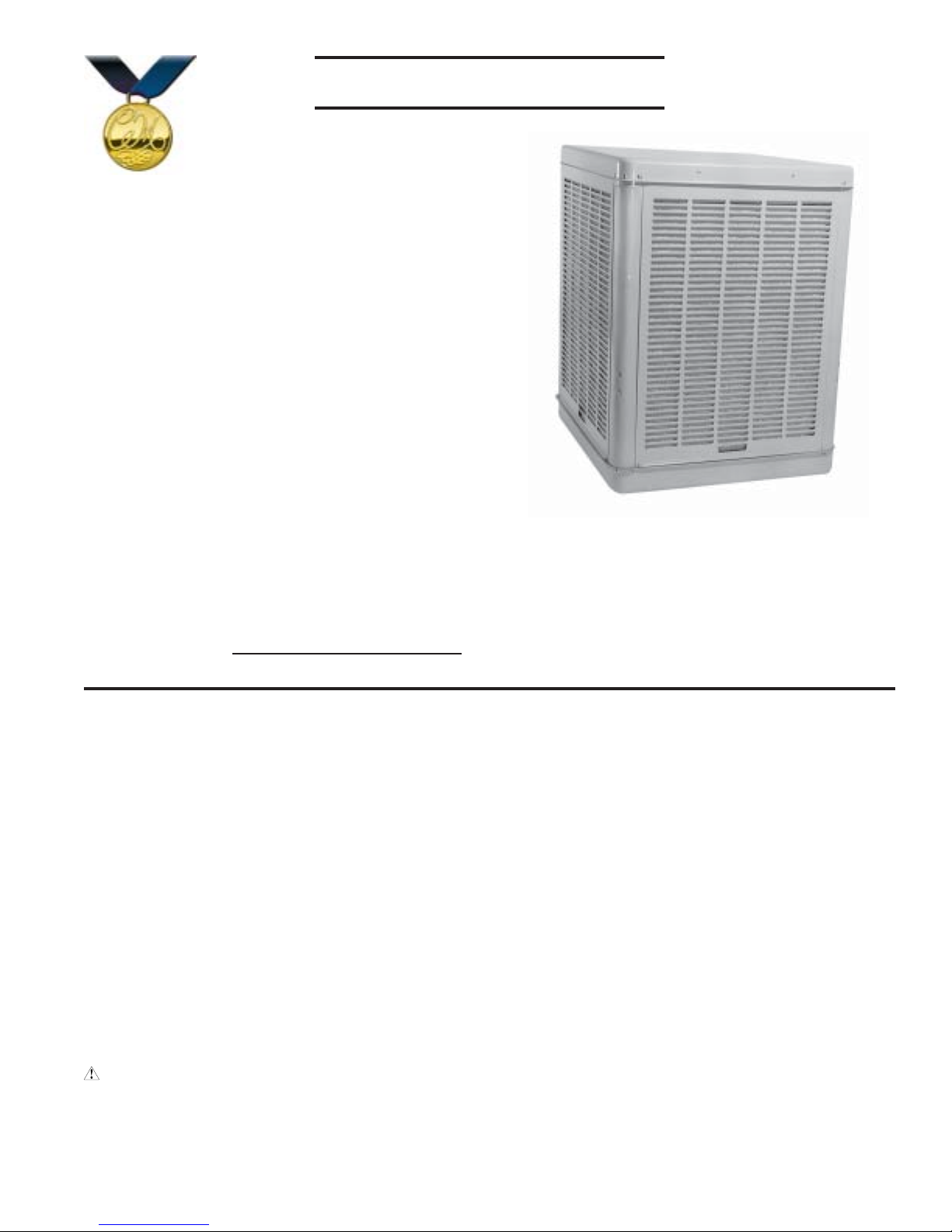
CHAMPION•MARQUIS
EVAPORATIVE COOLER
MODELS
3000 DD
4300 DD
4800 DD
5500 DD
6500 DD
CIRCLE THE MODEL OF YOUR
COOLER AND RECORD THE SERIAL
NUMBER BELOW.
ENCIERRE CON UN CIRCULO EL
MODELO DE SU ENFRIADOR Y ESCRIBE
EL NÚMERO DE SERIE ABAJO.
SERIAL #
NÚMERO DE SERIE
READ AND SAVE THESE INTRUCTIONS
VEA EL ESPAÑOL EN EL INTERIOR.
SAFETY RULES
1. Read instructions carefully.
2. Electrical hook up should be done by a qualified electrician, so that all electrical wiring will conform to your local
standards.
3. Always turn OFF POWER and UNPLUG motor and pump
inside the cooler before installing or performing any maintenance.
4. Your cooler will run on 120 volt A.C., 60 Hz (cycle) current
only.
5. Motor and pump have a grounded, molded plug and an
automatic thermal overload switch which will shut motor off
when it overheats. The motor will restart automatically when
it cools down.
WARNING: To reduce the risk of fire or electric shock,
do not use this fan with any “solid-state fan speed control
device.”
READ CAREFULLY ALL OF THIS
MANUAL BEFORE INSTALLING THE
UNIT
LEA CON CUIDADO TODO ESTE MANUAL
ANTES DE INSTALAR LA UNIDAD
EVAPORATIVE COOLING
Evaporative cooling is nature’s way of cooling. When air is
moved over a wet surface, water is evaporated and heat is
absorbed. When stepping out of a swimming pool with the
wind blowing, evaporative cooling makes you feel cool, even
though the air may be warm. The human body itself is cooled
primarily by the evaporation of perspiration.
This unit works on the same principle. Air is drawn across wet
filter pads where the air is cooled by evaporation and then
circulated throughout the building. It is this combination of
cooled air and the movement of air over the skin which makes
it feel cool.
Unlike refrigeration systems which recirculate the air, an
evaporative cooler continually brings in fresh air while
exhausting old air. You are completely replacing the air every
2 to 4 minutes by opening windows or doors or a combination
of both. The air is always fresh, not stale, laden with smoke
and odors as happens with refrigerated air conditioning.
110503 10-03
www.championcooler.com
OPERATION
To eliminate delivery of hot air when starting your cooler, first
turn the pump on for the first few minutes, then turn on the blower
motor.
These coolers may be used without water for ventilation purposes.
When outside air is cool (for example, at night) or when humidity
is high, the water pump can be turned off.
A cooler can also be installed with a thermostat and attic exhaust
dampers to provide completely automatic operation.
OPEN WINDOWS TO EXHAUST AIR
An often misunderstood concept of evaporative cooling is the
amount of air that should be exhausted. How much should you
open your windows? The fact is that most people do not open
their windows enough. The following two methods will help you
determine the amount to open your windows.
FIRST METHOD
Y ou should allow an opening of at least 2 square feet (288 square
inches) for each 1000 CFM rating of your unit. Example: At
3654 CFM, model 4800 DD requires 7.3 square feet (1052 square
inches) of opening (3654/1000 * 2 = 7.3). Multiply the number of
windows by window width in inches and divide this into the number
of square inches required for your size unit. This will give you
the height to open windows. In this example, four 36 inch wide
windows should be opened 7.3 inches each.
CAUTION: Make sure that the mounting surface is
strong enough to support the operating weight of the
cooler when in use. (For operating weight, see Specification Table.)
CAUTION: Never plug in cooler until installation is com-
plete and unit has been tested for rigidity .
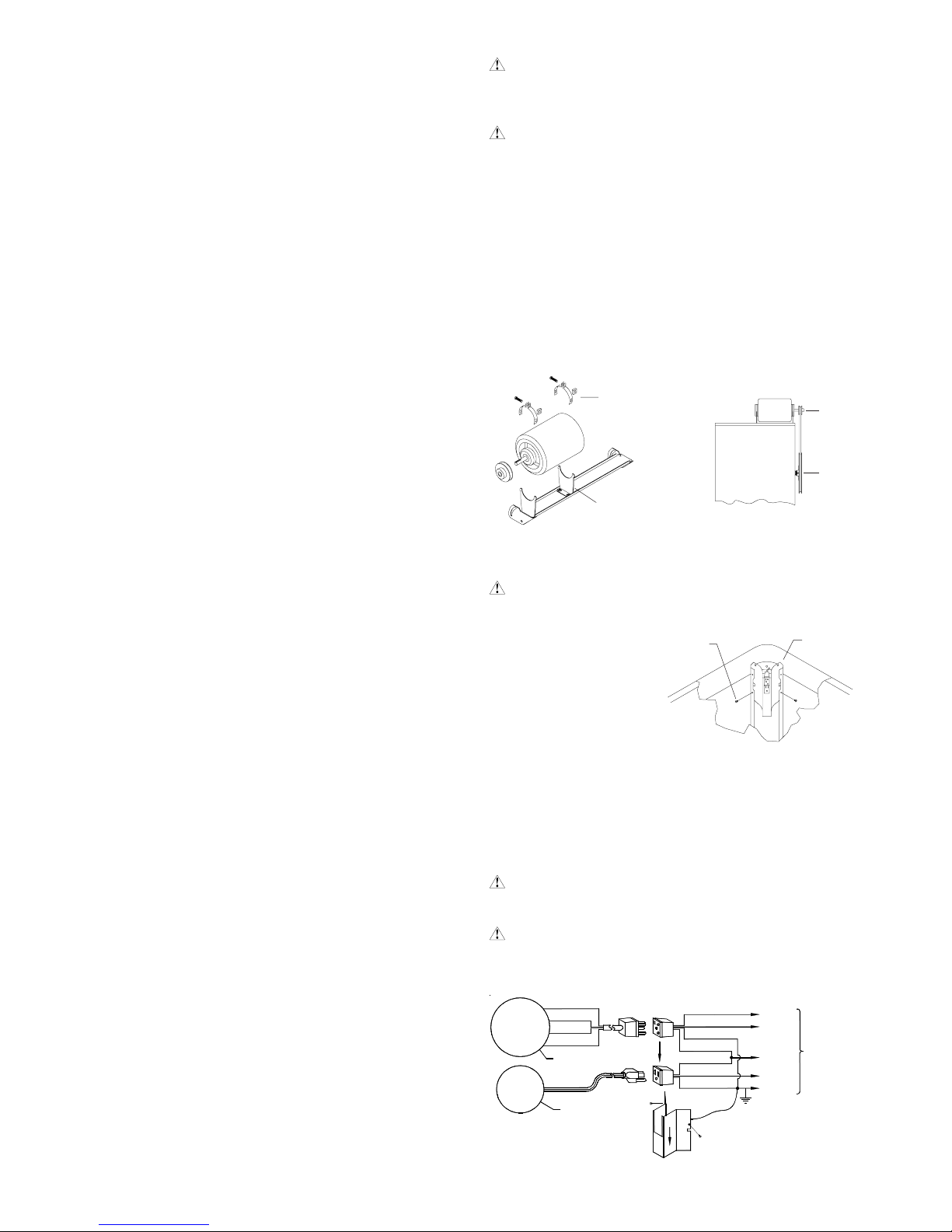
MOTOR INSTALLATION
• Install motor cord. Connect motor cord to motor using the
following color code: Black - Hi, Red - Low, White - Com.,
Green - Ground.
• Mount motor. Install blower motor in the motor mount yokes,
adjusting the yoke if necessary. Fasten with the provided mounting clips (see Fig. 1).
• Install pulley . Install the adjustable motor pulley so that it aligns
with the blower drive pulley (see Fig. 2) and tighten set screw.
MOTOR
FIG. 1
CLIPS
ADJUSTABLE
YOKE
BLOWER
HOUSING
FIG . 2
MOTOR
PULLEY
BLOWER
PULLEY
CHAMPION AIR BALANCING METHOD
1. T ake a piece of tissue paper and cut it lengthwise into 3 equal
strips.
2. Turn your cooler on high cool.
3. Open one window at least six inches wide in each room that
you want to cool.
4. T ake the piece of tissue paper and put it up against the screen
of the open window furthest from the cooler discharge opening. Let go of it. It will do one of three things.
IF It falls down.
THEN CLOSE all of the windows one inch and try step 4 again.
IF It plasters itself to the screen.
THEN OPEN all of the windows one inch and try step 4 again.
IF It stays on the screen lightly .
THEN PERFECT . You are done. Enjoy your cooler .
NOTES:
• When switching to low cool, you must rebalance your home.
Repeat step 4.
• Once you balance your home you can cool some areas more
than others by opening those windows more and closing the
others by the same amount. Repeat step 4 to make sure your
home is still air balanced.
INST ALLATION
NOTE: The pump and float are installed in the cabinet. The
belt, motor pulley, and motor cord are included in the cabinet,
the motor is shipped separately.
ELECTRICAL INST ALLA TION
WARNING: Disconnect all electrical service that will
be used for this unit before you begin the installation.
• Remove junction box.
The electrical junction
SCREWS
box is located in the upper inside corner of the
cooler cabinet. Remove
the two screws and slide
cover down for access to
plug wiring (Fig. 3).
• Hook up electrical. Electrical hook up should be done by a
qualified electrician, so that all electrical wiring will conform to
your local standards. See Fig. 4 for the wiring diagram.
IMPORTANT: When a single speed motor is used, do not use
the red lead on the receptacle and motor plug wiring. T ape of f
end of both of the red leads.
CAUTION: Pump receptacle is for grounded evapora-
tive cooler pump only. Do not plug anything else into
receptacle.
WARNING: Make sure the cooler cabinet is properly
grounded to a suitable ground connection for maximum
safety .
BLACK
HI
LO
GND.
COM.
RED
GREEN
WHITE
BLOWER MOTOR
PUMP MOTOR
BLACK
RED
GREEN
WHITE
WHITE
BLACK/BLUE
GREEN
HI
LO
COM
PUMP
GND
JUNCTION
BOX
FIG . 3
TO
SWITCH
2
FIG. 4
110503
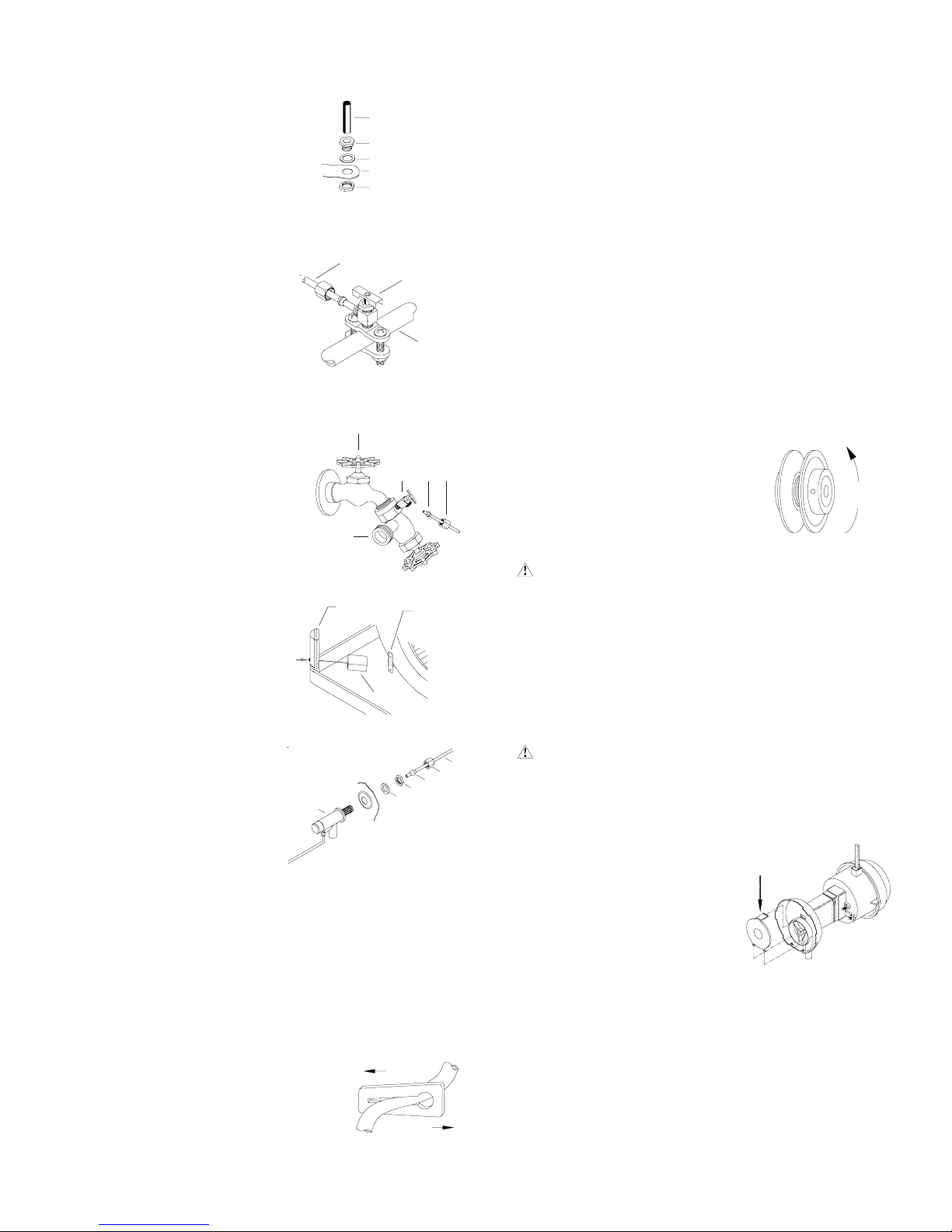
WATER CONNECTION
• Install overflow assembly. Re-
move nut and place nipple through
the hole in the pan, with the rubber washer between the pan and
the head of the drain nipple (Fig.
5). Screw on nut and draw up tight
against bottom of pan. Insert overflow pipe in nipple to retain water.
Overflow pipe may be removed to
drain pan when necessary . A garden hose may be screwed on the
drain nipple to drain water away
from your unit.
• Connect water supply line.
Find the closest supply of water.
Use a saddle valve (Fig. 6) to
connect 1/4” tubing to the cold
water supply or use a Sillcock
and water valve connected to an
outside faucet (Fig. 7). Place the
nut and ferrule on the tubing and
tighten the nut until water tight.
IMPORTANT: Do not connect the
water supply to any soft water
applications. Soft water will
cause corrosion and decrease
the life of the cooler.
SILLCOCK
• Install float and attach water
line to float. The float may be
installed in either the corner
post or bracket (see Fig. 8).
Refer to figure 9 for installation
instructions. Insert the float (1)
thru the hole in the corner post
or bracket. Install the washer
(2) and nut (3). Tighten to
keep the float from turning.
Place the nut (5) and ferrule (4)
on the water supply line. Con-
FIG . 8
nect to float fitting and tighten
until water tight.
• Fill pan. Allow water to fill to
within 1” of top of pan and ad-
1
just float to maintain this water
level. This can be accomplished by bending the float
rod.
• Level water troughs. Operate pump until pads are satu-
rated. Check each trough to see if water is evenly dispersed in
the trough. If they are not, loosen adjustment bolts and level
trough. Retighten bolts. Check to see that all pads are saturated with water and that there are no dry spots or openings in
the pads.
• Adjust water amount. Y our cooler is equipped with a unique
water metering valve (Fig. 10). The amount of water delivered
to the pads may be decreased by pressing the plastic valve as the arrows
indicate. If water is splashing out of water troughs, you may need to decrease
the amount of water delivery. Check to
see that all pads are saturated with water and that there are no dry spots or
openings in the pads.
110503
OVERFLOW PIPE
NIPPLE
RUBBER WASHER
BOTTOM PAN
NUT
FIG. 5
1/4” TUBING
FIG. 6
FAUCET
FIG . 7
CORNER
POST
FLOAT
FIG . 9
SADDLE
VALVE
WATER
SUPPLY VALVE
BRACKET
3
2
INCREASE
DECREASE
FIG . 10
COLD
WATER
PIPE
FERRULE
4
5
NUT
6
AMPERAGE DRAW AND BEL T TENSION
This unit is equipped with an adjustable motor drive sheave for
adjusting the blower wheel speed to the proper loading on different duct systems. It is important that the motor drive pulley is
adjusted to correct size to assure maximum air delivery without
damage to the motor. Be sure to follow these instructions carefully.
• Adjust drive pulley. After the unit is completely installed, adjust the drive pulley to the least diameter and adjust belt tension.
See the maintenance section for adjusting belt tension.
• Start cooler. Install all pad frames, start pump, and allow to
operate until pads are wet.
• Check amperage. With pads wet and unit started, check am-
perage draw with an amperage meter.
• Adjust pulley if necessary. If amperage draw is less than
motor rating, turn off electrical power and remove pad frame.
Unplug motor inside cooler, this will protect you from someone
turning on unit while you are working inside. This should be
done for your safety. Adjust pulley to a larger diameter and
readjust belt tension, plug motor in, install pad frame, and retest amperage
draw. Repeat this process until correct amperage draw is attained.
Increasing motor pulley diameter in-
DECREASE
AMPERAGE
creases amperage draw. Decreasing
motor pulley diameter decreases amperage draw (see Fig. 1 1).
FIG . 1 1
CAUTION: Do not operate cooler with larger amper-
age draw than specified on motor plate.
NOTE: No attempt should be made to completely install this unit
without the aid of an electrician or someone familiar with testing
amperage draw. Failure to comply with these instructions may
void your warranty.
MAINTENANCE
WARNING: Before doing any maintenance be sure
power is off. At the time you remove a pad frame be sure
to unplug motor and pump. This is for your safety .
SPRING ST ART -UP
• Clean pump. Cleaning the
pump is necessary once a
year at start-up. For your
safety, turn unit of f and unplug
motor and pump. Remove the
pump from the mount slot. Remove the base of the pump as
shown in Fig. 12. Clean the
pump and turn the impeller to
ensure free operation. Remove the pump spout and check for any blockage. After
cleaning, reinstall the base onto the pump. Reattach the pump
to the mount in the cooler using the plastic retainer to ensure
that the pump will not overturn. Do not forget to replace the
spout and water delivery tube onto the pump outlet. The pump
has an automatic reset thermal protection.
DEPRESS HERE
TO REMOVE
FIG . 12
3

• Oil bearings. The blower bearings and cooler motor in this
unit should be oiled with a few drops of non-detergent 20/30
weight oil once each year. The motor does not need oil if it has
no oil lines for oiling. Motors that have no lines are lifetime
oiled at the factory and require no further oiling for the life of
the unit.
CAUTION: Do not over oil. Over oiling can cause motor
burn out, due to excessive oil getting into motor winding.
• Change Pads. The pads should be replaced once or twice a
season, depending upon the length of the season. At the beginning and at mid season a clean pad is more absorbent and
efficient and will deliver substantially more
cool air.
• Check belt tension. A 3 lb. force
should deflect the belt 3/4 inches
(see Fig. 13). Readjust belt if
needed.
• Check bleed-off valve to be sure it is not clogged.
3 LB.
3/4 INCHES
FIG . 13
WINTER SHUT DOWN
• Drain water . Always drain all of the water out of the cooler
and water supply line when not in use for prolonged periods,
and particularly at the end of the season. Keep the water line
disconnected from both the unit and water supply so that it
does not freeze.
• Unplug motor and pump. When cooler is not used for extended periods, unplug the motor and pump from inside cooler.
• Cover unit. To protect the life of the finish, a cover for the
unit is suggested in extended periods of non use.
By following the operating, ins tallation, and maintenance suggestions as outlined, you can get many years of efficient and
satisfactory service from your cooler. In the event additional
information is desir ed, your de aler will be more than glad to as sist you in ev ery possible w a y.
LIMITED WARRANTY
This warranty is extended to the original purchaser of an evaporative cooler installed and used under normal conditions. It
does not cover damages incurred through accident, neglect, or abuse by the owner. We do not authorize any person or
representative to assume for us any other or different liability in connection with this product.
T erms And Conditions Of The Warranty
For Eight Years from date of installation, we will replace the original base assembly if water leakage should occur due to rust
out.
For One Y ear from date of installation, we will replace any original component provided by Champion Cooler which fails due to any
defect in material or factory workmanship only.
Exclusions From The Warranty
We are not responsible for replacement of cooler pads. These are disposable components and should be replaced periodically. We are not responsible for any incidental or consequential damage resulting from any malfunction.
We are not responsible for any damage received from the use of water softeners, chemicals, descale material, plastic wrap,
or if a motor of a higher horsepower than what is shown on the serial plate is used in the unit.
We are not responsible for the cost of service calls to diagnose cause of trouble, or labor charge to repair and/or replace parts.
How T o Obtain Service Under This Warranty
Contact the Dealer where you purchased the evaporative cooler. If for any reason you are not satisfied with the response from the
dealer, contact the Customer Service Department: Champion Cooler , 5800 Murray S treet, Little Rock, Arkansas 72209. 1-800643-8341. E-mail: info@championcooler.com.
This limited warranty applies to original purchaser only.
4
110503
 Loading...