

Page 1
For machines beginning with Serial no. 89788
Champion
Champion
Champion
Champion
Technical Manual
Upright Conveyor
Dishwasher
M1
Model
UC-CW
30" Conveyor
Champion
Champion
Champion
Champion
July, 2003
P.O. Box 4149
Winston-Salem, North Carolina 27115-4149
336/661-1556 Fax: 336/661-1660
www.championindustries.com
Machine Serial No.
Manual P/N 113160 Rev. F
2674 N. Service Road
Jordan Station, Ontario, Canada L0R 1S0
905/562-4195 Fax: 905/562-4618
Page 2
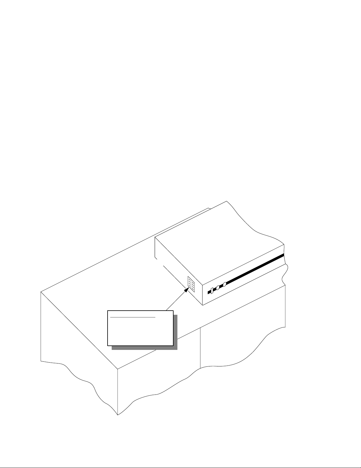
Complete the information below so it will be available for quick reference.
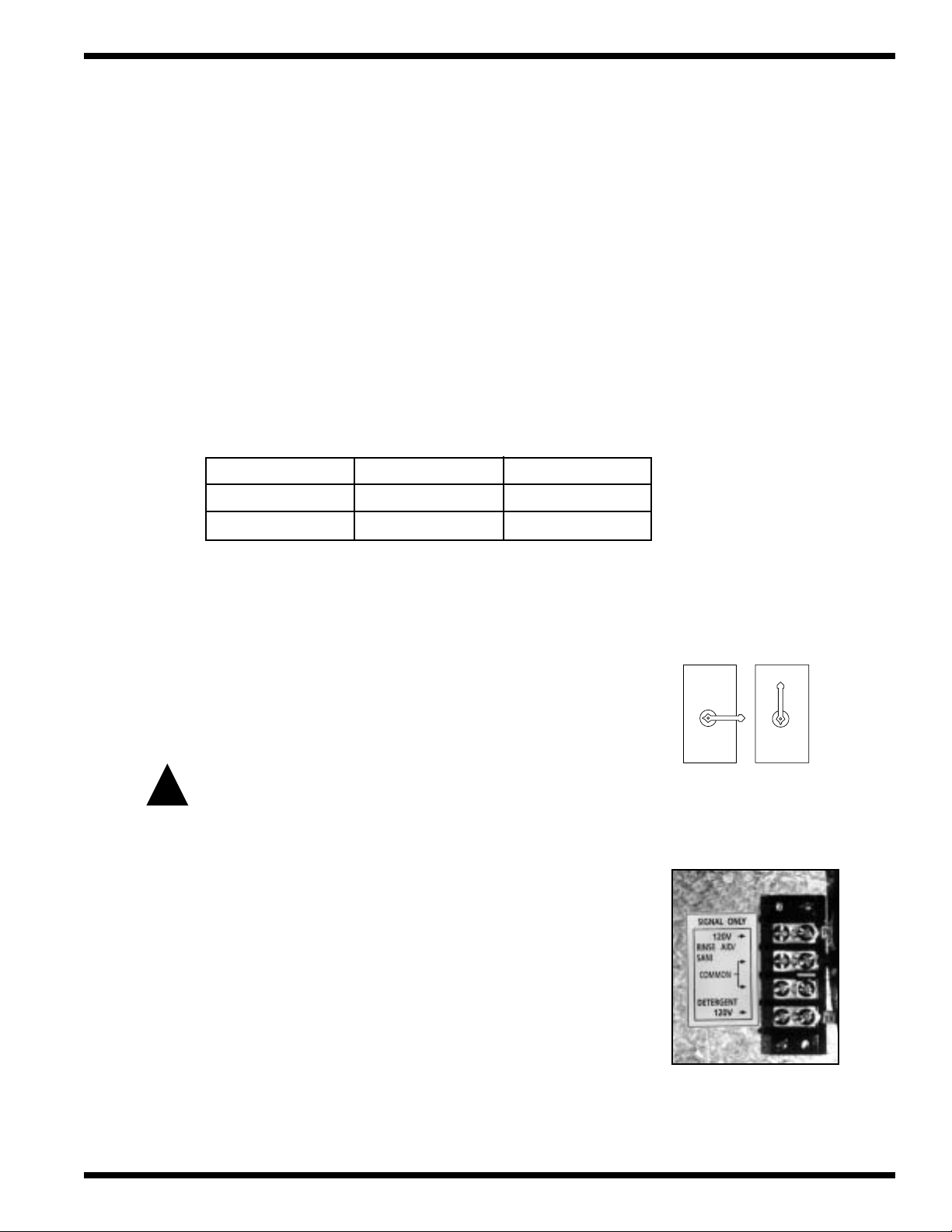
Machine Data Plate with
Model No., Serial No.,
Voltage and Phase is
located on the right or left
side of the Control Cabinet
Top of Machine
Control Cabinet
Left to Right
Model Shown
Model Number __________________________ Serial Number ________________________
Voltage and Phase ______________________________________________________________
Champion Parts Distributor __________________________________ Phone _____________
_____________________________________________________________________________
Champion Service Agency___________________________________ Phone _____________
_____________________________________________________________________________
Champion (USA) Champion (Canada)
National Service Department National Service Department
Phone: 1(800) 858-4477 Phone: 1(800) 263-5798
Fax: 1(336) 661-1660 Fax: 1(905) 562-4618
NOTE: When calling to order parts, be sure to have the model number,
serial number, voltage, and phase of your machine.
COPYRIGHT © 2003 by Champion Industries, Inc.
Page 3

REVISIONS
Revision History
Revision Revised Serial Number Comments
Date Pages Effectivity
03/10/00 All 89788 Reissue of manual and new replacement parts lists.
07/09/01 89 J1436 Added P/N 325838 overflow to Prewash Section.
07/09/01 44 J1436 Added P/N 113291 float switch to Wash and Rinse
Section.
07/09/01 47 — Changed P/N 110854 to 111019 to Econorinse Section.
07/09/01 79 — Added 480V 95KW element to booster.
11/29/01 80
11/29/01 82
11/29/01 84 — Revised bubble numbers on drawings
01/03/02 40, 44, 47 J1534 Change vacuum breaker 1/2" 100500 to 113220
01/03/02 53 J1534 Change vacuum breaker 3/4" 104429 to 113222
01/03/02 79 J1534 Added GC 1/2" solenoid valve 113352
4/30/02 40 Corrected float switch 110854 to 111019
05/22/02 40, 44, 47 Added 900836 Kit*Repair 1/4" & 1/2"
05/22/02 53 Added 900837 Kit*Repair 3/4" Vacuum Breaker
2/5/03 39, 43, 47 Replaced P/N 108391 with 113622 thermometer.
2/5/03 67 Replaced impellers with new part numbers.
2/5/03 93, 97 Replaced Furnace (Siemens) overloads with
7/23/03 40, 44, 47, 53 Revised plastic style vacuum breakers with bronze style.
— Revised bubble numbers on drawing
— Changed P/N 105840 to 105841 on Steam Booster
and repair kit 113392
Vacuum Breaker
Telemecanique (Square D) overloads.
i
Page 4

WARRANTY
LIMITED WARRANTY
Champion Industries Inc. (herein referred to as Champion), P.O. Box 4149, Winston-Salem, North Carolina 27115,
and P.O. Box 301, 2674 N. Service Road, Jordan Station, Canada, L0R 1S0 , warrants machines, and parts, as set out
below.
Warranty of Machines: Champion warrants all new machines of its manufacture bearing the name “Champion” and
installed within the United States and Canada to be free from defects in material and workmanship for a period
of one (1) year after the date of installation or fifteen (15) months after the date of shipment by Champion,
whichever occurs first. [See below for special provisions relating to glasswashers.] The warranty registration
card must be returned to Champion within ten (10) days after installation. If warranty card is not returned to
Champion within such period, the warranty will expire after one year from the date of shipment.
Champion will not assume any responsibility for extra costs for installation in any area where there are
jurisdictional problems with local trades or unions.
If a defect in workmanship or material is found to exist within the warranty period, Champion, at its election,
will either repair or replace the defective machine or accept return of the machine for full credit; provided, however, as to glasswashers, Champion’s obligation with respect to labor associated with any repairs shall end
(a) 120 days after shipment, or (b) 90 days after installation, whichever occurs first. In the event that Champion
elects to repair, the labor and work to be performed in connection with the warranty shall be done during regular
working hours by a Champion authorized service technician. Defective parts become the property of Champion.
Use of replacement parts not authorized by Champion will relieve Champion of all further liability in connection
with its warranty. In no event will Champion’s warranty obligation exceed Champion’s charge for the machine.
The following are not covered by Champion’s warranty:
a. Lighting of gas pilots or burners.
b. Cleaning of gas lines.
c. Replacement of fuses or resetting of overload breakers.
d. Adjustment of thermostats.
e. Adjustment of clutches.
f. Opening or closing of utility supply valves or switching of electrical supply current.
g. Cleaning of valves, strainers, screens, nozzles, or spray pipes.
h. Performance of regular maintenance and cleaning as outlined in operator’s guide.
i. Damages resulting from water conditions, accidents, alterations, improper use, abuse,
tampering, improper installation, or failure to follow maintenance and operation procedures.
j. Wear on Pulper cutter blocks, pulse vanes, and auger brush.
Examples of the defects not covered by warranty include, but are not limited to: (1) Damage to the exterior or
interior finish as a result of the above, (2) Use with utility service other than that designated on the rating plate,
(3) Improper connection to utility service, (4) Inadequate or excessive water pressure, (5) Corrosion from
chemicals dispensed in excess of recommended concentrations, (6) Failure of electrical components due to
connection of chemical dispensing equipment installed by others, (7) Leaks or damage resulting from such
leaks caused by the installer, including those at machine table connections or by connection of chemical
dispensing equipment installed by others, (8) Failure to comply with local building codes, (9) Damage caused by
labor dispute.
Warranty of Parts: Champion warrants all new machine parts produced or authorized by Champion to be free
from defects in material and workmanship for a period of 90 days from date of invoice. If any defect in
material and workmanship is found to exist within the warranty period Champion will replace the defective
part without charge.
DISCLAIMER OF WARRANTIES AND LIMITATIONS OF LIABILITY
IS ONLY TO THE EXTENT REFLECTED ABOVE. CHAMPION MAKES NO OTHER WARRANTIES,
EXPRESS OR IMPLIED, INCLUDING, BUT NOT LIMITED, TO ANY WARRANTY OF
MERCHANTABILITY, OR FITNESS OF PURPOSE. CHAMPION SHALL NOT BE LIABLE FOR
INCIDENTAL OR CONSEQUENTIAL DAMAGES. THE REMEDIES SET OUT ABOVE ARE
THE EXCLUSIVE REMEDIES FOR ANY DEFECTS FOUND TO EXIST IN CHAMPION DISHWASHING
MACHINES AND CHAMPION PARTS, AND ALL OTHER REMEDIES ARE EXCLUDED,
INCLUDING ANY LIABILITY FOR INCIDENTALS OR CONSEQUENTIAL DAMAGES.
. CHAMPION’S WARRANTY
Champion does not authorize any other person, including persons who deal in Champion dishwashing
machines to change this warranty or create any other obligation in connection with Champion Dishwashing Machines.
ii
Page 5

CONTENTS
CONTENTS
Page
WARRANTY ............................................................................................................................. ii
INTRODUCTION...................................................................................................................... 1
GENERAL ................................................................................................................................. 2
Components and Features.................................................................................................... 2
Options................................................................................................................................. 3
Modular Sections (Details and Dimensions)....................................................................... 4
INSTALLATION........................................................................................................................ 5
Unpacking............................................................................................................................ 5
Locating ............................................................................................................................... 5
Assembling the Sections...................................................................................................... 5
Assembling the Conveyor Belt ............................................................................................ 6
Completing the Assembly ................................................................................................... 7
Installing the Optional Blower Dryer (Steam or Electric) .................................................. 7
Plumbing Connections......................................................................................................... 8
Electrical Connections......................................................................................................... 8
Ventilation Connections....................................................................................................... 9
Machine Vent Damper Settings ........................................................................................... 9
Chemical Connections......................................................................................................... 9
INITIAL START UP.................................................................................................................. 10
Baffles.................................................................................................................................. 10
Thermometers ...................................................................................................................... 10
Conveyor Shut-off Shelf ...................................................................................................... 11
Conveyor Belt Drive Clutch Adjustment ............................................................................ 11
Conveyor Belt Alignment .................................................................................................... 11
Energy Sentinel (Idle pump shut-off).................................................................................. 11
OPERATION.............................................................................................................................. 12
Operation Steps.................................................................................................................... 12
Curtain Placement................................................................................................................ 12
MAINTENANCE....................................................................................................................... 15
Maintenance Schedule......................................................................................................... 15
Cleaning............................................................................................................................... 15
Lubrication........................................................................................................................... 16
Operation Checks ................................................................................................................16
Deliming .............................................................................................................................. 17
iii
Page 6

CONTENTS
TROUBLESHOOTING ............................................................................................................. 18
BASIC SERVICE....................................................................................................................... 21
Page
Electrical Service................................................................................................................. 22
Fuse Blocks—120VAC Control Voltage....................................................................... 24
Motor Starter Overloads................................................................................................ 24
Pump Timer and Final Rinse Timer.............................................................................. 25
Electric Eye Energy Sentinel System ........................................................................... 26
Automatic Fill/Low Water Heat Protection .................................................................. 28
Thermostat Locations and Adjustments ....................................................................... 31
Motors ........................................................................................................................... 32
Mechanical Service..............................................................................................................33
Pump Seal Replacement ............................................................................................... 33
Cross Flow Elbow Adjustment ..................................................................................... 34
Solenoid Valve Repair................................................................................................... 34
REPLACEMENT PARTS .......................................................................................................... 35
WIRING DIAGRAMS............................................................................................................... 105
ELECTRICAL SCHEMATICS ................................................................................................. 110
LIST OF FIGURES
Figure 1—Component Locator .................................................................................................. 2
Figure 2—Control Cabinet Chemical Connections ................................................................... 9
Figure 3—Baffle Locations........................................................................................................ 10
Figure 4—Conveyor Belt Drive Clutch ..................................................................................... 11
Figure 5—Conveyor Belt Alignment ......................................................................................... 11
Figure 6—Curtain Placement..................................................................................................... 12
Figure 7—Auto Fill Operation................................................................................................... 12
Figure 8—Fresh Water Make-up ............................................................................................... 14
Figure 9—Fuse Blocks............................................................................................................... 24
Figure 10—Motor Starter Overloads ......................................................................................... 24
Figure 11—Pump Timer and Final Rinse Timer ....................................................................... 25
Figure 12—Electric Eye Location ............................................................................................. 26
Figure 13—Sensor Mounting..................................................................................................... 26
Figure 14—Bypass Switch.........................................................................................................27
Figure 15—Electric Eye Indicator Lights.................................................................................. 27
iv
Figure 16—Dual Float Switch Assembly.................................................................................. 28
Figure 17—Dual Float Troubleshooting Diagram..................................................................... 30
Figure 18—Electric Tank Heat Thermostats ............................................................................. 31
Figure 19—Electric Booster Thermostats ................................................................................. 31
Page 7

CONTENTS
Page
Figure 20—Booster High Limit................................................................................................. 31
Figure 21—Motor Wiring Connections..................................................................................... 32
Figure 22—Pump Seal Replacement ......................................................................................... 33
Figure 23—Cross Flow Elbow................................................................................................... 34
Figure 24—Parker Solenoid Valve............................................................................................. 34
Figure 25—Asco Solenoid Valve............................................................................................... 34
Figure 26—Load Section ........................................................................................................... 36
Figure 27—Prewash Section...................................................................................................... 38
Figure 28—Wash/Rinse Section ................................................................................................ 42
Figure 29—EconoRinse Section (Optional) .............................................................................. 46
Figure 30—EconoRinse Pumped & Final Rinse Spray Arms................................................... 48
Figure 31—Unload Section ....................................................................................................... 52
Figure 32—Drive Shaft Assembly............................................................................................. 54
Figure 33—Conveyor Drive and Shut-off.................................................................................. 56
Figure 34—Baffles and Back Flow Piping................................................................................ 58
Figure 35—Peg Belt................................................................................................................... 60
Figure 36—Peg Belt with Upper Rod........................................................................................ 60
Figure 37—Flat Belt .................................................................................................................. 62
Figure 38—Insulated Tray Belt and (Optional Silverware Belt)............................................... 62
Figure 39—Stainless Steel Peg Belt .......................................................................................... 64
Figure 40—Pump Assembly...................................................................................................... 66
Figure 41—Electric Tank Heat .................................................................................................. 70
Figure 42—Steam Tank Heat..................................................................................................... 74
Figure 43—Steam Coils (Low Pressure/Standard Pressure) ..................................................... 76
Figure 44—Electric Booster ......................................................................................................78
Figure 45—Steam Booster ........................................................................................................80
Figure 46—Steam Booster 40° Rise.......................................................................................... 84
Figure 47—Steam Booster 40° Rise Low Pressure Only.......................................................... 88
Figure 48—Control Cabinet.......................................................................................................92
Figure 49—Blower Dryer (Optional) ........................................................................................ 96
Figure 50—Control Panel, Electric Booster .............................................................................. 98
Figure 51—Wiring Diagram 57KW Electric Booster ............................................................... 110
Figure 52—Wiring Diagram 63KW Electric Booster ............................................................... 111
Figure 53—Wiring Diagram 72KW Electric Booster ............................................................... 112
Figure 54—Wiring Diagram 81KW Electric Booster ............................................................... 113
Figure 55—Wiring Diagram Electric Tank Heat....................................................................... 114
v
Page 8

CONTENTS
B701669—Wiring Diagram (UCCW-2T, Steam/Electric)
B701670—Wiring Diagram (UC-1T, Steam/Electric)
B701512—Wiring Diagram (UCCW-3T, Steam/Electric)
B701559—Wiring Diagram (UCCW-4T-WS, Steam/Electric)
B701399—Wiring Diagram (UC Tank Heat/Electric)
ELECTRICAL SCHEMATICS
(Beginning with Serial Number 89788)
(Beginning with Serial Number 89788)
(Beginning with Serial Number 89788)
(Beginning with Serial Number 89788)
(Beginning with Serial Number 89788)
APPENDIXES
Appendix A—UC-CW EconoRinse Section....................................................................... 103
Appendix B—Door Safety Switch and Magnet Mounting ................................................. 104
Appendix C—Cross Flow Elbow Adjustments...................................................................105
vi
Page 9

INTRODUCTION
INTRODUCTION
Welcome to Champion...
and thank you for allowing us to take care of your dishwashing needs.
This manual covers the basic Upright Conveyor Dishwasher model UC-CW.
Your machine was completely assembled, inspected, and thoroughly tested at our factory. Then
it was disassembled and crated in sections for delivery to your installation site.
The reassembly and installation of your machine is performed by others. However, Champion
can arrange for an Authorized Champion Service Agency to super
installation. Electrical wiring and plumbing services, including final connections to the machine
are supplied by others.
This manual contains:
• Warranty information
• Installation and operation procedures
• Maintenance instructions
• Troubleshooting guide
• Basic service information
• Replacement parts lists
• Wiring diagrams and electrical schematics
vise the reassembly and
Complete and return your warranty registration card immediately after the installation of your
machine.
All information, illustrations and specifications contained in this manual are based upon the
latest product information available at the time of publication. Champion constantly improves
its products and reserves the right to make changes at any time or to change specifications or
design without notice and without incurring obligation.
For your protection, factory authorized parts should always be used for repairs.
Replacement parts may be ordered from your Champion authorized parts distributor or from
your Champion authorized service agency.* When ordering parts, please supply the model
number, serial number, voltage, and phase of your machine.
*Champion can only ship parts to customers by VISA or MasterCard at list price.
1
Page 10
GENERAL
GENERAL
18
7
5
4
6
8
19
10
9
11
12
23
171717
15161
17
13
14
Figure 1
Left to Right Machine
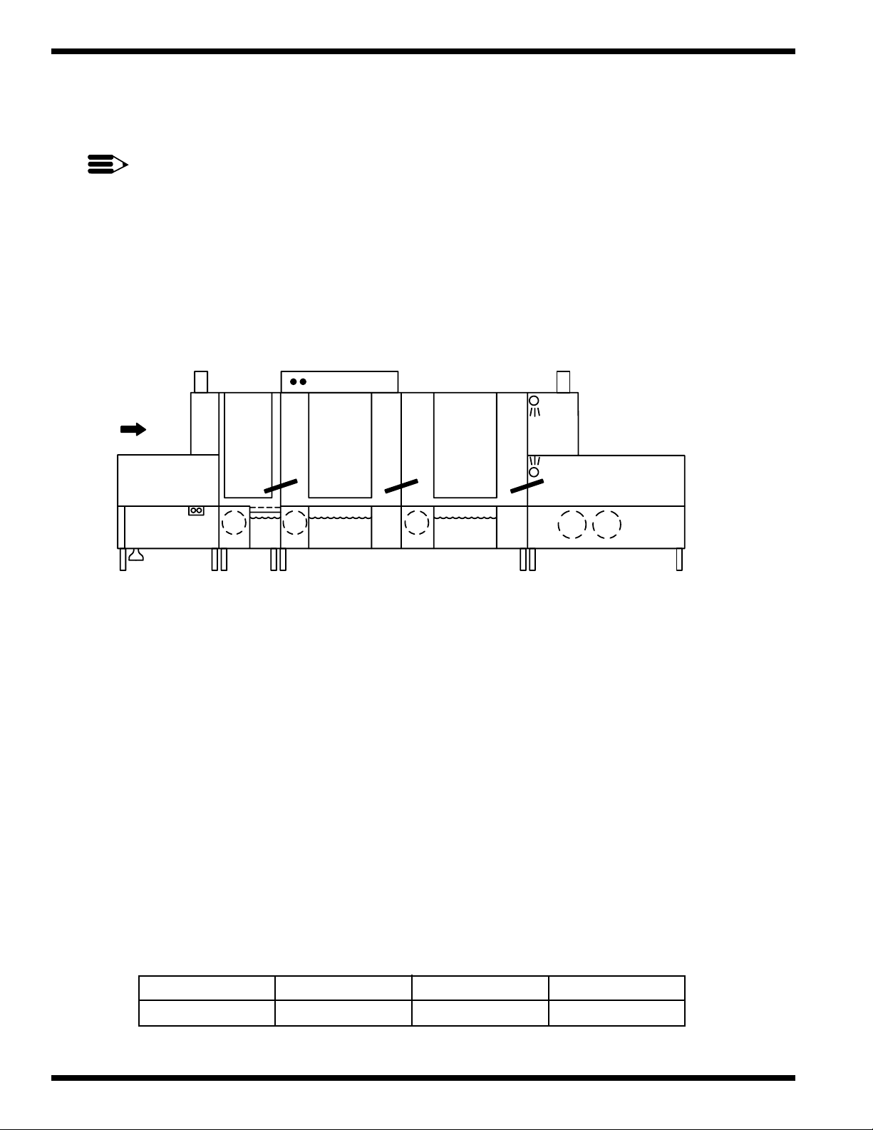
Components and Features
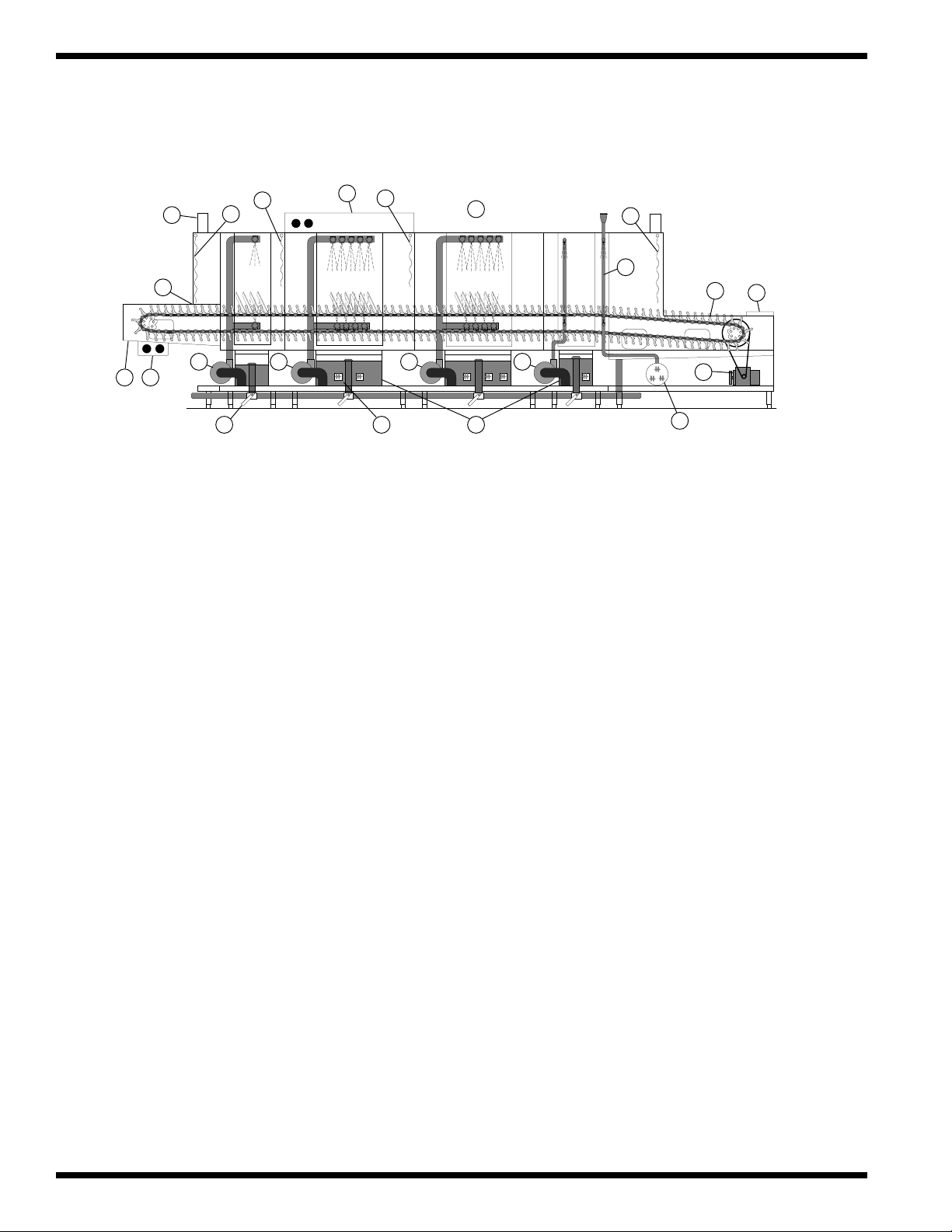
Major Components
The major components of the UC-CW upright conveyor dishwashing machines are listed in
Figure 1.
1. Ball drain valve 11. Peg belt (30" for UC-CW)
2. Load end push button Start-Stop station 12. Sliding conveyor shut-off shelf
3. Load end Recirculating flushing nozzles 13. Conveyor drive assembly
4. Electric Eyes-Energy Sentinel (idle pump shut-off) 14. Optional steam or electric booster
5. Vent openings with 7" stainless steel stacks 15. Steam coil/injectors or electric tank heat
6. Load Section-Long Curtain 16. Low water tank heat protection float switches
7. Prewash Section-Short Curtain 17. High Pressure recirculating pumps
8. Wash Section-Short Curtain 18. Top-mounted control cabinet
9. Unload Section-Long Curtain 19. Automatic Fill
10. Final Rinse Piping
The UC-CW Upright Conveyor is a fully automatic dishwashing machine consisting of modular
sections. Each section is available in a choice of lengths to satisfy your specific space and
warewashing requirements. Champion’s ability to custom build your machine to meet your
application gives you the most powerful and versatile dishwashing machine on the market today.
Standard Features
• All models are constructed of heavy-gauge stainless steel including the panels, base, legs, and feet.
• All Models are available for either Right to Left or Left to Right operation.
• All models are high temperature (180°F final rinse) sanitizing machines.
• All Models have a single common water connection and a single common electrical connection.
(A separate electrical connection is required for an optional electric booster or blower dryer).
• All models have chemical dispensing equipment connection provisions inside the control cabinet.
• Standard Voltages are available in: 208/60/3 240/60/3 460/60/3
For non-standard voltages please consult the factory.
2
Page 11

Options
Your machine may be equipped with one or more of the following options:
• Auto fill with drain interlock
• Stainless steel back panel
• Conveyor Belts
- Flat belt
- Cup belt
- Thermal tray belt
- Silverware belt (with or without riser)
- Belts with upper rods
- or any combination of the above.
• Blower-dryer, steam or electric (Minimum 9 foot unload required)
• Bumper rail, machine mounted
• Cold water thermostat (for prewash section)
GENERAL
• Conveyor, variable speed, electric
• Doors, one piece lift-out for low ceiling installations
• Doors both sides of hood
• Energy sentinel and rinse saver gate switch system
• External scrap bucket on 4 foot prewash (Standard on 2 foot prewash)
• External scrap bucket on 4 foot wash, 6 and 8 foot wash and/or rinse
• Fused disconnect switch for machine and/or booster (unmounted)
• Insulated hoods, insulated panels
• Isolation switches for motors and/or electric tank heat
• Motor pump, 2-HP optional in lieu of 1-HP on 2 foot prewash
• Motor pump, 3-HP optional in lieu of 1-HP on 2 foot prewash
• Side safety rails
• Split unload section for shipping
• Start/Stop station, unload end
• Steam pressure regulating valve (mounted)
• Tray unloader (sample of tray and cart required)
• Water pressure regulating valve (mounted) — Standard with built-in booster
• Champion steam boosters (built-in) Champion electric boosters (built-in)
40°F Rise through 70°F Rise 40°F Rise through 70°F Rise
3
Page 12
GENERAL
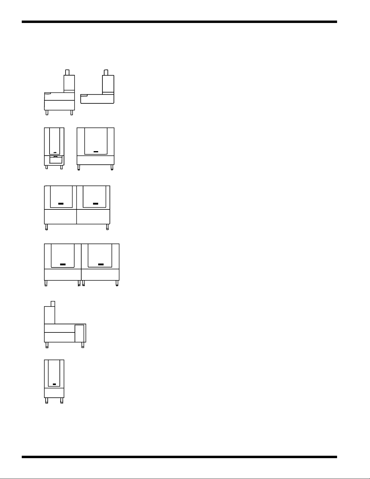
Modular Sections (Details and Dimensions)
A-Load The minimum available length of the load
section is 3 feet and comes in a cantilevered
design. The 4-8 foot load sections come in a
base and leg design.
B-Prewash Prewash sections are available in 2' and 4'
lengths. The 2' section includes a standard
external scrap basket and uses a 1-HP pump
motor. The 4' prewash uses a 3-HP pump
motor. The external scrap basket is optional
on the 4' prewash.
C-Wash/Rinse The C3 module is a 3' section for either wash or
C3/C6
rinse. The C6 is a combination of a 3' wash
section and 3' power rinse section. Both sections
have a 3-HP pump motor. External scrap baskets
are optional.
C-Wash/Rinse The C4 wash or rinse section is a 4' module. The
C4/C8
D-Unload The unload section provides space for handling
E-EconoRinse The EconoRinse section is designed to capture
C8 is a combination of a 4' wash and a 4' power
rinse section. Both sections have a 3-HP pump
motor. The external scrap baskets are optional.
clean ware and is available in a minimum length
of 4'. Longer sections are recommended for
maximum drying or when an optional blower
dryer assembly is used.
and recirculate the final rinse water one
additional time before it is used in the rest of
the machine. The section measures 2' and uses
a 1/4-HP pump motor.
4
Page 13

INSTALLATION
!
INSTALLATION
Unpacking
❑ Immediately after unpacking your machine, check for any possible shipping damage. If
any damage is found, save the packing materials, including the skids, and contact the
carrier immediately.
❑ All the loose parts for your machine and the hardware needed for the assembly of the
sections are contained in a box located on one of the skids.
Locating
❑ Before moving the sections into position, inspect the location site and be sure that the
electrical, plumbing, and ventilation services are provided in the correct locations.
Champion provides a Plumbing and Electrical Connections Drawing, (P&E), detailing
these requirements. Compare the site connections with the machine to ensure that they will
match when the machine is set in its permanent location.
❑ With each section on its skid, place it as close to its permanent position as possible.
CAUTION:
Each section has piping underneath the base. Lift the section carefully to avoid
damaging the piping.
❑ Carefully lift each section, and remove the skid. Remove any tape and shipping brackets.
❑ Remove the wireway covers on the rear of each section and lay the wire bundles
to the outside.
❑ Open all the doors. If you choose to remove the baffles for easier access to the section
ends, be sure to note their location for correct reassembly later. (See Pg. 18, Fig. 3)
❑ Roll the conveyor belt toward the inside of the sections to make the
section assembling easier.
❑ Move the center section (Wash/Rinse) to its final position and thread the feet in
as far as possible.
❑ Move the other sections into position, leaving about 6 inches of separation between them.
Thread all feet in as far as possible. DO NOT BOLT THE SECTIONS TOGETHER AT
THIS TIME.
Assembling the Sections
❑ Check the height of each section and determine which section is the highest
due to floor variations.
❑ Begin with the Wash/Rinse section and adjust its height. Keep in mind that the other
sections will be leveled in relation to this section. Therefore, the height of the wash/rinse
section must compensate for floor height variations.
❑ Level the wash/rinse section side to side and front to back in several places
using a bubble level.
❑ Run a 1/2" bead of silicone sealant on the face of all sides of the hood gasket of the section
end you are going to join.
5
Page 14

INSTALLATION
Assembling the Sections (continued)
❑ Move the next section closer to the prepared end of the center section and adjust the feet of
the second section so that the bolt holes around the hood and gasket align.
❑ Slide the connecting hoses and clamps on the drain pipes and cross-flow pipes.
Do not tighten.
❑ Level the second section side to side and front to back in several places
using a bubble level.
❑ Check the alignment of the conveyor tracks inside the machine, drains,
cross-flows and wireways.
❑ Bolt the HOOD sections together FIRST, using the 5/16-18 X 3/4" bolts, lockwashers and
nuts from the hardware kit.
❑ Bolt the base together NEXT, using the 1/2-13 X 1" bolts, lockwashers, and nuts from the
hardware kit.
❑ Recheck the level of the assembled sections and relevel the second section if necessary.
❑ Adjust the hoses on the drain pipes and cross-flow pipes and tighten the clamps.
❑ Feed the wire bundles through the wireways and connect the wires.
- Match corresponding numbers and connect them together.
- Connect all white and #2 wires together. White and #2 wires are neutral wires.
❑ Connect the copper water lines at the rear of the sections. Be careful not to
cross-thread the connectors.
❑ Connect the steam piping below the base (applicable to steam machines only).
❑ Install the baffles if you removed them prior to connecting the sections.
❑ Repeat the entire process for each section until the machine is completely assembled.
Assembling the Conveyor Belt
❑ Start at the unload end of the machine and pull the conveyor belt around the sprockets until
approximately 1-1/2 feet of belt is exposed on the upper track of the machine.
❑ Pull a section of belt from the next section along the upper track into the unload end.
❑ Join the belt sections together by feeding a conveyor rod through the links, spacers, and
rollers. Install a cotter pin on each end of the rod to secure the assembly.
❑ Continue this procedure until all the conveyor belt sections are joined.
❑ Adjust the conveyor belt tension at the load end by turning the adjusting bolts on the
take-up assemblies. The take-up assemblies are located on either side of the load end
conveyor shaft. Loosen the adjusting bolt locknuts.
❑ Turn each take-up adjusting bolt clockwise equally making sure that the conveyor shaft
remains square with the end of the machine.
❑ Note the slack in the lower portion of the belt and be sure that the adjustment
removes the slack.
❑ Check for the proper belt tension by lifting up the conveyor belt at the unload end. Proper
tension has been reached when the belt can be lifted off the track a maximum of 1-1/2 to 2
inches. Tighten the adjusting bolt locknuts.
❑ RECHECK THE BELT TENSION IN 2-3 WEEKS AND READJUST AS NECESSARY.
(See Initial Start Up #17, Pg. 11)
6
Page 15

INSTALLATION
!
Completing the Assembly
CAUTION:
Overtightening the belt can result in damage to the belt and the conveyor belt drive
assembly.
❑ Trim any excess silicone sealant that may have squeezed out from between the assembled
sections. Apply a finish bead of silicone around the section joints.
❑ Install the vent stacks on the load and unload sections of the machine.
Make sure the damper handles face toward the front of the machine.
❑ Install the curtains. Long curtains hang in hooks on each end of the machine.
Short curtains hang in hooks on the inside of the machine. (See Fig. 6, Pg. 20)
❑ Check each tank and the interior of the machine and remove any foreign material.
❑ Install the screen supports, scrap screens, and access panels.
Installing the Optional Blower Dryer (Steam or Electric)
The blower dryer is available in either electric or steam and is shipped on a separate skid along
with the machine. The vent cowl and mounting hardware for the blower dryer are shipped in the
box containing the dishwashing machine parts and hardware.
❑ Remove the blower dryer from the skid and install the unit on the top of the unload section
of the machine.
❑ Bolt the blower dryer in place using the 5/16-18 X 3/4" bolts, flat washers, and lock
washers from the hardware kit.
❑ Fasten the vent cowl on the discharge end of the blower dryer using the 1/4-20 plain nuts,
flat washers, and lock washers from the hardware kit.
❑ Connect the electrical wiring by moving the prewired flexible conduit into position with
the 3" X 5" junction box located on the side of the blower dryer.
- Secure the conduit to the junction box.
- Match the corresponding wire numbers in the junction box and the conduit and
connect them together.
- Connect all white and #2 wires together. White and #2 wires are neutral wires.
7
Page 16

INSTALLATION
!!!
PLUMBING CONNECTIONS
CAUTION:
Plumbing connections must comply with local sanitary and plumbing codes.
❑ Connect all supply connections for water, steam, and drain lines at the points indicated on
the P&E Connections Drawing.
❑ Tags are wired to the machine piping to indicate these connection points.
❑ Shut-off valves should be installed in all supply lines to allow for servicing of the machine.
❑ Pressure Reducing Valves, supplied by Champion or others, should be installed on the
incoming water supply lines and the incoming steam supply lines as close to the machine
as possible.
❑ Water Hammer Arrestor meeting ASSE-1010 standard or equivalent, should be installed in
the common water supply line at the service connection.
❑ HOT WATER
3/4" NPT 140°F. Flow pressure 20-22 PSI (For machine with built-in 40° rise steam/electric booster)
3/4" NPT 110°F. Flow pressure 20-22 PSI (For machine with built-in 70° rise steam/electric booster)
3/4" NPT 180°F. Flow pressure 20-22 PSI (For machine without built-in booster)
❑ COLD WATER
1/2" NPT 65°F tempering cold water connection. (For prewash with cold water thermostat)
❑ STEAM
Refer to the P&E Connections Drawing or consult the factory.
Blower Dryer- 3/4" NPT @ 85lbs/hr consumption at 15 psi flow pressure.
❑ DRAIN
1-1/2" NPT machine connection 3/4" NPT booster relief to an open drain.
ELECTRICAL CONNECTIONS
WARNING:
Electrical and grounding connections must comply with the National Electrical Code
and/or Local Electrical Codes.
WARNING:
When working on the dishwasher, disconnect the electric service and place a tag at the
disconnect switch to indicate work is being done on that circuit.
❑ A qualified electrician must compare the electrical power supply with the machine
electrical specifications stamped on the MACHINE ELECTRICAL CONNECTION
PLATE located inside the control cabinet before connecting to the incoming service at a
fused disconnect switch.
❑ Motor rotation was set at the factory. Correct rotation for the drive motor is indicated by a
direction arrow decal on the drive sprocket. The sprocket can be found at the unload end of
the machine behind a stainless steel panel.
❑ Correct rotation for the pump motors are clockwise when viewed from the rear of the
pump motor. This is also identified by a direction arrow decal on the pump motor.
❑ Reversing motor rotation must be performed in the Control Cabinet. Reverse the wires L1
and L2 on the disconnect switch side of the main electrical connection terminal block.
8
Page 17
INSTALLATION
!
❑ A knock-out plug is provided at the rear of the control cabinet for
electrical service connections.
❑ Electric boosters and Electric blower dryers each require a separate electric connection.
❑ A fused disconnect switch or circuit breaker (supplied by others) is required to protect each
power supply circuit.
❑ MOTOR STARTER OVERLOAD levers must be checked to ensure they are
in the ON position.
VENTILATION CONNECTIONS
❑ Stainless steel watertight ducting should be installed above the machine.
❑ Duct connections must be made to the inside of the machine vent stacks.
❑ Exhaust air must not be vented into a wall, ceiling, or concealed space of the building.
❑ Machine Ventilation Requirements:
MODEL UC-CW UC-CW-WS
LOAD END 400 CFM at 1/4" S.P. 300 CFM at 1/4" S.P.
UNLOAD END* 900 CFM at 1/4" S.P. 800 CFM at 1/4" S.P.
*With an optional Blower dryer, increase room ventilation by 600 CFM at 1/4" S.P. at the
unload end.
❑ A Minimum of six (6) air changes per hour (provided by building ventilation system) is
recommended for the warewashing area.
MACHINE VENT DAMPER SETTINGS
Minimum
Maximum
❑ Each vent stack is equipped with an adjustable damper.
❑ Proper adjustment of the dampers collects moist vapor as it
exits the machine. This prevents moisture from escaping into
the wash room.
CAUTION:
Damper
Handle
Fig. A
(Closed)
Damper
Handle
Fig. B
(Open)
Opening the dampers too much will remove heat from the
machine interior and may make it difficult to maintain the
proper wash/rinse tank temperatures. Set the dampers to best
meet your particular installation. Figure A and B show the
minimum and maximum vent settings.
CHEMICAL CONNECTIONS
❑ Labeled connection points are provided inside the control cabinet
for chemical dispensing equipment.
These connection points include:
❑ A 120VAC detergent signal between Wire #10 and Common.
❑ A 120VAC rinse aid signal between Wire #12 and Common.
❑ Removable black plugs are located at various points on the
wash tank for the mounting of a conductivity cell.
❑ A removable plug on the final rinse piping is provided as a
Figure 2
Control Cabinet
Chemical Connections
rinse aid injection point.
9
Page 18
INITIAL START-UP
INITIAL START UP
NOTE:
Perform the following checks and adjustments before placing the machine into service.
1. Check the interior of the machine and remove any foreign material.
2. Check the exterior of the machine — make sure that the conveyor belt is free of tape and
foreign material.
Baffles - Tank baffles redirect the flow of water from the spray arm systems back into the
3. Check the baffles — make sure that they are installed and positioned correctly.
tanks. This prevents water loss and keeps the wash, rinse, and final rinse water
in the proper tank.
LEFT TO RIGHT
MODEL
PRE-
WASH
BAFFLE BAFFLE BAFFLE
1 HP 3 HP 3 HP
Figure 3 Baffles
RINSEWASH
FINAL
RINSE
4. Close the tank drain valves along the lower front of the machine.
5. Open the water supply valves. Check for leaks and take corrective action as required.
6. Open the steam supply valves (if applicable). Check for leaks and take corrective
action if required.
- Machine steam valves
- Blower Dryer (if applicable) steam valves
7. Turn the main power on at the breaker panel or fused disconnect switch.
- Machine main power
- Electric booster main power (if applicable)
8. Flip the Power Switch on the front of the Control Cabinet to the “ON” position.
- The Red power on light will illuminate.
- The machine will begin to fill with water.
10
9. Allow the machine to completely fill with water.
- The water will shut off automatically.
10. Check for leaks and take corrective action if required.
11. Monitor the tank thermometers for the proper temperature reading.
- Allow sufficient time for the tank heat to reach operating temperature.
- Refer to the chart below.
TANK Prewash Wash Power Rinse
TEMPERATURE
O
F 120O - 140
O
150O - 170
O
160O - 180
O
Page 19
INITIAL START-UP
12. Move the conveyor shut-off shelf located at the end of the unload section toward the machine.
- This resets the automatic conveyor stop system.
- When an object on the conveyor contacts the shut-off shelf, the conveyor stops.
13. Press the GREEN start button on the front of the control cabinet.
14. Check the direction of rotation of the conveyor belt by observing the direction arrow
decal on the large conveyor drive sprocket. The sprocket is located on the side of
the unload section.
15. If rotation direction is incorrect, reverse wires L1 and L2 on the disconnect switch side of
the main electrical connection terminal block located inside the control cabinet.
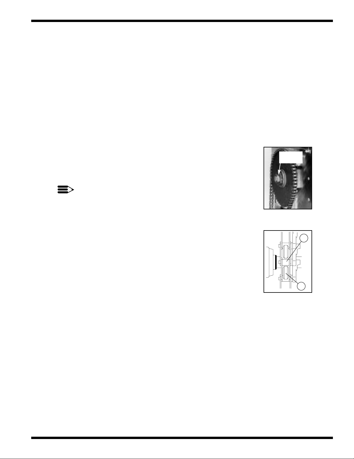
16. Adjust the conveyor belt drive clutch. The clutch is located on the large conveyor drive
sprocket on the side of the unload section. Refer to Fig. 4.
To adjust:
a. Tighten the clutch nut on the center of the drive sprocket until the
conveyor begins to move.
b. Have a person of average build (about 185 lbs.) hold the belt with
Clutch
Nut
both hands and pull against the direction of travel.
c. Continue tightening the clutch nut until maximum effort against the
direction of travel is required to stop the belt.
NOTE:
Final adjustment of the clutch depends upon the overall length of the
conveyor belt and the maximum weight that may be placed on the
conveyor belt during normal operation.
CHECK AND ADJUST CLUTCH MONTHLY.
Figure 4 - Conveyor
Belt Drive Clutch
17. Check the alignment of the conveyor belt. Adjust the take-up
assemblies so that Conveyor Rollers (A) track evenly on Conveyor
Sprockets (B). See Fig. 5.
18. Check the Energy Sentinel (idle pump shut-off) by placing a tray
or dish on the moving conveyor belt.
- The pumps will start as the object enters the tunnel of the machine.
- The optional econorinse pump starts with the final rinse.
-
Check pump motor rotation, CW when viewed from the rear of motor.
19. Check the final rinse temperature as the object enters the
final rinse area.
- The Final rinse temperature must be 180-195°F.
- Adjust the temperature of the incoming water supply if necessary.
Figure 5 - Conveyor
Belt Alignment
- Adjust the booster thermostat setting if necessary.
20. Check the Final rinse water pressure as the object enters the
final rinse area.
- The final rinse pressure must be 20-22 PSI.
- Adjust the Pressure Reducing Valve setting if necessary.
21. Check that the pumps and final rinse shut-off before the object reaches the
conveyor shut-off shelf.
22. Check that the conveyor belt stops when the object pushes the conveyor shut-off shelf.
23. Move the shut-off shelf toward the tunnel of the machine. The conveyor belt will start
moving again.
24. Push the RED stop button. The conveyor belt will stop moving.
A
B
25. Flip the power switch on the control cabinet to OFF. The red power light will go out.
26. Open all the drain valves and check that the house drains can handle the flow.
27. Remove any protective film from the stainless steel and install the side panels and chain guard.
11
Page 20
OPERATION
OPERATION
Operation Steps
Perform the following steps to place your machine in operation. Refer to Fig. 6.
LONG CURTAIN
SHORT CURTAIN
SHORT CURTAIN
LONG CURTAIN
LEFT TO RIGHT
MODEL
PRE-
WASH
1 HP 3 HP 3 HP
Figure 6
Curtain Placement
RINSEWASH
FINAL
RINSE
1. Check the curtains for correct placement in the machine.
- Be sure the short flaps of the Long Curtains face the load end of the machine.
2. Check the spray pipes.
- Be sure the spray pipe gasket is installed on the end of spray pipe before installing.
- Spray pipes are installed by inserting the pipe into the coupler and turning
1/4 turn clockwise.
3. Check the scrap screens.
- Install any scrap basket covers.
4. Check that the conveyor shut-off shelf is pushed toward the machine tunnel.
5. Close the drain valves, located under the base of each tank.
- When the drain handle is horizontal, the valve is open.
- When the valve handle is vertical, the valve is closed
12
6. Check the detergent and rinse aid supplies (supplied by others).
7. Turn on the detergent and rinse-aid dispensers (supplied by others).
8. Close all the doors making sure the door safety switches are activated.
9. Flip the Power Switch on the front of the control cabinet to “ON.”
- The RED power light will illuminate.
- The machine will automatically
fill with water.
- When the tanks are full, the
water will stop and the tank heat
will come on.
10. Fig. 7 illustrates the automatic fill
LEFT TO RIGHT
MODEL
PRE-
WASH
operation.
1 HP 3 HP 3 HP
Figure 7 - Auto-Fill Operation
AUTO FILL 140° F
RINSEWASH
FINAL
RINSE
140° F
Page 21
OPERATION
!
OPERATION (continued)
11. Wait for the tanks to reach operating temperature.
12. Monitor the temperature gauges located below the doors. Refer to the chart below for the
proper temperature readings.
TANK Prewash Wash Power Rinse
O
TEMPERATURE
F 120O - 140
WARNING:
This machine contains moving conveyor parts
- Use caution when working near conveyor.
- Disconnect power to machine when cleaning or servicing.
13. Press the GREEN start button on the front of the control cabinet or the green start button
on the START/STOP station located at the load end of the machine.
O
150O - 170
O
160O - 180
O
- The conveyor belt will begin to move. (Pumps do not run at this time)
- If the conveyor belt does not move, recheck the position of the
conveyor shut-off shelf — and,
- Place the conveyor shut-off shelf in the operating position.
14. Scrap and flush the ware before loading it on the conveyor belt.
For the best washing results:
- Stagger objects across the conveyor belt.
- Cups, glasses, and silverware are best washed in racks. Distribute silverware evenly in
a single layer in the bottom of a flat rack.
As an object enters the tunnel of the load end, it will block the electric eyes. This starts the pumps.
- An Automatic timer controls the pump run time.
- The final rinse, also controlled by an automatic timer, will start as an object moves
near the final rinse area. The optional econorinse pump starts with the final rinse.
15. Check the final rinse temperature as the final rinse begins.
- The temperature gauge is located on the top of the machine in the final rinse piping.
- The correct reading must be between 180°-195°F.
16. Check the final rinse flow pressure during the final rinse.
- The pressure gauge is located on the lower panel of the unload section.
- The correct flow pressure must be between 20-22 PSI. The pressure gauge may read
more than 22 PSI before and after the final rinse cycle. This is a normal condition.
As an object exits the tunnel of the machine the automatic timers will:
- Shut off the final rinse and the pumps before the object reaches the conveyor shut-off shelf.
- If the conveyor belt is loaded with a number of objects, the final rinse and the pumps
will continue to run until an object pushes the conveyor shut-off shelf
into the OFF position.
- The conveyor belt and the final rinse will stop.
- The automatic timers will stop.
13
Page 22
OPERATION
OPERATION (continued)
17. Push the conveyor shut-off shelf towards the tunnel of the machine to return it to its
18. Press the RED stop button on the control cabinet or the START/STOP station
19. Press the GREEN start button on the control cabinet or the START/STOP station on the
operating position. This will:
- Restart the conveyor belt and the final rinse.
- The automatic timers will restart where they left off. This ensures that any objects
remaining on the conveyor belt will be completely washed and sanitized by the
final rinse.
on the load section.
- The conveyor will stop.
- The final rinse will stop.
- The pumps will stop.
load end. The conveyor, the final rinse, and the pumps will start again.
- The machine will continue to run until the automatic timers complete their timed
cycles or an object pushes the conveyor shut-off shelf to the “OFF” position.
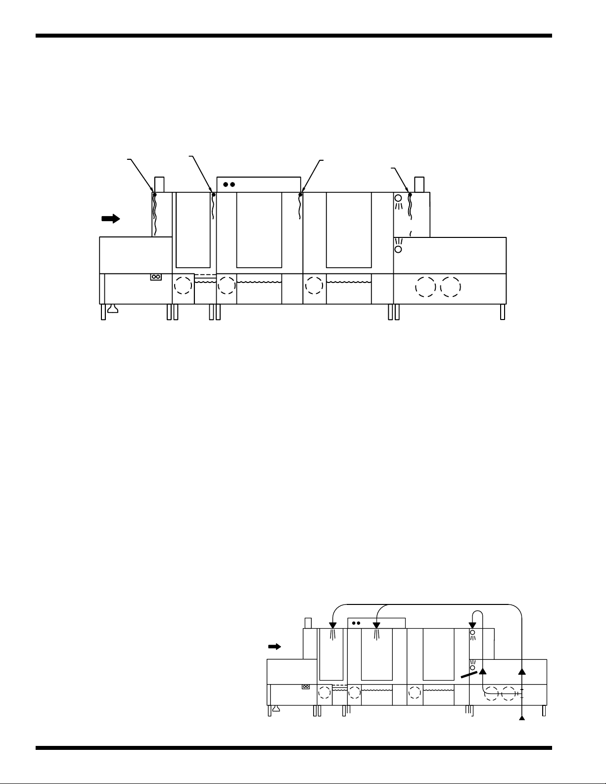
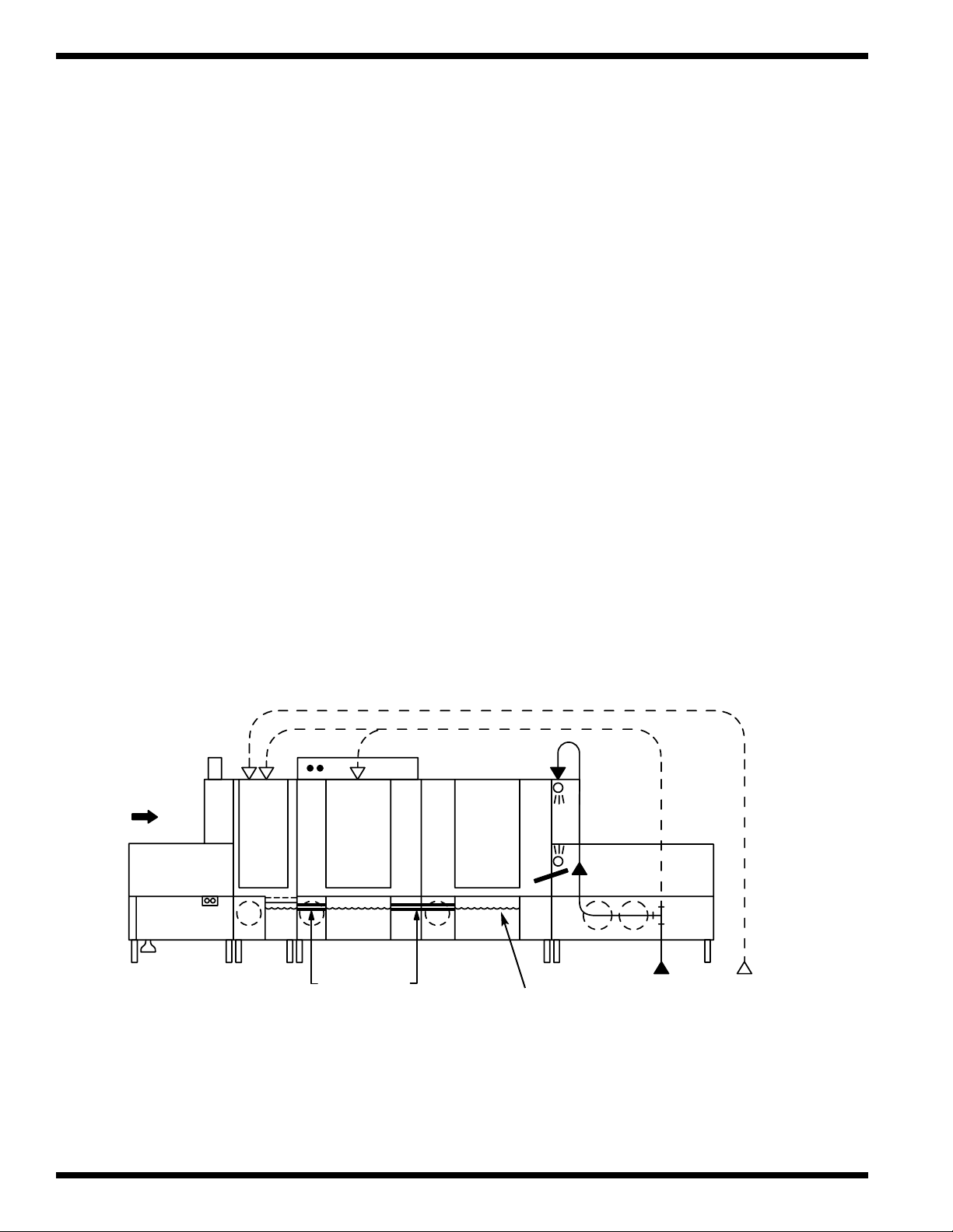
Fresh make-up water is added to the tanks as required automatically.
- A majority of the fresh water comes from the Final Rinse.
- Additional make-up water is supplied by valves activated by float switches located
in each tank.
Refer to Fig. 8 below for the typical fresh water make-up supply.
LEFT TO RIGHT
MODEL
PRE-
WASH
RINSEWASH
FINAL
RINSE
OPTIONAL
1800 F
14
CROSS FLOW
PIPING
Fresh Water Make-up
Figure 8
INDICATES WATER
LEVEL
140° F
INPUT
COLD
WATER
Page 23
MAINTENANCE
MAINTENANCE
Regularly scheduled maintenance will increase the efficiency and life of your machine. A well
maintained machine gives better washing results and service. Undoubtedly, the time that you
invest in daily maintenance now, will pay-off in the future.
Cleaning your machine is the best maintenance that you can provide. Components that are not
regularly flushed and cleaned do not perform well.
The Maintenance Intervals shown in the following schedules are the minimum requirements
necessary for the proper performance of your machine. Shorten the maintenance intervals
whenever your machine is faced with abnormal working conditions, hard water, or
multiple shift operations.
Maintenance Schedule
CLEANING
• Every 2 Hours or After Each Meal Period
1. When the last object on the conveyor belt exits the tunnel of
POWER
ON
OFF
the machine, the pumps will shut off automatically.
2. Press the RED stop button on the control cabinet or the
START/STOP station on the load section.
- The conveyor will stop.
3. Flip the Power switch on the front of the control cabinet to “OFF.”
- The Red power on light will go out.
4. Open the doors.
5. Open the drain valves and allow the machine to drain.
- The valve is open when the handle is placed in the horizontal position.
6. Remove the scrap screens and scrap baskets.
- Back flush the screens and baskets and reinstall in the machine.
- Check spray nozzles.
7. Close the drain valves and doors.
8. Flip the Power Switch on the front of the control cabinet to the “ON” position.
- The RED power light will illuminate.
- The machine will automatically refill with water.
• Every 8 Hours or at the End of the Day
1. Press the RED stop button on the control cabinet or the START/STOP station
on the load section.
2. Flip the Power Switch on the front of the control cabinet to the “OFF” position.
3. Remove all the scrap screens and baskets.
4. Back flush the scrap screens and baskets until clean.
DO NOT STRIKE SCREENS OR BASKETS AGAINST SOLID OBJECTS TO CLEAN.
5. Open the drain valves and allow the tanks to drain.
15
Page 24

MAINTENANCE
!
CLEANING (continued)
CAUTION:
Do Not Leave Water in the Tanks Overnight.
6. Flush the inside of the load and unload sections with clean water.
7. Flush the inside of the tanks with clean water and wipe away any residue.
8. Flush the pump suction strainers, the tank drain screens, and the drain screen
on the unload section.
9. Flush the inside of the machine again making sure all drains are clean and free flowing.
10. Remove the spray pipes by turning 1/4 turn counterclockwise.
- Remove the end cap from each spray pipe
- Flush the pipe and nozzles until clean.
Do not strike the spray pipes on solid objects to clean.
- Replace the end caps
- Make sure that the rubber gaskets are in place on the end of the spray pipe.
11. Reinstall the spray pipes by turning 1/4 turn clockwise.
12. Clean the final rinse pipe nozzles of any mineral deposits.
(A straightened paper clip works very well as a cleaning tool).
13. Remove and clean the curtains. Allow the curtains to air dry.
14. Reassemble the machine.
15. Leave the doors open to allow the interior of the machine to air dry.
16. Clean the exterior of the machine. DO NOT HOSE DOWN WITH WATER.
17. Report any unusual conditions to your supervisor.
Lubrication
• Every 3 months
1. Check the oil level in the conveyor drive gear reducer. Refill with SAE 90 gearcase oil.
2. Add grease to the conveyor shaft bearings; usually one pump from a grease gun using a
general purpose grease.
3. Motor bearings do not require lubrication.
4. Apply a thin coat of grease to the conveyor drive sprocket chain. Avoid getting grease on
the drive clutch; wipe any excess grease off immediately.
Operation Checks
• Daily
1. Check temperature gauges for proper readings.
2. Check pressure gauge for proper reading.
3. Check pumps for leaks around motor shaft.
4. Inspect general condition of machine.
5. Check chemical supplies (supplied by others) and refill as necessary.
16
Page 25
Operation Checks
!
• Weekly
1. Inspect all water lines for leaks and tighten at joints if required.
2. Clean all detergent residue from the exterior of the machine.
3. Check the drains for leaks.
4. Clean accumulated mineral deposits from the tank heating elements
or steam coils.
5. Remove and inspect each spray pipe for blockage and clean if required.
6. Clean the final rinse nozzles of accumulated mineral deposits.
7. Check the float switches located in each tank to ensure they move freely.
8. Inspect the conveyor belt for broken or worn parts.
9. Inspect the electric eyes and clean the lenses.
MAINTENANCE
10. Inspect the conveyor shut-off shelf for freedom of travel.
11. Check the conveyor drive clutch adjustment.
Deliming
Mineral deposits, which are frequently referred to as lime because of their white color,
accumulate in the interior of the machine over time. The amount of lime build-up depends on
the mineral content of your water supply. Machines in regions of the country that have hard
water (high mineral content) will require more frequent deliming than in regions
with soft water (low mineral content).
NOTE:
Consult your chemical supplier for an appropriate deliming solution.
WARNING:
Deliming solutions or other acids must not come in contact with
household bleach (sodium hypochlorite) or any chemicals containing
chlorine, iodine, bromine, or fluorine. Mixing will cause hazardous gases
to form. Skin contact with deliming solutions can cause severe irritation
and possible chemical burns. Consult your chemical supplier for specific
safety precautions.
• Weekly or as required
1. Inspect the interior of the machine for lime deposits.
2. Follow the chemical supplier’s recommendations for the deliming solution.
3. Thoroughly flush the interior of the machine when the deliming is complete.
17
Page 26

TROUBLESHOOTING
TROUBLESHOOTING
On occasion your machine may not operate as expected.
Use the checklist below before you decide that a mechanical or electrical failure has occurred.
Checklist
1. Are the main disconnect switches, breakers, or motor overloads turned ON?
2. Are the main water and steam supplies turned ON?
3. Are the drain valves closed?
4. Are the spray pipes and rinse nozzles clean?
5. Are the spray pipes in the proper locations?
6. Are the pump intakes clean?
7. Are the scrap screens clean and in place?
8. Are the thermostats correctly adjusted?
9. Are the high limit temperature thermostats reset?
10. Are the doors fully closed?
11. Are the conveyor shut-off and drive assemblies in operating condition?
12. Are the chemical supplies adequately filled?
If a problem still exists after verifying the checklist, refer to the following
Troubleshooting Chart.
CONDITION CAUSE SOLUTION
Conveyor will not run Door not closed ................................... Make sure doors are fully closed
Door safety switch faulty .................... Contact your service agency
Start switch faulty ............................... Contact your service agency
Main switch OFF ................................ Check disconnect
Control panel power switch OFF........ Flip switch ON
Conveyor shut-off shelf operated........ Move shelf toward tunnel of machine
Motor overload protector tripped........ Reset overload in control cabinet
Green start button not pressed ............ Press green start button
Conveyor runs but Nothing on the conveyor..................... Load the conveyor
Prewash, Wash, and Electric eyes (Idle pump shut-off) Clean the electric eye lenses
Power Rinse pump system faulty ....................................... Flip the Automatic/Manual switch in the
will not run control cabinet to MANUAL and
Contact your service agency
Optional EconoRinse Final Rinse Timer not calling Refer to EconoRinse section operation
pump will not run for operation ........................................ Appendix A (Page 104)
Motor overload tripped ....................... Reset overload in control cabinet
Defective motor................................... Contact your service agency
18
Page 27

TROUBLESHOOTING
TROUBLESHOOTING
CONDITION CAUSE SOLUTION
A single pump will not run Motor overload tripped ....................... Reset overload in control cabinet
Defective motor................................... Contact your service agency
Low or no water Main water supply is turned off.......... Turn on house water supply
Drain valves are open.......................... Close all drain valves
Doors are not fully closed................... Close doors
Faulty fill valve ................................... Contact your service agency
Stuck or defective float switch............ Free float /Contact service agency
Cross-flow piping misadjusted/
clogged ................................................ Adjust cross-flow setting/Clean piping
Clogged strainer at supply
connection ........................................... Clean strainer screen
PRV misadjusted or defective............. Readjust pressure setting or replace PRV
Continuous water filling Stuck or defective float switch............ Free float/Contact service agency
Fill valve will not close....................... Clean valve,repair or replace valve
Drain valves open................................ Close drain valves
Wash/Power Rinse tank temperature Incoming water temperature at machine Raise incoming temperature
is low when machine is operating is too low............................................. 140°F minimum for 40° rise booster
110°F minimum for 70° rise booster
180° F minimum without booster
Defective thermometer........................ Check or replace
Defective thermostat ........................... Readjust setting or replace
Defective electric heater element........ Check or replace
Low steam pressure or volume ........... Check steam supply pressure
Defective steam trap............................ Check or replace
Defective solenoid valve..................... Check or replace
Prewash tank temperature Incoming cold water temperature Lower incoming water temperature
is too high (Optional Cold too high................................................ to maximum of 65°F
Water thermostat Only) Defective cold water thermostat ......... Check or replace
Insufficient pumped spray Clogged pump intake screen ............... Clean
pressure Clogged spray pipe.............................. Clean
Scrap screen full.................................. Must be kept clean and in place
Low water level in tank ...................... Check drain valves
Pump motor rotation incorrect ............ Reverse wires L1 and L2 in control cabinet
Defective pump seal............................ Contact service agency
Insufficient final rinse or Faulty pressure reducing valve
no final rinse (PRV) .................................................. Clean or replace
Improper setting on PRV .................... Set Flow pressure to 20-22 PSI
Clogged rinse nozzle or pipe .............. Clean
Improper water line size...................... Installer must change to proper size
Clogged “Y” strainer........................... Clean or replace
19
Page 28

TROUBLESHOOTING
TROUBLESHOOTING
CONDITION CAUSE SOLUTION
Low final rinse temperature Low incoming water temperature ....... Raise incoming water temperature
Poor washing results Detergent dispenser not operating ...... Contact the chemical supplier
Poor drying results Excessive humidity in
140°F for 40° rise booster
110°F for 70° rise booster
180°F without booster
Defective thermometer........................ Check or replace
Defective thermostat ........................... Recalibrate or replace
High limit thermostat tripped.............. Reset or replace
Low steam pressure............................. Check steam supply pressure
Detergent supplied not strong
enough ................................................. Contact the chemical supplier
Wash water temperature too low See Condition “Wash/Rinse tank
............................................................. water temperature too low”
Spray pipes clogged ............................ Clean
Improperly scrapped dishes ................ Check scrapping procedures
Ware improperly loaded on
conveyor.............................................. Stagger ware on belt
Maintenance not performed
as required ........................................... See Maintenance Schedule
Electric elements/steam coils have ..... Clean and delime
lime build-up ....................................... Contact the chemical supplier
warewashing area ................................ Check vent dampers and exhaust fans
Improperly stacked dishes
after washing ....................................... Check unloading procedures
Insufficient rinse-aid ........................... Contact chemical supplier
Final rinse temperature See Condition “Final Rinse temperature
too low ................................................ too low”
20
Page 29
BASIC SERVICE
!
!
BASIC SERVICE
To the Reader—
This section is intended for qualified service and maintenance personnel only.
DO NOT ATTEMPT ADJUSTMENTS OR REPAIRS IF YOU ARE NOT QUALIFIED.
A qualified servicer is someone who has:
1. A thorough knowledge of all safety precautions and procedures.
2. A thorough knowledge of basic electricity and electrical troubleshooting methods.
3. A thorough knowledge of dishwashing machine mechanics and operation.
WARNING:
Serious personal injury may result
if persons lacking the proper training or experience attempt to adjust or
repair a Champion Dishwashing Machine.
—In addition—
Serious or permanent damage to the machine may result
if persons lacking the proper training or experience attempt to adjust or
repair a Champion Dishwashing Machine.
WARNING:
This machine contains moving conveyor parts
- Use caution when working near conveyor.
- Disconnect power to machine when cleaning or servicing.
To the Qualified Servicer—
The following service information explains procedures for adjusting and repairing some of the
major components on the UC-CW dishwashers. In addition, you will find some basic guidelines
for troubleshooting and evaluating problems.
Champion dishwashers contain some unique design features that may be unfamiliar to you. We
have included explanations about a number of these features.
This Basic Service section does not cover all possible repair procedures. However, if you require
additional service support, you can call:
Champion National Service
1-800-858-4477
Please have the Model and Serial Number of the machine ready when you call.
21
Page 30

ELECTRICAL SERVICE
Note:
Champion offers a variety of options for the Upright Conveyor dishwasher.
It is extremely important that you identify the options installed on the machine BEFORE you
begin repairs.
The basic operation of the upright conveyor is the same for all models. If you are not completely
familiar with the design and operation of your machine, please read all the information
contained in this manual before attempting any repairs. What appears to be a serious problem at
first, may be corrected with a simple maintenance or operation check.
ELECTRICAL SERVICE
Power Requirements: All models require 3 Phase power.
Service Connections: The main power connection is made at a single point in the Control
Standard voltages are available in 208/60/3 240/60/3 460/60/3
Non-standard voltages are available—Consult the factory.
Cabinet. Optional Electric Boosters have a separate service connection.
Optional Electric Blower dryers have a separate service connection.
Line Voltage: Three phase line voltage
is supplied to: Pump motors
Single phase line voltage
is supplied to: Control Transformer — (In control cabinet)
Control Voltage: 120VAC is supplied by
the secondary of the
control transformer to: Control cabinet switches
Drive Motor
Optional Blower Dryer motor
Electric tank heater elements
Optional Booster tank heater elements
[Step-down Line Voltage: 120VAC]
Remote pushbutton stations
The Electric Eye circuit input
Pump & Final Rinse Timers
Solenoid Valves
Thermostats
Contactors
Motor starter overloads
Hold-in Relay
24VAC Control Transformer
[Step-down 120VAC:24VAC]
22
Page 31

ELECTRICAL SERVICE
!
!
Electrical Service (Continued)
Control Voltage
(24VAC) 24VAC control voltage
is supplied to: Door Safety Switches
Float switches
Conveyor switch
Control Relays (See Control Cabinet/Schematic)
Troubleshooting
Schematics
Champion places an electrical schematic in the control cabinet of every machine before it is
shipped. Schematics are included at the back of this manual as well. Be aware that these
schematics include options that may not apply to your machine. Options are enclosed in dashed
lines with the words (IF USED) next to them on the schematic. Disregard any options that
appear on the schematics which are not a part of your machine.
Tools
All electrical repairs can be made with: Standard set of hand tools
Volt/Ohm Meter (VOM)
Clip-on AC current tester
Circuit Tests
Use a clip-on AC current tester to check the 3-phase motors and electric heaters.
Use a VOM to test the 120VAC and the 24VAC control circuits and their
associated components.
NOTE:
Do not use chassis ground when performing voltage checks.
Doing so will result in false and inaccurate readings.
PERFORM VOLTAGE CHECKS BY READING FROM THE HOT SIDE OF THE
120VAC LINE AND ANY WHITE WIRE. (Wire #2 on the electrical schematic).
WARNING:
USE EXTREME CAUTION when performing tests on energized circuits.
WARNING:
When repairing a circuit, disconnect the power at the main service disconnect switch and
place a tag at the disconnect switch to indicate that work is being performed on the circuit.
23
Page 32

ELECTRICAL SERVICE
ELECTRICAL SERVICE (Continued)
Repairs
Fuse Blocks—120VAC Control Voltage
Two fuse blocks, located in the center rear of the main control cabinet
protect the main control transformer. Each fuse block holds a 5 AMP
fuse. The fuses are marked 1FU and 2FU on the electrical schematic.
To Replace the fuse:
—Disconnect power to the machine at the main service switch.
—Flip the tab on the top of the fuse block to open the block.
—Remove the 5 AMP fuse and replace with another 5 AMP fuse.
—Close the fuse block and turn the main power on.
—If the fuse blows again, DO NOT INCREASE THE FUSE SIZE.
—DETERMINE THE CAUSE OF THE OVERLOAD.
Fig. 9 shows the fuse block opened and the fuse exposed.
Figure 9
Fuse Blocks
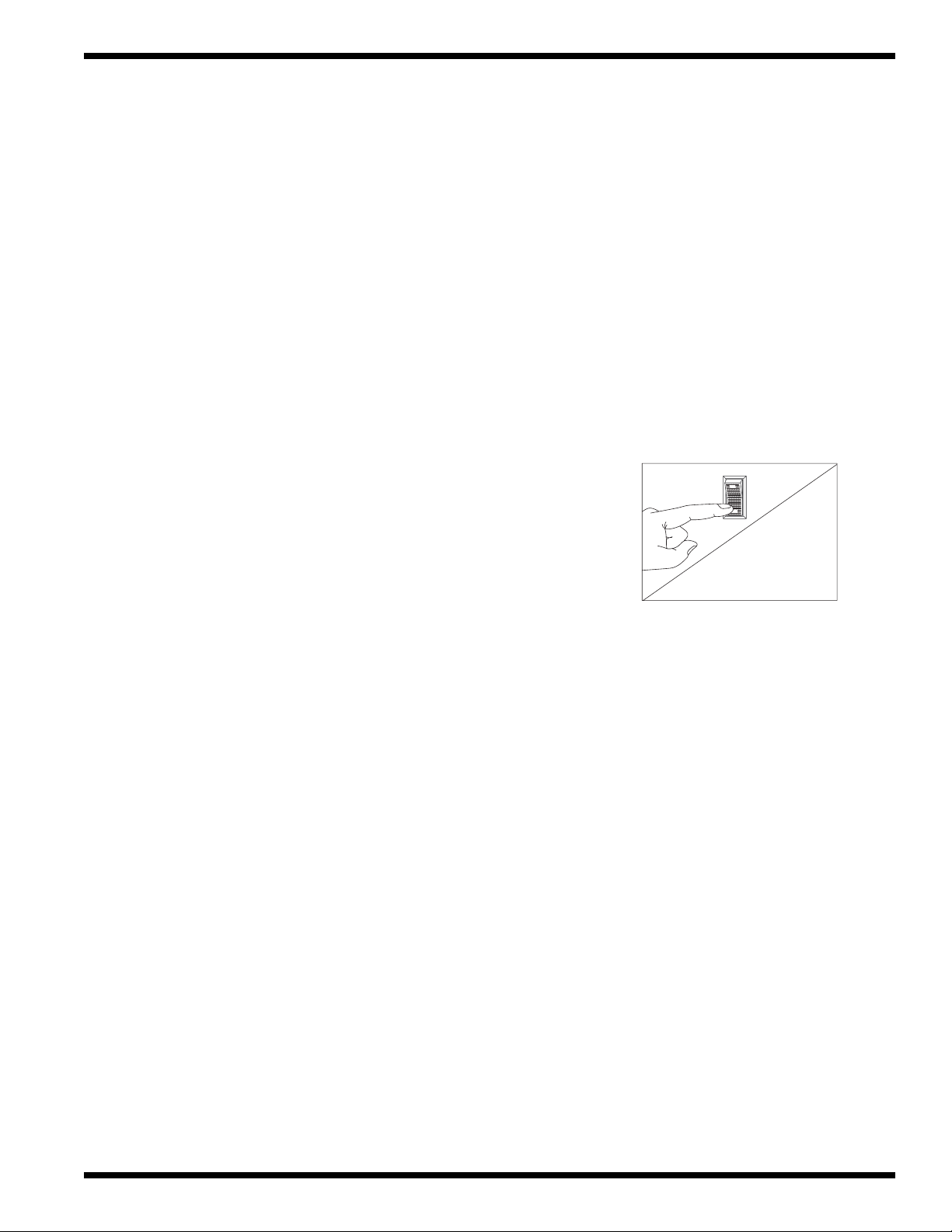
Motor Starter Overloads
Combination motor starters/Trip overloads are located to the left of the fuse blocks inside the
control cabinet. Each 3-phase motor has one Motor Starter overload to protect it from Line
Voltage electrical overloads. In addition, an auxiliary set of switch contacts is built into the
motor starter overload. The switch contacts disconnect 120VAC power to the Motor Contactor
Coils in the event of a overload condition. Refer to Fig. 10.
Note the Switch Lever on the Overload:
—If the switch lever is off with the “0” showing
then the overload has tripped on an overload.
To Reset the Motor Starter Overload:
—Flip the overload switch to the On position.
—Run the dishwasher and test the AMP
draw of the motor in question. If the motor
checks okay then there may be a wiring
problem or the overload may be defective.
24
To Replace a Motor Starter Overload:
—Disconnect the wires to the overload.
—Release the mounting catch on the front
side of the overload, push forward and lift out.
—Snap the new overload into place and reconnect
the wires.
To adjust the overload setting:
The screwdriver in Fig. 10 is positioned
to adjust the motor overload AMP setting.
—Read the FLA motor amps on the Motor Nameplate.
—Turn the setting to match the Nameplate.
Figure 10
Motor Starter Overload
Page 33

ELECTRICAL SERVICE
Pump Timer and Final Rinse Timer
Select Time Range
6 M
The timers have the following user-defined settings:
1. Adjustable time range
2. Timer knob setting
3. 50 Hz or 60 Hz setting
4. Indicator light (“ON” when timer is counting)
The Pump Timer is an OFF DELAY timer.
The Final Rinse Timer is an ON DELAY timer.
Each timer is clearly marked with a tag noting the
time set by the factory.
UP
Omron
H2C
2
1
0
Front View
60 S
3
4
5
6
50
60
Select to Match Incoming
4
3
2
1
Rear View
Power
5
6
7
8
Figure 11
Timers
To Replace a Timer:
—Disconnect power to the machine at the main service switch.
—Remove the defective timer and install the replacement.
—Adjust the new timer setting to match the setting of the original timer.
To Check the Pump Timer Setting: To Check the Final Rinse Timer Setting:
—Turn the power on. — Turn the power on.
— Place an object on the conveyor. — Place on object on the conveyor.
—Press the Green start button. The — Press the Green start button. The
conveyor will start. conveyor will start.
—When the object enters the load end — When the object enters the tunnel the
tunnel the pumps will start. pumps will start.
—Wait for the object to exit the tunnel at — Wait for the final rinse to begin.
the unload end. — Press the Red stop button the instant
—When the pumps stop, push the the final rinse begins.
conveyor shut-off shelf to stop — Open the power rinse tank door and
the conveyor. measure the distance between the
— Measure the distance between the exit object and the final rinse pipes.
end of the tunnel and the object. — The object should be 2 feet from
—The object should be about 1 foot past entering the final rinse area.
the end of the tunnel. — If the distance is less than 2 feet
— If the distance is less than 1 foot, between the object and the final rinse
increase the pump timer setting 10 pipes then, decrease the final rinse
seconds. Continue to increase the timer timer setting 10 seconds. Continue this
setting in 10 second increments until process until the proper distance
the proper distance is reached. is reached.
— If the measured distance is greater than — If the measured distance is greater
1 foot, decrease the pump timer setting than 2 feet then, increase the final
10 seconds. Continue to decrease the rinse timer setting 10 seconds.
timer setting in 10 second increments Continue this process until the proper
until the proper distance is reached. distance is reached.
— Run a final test to check both timer
settings.
25
Page 34

ELECTRICAL SERVICE
ELECTRICAL SERVICE (Continued)
Electric Eye Energy Sentinel System (Idle Pump Shut-off/Rinse Saver)
Circuit Explanation—
The electric eyes are infrared sensors and are located on the load end of the machine. The
sensors consist of an emitter and a receiver. These components switch the 120VAC control
voltage supplied to the pump timer.
When an object moving on the conveyor breaks the infrared beam between the eyes, contacts
(EER) close and complete the 120VAC circuit (Wires #7 and #27 in the control cabinet).
• The pump timer resets and the pump motors start.
• The pump timer and the final rinse timer begin to time down.
• The pump timer resets each time the beam is broken.
Component Location—
Refer to Fig.12:
The Emitter is mounted on the back of the load section.
The Receiver is mounted on the front of the load section.
Cleaning—
Be sure the emitter and receiver lenses are clean.
Wipe the lenses clean with a soft cloth and
common rubbing alcohol.
Alignment—
Electric eyes do not normally require aligning
except when replacing a defective unit.
The eyes are aligned visually. Make
sure they oppose one another across the
conveyor belt.
Replacement—
Receiver Emitter
Figure 12
Electric Eye Location
1/16"
26
1. The Emitter is coded T183E
2. The Receiver is coded T18RW3R.
Figure 13
Electric Eye Mounting
3. Remove the electric eye from the stainless steel cover.
Disconnect the cable.
4. Refer to Fig.13 and mount the new eye in its cover using the nut provided.
Recess the sensor 1/16" in the cover to protect the lens.
Page 35

ELECTRICAL SERVICE
Receiver
Emitter
Green LED
Power ON
indicator
Green LED
Power ON
indicator
Only
Yellow LED
Output indicator
Electric Eye Energy Sentinel System (Cont.d)
Electric Eye Bypass Switch—
NOTE:
All Upright Conveyor models have a switch located in the center of
the main control cabinet for bypassing the Electric Eye Energy
Sentinel System (See Fig.14).
Place the switch in the Automatic position to activate the Electric Eye
system.
—Pumps run when an object enters the load end tunnel.
—Timers control the pump run time and the final rinse.
(Refer to the Pump Timer and Final Rinse Timer service section for instructions on timer settings)
Place the switch in the Manual position to disconnect the Electric Eye System.
—Pumps and final rinse run continuously when the Green start button is pressed.
—Pumps and final rinse shut down when the Red stop button is pressed.
Troubleshooting—
Figure 14
Bypass Switch
• A failure in the electric eye system most often results in the following conditions:
1. Pumps run constantly.
2. Pumps will not run at all.
• Inspect the components to isolate the defective component:
1. Make sure that the bypass switch is in the automatic position.
2. Inspect and clean the lenses of the receiver and the emitter.
3. Check that electric eyes are aligned.
• Check the indicator lights on the back of the electric eyes: (See Figure 15.)
1. Remove two screws holding electric eye covers. Rotate covers away from tunnel
end so you can see indicator lights inside the covers. Do not remove eyes from covers.
2. Make sure that the electric eyes are aligned opposite of each other across the belt.
3. Make sure that both Green LED’s are ON.
4. Block the beam completely. The Receiver Yellow LED should be OFF.
5. Unblock the beam completely. The Yellow LED should be ON.
6. If all LED’s check OK, but the system fails to operate, try replacing the receiver first,
and then the emitter.
Figure 15-
Electric Eye
Indicator Lights
27
Page 36

ELECTRICAL SERVICE
ELECTRICAL SERVICE (Continued)
Automatic Fill/Low Water Heat Protection
Dual Float Switches—
Refer to Fig. 16
Each tank contains a dual float. The device consists of an
angled stem containing two reed switches. Two stainless steel
ball floats slide over the stem and are free to move up and
down. The floats contain magnets. When the float moves on
the stem, it opens and closes its associated reed switch inside
the stem. The reed switches control relays. The relays control
the automatic fill and heat for different parts of the machine.
Float switches and their relays operate on 24VAC.
Circuit Explanation—
The following is a general explanation of the float switch
circuit. Refer to the electrical schematic on your machine for a
detailed description of the individual floats, relays, and wiring.
Bottom Float and Reed Switch:
-The bottom float controls the heat.
-When the bottom float is down, the bottom reed switch is Normally Open (NO).
-When the bottom float is up, the bottom reed switch is Normally Closed (NC).
Top Float and Reed Switch:
-The top float controls a fill valve.
-When the top float is down, the top reed switch is Normally Open (NO).
-When the top float is up, the top reed switch is Normally Closed (NC).
The Top and Bottom Floats work together:
Initial Fill—
-When the tank is completely empty, the top float is down and its reed switch is NO.
-The control relay for the float switch is de-energized.
-The fill valve for the tank is energized and the tank begins to fill with water.
- As the water level in the tank rises, the bottom float begins to move up.
-When the bottom float is completely up, its NO reed switch contacts close.
-This prepares the heat circuit, but the heat Does Not energize at this time.
-The tank continues to fill until the top float is completely up.
-The top float’s NO reed switch contacts close. Its control relay energizes.
-The fill valve de-energizes.
-The heat circuit energizes through the NC contacts of the bottom float and
the contacts of the control relay.
Dual Float Switch Assembly
Figure 16
28
During Normal Operation—
- If the water level in a tank falls below the level of the top float, the top float moves
down and its reed switch contacts open.
-When the water level falls below the level of the bottom float, the bottom float moves
down and its reed switch opens.
-The control relay de-energizes. The fill valve energizes and refills the tank.
-The heat circuit will de-energize until the water level in the tank raises the top float again.
-The bottom float keeps the heat circuit ready as long as the water level is above the
level of the bottom float.
Page 37

ELECTRICAL SERVICE
Automatic Fill/Low Water Heat Protection (Continued)
Troubleshooting:
Each dual float controls the fill and heat circuit for a particular part of the machine.
Refer to the chart below:
DUAL FLOAT POWER RINSE TANK WASH TANK PREWASH TANK
LOCATION ➠
DUAL FLOAT • 2CR control relay • 3CR control relay • 4CR control relay
CONTROLS ➠ • Water level in rinse tank • Water level in wash tank • Water level in prewash tank
• Rinse tank heat • Wash tank heat • NOTE: Prewash tank does not
have tank heat
• Booster tank heat —
(Champion Built-in Only)
• Fill through final rinse valve • Fill through wash tank • Fill through prewash tank
final rinse piping and fill solenoid valve fill solenoid valve
nozzles
• Water enters machine at • Water enters the machine
top of hood at top of hood
NOTE:
The Power Rinse Tank dual float controls the heat circuit of the OPTIONAL Champion
built-in booster (Steam or Electric). 120VAC Booster Control Voltage is supplied from the
rinse tank heat control thermostat to the booster heat control thermostat.
Identifying a Dual Float Problem:
The most common trouble conditions associated with a dual float failure are:
Wash / Prewash Tank Power Rinse Tank
1. The tank fills constantly. 1. The final rinse runs constantly/No rinse tank heat.
2. The tank heat will not come on. 2. The booster heat will not come on.
Inspect the Dual Float:
1. Be sure that the dual float assembly is clean and free of scale build-up.
2. Be sure that the stainless steel balls on the float assembly move up and down freely.
In addition to checking the float operation, perform the following—
System Checks:
1. All drain valves are fully closed.
2. Incoming water supply Flow Pressure is 20-22 PSI.
3. Fuses in control cabinet are good (Electric Heat Only).
4. Steam supply and steam traps operate correctly.
5. Tank Heat thermostats and/or High limit thermostats operate correctly.
6. Booster Heat thermostats and/or High limit thermostats operate correctly.
7. Electric Eye Bypass switch is in the Automatic position.
Refer to the Troubleshooting Diagrams on the next page.
29
Page 38

ELECTRICAL SERVICE
DUAL FLOAT TROUBLESHOOTING DIAGRAMS
Wash or Prewash
Tank Fills Constantly
Is Tank Full
of Water?
YES
Are the Float
Balls Up?
YES
Is Heat ON
when called
for?
YES
NO
NO
NO
Close
Drain
Valve
Clean
Float
Assy.
Replace
Dual
Float
Water Runs Constantly
Through Final Rinse Piping
To Fill Rinse Tank
Push
Conveyor
Shut-off Shelf
to
Stop Conveyor
Water Shuts OFF
NO
Is Tank Full
of Water?
YES
NO
YES
Machine is in
Final Rinse Mode
Not a
Dual Float
Problem
Close
Drain
Valve
Check
Solenoid
Valve
Figure 17
Dual Float
Troubleshooting
System
Checks
Are the Float
Balls Up?
YES
Is Heat ON
when called
for?
YES
Check
Solenoid
Valve
NO
NO
Clean
Float
Assy.
Replace
Dual
Float
System
Checks
30
Page 39

ELECTRICAL SERVICE (Continued)
ELECTRICAL SERVICE
Thermostat Locations and Adjustments
Refer to Fig. 18
Electric tank heat is controlled by two thermostats:
1. The Control Thermostat which regulates the temperature.
2. The High Limit Thermostat which protects from
overheating.
Location:
Tank with Refuse Bucket – Both thermostats located
on the side of the tank.
Tank without Refuse Bucket – Both thermostats located
Electric Tank Heat Thermostats
on the front of the tank.
Adjustment:
The Control Thermostat has an adjustment screw on one side.
— The thermostat is wired Normally Closed.
— Turn the adjustment screw clockwise to increase the temperature in the tank and
counterclockwise to decrease the temperature in the tank.
The High Limit Thermostat is not adjustable. It contains a red reset button in its center.
— The red button pops out if the temperature in the tank exceeds 210°F.
— Press the red button in to reset the high limit.
Determine the cause of the high temperature condition.
Refer to Fig. 19 and Fig. 20.
Electric Booster Heat is controlled by two thermostats:
1. The Control Thermostat which regulates
the temperature.
2. The High Limit Thermostat which
protects from overheating.
3. Each tank has a control and a
high limit thermostat.
Location:
The control thermostats are enclosed in black
boxes mounted in front of the booster tanks on the
base of the unload section of the machine. The high limit
thermostats are enclosed in boxes mounted on the top of each
booster tank.
Control
Adjustment:
The control thermostat has an adjustment screw on one side.
— The thermostat is wired Normally Closed.
— Turn the adjustment screw clockwise to increase the booster tank temperature
and counterclockwise to decrease the booster tank temperature.
The High Limit Thermostat is a bimetal snap design. It is not adjustable.
—A button with a red dot in the center pops out when the temperature exceeds 210°F.
— Press the red reset button in to reset the high limit. Determine the cause of the
high temperature condition.
Tank Heat and Booster Heat (Steam)
Control thermostats regulate the steam supplied for tank heat and steam booster. The
control thermostats are the same type as the electric heat. High limit thermostats are
not required. High temperature protection is supplied by a steam pressure relief valve.
Figure 18
High Limit
Control
High
Limit
Figure 19
Electric Booster
Thermostats
Figure 20
Booster High Limit
31
Page 40

ELECTRICAL SERVICE
ELECTRICAL SERVICE (Continued)
Motors
Motor Specifications: Wiring Connections
Voltage: Standard motors are multi-voltage
Low Voltage: 208-230V
High Voltage: 460V
Non-standard motors are single voltage
575V (Canada)
Phase: All motors are 3-phase.
Horsepower: Prewash Pump: 1, 2 or 3 HP
Wash Pump: 3 HP
Rinse Pump: 3 HP
EconoRinse Pump: 1/4 HP
Conveyor Drive: 1/2 HP
Blower dryer: 2 HP
Troubleshooting:
Motor will not run:
1. Check incoming 3-phase power to control cabinet.
2. Check for tripped motor starter overload in control cabinet.
(Refer to Motor Starter overload service section for the proper setting)
3. Check for 3-phase power at motor contactor.
Motor runs hot and trips motor starter overload:
1. Check for proper voltage between L1-L2, L2-L3, L1-L3.
2. Check FLA on motor leads L1, L2, L3 using amp tester.
(Motor full load amp (FLA) ratings are stamped on motor nameplate).
Refer to the diagrams below for
Low Voltage
208-230 V
Figure 21
Motor Wiring Connections
High Voltage
460 V
32
Motor Replacement:
1. Disconnect the power to the machine.
2. Disconnect the wires at the motor junction box.
3. Make note of the motor connections in order to phase the replacement correctly.
4. Install the new motor and check for proper rotation.
5. Proper shaft rotation is clockwise looking at the rear of the motor.
6. Replacement motors are available as complete assemblies.
7. Champion cannot provide replacement bearings, stators, or rotors
as individual motor repair parts.
8. When requesting a replacement motor, please have available:
—The machine model number.
—The machine serial number.
—The motor location, i.e. (prewash tank, conveyor drive, etc.)
and the machine voltage.
Page 41

MECHANICAL SERVICE
Pump Flange
Seal Assy.
Impeller
Gaskets
Volute
Plug
Bolt
(A)
Nut
Backing Plate
Mtg. Nut
Backing Plate
Washer
Bolt
(B)
Water
Slinger
!
MECHANICAL SERVICE
PUMP SEAL REPLACEMENT:
WARNING:
Disconnect all
power to the
machine at the
main power
source and
place a tag at
the disconnect
switch to show
that work is
being done on
the circuit.
1. Disconnect the power to the machine.
2. Drain the machine. Remove the plug from the lowest point on the pump volute and drain
the pump.
3. Remove the pump hoses.
4. Disconnect the wires to the motor at the motor junction box.
5. Unbolt the motor from the base of the machine and remove the motor and pump.
6. Remove all the bolts (A) on the volute and carefully remove the volute from
the pump flange.
7. Lock the motor shaft holding the square end of the rear shaft with a wrench or vise grips.
8. Remove the impeller retaining bolt (B). Remove the large retaining nut and washer.
9. Remove the impeller using a strap wrench. Turn it counterclockwise.
Do not strike the impeller with a hammer to loosen or remove it.
10. Remove the old seal and discard. Check the seal seat in the pump flange
and clean thoroughly.
11. Clean the seating surface on the motor shaft with #600 emory paper or crocus cloth.
12. Check the water slinger and replace if worn or missing. Remove the (4) backing plate mtg.
nuts to gain access to the slinger.
13. Press the rubber seal and ceramic into the pump flange. Use a water soluble lubricant.
Keep the ceramic clean.
14. Install the rotating part of the seal on the shaft with the graphite surface toward the
ceramic. Use a water soluble lubricant.
15. Reinstall the impeller, washer, lock-nut, and bolt. Install new flange gaskets.
Bolt the volute to the flange.
16. Reinstall the pump and motor assembly on the base of the machine and reconnect the
pump hoses.
17. Reconnect the power and fill the tank with water. Check for leaks.
18. Bump start the pump to check the motor for correct rotation.
19. Proper shaft rotation is clockwise looking at the rear of the motor.
Figure 22
Pump Seal Replacement
33
Page 42

MECHANICAL SERVICE
MECHANICAL SERVICE (Continued)
Cross Flow Elbows
Proper water levels are maintained in the
tanks through a system of pipes and elbow
fittings. This system is called a water cross
flow system. Water flows by gravity from
the final rinse end of the machine back
towards the prewash tank.
Cross flow elbows are placed in the tanks as
required to adjust the flow of water from one
tank into the other. The proper adjustment of
the elbows is important for the correct
operation of the machine.
— IMPORTANT NOTE —
Cross flow elbow adjustment procedures can
be found in Appendix C at the end of this
manual. Refer to those instructions before
changing the position of any cross flow elbow.
Solenoid Valve Repair:
Champion uses Asco and Parker solenoid valves. Repair kits
and replacement coils are available from Champion
Industries and Champion Parts Distributors.
Refer to Fig. 24 and Fig. 25
To Repair a solenoid Valve:
1. Turn off the water or steam supply.
2. Disconnect the power to the machine.
3. If repairing a Parker valve:
a. Remove the screw holding the coil.
b. Lift the coil off the bonnet.
c. Unscrew the top of the valve.
d. Inspect the valve body. If pitted or scored,
replace the entire valve.
e. Replace the parts contained in the repair kit.
Reassemble the valve.
4. If repairing an Asco valve:
a. Remove the cap holding the coil.
b. Remove the (4) bonnet bolts.
c. Inspect the valve body and replace if pitted.
d. Replace the parts in the kit. Reassemble the valve.
Cross-flow elbow
X
Tank bottom
Figure 23
Cross Flow Elbow
Figure 24 - Parker Valve
34
Figure 25
Asco Valve
Page 43

REPLACEMENT PARTS
REPLACEMENT PARTS
35
Page 44

REPLACEMENT PARTS
16
20
24
19
18 22
21
16
25
23
25
11
9
12
2
13
10
14
1
8
7
6
5
4
8
7
6
5
4
3
15
26
17
45
46
47
27
28
43
44
30
37
36
31
38
35
42
39
40
34
30
SHAFT
33
27
29
32
41
36
Figure 26 - Load Section
Page 45

REPLACEMENT PARTS
LOAD SECTION
Fig. 26 Part Part Description Qty
Item No. No.
1 112446 Curtain (32 x 19) Entrance......................................................... 1
2 108642 Rod, Curtain (5/16 x 33-5/8)...................................................... 1
3 320895 Door, Access (8 x 27-5/8).......................................................... 1
4 112057 Latch, Access Door (per Door).................................................. 2
5 320578 Hinge, Access Door (per Door) ................................................. 4
6 320579 Plate, Access Door Hinge .......................................................... 2
7 100750 Screw (6-32 x 3/8) Flat Head..................................................... 4
8 104971 Nut, Grip 6-32 ............................................................................ 4
9 320901 Bracket, Perimeter Panel............................................................ 4
10 112267 Fastener, J-Clip........................................................................... 4
11 100073 Screw (1/4-20 x 1/2) Truss Head............................................... 4
12 107967 Nut, Grip (1/4-20 w/Nylon Insert) ............................................. 4
13 106482 Washer, Lock (1/4 Split) ............................................................ 4
14 106026 Washer, Flat (1/4 x 5/8 x 1/16 SST) .......................................... 4
15 320893 Door, Access (8 x 14) ................................................................ 1
15 322008 Door, Access (8 x 16) ................................................................ 1
16 201589 Damper, Regulator Assembly .................................................... 1
17 401486 Stack, Vent (4 x 24).................................................................... 1
18 112242 Receiver, Electric Eye ................................................................ 1
19 107003 Load, Placard.............................................................................. 2
20 112245 Union, Bulkhead 3/8 Plastic ...................................................... 2
21 205907 Tubing ........................................................................................ 2
22 112241 Emitter, Electric Eye .................................................................. 1
23 323229 Electric Eye Weldment RH ........................................................ 1
24 323230 Electric Eye Weldment LH ........................................................ 1
25 108954 Nut Grip 6-32 w/nylon insert..................................................... 4
26 106153 Flushing Nozzle ......................................................................... 2
NS 106382 Screw 6-32 x 3/8 Truss Head..................................................... 2
NS 107033 Washer .208 x .437 x .047 ......................................................... 2
27 108417 Nut, Retaining ............................................................................ 2
28 309711 Tee & Elbow Weldment L-R...................................................... 1
28 323595 Tee & Elbow Weldment R-L...................................................... 1
29 309709 Elbow Weld, Flushing ................................................................ 1
30 105994 Clamp, Hose............................................................................... 2
31 107935 Tube (5/8 ID x 5/16 OD) ........................................................... A/R
32 309386 Track, Take-up Bearing Assembly............................................. 4
33 109959 Bearing, Idler Shaft .................................................................... 2
34 111082 Roll Pin....................................................................................... 2
35 309397 Screw, Adjusting ........................................................................ 2
36 107691 Nut, Jam ..................................................................................... 2
37 109029 Plug, Plastic................................................................................ 2
38 309385 Bracket, Take-up ........................................................................ 2
39 110085 Nut, Castle.................................................................................. 2
40 406225 Station, Start/Stop (Includes Items 40-47)................................. 1
41 107617 Nameplate, Stop ......................................................................... 1
42 107614 Nameplate, Start......................................................................... 1
43 111616 Contact Block, NC ..................................................................... 1
44 111617 Contact Block, NO..................................................................... 1
45 111615 Pushbutton, RED (Stop)............................................................. 1
46 111614 Pushbutton, GREEN (Start) ....................................................... 1
47 113140 Boot, Silicone, Pushbutton......................................................... 1
37
Page 46

REPLACEMENT PARTS
16
21
12
14
2
3
22
15
18
13
1
2
3
43
41
17
57
45
42
44
20
24
40
39
28
25
36
29
30
27
38
26
23
37
36
19
31
32
5
6
8
7
10
11
33
9
4
34
35
38
46
51
52
56
47
52
48
Figure 27 - Prewash Section
51
53
49
54
55
5050
31
Page 47

REPLACEMENT PARTS
PREWASH SECTION
Fig. 27 Part Part Description Qty
Item No. No.
1 308900 Door, (12" B2 Section Standard) ............................................... 1
1 307882 Door, (24" B4 Section Standard) ............................................... 1
1 308887 Door, (12" B2 Section Lift-Out) ................................................ 1
1 306953 Door, (24" B4 Section Lift-Out) ................................................ 1
2 108966 Handle, Door (per Door)............................................................ 1
3 100073 Screw (1/4-20 x 1/2) Truss Head............................................... 2
4 109072 Drain Valve................................................................................. 1
5 113622 Thermometer (4 ft.) Gas Filled (Replaces 108391)................... 1
6 320901 Bracket, Perimeter Panel............................................................ 4
7 112267 Fastener, J-Clip........................................................................... 4
8 100073 Screw (1/4-20 x 1/2) Truss Head............................................... 4
9 107967 Nut Grip ( 1/4-20 w/Nylon Insert)............................................. 4
10 106482 Washer, Lock (1/4 Split) ............................................................ 4
11 106026 Washer, Flat (1/5 x 5/8 x 1/16 SST) .......................................... 4
12 112445 Curtain, Short (32 x 14) ............................................................. 1
13 108642 Rod, Curtain (5/16 x 33-5/8)...................................................... 1
14 320922 Basket, Refuse (B2 Section) ...................................................... 1
14 321969 Basket, Refuse (B4 Section) ...................................................... 1
15 305706 Cover, Refuse (B2 Section)........................................................ 1
15 305720 Cover, Refuse (B4 Section)........................................................ 1
16 305705 Screen, Scrap (B2 Section) ........................................................ 1
16 320921 Screen, Scrap (B3 w/o Optional Refuse Bucket)....................... 1
16 321972 Screen, Scrap (B4 w/ Optional Refuse Bucket)......................... 1
16 321990 Screen, Scrap (B4 w/o Optional Refuse Bucket)....................... 1
17 308322 Overflow ( 7-3/4") Before S/N J1436........................................ 1
17 325838 Overflow ( 8-1/2") After S/N J1436 .......................................... 1
18 304816 Strainer (6" Diameter)................................................................ 1
19 100141 Nut Grip 1/4-20 SST.................................................................. 1
20 319742 Hood, Pump Suction .................................................................. 1
21 319743 Plate, Pump Suction ................................................................... 1
22 313300 Flange Weld Suction .................................................................. 1
23 104640 Gasket 4Sq x 1/8TK................................................................... 1
24 100740 Bolt 5/16-18 x 1 Hx head........................................................... 4
25 100154 Nut Plain 5/16-18 ....................................................................... 4
26 106013 Washer, Lock 5/16 Split............................................................. 4
27 102376 Washer, 5/16 x 3/4 x 1/16 .......................................................... 4
28 320779 Upper, Manifold B2 ................................................................... 1
28 317240 Upper, Manifold B3 ................................................................... 1
28 317237 Upper, Manifold B4 ................................................................... 1
29 320780 Lower, Manifold B2................................................................... 1
29 320283 Lower, Manifold B3................................................................... 1
29 317240 Lower, Manifold B4................................................................... 1
30 111456 Locking Plate (per Spraypipe) ................................................... 1
31 111478 Bolt 10-32 x 1/2 Hex Hd SST (per Locking Plate) ................... 1
32 111505 O-Ring, Spraypipe (per Spraypipe) ........................................... 1
33 321472 Spraypipe B2.............................................................................. 2
39
Page 48

REPLACEMENT PARTS
Fig. 27 Part Part Description Qty
Item No. No.
33 321472 Spraypipe B3.............................................................................. 7
33 321472 Spraypipe B4.............................................................................. 9
34 104414 O-Ring, Spraypipe End Plug (per Spraypipe) ........................... 1
35 112240 Plug, Spraypipe End (per Spraypipe) ........................................ 1
** 900777 Spraypipe Assembly (includes 33, 34, 35) ................................ A/R
36 111456 Manifold Gasket (per Manifold) ................................................ 1
37 321307 Slide, Adjustable Restrictor, Lower Manifold........................... 1
38 319195 Plate, Adjustable Restrictor, Lower Manifold ........................... 1
39 104682 Washer, 1/4 Split Lock (per Manifold)...................................... 4
40 100736 Bolt, 1/4-20 x 3/4 Hex Head (per Manifold) ............................. 4
41 327102 Hook, Door Stop/Catch Combo................................................. 1
42 325920 Bracket & Door Stop/Catch Combo .......................................... 1
43 100734 Screw (1/4-20 x 5/8 Hex Head) ................................................. 2
44 100141 Nut, Grip (1/4-20) ...................................................................... 2
45 109069 Thermostat (Optional) Cold Water ............................................ 1
46 111019 Dual Float Switch....................................................................... 1
47 100500 Breaker, Vacuum 1/2 (bronze) ................................................... 1
*48 108349 Repair Kit, 1/2" Vacuum Breaker (not shown)
*48 113221 Repair Kit, 1/2" Vacuum Breaker (not shown)
49 111090 Hamlin Reed Switch .................................................................. 1
50 108954 Nut, Grip (6-32 w/Nylon Insert) ................................................ 2
51 100007 Screw (10-32 x 3/8) Truss Head ................................................ 2
52 100194 Nut, Grip (10-32) ....................................................................... 2
53 111026 Magnet, Large SST .................................................................... 1
54 319991-1 Cover, Door Switch/Bracket ...................................................... 1
55 319993 Back Plate, Door Switch Cover ................................................. 1
56 106486 Washer Lock #10 Split............................................................... 2
57 325922 Stop, Door Catch/Stop Combo .................................................. 1
*— 900836 Kit*Repair, 1/4" & 1/2" Vacuum Breaker
PREWASH SECTION (CONT.)
(Prior to S/N J1533) (bronze) .................................................... 1
(After S/N J1534) (plastic)......................................................... 1
(Includes one each of 108349, 113219 and 113221)
40
* Kit was created to repair either style (plastic or bronze) vacuum breaker. Plastic style
is no longer available.
Page 49

REPLACEMENT PARTS
16
14
15
19
13
12
1
2
3
26
25
27
16
18
17
20
29
28
21
45
47
22
40
23
33
24
42
32
6
8
37
5
9
10
7
11
34
36
38
39
4
30
35
31
42
48
44
46
61
55
55
60
56
56
57
49
2
3
50
51
52
Figure 28 - Wash/Rinse Section
43
53
58
41
59
5454
20
Page 50

REPLACEMENT PARTS
WASH / RINSE SECTION
Fig. 28 Part Part Description Qty
Item No. No.
1 307882 Door, (24"-C3/C4 Section Standard) ......................................... 1
1 306953 Door, (24"-C3/C4 Section Lift-out)........................................... 1
2 108966 Handle, Door (per Door)............................................................ 1
3 100073 Screw (1/4-20 x 1/2) Truss Head............................................... 2
4 109072 Drain Valve................................................................................. 1
5 113622 Thermometer (4 ft.) Gas Filled (Replaces 108391)................... 1
6 320901 Bracket, Perimeter Panel............................................................ 2
7 112267 Fastener, J-Clip........................................................................... 2
8 100073 Screw (1/4-20 x 1/2) Truss Head............................................... 2
9 107967 Nut, Grip (1/4-20 w/Nylon Insert) ............................................. 2
10 106482 Washer, Lock (1/4 Split) ............................................................ 2
11 106026 Washer, Flat (1/4 x 5/8 x 1/16 SST) .......................................... 2
12 112445 Curtain, Short (32 x 14) ............................................................. 1
13 108642 Rod, Curtain (5/16 x 33 5/8)...................................................... 1
14 317240 Upper Manifold (C3/C4 Section)............................................... 1
15 320283 Lower Manifold (C3 Section) .................................................... 1
15 317237 Lower Manifold (C4 Section) .................................................... 1
16 111456 Manifold Gasket (per Manifold) ................................................ 1
16 111456 Manifold Gasket (per Manifold) ................................................ 1
17 321307 Slide, Adjustable Restrictor, Lower Manifold........................... 1
18 319195 Plate, Adjustable Restrictor, Lower Manifold ........................... 1
19 111454 Locking Plate, Manifold (per Spraypipe) .................................. 1
20 111478 Bolt 10-32 x 1/2 Hex Hd SST (per Locking Plate) ................... 4
21 111505 O-Ring, Wash Arm (per Spraypipe) .......................................... 1
22 321472 Spraypipe, C3............................................................................. 7
22 321472 Spraypipe, C4............................................................................. 9
23 104414 O-Ring, Sprayarm End Plug (per Spraypipe) ............................ 1
24 112240 Plug, Spraypipe End (per Spraypipe) ........................................ 1
** 900777 Spraypipe Assembly (Includes Items 22, 23, 24) ......................
25 104682 Washer, 1/4 Split Lock (per Manifold)...................................... 4
26 100736 Bolt, 1/4-20 x 3/4 Hex Head (per Manifold) ............................. 4
27 320921 Screen, Scrap (C3 Section w/o Optional Refuse Bucket) ......... 2
27 322098 Screen, Scrap (C3 Section w/ Optional Refuse Bucket) ........... 2
27 321990 Screen, Scrap (C4 Section w/o Optional Refuse Bucket) ......... 2
27 321969 Screen, Scrap (C4 Section w/ Optional Refuse Bucket) ........... 2
29 109683 Flange ......................................................................................... 1
28 112257 O-Ring........................................................................................ 1
30 304816 Strainer (6" Diameter)................................................................ 1
31 107967 Nut, Strainer Retaining .............................................................. 1
32 319742 Hood, Pump Suction .................................................................. 1
33 319743 Plate, Pump Suction ................................................................... 1
34 313300 Flange Weld Suction .................................................................. 1
35 104640 Gasket 4Sq x 1/8TK................................................................... 1
36 100154 Nut Plain 5/16-18 ....................................................................... 4
37 100740 Bolt 5/16-18 x 1 Hex Head ........................................................ 4
38 106013 Washer Lock 5/16 Split.............................................................. 4
39 102376 Washer 5/16 x 3/4 X 1/16 .......................................................... 4
40 308321 Overflow 9" (C3/C4 Wash Tank w/ Refuse Bucket) ................. 1
43
Page 51

REPLACEMENT PARTS
Fig. 28 Part Part Description Qty
Item No. No.
40 305840 Overflow 9-1/2" (C3/C4 Wash Tank w/o Refuse Bucket)......... 1
40 305839 Overflow 10" (C3/C4 Rinse Tank w/o Refuse Bucket)............. 1
40 305840 Overflow 9-1/2" (C3/C4 Rinse Tank w/Refuse Bucket)............ 1
41 110852 Elbow, Cross-flow 1 x 90° (Wash Tank only) ........................... 1
42 109069 Thermostat, Control (Steam or Electric).................................... 1
43 110561 Thermostat, High Limit (Electric Only) .................................... 1
44 327102 Hook, Door Stop/Catch Combo................................................. 1
45 325920 Bracket, Door Stop.Catch Combo.............................................. 1
46 100734 Screw, Door Handle (1/4-20 x 5/8 Hex Head)........................... 2
47 100141 Nut, Grip (1/4-20 SST) .............................................................. 1
48 110854 Float Switch, Dual (C3 Wash Tank) (Before S/N J1436).......... 1
48 111019 Float Switch, Dual (C3 Rinse Tank) (Before S/N J1436) ......... 1
48 110854 Float Switch, Dual (C4 Wash/Rinse/WS Tank)
48 113291 Float Switch, Dual (Wash/Rinse Tank) (After S/N J1436)........ 1
49 321595 Basket, Refuse (Optional on C3 Section) .................................. 1
49 321969 Basket, Refuse (Optional on C4 Section) .................................. 1
50 308237 Cover, Refuse Basket (Optional on C3 Section) ....................... 1
50 305720 Cover, Refuse Basket (Optional on C4 Section) ....................... 1
51 100500 Vacuum Breaker 1/2" (bronze)................................................... 1
*52 108349 Repair Kit, Vacuum Breaker 1/2" (Not Shown)
*52 113221 Repair Kit, Vacuum Breaker 1/2" (Not Shown)
53 111090 Hamlin Reed Switch .................................................................. 1
54 108954 Nut, Grip (6/32 w/Nylon Insert) ................................................ 2
55 100007 Screw (10-32 x 3/8) Truss Head ................................................ 2
56 100194 Nut, Grip (10-32) ....................................................................... 2
57 111026 Magnet, Large SST .................................................................... 1
58 319991-1 Cover, Door Switch/Bracket ...................................................... 1
59 319993 Back Plate, Door Switch Cover ................................................. 1
60 106486 Washer Lock #10 Split............................................................... 2
61 325922 Stop, Door Catch/Stop Combo................................................... 1
— 900836 Kit*Repair, 1/4" & 1/2" Vacuum Breaker
WASH / RINSE SECTION (CONT.)
(Before S/N J1436) .................................................................... 1
(Prior to S/N J1533) (bronze) .................................................... 1
(After S/N J1534) (plastic)......................................................... 1
(Includes one each of 108349, 113219 and 113221)
44
* Kit was created to repair either style (plastic or bronze) vacuum breaker. Plastic style
is no longer available.
Page 52

REPLACEMENT PARTS
13
12
1
2
3
15
14
27
31
33
19
20
16
6
8
24
7
23
26
10
11
5
9
4
21
17
22
25
18
46
34
32
35
30
44
36
Figure 29 - EconoRinse Section
37
40
29
43
40
41
42
28
38
Page 53

REPLACEMENT PARTS
ECONORINSE SECTION OPTION
Fig. 29 Part Part Description Qty
Item No. No.
1 308900 Door, (12" Standard)............................................................................ 1
1 308887 Door, (12" Lift-out).............................................................................. 1
2 108966 Handle, Door (per Door)...................................................................... 1
3 100073 Screw (1/4-20 x 1/2) Truss Head......................................................... 2
4 109072 Drain Valve .......................................................................................... 1
5 113622 Thermometer (4 Ft.) Gas Filled (Replaces 108391)............................ 1
— 112089 Overlay, Gauge (Econorinse)............................................................... 1
6 320901 Bracket, Perimeter Panel...................................................................... 4
7 112267 Fastener, J-Clip .................................................................................... 4
8 100073 Screw (1/4-20 x 1/2) Truss Head......................................................... 4
9 107967 Nut, Grip (1/4-20 w/ Nylon Insert)...................................................... 4
10 106482 Washer, Lock (1/4 Split)...................................................................... 4
11 106026 Washer, Flat (1/4 x 5/8 X 1/16 SST) ................................................... 4
12 204949 Curtain, Short (32 x 10) ....................................................................... 1
13 111695 Rod, Curtain (5/16 x 32-3/4)................................................................ 1
14 323441 Scrap, Screen (w/o Optional Refuse Bucket/Standard) ....................... 1
14 323547 Scrap, Screen (w/ Lift-out Doors)........................................................ 1
14 324522 Scrap, Screen Reinforced..................................................................... 1
15 109683 Flange ................................................................................................... 1
16 112257 O-Ring.................................................................................................. 1
17 304816 Strainer (6" Diameter).......................................................................... 1
18 107967 Nut, Strainer Retaining ........................................................................ 1
106026 Washer (1/4 x 5/8 x 1/16 SST) (Not shown) ....................................... 1
19 319743 Plate, Pump Suction ............................................................................. 1
20 322832 Hood, Pump Suction ............................................................................ 1
21 322818 Suction Weld Elbow E2....................................................................... 1
22 104640 Gasket, 4SQ x 1/8TK........................................................................... 1
23 100740 Bolt, 5/16-18 x 1 Hex Head................................................................. 4
24 100154 Nut, Plain 5/16-18 ................................................................................ 4
25 106013 Washer, Lock 5/16 Split ...................................................................... 4
26 102376 Washer, 5/16 x 3/4 x 1/16.................................................................... 4
27 322838 Overflow 11"........................................................................................ 1
28 109069 Thermostat, Control (Steam or Electric).............................................. 1
29 110561 Thermostat, High Limit (Electric Only) .............................................. 1
30 327102 Hook, Door Stop/Catch Combo........................................................... 1
31 325920 Bracket, Door Stop/Catch Combo ....................................................... 1
32 100734 Screw (1/4-20 x 5/8 Hex Head) ........................................................... 2
33 100141 Nut, Grip (1/4-20) ................................................................................ 1
34 111019 Float Switch, Dual................................................................................ 1
35 110852 Elbow, Cross-Flow (1 x 90') ................................................................ 1
36 100500 Breaker, Vacuum 1/2" (bronze) ........................................................... 1
*37 108349
*37 113221
38 111090 Switch, Reed ........................................................................................ 1
39 108954 Nut, Grip (6/32 w/ Nylon Insert) (Not Shown) ................................... 2
40 100007 Screw (10-32 x 3/8 Truss Head).......................................................... 2
41 100194 Nut, Grip (10-32) ................................................................................. 2
42 111026 Magnet, Large ...................................................................................... 1
43 106486 Washer, Lock #10 Split........................................................................ 2
44 325922 Stop, Door Catch/Stop Combo ............................................................ 1
* 900836 Kit*Repair, 1/4" & 1/2" Vacuum Breaker (Includes one each of 108349,
Repair Kit, 1/2" Vacuum Breaker (Not Shown) (Prior to S/N J1534)
Repair Kit, 1/2" Vacuum Breaker (Not Shown) (After S/N J1534)
113219 and 113221) Kit was created to repair either style (plastic or bronze)
vacuum breakers. Plastic style is no longer available.
(bronze) 1
(bronze) 1
47
Page 54

REPLACEMENT PARTS
28
28
Final Rinse
Piping Assy.
17
18
27
24
16
15
20
19
26
26
24
25
23
22
21
Stud
1
1
15
Econo-Rinse
Piping Assy.
5
6
7
3
2
2
5
67
9
4
Figure 30 - EconoRinse Piping/Final Rinse Piping
8
2
2
3
10
4
13 14
12
11
12
48
Page 55

REPLACEMENT PARTS
ECONORINSE PIPING ASSEMBLY
Fig. 30 Part Part Description Qty
Item No. No.
1 106734 Cap 1/2" Plastic.......................................................................... 2
2 180281 Nozzle, Pumped ......................................................................... 16
3 319583 Pipe, Spray E2 Pumped Rinse ................................................... 2
4 111505 O-Ring........................................................................................ 2
5 111478 Bolt 10-32 x 1/2" Hex Head ...................................................... 8
6 107033 Washer, Flat 10-32 ..................................................................... 8
7 111454 Plate, Locking ............................................................................ 2
8 320068 Manifold, E2 Rear...................................................................... 1
9 322399 Manifold, E2 Front..................................................................... 1
10 108345 Gasket, Manifold........................................................................ 1
11 100740 Bolt 5/16 x 1 Hex Head ............................................................. 4
12 102376 Washer, Flat 5/16........................................................................ 8
13 106013 Washer Lock 5/16 ...................................................................... 4
14 100154 Nut, Plain 5/16 ........................................................................... 4
15 319231 Bracket (1 Top) (1 Bottom)........................................................ 2
16 319271 Bracket (Top).............................................................................. 1
FINAL RINSE PIPING ASSEMBLY
Fig. 30 Part Part Description Qty
Item No. No.
17 201236 Locknut 3/4 NP .......................................................................... 1
18 108620 Gasket Rinse Pipe ...................................................................... 1
19 322921 Manifold, Weldment (L-R) ........................................................ 1
20 322833 Manifold, Weldment (R-L) ........................................................ 1
21 107033 Washer, Flat 10-32 ..................................................................... 1
22 106486 Washer, Lock #10....................................................................... 1
23 104985 Nut, Plain 10-32 ......................................................................... 1
24 313285 Spraypipe Final Rinse (C8)........................................................ 2
25 205128 Spraypipe Final Rinse Lower (C6) ............................................ 1
26 180282 Nozzle 1/8 Fresh Water Rinse (C8) ........................................... 12
— 180282 Nozzle 1/8 Fresh Water Rinse (C6) ........................................... 9
27 205127 Spraypipe Final Rinse Upper (C6)............................................. 1
28 106734 Cap 1/2 Plastic ........................................................................... 2
49
Page 56

REPLACEMENT PARTS
2
3
4
2
6
10
1
24
23
9
17
8
7
20 21
11
13
12
6
5
8
9
10
7
14
15
16
52
29
22
18
19
28 26
27
25
Figure 31 - Unload Section
Page 57

REPLACEMENT PARTS
UNLOAD SECTION
Fig. 31 Part Part Description Qty
Item No. No.
1 401486 Stack, Vent (4 x 24).................................................................... 1
2 201589 Damper, Regulator Assembly .................................................... 1
3 112445 Curtain, Long (32 x 19) ............................................................. 1
4 108642 Rod, Curtain (5/16 x 33-5/8)...................................................... 1
5 320894 Door, Access Side (7 x 7-1/2) ................................................... A/R
5 322008 Door, Access Side (8 x 16) ....................................................... A/R
6 112057 Latch, Access Door (per Door).................................................. 2
7 320578 Hinge, Access Door (per Door) ................................................. 4
8 320579 Plate, Access Door Hinge (per Door) ........................................ 2
9 100750 Screw (6-32 x 3/8 Flat Head) (per Door)................................... 4
10 104971 Nut, Grip 6-32 (per Door).......................................................... 4
11 320901 Bracket, Perimeter Panel............................................................ 4
12 112267 Fastener, J-Clip........................................................................... 4
13 100073 Screw (1/4-20 x 1/2) Truss Head............................................... 4
14 107967 Nut, Grip (1/4-20 w/ Nylon Insert)............................................ 4
15 106482 Washer, Lock (1/4 Split) ............................................................ 4
16 106026 Washer, Flat (1/4 x 5/8 x 1/16 SST) .......................................... 4
17 320895 Door, Access (8 x 27) ................................................................ 1
18 104682 Thermometer, Final Rinse.......................................................... 1
19 112090 Overlay, Final Rinse 180° - 195°............................................... 1
20 104429 Breaker, Vacuum (3/4") (bronze) ............................................... 1
21 108351 Repair Kit, Vacuum Breaker (3/4") (Not Shown)
(Prior to S/N J1533) (bronze) .................................................... 1
21 113223 Repair Kit, Vacuum Breaker (3/4") (Not Shown)
(After S/N J1534) (plastic)......................................................... 1
22 109812 Gauge, Pressure.......................................................................... 2
23 110244 Support, Pressure Gauge ............................................................ 1
24 107414 Tubing, Pressure Gauge (Not Shown) ....................................... 4
25 311403 Manifold, Final Rinse (Not Shown)........................................... 1
26 313825 Upper Pipe, Final Rinse ............................................................. 1
27 317343 Lower Pipe, Final Rinse............................................................. 1
28 104005 Nozzle, Upper Final Rinse Pipe (1/8" NPT-#8010)................... 6
28 104005 Nozzle, Lower Final Rinse Pipe (1/8" NPT-#8010) .................. 5
29 106734 Cap (1/2") ................................................................................... 2
* 900836 Kit*Repair, 3/4" Vacuum Breaker (Includes one each of item 21)
Kit was created to repair either style (plastic or bronze) vacuum breaker.
Plastic style no longer available.
53
Page 58

REPLACEMENT PARTS
2
4
3
1
3
4
2
5
8
10
10
8
9
7
9
54
9
3
4
2
5
Figure 32 - Drive Shaft Assembly
10
8
11
Page 59

REPLACEMENT PARTS
DRIVE SHAFT ASSEMBLY
Fig. 32 Part Part Description Qty.
Item No. No.
1 112244 Shaft, Idle ................................................................................... 1
2 108434 Sprocket, Conveyor Belt ............................................................ 3
3 107305 Key (1/4 x 1/4 x 1-1/2)............................................................... A/R
4 111480 Bolt, Sprocket Retaining (3/8-16 x 3/4)..................................... A/R
5 403980 Take-up Assembly...................................................................... 2
7 112243 Shaft, Drive ................................................................................ 1
8 108434 Sprocket, Conveyor Belt ............................................................ 3
9 107305 Key (1/4 x 1/4 x 1-1/2)............................................................... A/R
10 111480 Bolt, Sprocket Retaining (3/8-16 x 3/4)..................................... A/R
11 109958 Bearing, Drive ............................................................................ 2
12 109388 Shock Absorber (Located on drive shaft) (Not Shown) ............ 2
55
Page 60

REPLACEMENT PARTS
35
3
4
2
6
1
5
7
8
19 20 21 22 23
36
37
9
10
17
27
25
32
31
28
25
28
21
20
28
28
13
11
12
28
28
14
15
27
31
16
18
24
33
29
30
29
32
34
56
Figure 33 - Conveyor Drive and Shut-off Assembly
Page 61

REPLACEMENT PARTS
CONVEYOR DRIVE AND SHUT-OFF ASSEMBLY
Fig. 33 Part Part Description Qty.
Item No. No.
1 109958 Bearing, Drive ............................................................................ 2
2 106679 Key (1/4 x 1/4 x 2-1/2)............................................................... 1
3 100485 Clutch, Torque Limiter (Complete Assembly) .......................... 1
4 102315 Clutch Disc Assembly (Complete Set #350) ............................. 1
5 108013 Sprocket, Drive........................................................................... 1
6 104271 Bushing (.54" Long for Torque Limiter Clutch)........................ 2
7 101156 Chain (#50 5/8" Steel)................................................................ 5
8 101149 Link, Connecting........................................................................ 1
9 110076 Tensioner, Chain......................................................................... 1
10 106521 Sprocket, Idler ............................................................................ 1
11 110299 Gearbox, RH w/Bracket............................................................. 1
12 110300 Gearbox, LH w/Bracket ............................................................. 1
13 105285 Sprocket, Gearbox (11T)............................................................ 1
14 103174 Sheave, Gearbox (C6) ................................................................ 1
14 108088 Sheave, Gearbox (C8) ................................................................ 1
14 100451 Sheave, Gearbox (C8 w/Optional Water Saver) ........................ 1
14 100454 Sheave, Gearbox (C6 w/Optional Water Saver) ........................ 1
15 100794 V-Belt (C8, C8 w/Optional Water Saver) .................................. 1
15 100795 V-Belt (C6, C6 w/Optional Water Saver, C6 VSPD*)............... 1
15 100792 V-Belt (C6 VSPD*, C8 VSPD).................................................. 1
16 107615 Sheave, Motor (C6, C8) ............................................................. 1
16 100451 Sheave, Motor (C8 w/Optional Water Saver) ............................ 1
16 108212 Sheave, Motor (C6 w/Optional Water Saver) ............................ 1
17 107183 Motor, 1/2 HP (208-240/480V/60/3PH) .................................... 1
17 110207 Motor, 1/2 HP (208-240/480V/60/3PH) VSPD......................... 1
17 180230 Motor, 1/2 HP (575/60/3PH)...................................................... 1
17 180256 Motor, 1/2 HP (380V/50/3PH)................................................... 1
17 180038 Motor, 3/4 HP (208-240/480V/60/3PH) .................................... 1
18 309738 Cover, Conveyor Shut-off .......................................................... 1
19 309719 Finger, Short Conveyor Shut-off
(Standard Belt w/upper rod).......... 1
20 309718 Finger, Long Conveyor Shut-off (Standard Belt w/o upper rod) ....... 1
21 309555 Finger, Conveyor Shut-Off (Silverware Belt) (Not Shown) ...... 1
22 314956 Finger, Conveyor Shut-Off
(Combination long/short) (Not Shown) .... 1
23 315970 Finger, Conveyor Shut-Off (Insulated tray belt) (Not Shown) .. 1
24 316369 LH Assembly, Conveyor Shut-Off............................................. 1
25 316370 RH Assembly, Conveyor Shut-Off............................................. 1
26 316367 Top, Conveyor Shut-Off ............................................................. 1
27 202393 Flange Seal ................................................................................. 2
28 100007 Screw (10-32 x 3/8 Truss Head) ................................................ 6
29 106482 Washer Lock 1/4 Split................................................................ 8
30 100779 Screw (1/4-20 x 5/8 Truss Head)............................................... 4
31 104266 Bushing (3/8 x 3/4 x 3/8 Bronze) .............................................. 2
32 104586 Collar (3/8" SST) ....................................................................... 2
33 100735 Bolt (1/4-20 x 5/8 Hex Head) .................................................... 4
34 100141 Nut, Grip (1/4-20 SST) .............................................................. 4
35 100770 Lockwasher, Tab......................................................................... 1
36 111090 Hamlin Reed Switch .................................................................. 1
37 111026 Magnet SST................................................................................ 1
* Denotes Variable Speed Drive/Dc Drive Systems
57
Page 62

REPLACEMENT PARTS
12
DOOR
4
5
6
ECONO
RINSE
1/4
HP
24"
1
DOOR
2
4
C3
WASH
HP
24"
DOOR
2
4
C3
3
RINSE
HP
12"
1
DOOR
PRE
13
WASH
HP
B2/C6/E2 R-L
12
DOOR
5
6
ECONO
RINSE
1
3
1/4
HP
HP
24"
DOOR
C4
WASH
1
3
HP
24"
DOOR
C4
RINSE
12"
DOOR
1
PRE
1
WASH
HP
B2/C8/E2 R-L
Figure 34 - Baffles (R-L Direction Shown)
UC/CW BAFFLE SYSTEM
Fig. 34 Part Part Description Qty.
Item No. No.
1 322108 Baffle Development (Prewash, Wash, Rinse) ............................ A/R
2 324394 Baffle Development (C3, LH only)(See Note *)....................... A/R
3 111045 Elbow 1/2" x 45 PVC NPT (All Fill Sections).......................... A/R
4 306586-30 Lower Baffle (See Note Below**)............................................. A/R
5 322110 Baffle Weldment (RH Final Rinse)............................................ 1
6 322113 Baffle Weldment (LH Final Rinse) ............................................ 1
7 100007 Screw 10-32 x 3/8 Truss Head................................................... 2
8 107966 Nut, Grip 10-32 w/Nylon Insert................................................. 1
9 106482 Washer, Lock 1/4........................................................................ 2
10 100734 Bolt 1/4-20 x 1/2" Hex Head............................................. 2
Notes:
* Baffle used on the left hand side of the door on all C3 tanks Wash or Rinse Sections
**306586-30 is used on C3 and C6 sections at every break that joins a C3 Section
All B4 Sections should take a baffle on each end of the section.
58
Page 63

REPLACEMENT PARTS
2
1
UC-CW
3
6
4
8
5 6
Figure 35 - Peg Belt
11
2
7
1
UC-CW
10
60
3
7
4
5
6
Figure 36 - Peg Belt with Upper Rod
7
8
9
Page 64

REPLACEMENT PARTS
UC-CW PEG BELT
Note 1: Total number of Rod Sections required for belt replacement vary depending on Machine Length.
Note 2: Quantities listed below are per one (1) ROD SECTION.
Fig. 35 Part Part Description Qty.
Item No. No.
1 404104 Rod Section, Peg Belt, UC-CW................................................. A/R
2 110092 Link, Upright.............................................................................. 10
3 108378 Spacer (11/32 x 5/16)................................................................. 2
4 108438 Spacer (11/32 x 1-13/32) ........................................................... 8
5 108435 Link, Straight End, Stainless Steel ........................................... 4
6 108437 Roller, Plastic ............................................................................. 3
7 108875 Pin, Cotter .................................................................................. 2
8 108381 Rod, Drilled Stainless Steel (5/16 x 29-1/4).............................. 1
UC-CW PEG BELT with UPPER ROD
Note 1: Total number of Rod Sections required for belt replacement vary depending on Machine Length.
Note 2: Quantities listed below are per one (1) ROD SECTION.
Fig. 36 Part Part Description Qty.
Item No. No.
1 404106 Rod Section, Peg Belt w/ Upper Rod, UC-CW......................... A/R
2 110092 Link, Upright.............................................................................. 10
3 108378 Spacer (11/32 x 5/16)................................................................. 2
4 108438 Spacer (11/32 x 1-13/32) ........................................................... 8
5 100141 Nut, Grip (1/4-20 SST) .............................................................. 2
6 108435 Link, Straight End, Stainless Steel ........................................... 4
7 108437 Roller, Plastic ............................................................................. 3
8 108875 Pin, Cotter .................................................................................. 2
9 108381 Rod, Drilled Stainless Steel (5/16 x 29-1/4).............................. 1
10 202601 Rod, Threaded Stainless Steel (1/4 x 26)................................... 1
11 108439 Spacer (1/2 x 9/32 x 2-9/16) ...................................................... 9
61
Page 65

REPLACEMENT PARTS
2
1
UC-CW
3
2
6
4
Figure 37 - Flat Belt
14
7
12
6
1
UC-CW
11
5
13
8
10
62
16
3
15
4
5
6
Figure 38 - Insulated Tray Belt (Silverware Belt Optional)
7
9
8
Page 66

REPLACEMENT PARTS
UC-CW FLAT BELT
Note 1: Total number of Rod Sections required for belt replacement vary depending on Machine Length.
Note 2: Quantities listed below are per two (2) ROD SECTIONS.
Fig. 37 Part Part Description Qty.
Item No. No.
1 402237 TWO Rod Sections, Flat Belt, UC-CW..................................... A/R
2 110094 Link, Flat .................................................................................... 20
3 108378 Spacer (11/32 x 5/16)................................................................. 6
4 108438 Spacer (11/32 x 1-13/32) ........................................................... 16
5 108435 Link, Straight End, Stainless Steel ........................................... 8
6 108437 Roller, Plastic ............................................................................. 6
7 108875 Pin, Cotter .................................................................................. 4
8 108381 Rod, Drilled Stainless Steel (5/16 x 29-1/4).............................. 2
UC-CW INSULATED TRAY BELT
Note 1: Total number of Rod Sections required for belt replacement vary depending on Machine Length.
Note 2: Quantities listed below are per two (2) ROD SECTIONS.
Fig. 38 Part Part Description Qty.
Item No. No.
1 402238 TWO Rod Sections, Insulated Tray Belt, UC-CW.................... A/R
2 110094 Link, Flat .................................................................................... 16
3 109030 Link, Upright Poly ..................................................................... 8
4 204995 Link, Flat Modified .................................................................... 1
5 100141 Nut, Grip (1/4-20 SST) .............................................................. 2
6 108435 Link, Straight End, Stainless Steel ........................................... 8
7 108437 Roller, Plastic ............................................................................. 6
8 108875 Pin, Cotter .................................................................................. 4
9 108381 Rod, Drilled Stainless Steel (5/16 x 29-1/4).............................. 2
10 109282 Spacer (11/32 x 1-1/32) ............................................................. 4
11 109224 Rod, Threaded Stainless Steel (1/4 x 22-1/4) ............................ 1
12 102376 Washer (5/16 x 3/4 x 1/16) ........................................................ 2
13 108378 Spacer (11/32 x 5/16)................................................................. 2
14 109187 Spacer (9/32 x 1-13/32) ............................................................. 7
SILVERWARE BELT
15 109164 Link, Flat, Silverware Belt......................................................... 2
16 109163 Link, Side, Silverware Belt ........................................................ 4
63
Page 67

REPLACEMENT PARTS
2
5
3
8
4
UC-CW
6
7
64
Figure 39 - Stainless Steel Peg Belt
Page 68

REPLACEMENT PARTS
UC-CW STAINLESS STEEL PEG BELT
Note 1: Total number of Rod Sections required for belt replacement vary depending on Machine Length.
Note 2: Quantities listed below are per one (1) ROD SECTION.
Fig. 39 Part Part Description Qty.
Item No. No.
1 408013 Rod Section, Stainless Steel Peg Belt, UC-CW ........................ A/R
2 111421 Link, Stainless Steel Upright ..................................................... 10
3 109282 Spacer (11/32 x 1-1/32) ............................................................. 8
4 108378 Spacer (11/32 x 5/16)................................................................. 8
5 108435 Link, Straight End, Stainless Steel ........................................... 4
6 108375 Roller, Stainless Steel................................................................. 3
7 108381 Rod, Drilled Stainless Steel (5/16 x 29-1/4).............................. 1
8 108875 Pin, Cotter (Not Shown)............................................................. 2
UC-CW Stainless Steel Peg Belt with Upper Rod
(Items 2 thru 8 above and the Parts Listed Below)
— 100141 Nut, Grip (1/4-20 SST) (Not Shown) ........................................ 2
— 202601 Rod, Threaded (1/4 x 26) (Not Shown) ..................................... 1
65
Page 69

REPLACEMENT PARTS
4
5
4
5
3
1
2
6
9
10
7
8
14
11
2
12
13
15
16
2
1
2
25
34
36
35
32
33
17
18
31
37
30
Figure 40 - Pump Assembly
19
21
22
23
20
24
See bottom of Page 68 for
Optional EconoRinse Pump parts
27
28
26
22
22
23
29
66
Page 70

REPLACEMENT PARTS
PUMP ASSEMBLY
Fig. 40 Part Part Description Qty.
Item No. No.
1 110372 Hose, Pump Suction .................................................................. 1
2 104203 Clamp, Suction Hose.................................................................. 2
3 112409 Hose, Pump Discharge............................................................... 1
4 110858 Clamp, Discharge Hose (Standpipe side) .................................. 1
5 111964 Clamp, Discharge Hose.............................................................. 1
6 110420 Motor, 1 HP Prewash (208-240V/460V/60/3PH)...................... 1
6 180245 Motor, 1 HP Prewash (380V/50/3PH) ....................................... 1
6 180272 Motor, 1 HP Prewash (380V/60/3PH) ....................................... 1
6 180237 Motor, 1 HP Prewash (415/50/3PH) .......................................... 1
6 111739 Motor, 1 HP Prewash (575V/60/3PH) ....................................... 1
6 180210 Motor, 1 HP Prewash (600V/60/3PH) ....................................... 1
6 180212 Motor, 1 HP Prewash (220V/50/3PH) ....................................... 1
6 110422 Motor, 2 HP Prewash (208-240V/460V/60/3PH)...................... 1
6 180226 Motor, 2 HP Prewash (380V/50/3PH) ....................................... 1
6 180273 Motor, 2 HP Prewash (380V/60/3PH) ....................................... 1
6 180246 Motor, 2 HP Prewash (415V/50/3PH) ....................................... 1
6 111740 Motor, 2 HP Prewash (575V/60/3PH) ....................................... 1
6 110424 Motor, 3 HP Prewash, Wash/Rinse (208-240/460V/60/3PH).... 1
6 111741 Motor, 3 HP Prewash, Wash/Rinse (575V/60/3PH) .................. 1
6 180239 Motor, 3 HP Prewash, Wash/Rinse (415V/60/3PH) .................. 1
6 180257 Motor, 3 HP Prewash, Wash/Rinse (380V/50/3PH) .................. 1
7 110734 Stud, Motor ................................................................................ 1
8 109654 Slinger, Water ............................................................................. 1
9 100754 Screw, 10-32 x 1/2" Flat Head ................................................... 1
10 110270 Washer, Star Countersunk.......................................................... 1
11 204460 Plate, Backing ............................................................................ 1
12 106407 Washer, Lock.............................................................................. 1
13 107690 Nut, Jam 3/8-16.......................................................................... 1
14 111681 Flange, Pump.............................................................................. 1
15 111111 Seal, Shaft .................................................................................. 1
16 111941 Gasket (.0085") (1 Notch).......................................................... 1
17 111942 Gasket (.015") (2 Notches) ........................................................ 1
18 111943 Gasket (.032") (3 Notches) ........................................................ 2
19 113118 Impeller, SST (2.875") 1 HP...................................................... 1
19 113119 Impeller, SST (3.5") 2 HP.......................................................... 1
19 113120 Impeller, SST (4.0") 3 HP.......................................................... 1
20 102500 Plug, 1-1/4" NPT Brass.............................................................. 2
21 112380 Volute, Pump .............................................................................. 1
22 106482 Washer, Lock 1/4" Split ............................................................. 11
23 100736 Bolt, 1/4-20 x 3/4" Hex Head .................................................... 10
24 112338 O-Ring Gasket, Pump Suction Flange ....................................... 1
25 102504 Plug, 1/2" NPT Brass ................................................................. 1
26 112379 Flange, Suction........................................................................... 1
— 112338 Gasket-Pump, Suction................................................................ 1
67
Page 71

REPLACEMENT PARTS
Fig. 40 Part Part Description Qty.
Item No. No.
27 110248 Washer, Flat................................................................................ 1
28 110247 Nut, Hex Jam 7/16-20 ................................................................ 1
29 100734 Bolt, 1/4-20 x 1/2" Hex Head .................................................... 1
— 405919 Motor/Pump Assy. (Complete) 1 HP Prewash
— 405920 Motor/Pump Assy. (Complete) 2 HP Prewash
— 405921 Motor/Pump Assy. (Complete) 3 HP Prewash
— 405922 Motor/Pump Assy. (Complete) 3 HP C3 Section - Wash/Rinse
— 405923 Motor/Pump Assy. (Complete) 3 HP C4 Section - Wash/Rinse
PUMP ASSEMBLY (CONT.)
(208-240/480V/60/3PH)
(208-240/480V/60/3PH)
(208-240/480V/60/3PH)
(208-240/480V/60/3PH)
(208-240/480V/60/3PH)
ECONORINSE SECTION OPTION
Fig. 40 Part Part Description Qty.
Item No. No.
30 180280 Motor/Pump Assy. (Complete) 1/4 HP
(208-240/460V/60/3PH)..... 1
31 180327 Motor, 1/4 HP (208-240/460V/60/3PH) EconoRinse................ 1
32 900728 Pump Assembly (Less Motor) ................................................... 1
33 205202 Hose, Suction (1-5/8 I.D. x 4-3/4) ............................................. 1
34 107340 Clamp, Suction Hose.................................................................. 2
35 205201 Hose, Discharge (1-3/8 I.D. x 9-1/2) ......................................... 1
36 107340 Clamp, Discharge Hose.............................................................. 2
37 180326 Bolt (Pump to Motor)................................................................. 4
— 108598 Gasket, Pump (Not Shown) ....................................................... 1
— 180325 Seal, Shaft (Not Shown)............................................................. 1
— 112106 Impeller, 1/4 HP EconoRinse Pump (Not Shown) .................... 1
— 112107 Volute (Not Shown).................................................................... 1
— 900756 Kit*Volute, Impeller, Repair Kit (Not Shown)
— 900757 Repair Kit w/Seal, (Pump Gasket, Pump Shaft w/set screws,
Water Slinger, Shaft Seal)
68
Page 72

REPLACEMENT PARTS
10 KW Heater Elements
are longer than 5 KW
Heater Elements.
1
2
4
5
3
70
Figure 41 - Electric Tank Heat
Page 73

REPLACEMENT PARTS
ELECTRIC TANK HEAT
Fig. 41 Part Part Description Qty.
Item No. No.
1 107839 Element, Tank Heater (5KW, 208V/3PH).................................. A/R
1 107840 Element, Tank Heater (5KW, 240V/3PH).................................. A/R
1 107842 Element, Tank Heater (5KW, 480V/3PH).................................. A/R
1 111123 Element, Tank Heater (5KW, 575V/3PH).................................. A/R
2 109751 Element, Tank Heater (10KW, 208V/3PH)................................ A/R
2 107844 Element, Tank Heater (10KW, 240V/3PH)................................ A/R
2 107846 Element, Tank Heater (10KW, 480V/3PH)................................ A/R
2 111120 Element, Tank Heater (10KW, 575V/3PH)................................ A/R
3 108345 Gasket, Tank Heater (one per element)...................................... A/R
4 109069 Thermostat, Control (one per tank)............................................ 1
5 110561 Thermostat, High Limit (one per tank)...................................... 1
ECONORINSE SECTION (Optional)
Fig. 41 Part Part Description Qty.
Item No. No.
— 111258 Element, Tank Heater (15KW, 208V/3PH)................................ A/R
— 111259 Element, Tank Heater (15KW, 240V/3PH)................................ A/R
— 111260 Element, Tank Heater (15KW, 480V/3PH)................................ A/R
——Element, Tank Heater (15KW, 575V/3PH)................................ A/R
3 108345 Gasket, Tank Heater (one per element)...................................... A/R
4 109069 Thermostat, Control (one per tank)............................................ A/R
5 110561 Thermostat, High Limit (one per tank)...................................... A/R
71
Page 74

REPLACEMENT PARTS
10
2
5
Piping Steam Wash/Rinse w/Bucket Piping Steam E2
16
Piping Condensate E2
5
25
18
6
20
19
3
9
8
6
21
24
4
18
19
12
11
23
23
26
8 9 10
13
5
8
9
10
14
4
15
36
38
37
35
Figure 42 - Steam Tank Heat
39
27
1716
Piping Condensate Wash/Rinse
28
29
30
31
18
19
Piping Steam
Injector
Wash/Rinse
33
20
w/Bucket
3
3
3
21
23
18
22
10
9
2
5
12
32
8
9
10
4
8
2
32
13
4
12 13
34
Piping Steam Injector E2 (R-L)
12
19
24
3
2
5
74
Page 75

REPLACEMENT PARTS
STEAM TANK HEAT
Fig. 42 Part Part Description Qty.
Item No. No.
1 323828 Flange Weldment (C3 Section) .................................................. 1
1 323007 Flange Weldment (C4 Section) .................................................. 1
2 105739 Elbow, Red. 1" NPT x 3/4" NPT BI .......................................... 1
3 105847 Nipple Close 1" NPT BI ............................................................ 1
4 107211 Union Elbow, 1" NPT x 90° Female BI..................................... 1
5 105780 Union 1" NPT BI ....................................................................... 1
6 109969 Nipple, 1" NPT x 3 3/4" LG BI ................................................. 2
7 105864 Nipple, 1" NPT x 7" LG BI ....................................................... 1
8 110005 Valve Steam Solenoid (1" Asco)................................................ 1
9 110007 Repair Kit (1" Asco) .................................................................. 1
10 110120 Coil, Solenoid (1" Asco)............................................................ 1
11 323007 Flange Weldment (E2 Section) .................................................. 1
12 105850 Nipple, 1" NPT x 2" LG BI ....................................................... 1
13 105733 Elbow, 1" NPT x 90° BI ............................................................ 1
14 105867 Nipple, 1" NPT x 8 1/2" LB BI ................................................. 1
15 106840 Nipple, 1" NPT x 9" LG BI ....................................................... 1
16 323829 Flange Weldment (C3 Section) .................................................. 1
16 323007 Flange Weldment (C4 Section) (E2 Section)............................. 1
17 105738 Elbow, Red. 3/4" NPT x 1/2" NPT BI ....................................... 1
18 105782 Nipple, Close 1/2" NPT BI ........................................................ 2
19 105778 Union 1/2" NPT BI .................................................................... 1
20 105783 Nipple, 1/2" NPT x 2" LG BI .................................................... 1
21 111380 Steam Trap 1/2".......................................................................... 1
22 109580 Nipple, 1/2" NPT x 11" LG BI .................................................. 1
23 102288 Elbow 1/2" NPT x 90° BI .......................................................... 1
24 107488 Nipple, 1/2" NPT x 3 1/2" LG BI.............................................. 1
25 105723 Coupling, Red 3/4" NPT x 1/2" NPT BI ................................... 1
26 105785 Nipple, 1/2" NPT x 2 1/2" LG BI.............................................. 1
27 109069 Thermostat, Control ................................................................... 1
28 321000 Cover, Heater Box (C3 Section w/o Refuse Bucket)................. 1
28 322626 Cover, Heater Box (C4 Section w/o Refuse Bucket)................. 1
28 322812 Cover, Heater Box (E2 Section w/o Refuse Bucket) ................. 1
29 322625 Heater Box Weld (C4 Section w/o Refuse Bucket)................... 1
29 320998 Heater Box Weld (C3 Section w/o Refuse Bucket)................... 1
29 311811 Heater Box Weld (E2 Section w/o Refuse Bucket) ................... 1
30 314102 Dual Thermostat Box ................................................................. 1
31 109682 Cover (Box)................................................................................ 1
32 100854 Valve, Check 1" NPT ................................................................. 1
33 105856 Nipple, 1" NPT x 4" LG BI ....................................................... 1
34 106606 Nipple, 1" NPT x 6" LG BI ....................................................... 1
35 324447 Manifold, Weld Steam Injector (C3 Section) ............................ 1
35 309440 Manifold, Weld Steam Injector (C4 Section) ............................ 1
35 324448 Manifold, Weld Steam Injector (E2 Section)............................. 1
36 108345 Gasket, 3 x 3 x 1/8".................................................................... A/R
37 201110 Injector, Steam ........................................................................... 1
38 111371 Nipple, Toe 1" x 7" SST ............................................................ 1
39 109683 Flange ......................................................................................... A/R
75
Page 76

REPLACEMENT PARTS
2
5
1
11
4
1
4
12
13
3
1
14
15
14
10
16
8
14
9
7
6
19
18
17
76
26
23
24
25
22
20
23
21
Figure 43
Steam Coils (Low Pressure, Standard/High Pressure, EconoRinse)
22
21
20
Page 77

REPLACEMENT PARTS
LOW PRESSURE STEAM COILS
Fig. 43 Part
Item No. No. Part Description Qty.
1 100023 Street Elbow 3/4" NPTSST ....................................................... 3
2 101090 Nipple 3/4" NPT x 3" LG SST ................................................. 1
3 101589 Nipple 3/4" NPT x 19-3/4" LG SST.......................................... 1
4 102554 Union 4/4" NPT SST ................................................................. 2
5 323830 Coil Weldment Steam C3 (Low Pressure)................................. 1
6 102554 Union 3/4" NPT SST ................................................................. 2
7 100051 Nipple 3/4" NPT x Close SST ................................................... 2
8 102443 Elbow 3/4" NPT x 90º SST........................................................ 1
9 112890 Nipple 3/4" NPT x 18-3/4" LG SST.......................................... 1
10 323809 Coil Weldment Steam C4 (Low Pressure)................................. 1
STANDARD AND HIGH PRESSURE STEAM COILS
Fig. 43 Part
Item No. No. Part Description Qty.
11 100023 Street Elbow 3/4" NPT SST....................................................... 3
12 102554 Union 3/4" NPT SST ................................................................. 2
13 323862 Coil Weldment Steam (C3 Section, Wash/Rinse) ...................... 1
14 102443 Elbow 3/4" x 90º SST ................................................................ 3
15 100959 Nipple 3/4" x 1-3/4" SST........................................................... 1
16 101558 Nipple 3/4" x 13-3/4" SST......................................................... 1
17 100051 Nipple Close 3/4" SST ............................................................... 1
18 102554 Union 3/4" NPT SST ................................................................. 2
19 307384 Coil Weldment Steam (C4 Section, Wash/Rinse) ...................... 1
ECONORINSE STEAM COILS
Fig. 43 Part
Item No. No. Part Description Qty.
20 326855 Bracket, Steam Coil Weldment .................................................. 2
21 325629 Cap, Steam Coil Bracket............................................................ 2
22 107999 Cap, Screw 1/4-20 x 1-3/4 Hex Head SST................................ 4
23 102506 Plug 3/4" NPT SST .................................................................... 2
24 100051 Nipple Close 3/4" NPT SST ...................................................... 2
25 102554 Union 3/4" NPT SST ................................................................. 2
26 325545 Coil Weldment Steam (E2 Section, EconoRinse)...................... 1
77
Page 78

REPLACEMENT PARTS
1
2 3
15
4
22
20
21
19
10
25
26
13 14
11
24
24
25
16
12
18
23
22
21
25
24
8
7
5
20
19
24
25
4
4
17
5
12
4
8
7
11
18
10
6
5
78
Figure 44 - Electric Booster
Page 79

REPLACEMENT PARTS
ELECTRIC BOOSTER
Fig. 44 Part Part Description Qty.
Item No. No.
1 109887 Valve, Solenoid (3/4") ................................................................ 1
— 109903 Repair Kit, Solenoid Valve (3/4") .............................................. 1
— 108516 Coil, Solenoid Valve (3/4") ........................................................ 1
2 109886 Valve, Solenoid (1/2") (Prior to S/N J1533) .............................. A/R
— 109902 Repair Kit, Solenoid Valve (1/2") (Prior to S/N J1533) ............ 1
— 108516 Coil, Solenoid Valve (1/2") (Prior to S/N J1533) ...................... 1
2113352 Valve, Solenoid (1/2") (After S/N J1534).................................. A/R
—113392 Repair Kit, Solenoid Valve (1/2") (After S/N J1534)................ 1
—113357 Coil, Solenoid Valve (1/2") (After S/N J1534).......................... 1
3 107550 Valve, Pressure Reducing (3/4") ................................................ 1
4 109069 Thermostat, Control (one per tank)............................................ A/R
5110562 Thermostat, High Limit (one per tank)...................................... A/R
6110929 Box, High Limit Thermostat (one per tank) .............................. A/R
7 107033 Washer, Flat #10......................................................................... 2
8 107966 Nut, Grip (10-32 w/ Nylon Insert) ............................................. 2
9110930 Cover, Box, High Limit Thermostat (one per tank) .................. A/R
10 103217 Connector, Sealtite Elbow (1/2 x 90°)....................................... 1
11 102505 Plug, Brass (3/4 NPT) ................................................................ 1
*12 305407 Tank, Booster (Specify Model Number of Machine)................ A/R
13 111319 Screw (6-32 x 1/2 Truss Head) (two per box)........................... A/R
14 107966 Nut, Grip (10-32 w/ Nylon Insert) (two per high limit thermostat). A/R
15 100100 Screw (8-32 x 1/4 Rhd Head) (two per box) ............................. A/R
16 107922 Box and Cover Assembly, Thermostat (one per tank)............... A/R
17 104682 Thermometer (2" Stem) ............................................................. A/R
18 102505 Plug, Brass (3/4" NPT) (one per tank)....................................... A/R
19 106482 Washer, Split (1/4") (three per element) .................................... A/R
20 100003 Nut, Plain (1/4") (three per element) ......................................... A/R
21 108576 Cover, Booster (one per tank).................................................... A/R
22 107967 Nut, Grip (1/4-20 w/Nylon Insert) (three per booster cover) .... A/R
23 106026 Washer, Flat (1/4") (three per booster cover) ............................ A/R
24 111235 Element, Booster (5KW, 208V/3PH)......................................... A/R
24 111236 Element, Booster (5KW, 240V/3PH)......................................... A/R
24 111235 Element, Booster (5KW, 380V/3PH) (Connected WYE).......... A/R
24 111236 Element, Booster (5KW, 415V/3PH) (Connected WYE).......... A/R
24 111237 Element, Booster (5KW, 480V/3PH)......................................... A/R
24 111384 Element, Booster (5KW, 575V/3PH)......................................... A/R
25 111308 Element, Booster (9KW, 208V/3PH)......................................... A/R
25 111305 Element, Booster (9KW, 240V/3PH)......................................... A/R
25 111308 Element, Booster (9KW, 380V/3PH) (Connected WYE).......... A/R
25 111305 Element, Booster (9KW, 415V/3PH) (Connected WYE).......... A/R
25 108579 Element, Booster (9KW, 480V/3PH)......................................... A/R
25 111122 Element, Booster (9KW, 575V/3PH)......................................... A/R
26 109985 O-Ring, Booster Element (one per element) ............................. A/R
79
Page 80

REPLACEMENT PARTS
34
35
25
36
38
39
40
19
37
21
19
46
45
22
37
41
32
33
31
8
30
19
29
19
23
21
19
23
24
19
19
9
7
8
10
4
11
12
16
4
17
5
15
14
13
6
4
10
4
5
4
1
3
2
43
18
42
44
22
26
27
28
20
22
19
80
Figure 45 - Steam Booster 70° Rise Standard & Low Pressure
(R-L Direction and Standard Pressure Shown)
Page 81

REPLACEMENT PARTS
STEAM BOOSTER 70° RISE
Fig. 45 Part Part Description Qty.
Item No. No.
1112310 Amtrol Steam Booster #320....................................................... 1
2112355 Plug 2" NPT BI .......................................................................... 1
3 100981 Bushing Reducing 2" x 1" BI (Standard Pressure).................... 1
3 100983 Bushing Reducing 2" x 1-1/2" BI (Low Pressure) .................... 1
4 105847 Nipple, Close 1" NPT BI (Standard Pressure)........................... 2
4 105881 Nipple, Close 1-1/2" NPT BI (Low Pressure) ........................... 5
5 105780 Union 1" NPT BI (Standard Pressure)....................................... 1
5 103586 Union 1-1/2" NPTBI (Low Pressure) ........................................ 2
6110005 Valve Steam Solenoid 1" (Standard Pressure) ........................... 1
6112344 Valve Steam Solenoid 1-1/2" (Low Pressure) ........................... 1
—110007 Repair Kit 1" .............................................................................. 1
—110120 Coil, Solenoid 1"........................................................................ 1
7 102402 Bushing Red 1/2" x 1/2" NPT BI .............................................. 1
8 100123 Cock Gauge 1/4" ........................................................................ 2
9 105764 Tee Red 1" x 1/2" NPT BI (Standard Pressure)......................... 1
9 107004 Tee Red 1-1/2" x 1/2" x 1-1/2" NPT BI (Low Pressure)........... 1
10 106789 Nipple 1" x 2-1/2" NPT BI (Standard Pressure)........................ 2
11 100979 Bushing Red 1-1/2" x 1" NPT BI (Standard Pressure).............. 1
12 107657 Tee Red 2" x 1-1/2" NPT BI...................................................... 1
13 106607 Nipple Close 2" NPT BI ............................................................ 1
14 106051 Strainer Line 2" NPT BI ............................................................ 1
15 112353 Plug 1" NPT BI .......................................................................... 1
16 105881 Nipple Close 1-1/2" NPT BI (Standard Pressure) ..................... 1
17 103586 Union 1-1/2" NPT BI (Standard Pressure) ................................ 1
18 106583 Bushing Red 2" x 3/4" NPT BI.................................................. 1
19 100184 Nipple Close 3/4" NPT BI ......................................................... 8
20 102521 Tee 3/4" NPT Brass.................................................................... 2
21 104649 Valve Relieve 3/4"...................................................................... 1
22 102444 Elbow Street 3/4" x 90° Brass ................................................... 3
23 100571 Union 3/4" NPT Brass ............................................................... 2
24 107550 Pressure Reducing Valve 3/4" .................................................... 1
25 110768 Strainer Line 3/4" Brass ............................................................. 1
26 102392 Bushing Red 3/4" x 1/2" Brass .................................................. 1
27 100128 Thermostat (Not Shown)............................................................ 1
28 102657 Nipple 3/4" NPT x 3" LG Brass ................................................ 1
29 109887 Valve 3/4" ................................................................................... 1
— 109903 Repair Kit 3/4" ........................................................................... 1
— 108516 Coil, Solenoid............................................................................. 1
30 102442 Elbow 3/4" x 90° Brass.............................................................. 1
31 102470 Nipple 3/4" NPT x 3" LG Brass ................................................ 1
81
Page 82

REPLACEMENT PARTS
Fig. 45 Part Part Description Qty.
Item No. No.
32 102525 Tee Red 3/4" x 1/2" x 3/4" NPT Brass ...................................... 1
33 102388 Bushing Red 1/2" x 1/4" Brass .................................................. 1
34 109879 Fitting, Comp 7/8 OD x 3/4" NPT Male Brass ......................... 1
35 112341 Bushing Red 2" x 3/4" BI .......................................................... 1
36 105731 Street Elbow 3/4" x 90° BI ........................................................ 1
37 105803 Nipple Close 3/4" BI.................................................................. 2
38 105779 Union 3/4" NPT BI .................................................................... 1
39 105841 Nipple 3/4" x 10" BI .................................................................. 1
40 112339 Steam Trap 3/4" NPT................................................................. 1
41 112359 Tee Red 3/4" x 3/4" x 1" NPT BI .............................................. 1
42 106498 Bush Red 2" x 1-1/2" Brass ....................................................... 1
43 101061 Nipple Close 1-1/4" NPT Brass ................................................. 1
44 100583 Tee 1-1/4" x 3/4" x 3/4" NPT Brass .......................................... 1
45 102504 Plug 1/2" NPT Brass .................................................................. 1
46 102526 Tee Red 3/4" x 3/4" x 1/2" NPT Brass ...................................... 1
STEAM BOOSTER 70° RISE (CONT.)
— 601547 Booster Assembly Complete 70° Rise, 1-1/2" Piping,
R-L Direction, Low Pressure
— 601548 Booster Assembly Complete 70° Rise, 1-1/2" Piping,
L-R
Direction, Low Pressure
— 601549 Booster Assembly Complete 70° Rise, 1" Piping,
R-L Direction, Standard Pressure
— 601550
Booster Assembly Complete 70° Rise, 1" Piping,
L-R Direction, Standard Pressure
82
Page 83

REPLACEMENT PARTS
36
38
39
25
40
42
49
43
20
41
21
20
47
46
26
41
45
44
34
33
35
11
32
20
31
20
23
22
20
23
24
20
20
10
12
11
4
2
13
17
18
16
15
14
9
6
8
7
6
5
48
5
4
2
1
27
37
28
29
30
19
21
20
3
601553
84
Figure 46 - Steam Booster 40° Rise Standard Pressure, Optional EconoRinse
40° & 70° Rise Low & Standard Pressure
(R-L Direction Shown)
Page 84

REPLACEMENT PARTS
STEAM BOOSTER 40° RISE
Fig. 46 Part Part Description Qty.
Item No. No.
1112308 Amtrol Steam Booster #180....................................................... 1
2 100979 Bushing Red 1-1/2" x 1" BI....................................................... 2
3 100134 Elbow Street 1" x 90° BI ........................................................... 1
4 106789 Nipple 1" x 3-1/2" NPT BI ........................................................ 2
5 105733 Elbow 1" x 90° BI...................................................................... 2
6 105847 Nipple Close 1" NPT ................................................................. 2
7 105780 Union 1" NPT BI ....................................................................... 1
8 105851 Nipple 1" x 2-1/2" NPT BI ........................................................ 1
9110005 Valve Steam Solenoid 1"............................................................ 1
—110007 Repair Kit 1" .............................................................................. 1
—110120 Coil, Solenoid............................................................................. 1
10 105764 Tee Red 1" x 1/2" x 1" NPT BI ................................................. 1
11 100123 Cock Gauge 1/2" ........................................................................ 2
12 102402 Bushing Red 1/2" x 1/4" NPT BI............................................... 1
13 107657 Tee Red 2" x 1-1/2" x 1-1/2" NPT BI........................................ 1
14 106607 Nipple Close 2" NPT BI ............................................................ 1
15 106051 Strainer Line 2" NPT BI ............................................................ 1
16 112353 Plug 1" NPT BI .......................................................................... 1
17 105881 Nipple Close 1-1/2" NPT BI...................................................... 1
18 103586 Union 1-1/2" NPT BI ................................................................. 1
19 102399 Bushing Red 1-1/4" x 3/4" Brass............................................... 2
20 100184 Nipple Close 3/4" NPT Brass .................................................... 8
21 102521 Tee 3/4" NPT Brass.................................................................... 2
22 104649 Valve Relief 3/4" ........................................................................ 1
23 100571 Union 3/4" NPT Brass ............................................................... 2
24 107550 Pressure Reducing Valve 3/4".................................................... 1
25 110768 Strainer Line 3/4" Brass ............................................................. 1
26 102444 Elbow Street 3/4" x 90° Brass ................................................... 1
27 101061 Nipple Close 1-1/2" NPT Brass ................................................. 1
28 102392 Bush Red 3/4" x 1/2" Brass ....................................................... 1
29 100128 Thermostat.................................................................................. 1
30 102657 Nipple 3/4" NPT x 5" LG Brass ................................................ 1
31 109887 Valve 3/4" ................................................................................... 1
— 109903 Repair Kit 3/4" ........................................................................... 1
— 108516 Coil, Solenoid............................................................................. 1
32 102442 Elbow 3/4" x 90° Brass.............................................................. 1
33 102470 Nipple 3/4" NPT x 3" LB Brass ................................................ 1
34 102525 Tee Red 3/4" x 1/2" x 3/4" NPT Brass ...................................... 1
35 102388 Bushing Red 1/2" x 1/4" Brass .................................................. 1
36 109879 Fitting, Comp 7/8 OD x 3/4" NPT Male Brass ......................... 1
85
Page 85

REPLACEMENT PARTS
Fig. 46 Part Part Description Qty.
Item No. No.
37 100583 Tee Red 1-1/4" x 3/4" x 3/4" NPT Brass................................... 1
38 112349 Bushing Red 1-1/2" x 1/2" BI.................................................... 1
39 105783 Nipple 1/2" x 2" NPT BI............................................................ 1
40 102288 Elbow 1/2" x 90° BI................................................................... 1
41 105782 Nipple Close 1/2" NPT BI ......................................................... 3
42 105778 Union 1/2" NPT BI .................................................................... 1
43 111380 Steam Trap 1/2" NPT................................................................. 1
44 112359 Tee Red 3/4" x 3/4" x 1" NPT BI .............................................. 1
45 103465 Bushing Red 3/4" x 1/2" NPT BI............................................... 1
46 102504 Plug 1/2" NPT Brass .................................................................. 1
47 102526 Tee Red 3/4" x 3/4" x 1/2" NPT Brass ...................................... 1
48 105856 Nipple 1" x 4" NPT BI............................................................... 1
49 112748 Nipple 1/2" x 3-3/4" NPT BI ..................................................... 1
STEAM BOOSTER 40° RISE (CONT.)
— 601554 Booster Assembly Complete 40° Rise, 1" Piping,
L-R Direction, Low Pressure & Standard w/EconoRinse,
Standard Pressure UCCW
— 601553 Booster Assembly Complete 40° Rise, 1" Piping,
R-L Direction, Low Pressure & Standard w/EconoRinse,
Standard Pressure UCCW
86
Page 86

REPLACEMENT PARTS
34
35
25
36
38
39
40
19
37
20
19
47
46
22
37
32
31
30
19
29
19
23
21
19
23
24
19
19
9
7
8
10
11
12
16
17
15
14
13
6
4
10
5
4
1
3
2
44
18
43
45
22
26
27
28
20
22
19
33
8
42
41
601551
88
Figure 47 - Steam Booster 40° Rise Low Pressure – 7 PSI
(R-L Direction Shown)
Page 87

REPLACEMENT PARTS
STEAM BOOSTER 40° RISE
LOW PRESSURE SYSTEMS ONLY - 7 PSI
Fig. 47 Part Part Description Qty.
Item No. No.
1112309 Amtrol Steam Booster #260....................................................... 1
2112355 Plug 2" NPT BI .......................................................................... 1
3 100981 Bushing Reducing 2" x 1" BI .................................................... 1
4 105847 Nipple, Close 1" NPT BI ........................................................... 2
5 105780 Union 1" NPT BI ....................................................................... 1
6110005 Valve Steam Solenoid 1"............................................................ 1
—110007 Repair Kit 1" .............................................................................. 1
—110120 Coil, Solenoid 1"........................................................................ 1
7 102402 Bushing Red 1/2" x 1/4" NPT BI............................................... 1
8 100123 Cock Gauge 1/4" ........................................................................ 2
9 105764 Tee Red 1" x 1/2" x 1" NPT BI ................................................. 1
10 106789 Nipple 1" x 3-1/2" NPT BI ........................................................ 2
11 100979 Bushing Red 1-1/2" x 1" NPT BI .............................................. 1
12 107657 Ree Red 2" x 1-1/2" x 1-1/2" NPT BI ....................................... 1
13 106607 Nipple Close 2" NPT BI ............................................................ 1
14 106051 Strainer Line 2" NPT BI ............................................................ 1
15 112353 Plug 1" NPT BI .......................................................................... 1
16 105881 Nipple Close 1-1/2" NPT BI...................................................... 1
17 103586 Union 1-1/2" NPT BI ................................................................. 1
18 106583 Bushing Red 2" x 3/4" NPT Brass............................................. 1
19 100184 Nipple Close 3/4" NPT Brass .................................................... 8
20 102521 Tee 3/4" NPT Brass.................................................................... 2
21 104649 Valve Relief 3/4" ........................................................................ 1
22 102444 Elbow Street 3/4" x 90° Brass ................................................... 3
23 100571 Union 3/4" NPT Brass ............................................................... 2
24 107550 Pressure Reducing Valve 3/4".................................................... 1
25 110768 Strainer Line 3/4" Brass ............................................................. 1
26 102392 Bushing Red 3/4" x 1/2" Brass .................................................. 1
27 100128 Thermostat.................................................................................. 1
28 102657 Nipple 3/4" NPT x 3" LG Brass ................................................ 1
29 109887 Steam Solenoid Valve 3/4" ........................................................ 1
— 109903 Repair Kit 3/4" ........................................................................... 1
— 108516 Coil, Solenoid............................................................................. 1
30 102442 Elbow 3/4" x 90° Brass.............................................................. 1
31 102470 Nipple 3/4" NPT x 3" LG Brass ................................................ 1
32 102525 Tee Red 3/4" x 1/2" x 3/4" NPT Brass ...................................... 1
33 102388 Bushing Red 1/2" x 1/4" Brass .................................................. 1
34 109879 Fitting, Comp 7/8 OD x 3/4" NPT Male Brass ......................... 1
35 112365 Bushing Red 2" x 1/2" BI .......................................................... 1
89
Page 88

REPLACEMENT PARTS
Fig. 47 Part Part Description Qty.
Item No. No.
36 100147 Street Elbow 1/2" x 90° BI ........................................................ 1
37 104782 Nipple Close 1/2" BI.................................................................. 2
38 105778 Union 1/2" NPT BI .................................................................... 1
39 111306 Nipple 1/2" x 9-1/2" BI.............................................................. 1
40 111380 Steam Trap 1/2" NPT................................................................. 1
41 112359 Tee Red 3/4" x 3/4" x 1" NPT BI .............................................. 1
42 103465 Bush Red 3/4" x 1/2" Brass ....................................................... 1
43 106498 Bush Red 2" x 1-1/4" Brass ....................................................... 1
44 101061 Nipple Close 1-1/4" NPT Brass ................................................. 1
45 100583 Tee 1-1/4" x 3/4" x 3/4" NPT Brass........................................... 1
46 102504 Plug 1/2" NPT Brass .................................................................. 1
47 102526 Tee Red 3/4" x 3/4" x 1/2" NPT Brass ...................................... 1
STEAM BOOSTER 40° RISE (CONT.)
LOW PRESSURE SYSTEMS ONLY - 7 PSI
— 601551 Booster Assembly Complete 40° Rise, 1" Piping,
R-L Direction, Low Pressure
— 601552 Booster Assembly Complete 70° Rise, 1" Piping,
L-R Direction, Low Pressure
90
Page 89

REPLACEMENT PARTS
1R066r01
23
22
HEAT CONTACTOR 5
HEAT CONTACTOR 4
FUSE BLOCK 3FUSE BLOCK 2FUSE BLOCK 1
3939
21
20
19
GROUND LUG
14
11
13
38
HEAT CONTACTOR 3
HEAT CONTACTOR 2
37
36
39
HEAT CONTACTOR 1
18
TERMINAL BLOCK
1712
16
15
POWER
CONNECTOR
BLOWER DRYER
MOTOR STARTER
ECONO RINSE
MOTOR STARTER
BUSS BAR
RINSE
MOTOR STARTER
10
WASH
MOTOR STARTER
987
PREWASH
MOTOR STARTER
DRIVE
MOTOR STARTER
CONTACTOR
BLOWER-FRYER
654321
CONTACTOR
ECONORINSE
RINSE
CONTACTOR
WASH
CONTACTOR
PREWASH
CONTACTOR
BLOCK
FUSE
24
DIN RAIL
120V
24V
24V
24V
24V
24V
24V
24V
120V
TIMER
FINAL RINSE
PUMP
TIMER
29
TRANSFORMER
29
29
32
29
AUTOMATIC
29
29 29 29
29
27
27
BR
28
CR7
3030303030303028
CR6
CR5
CR4
CR3
CR2
CR1
CR
26
120V: 24V
MANUAL
30
35
33
34
31
46
43
45
44
43
42
41
26
40
25
LINE V:120V
TRANSFORMER
POWER
Champion
47
WARNING!
START STOP
92
DRIVE
CONTACTOR
24
DIN RAIL
Figure 48 - Control Cabinet
Page 90

REPLACEMENT PARTS
CONTROL CABINET
Fig. 48 Part Part Description Qty.
Item No. No.
1 108122 Contactor, (Motor) 12A (Drive Motor) .................................................... 1
2 108122 Contactor, (Motor) 12A (Prewash Pump Motor) ..................................... 1
3 108122 Contactor, (Motor) 12A (Wash Pump Motor).......................................... 1
4 108122 Contactor, (Motor) 12A (Rinse Pump Motor).......................................... 1
5 108122 Contactor, (Motor) 12A (Opt EconoRinse Pump Motor) ........................ 1
6 108122 Contactor, (Motor) 12A (Opt Steam Blower Dryer Motor)..................... 1
7 110804 Starter Mtr OL GV2-M07 w/Aux - 1/2HP Drive (208-240V)................. 1
7 110803 Starter Mtr OL GV2-M06 w/Aux - 1/2HP Drive (380-415V)................. 1
7 110803 Starter Mtr OL GV2-M06 w/Aux - 1/2HP Drive (480V) ........................ 1
7 110802 Starter Mtr OL GV2-M05 w/Aux - 1/2HP Drive (575V) ........................ 1
8 110805 Starter Mtr OL GV2-M08 w/Aux - 1HP Prewash (208-240V) ............... 1
8 110804 Starter Mtr OL GV2-M07 w/Aux - 1HP Prewash (380-415V) ............... 1
8 110804 Starter Mtr OL GV2-M07 w/Aux - 1HP Prewash (480V)....................... 1
8 110803 Starter Mtr OL GV2-M06 w/Aux - 1HP Prewash (575V)....................... 1
8 112691 Overload, Motor Starter - 2HP Prewash (208-240V)............................... 1
8 110805 Starter Mtr OL GV2-M08 w/Aux - 2HP Prewash (380-415V) ............... 1
8 110805 Starter Mtr OL GV2-M08 w/Aux - 2HP Prewash (480V)....................... 1
8 112692 Overload, Motor Starter - 2HP Prewash (575V) ...................................... 1
8 110807 Starter Mtr OL GV2-M14 w/Aux - 3HP Prewash (208-240V) ............... 1
8 110806 Starter Mtr OL GV2-M10 w/Aux - 3HP Prewash (380-415V) ............... 1
8 110806 Starter Mtr OL GV2-M10 w/Aux - 3HP Prewash (480V)....................... 1
8 110806 Starter Mtr OL GV2-M08 w/Aux - 3HP Prewash (575V)....................... 1
9 110807 Starter Mtr OL GV2-M14 w/Aux - 3HP Wash (208-240V).................... 1
9 110806 Starter Mtr OL GV2-M10 w/Aux - 3HP Wash (380-415V).................... 1
9 110806 Starter Mtr OL GV2-M10 w/Aux - 3HP Wash (480V) ........................... 1
9 110805 Starter Mtr OL GV2-M08 w/Aux - 3HP Wash (575V) ........................... 1
10 110807 Starter Mtr OL GV2-M14 w/Aux - 3HP Power Rinse (208-240V)......... 1
10 110806 Starter Mtr OL GV2-M10 w/Aux - 3HP Power Rinse (380-415V)......... 1
10 110806 Starter Mtr OL GV2-M10 w/Aux - 3HP Power Rinse (480V)................ 1
10 110807 Starter Mtr OL GV2-M14 w/Aux - 3HP Power Rinse (575V)................ 1
11 110803 Starter Mtr OL GV2-M06 w/Aux - 1/4HP (Opt EconoRinse)(208-240V) ....... 1
11 110802 Starter Mtr OL GV2-M05 w/Aux - 1/4HP (Opt EconoRinse)(380-415V) ....... 1
11 110802 Starter Mtr OL GV2-M05 w/Aux - 1/4HP (Opt EconoRinse)(480V) ............. 1
11 110806 Starter Mtr OL GV2-M10 w/Aux - 1/4HP (Opt EconoRinse)(575V) ............. 1
12 110807 Starter Mtr OL GV2-M14 w/Aux - 2HP (Opt Steam Blower Dryer)(208-240V) 1
12 110806 Starter Mtr OL GV2-M10 w/Aux - 2HP (Opt Steam Blower Dryer)(380V) ..... 1
12 110805 Starter Mtr OL GV2-M08 w/Aux - 2HP (Opt Steam Blower Dryer)(415V) ..... 1
12 110805 Starter Mtr OL GV2-M08 w/Aux - 2HP (Opt Steam Blower Dryer)(480V) ..... 1
12 110805 Starter Mtr OL GV2-M08 w/Aux - 2HP (Opt Steam Blower Dryer)(575V) ..... 1
13 111633 Bus Bar, 2 Unit ......................................................................................... 1
13 111671 Bus Bar, 3 Unit ......................................................................................... 1
13 111634 Bus Bar, 4 Unit ......................................................................................... 1
13 111635 Bus Bar, 5 Unit ......................................................................................... 1
14 111636 Power Connector, 3 Pole................................................................ 1
93
Page 91

REPLACEMENT PARTS
Fig. 48 Part Part Description Qty.
Item No. No.
15 111153 Fuse Block.................................................................................. 2
16 111823 Fuse, 6A (208-240V) ................................................................. 2
16 111822 Fuse, 5A (380-415V) ................................................................. 2
16 111821 Fuse, 3A ..................................................................................... 2
17 103310 Wire Lug, Ground (Use with 115A Terminal Block) ................ 1
17 103311 Wire Lug, Ground (Use with 200A or 310A Terminal Block) .. 1
18 111833 Block, Terminal (185Amp)........................................................ 1
18 109014 Block, Terminal (310Amp)........................................................ 1
19 111827 Contactor, (Heat-Electric) 50Amp 3 Pole.................................. A/R
19 111827 Contactor, (Heat-Electric) 60Amp 3 Pole.................................. A/R
20 111827 Contactor, (Heat-Electric) 50Amp 3 Pole.................................. A/R
20 111827 Contactor, (Heat-Electric) 60Amp 3 Pole.................................. A/R
21 111827 Contactor, (Heat-Electric) 50Amp 3 Pole.................................. A/R
21 111827 Contactor, (Heat-Electric) 60Amp 3 Pole.................................. A/R
22 111827 Contactor, (Heat-Electric) 50Amp 3 Pole.................................. A/R
22 111827 Contactor, (Heat-Electric) 60Amp 3 Pole.................................. A/R
23 111827 Contactor, (Heat-Electric) 50Amp 3 Pole.................................. A/R
23 111827 Contactor, (Heat-Electric) 60Amp 3 Pole.................................. A/R
24 110849 Din Rail (Specify Length).......................................................... A/R
25 107091 Transformer, Control 500VA (208-240V, 480V) ....................... 1
25 109148 Transformer, Control 500VA (380-415V).................................. 1
25 111046 Transformer, Control 500VA (550-575-600V) .......................... 1
26 112351 Timer (0-6 Minute) .................................................................... 1
27 112352 Socket, Timer ............................................................................. 1
28 111068 Relay, 120 Vac............................................................................ 1
29 111036 Socket, Relay (One per relay).................................................... A/R
30 111067 Relay, 24 Vac.............................................................................. A/R
31 304326 Bracket, Switch .......................................................................... 1
32 107198 Switch, Toggle (Bypass) ............................................................ 1
33 108370 Washer, Lock.............................................................................. 1
34 104858 Nameplate (Automatic/Overload).............................................. 1
35 111277 Transformer, Control (120V to 24V) ......................................... 1
36 180171 Fuse Block 600V (35Amp to 60Amp)....................................... A/R
37 106925 Fuse Block 600V (25Amp to 30Amp)....................................... A/R
38 108424 Fuse Block 600V (70Amp to 100Amp)..................................... A/R
39 108517 Fuse 25Amp (ATMR) ................................................................ A/R
39 100929 Fuse 30Amp (ATMR) ................................................................ A/R
39 180172 Fuse 35Amp (Class J) ................................................................ A/R
39 180173 Fuse 40Amp (Class J) ................................................................ A/R
39 180174 Fuse 45Amp (Class J) ................................................................ A/R
39 180175 Fuse 50Amp (Class J) ................................................................ A/R
39 180176 Fuse 60Amp (Class J) ................................................................ A/R
39 180060 Fuse 70Amp (Class T) ............................................................... A/R
39 180059 Fuse 80Amp (Class T) ............................................................... A/R
39 180448 Fuse 90Amp (Class T) ............................................................... A/R
CONTROL CABINET (CONT.)
94
Page 92

REPLACEMENT PARTS
CONTROL CABINET (CONT.)
Fig. 48 Part Part Description Qty.
Item No. No.
39 180042 Fuse 100Amp ............................................................................. A/R
40 111980 Power Switch/Circuit Breaker 5Amp ........................................ 1
41 111614 Pushbutton Start (Green)............................................................ 1
42 111617 Contact Block (NO) ................................................................... 1
43 113140 Boot, Silcone, Pushbutton (Beginning w/Serial J1364) ............ A/R
44 111615 Pushbutton Stop (Red) ............................................................... 1
45 111616 Contact Block (NC) ................................................................... 1
46 107351 Optional Toggle Switch.............................................................. 1
47 111597 Decal........................................................................................... 1
— 900725 Kit*Pushbutton Green NO (includes items 41, 42, 43)
— 900726 Kit*Pushbutton Red NC (includes items 43, 44, 45)
**SPECIAL NOTE:
Heat Contactors, Fuse Blocks, and Fuses depend on the Electric Heat Options installed.
Refer to Figure 55 — UC Electric Tank Heat.
The Data Tables list: Recommended Contactor Amp Rating
Required Fuse Rating
Total Tank Heater Kilowatts
95
Page 93

REPLACEMENT PARTS
HEAT CONTACTOR 1
1
11
2
FUSE BLOCK 1
3
6
CONTACTOR
7
BLOWER DRYER
MOTOR STARTER
8
TERMINAL BLOCK
5
DIN RAIL
GROUND LUG
10
9
END STOP
4
Electric Blower Dryer Control Cabinet
Steam
Electric
16
15
14
17
96
12
Note:
Steam Blower Dryer Electrical
Control Components are located in
Main Control Cabinet.
(See Figure 48, Page 89 for Parts)
Figure 49 - Blower Dryer (Optional)
Page 94

REPLACEMENT PARTS
OPTIONAL BLOWER DRYER (BDS)
Fig. 49 Part Part Description Qty.
Item No. No.
1 108272 Terminal Block..................................................................................... 1
2 111231 Contactor, (Heat-Electric) 75A 3 Pole (208-240V/3PH)..................... 1
2 103210 Contactor, (Heat-Electric) 60A 3 Pole (380-415V/3PH)..................... 1
2 105514 Contactor, (Heat-Electric) 50A 3 Pole (480V/3PH)............................ 1
2 105514 Contactor, (Heat-Electric) 50A 3 Pole (575V/3PH)............................ 1
3 108424 Block, Fuse 600V (100Amp) (208-240V/3PH)................................... 1
3 180171 Block, Fuse 600V (60Amp) (380-415, 480, 575V/3PH)..................... 1
4 108448 Fuse 90A (JJN Class T) (208V/3PH) .................................................. 3
4 180059 Fuse 80A (JJN Class T) (240V/3PH) .................................................. 3
4 180176 Fuse 60A (A4J) (380-415V/3PH)........................................................ 3
4 180174 Fuse 45A (A4J) (480V/3PH) ............................................................... 3
4 180172 Fuse 35A (A4J) (575V/3PH) ............................................................... 3
5 204558 Din Rail ................................................................................................ 1
6 108122 Contactor, (Motor) 12A w/ Aux Switch (All Voltages)...................... 1
7 110807 Starter, Mtr OL GV2-M14 w/Aux - 2HP (208-240V/60/3PH) ........... 1
7 110806 Starter, Mtr OL GV2-M10 w/Aux - 2HP (380-415V/60/3PH) ........... 1
7 110805 Starter, Mtr OL GV2-M08 w/Aux - 2HP (480V/60/3PH) .................. 1
7 110805 Starter, Mtr OL GV2-M08 w/Aux - 2HP (575V/60/3PH) .................. 1
8 110912 Block, Terminal 115A.......................................................................... 3
9 110900 End Stop ............................................................................................... 2
10 103310 Wire Lug, Ground ................................................................................ 1
— 108338 Element, Heater (25KW, 208V/60/3PH) ............................................. 1
— 108339 Element, Heater (25KW, 240V/60/3PH) ............................................. 1
— 108340 Element, Heater (25KW, 480V/60/3PH) ............................................. 1
— 111138 Element, Heater (25KW, 575V/60/3PH) ............................................. 1
11 101201 Motor, Blower 2HP (208-240/480V/60/3PH) (Steam or Electric)
(Prior to S/N 87550)............................................................................. 1
11 111830 Motor, Blower 2HP (208-240/480V/60/3PH) (Steam or Electric)
(Beginning with S/N 87550)................................................................ 1
11 180234 Motor, Blower 2HP (575V/60/3PH) (Steam or Electric)
(Prior to S/N 87550).............................................................................. 1
11 112111 Motor, Blower 2HP (575V/60/3PH) (Steam or Electric)
(Beginning with S/N 87550)...................................................................... 1
12 111380 Trap, Steam .......................................................................................... 1
13 109887 Valve, Solenoid (3/4").......................................................................... 1
— 109903 Repair Kit, Solenoid Valve (3/4")........................................................ 1
— 108516 Coil, Solenoid Valve (3/4").................................................................. 1
14 110150 Housing Assy, Blower (Steam or Electric) (Prior to S/N 87550).......... 1
Includes:
1 P/N 112032 Inlet Cone 1 P/N 112035 Pedestal, Drive
1 112033 Housing Assy 1 112110 Inlet Cone, Shoulder
1 112034 Upper Drive, Side 1 111992 Impeller
14 410865 Housing Assy, Blower (Steam or Electric)
Includes:
1 P/N 112032 Inlet Cone 1 P/N 112035 Pedestal
1 112033 Housing Assy 1 111831 Impeller
1 112034 Upper Drive, Side
15 204788 Wheel, Blower (Clockwise) (R-L install) (Steam or Electric) ............. A/R
16 204787 Wheel, Blower (CCW) (L-R install) (Steam or Electric) ..................... A/R
— 109987 Coil, Steam (Not Shown)..................................................................... 1
17 108335 Thermostat............................................................................................ 1
(Beginning with S/N 87550)
1
97
Page 95

REPLACEMENT PARTS
3
1
2
7
8
#6
Contactor
7
8
#5
Contactor
7
8
#4
Contactor
7
8
#3
Contactor
7
8
#2
Contactor
4 5
Fuse Block 4
4 5
Fuse Block 3
4 5
Fuse Block 2
4 5
6
6
6
98
7
8
#1
Contactor
Figure 50 - Control Panel, Electric Booster
Fuse Block 1
6
Page 96

REPLACEMENT PARTS
CONTROL PANEL, ELECTRIC BOOSTER
Fig. 50 Part Part Description Qty.
Item No. No.
1 109014 Block, Terminal 310A (208-240V/3PH).................................... 1
1 111833 Block, Terminal 185A (380, 415, 480, 575V/3PH)................... 1
2 103311 Wire Lug, Ground (208-240V/3PH).......................................... 1
2 103310 Wire Lug, Ground (380, 415, 480, 575V/3PH)......................... 1
3110920 Connector, Sealtite ..................................................................... 1
4 108424 Block, Fuse 600V (100Amp) (208-240, 380, 415, 480 575V/3PH) .... A/R
5 180171 Block, Fuse 600V (60Amp) (208-240, 380, 415, 480 575V/3PH) ...... A/R
6 180243 Fuse 25A (Class J) ..................................................................... A/R
6 180172 Fuse 35A (Class J) ..................................................................... A/R
6 180173 Fuse 40A (Class J) ..................................................................... A/R
6 180174 Fuse 45A (Class J) ..................................................................... A/R
6 180175 Fuse 50A (Class J) ..................................................................... A/R
6 180176 Fuse 60A (Class J) ..................................................................... A/R
6 180060 Fuse 70A (Class T) .................................................................... A/R
6 180059 Fuse 80A (Class T) .................................................................... A/R
6 108448 Fuse 90A (Class T) .................................................................... A/R
6 180042 Fuse 100A (Class T) .................................................................. A/R
7 111827 Contactor, (Heat-Electric) 60A 3 Pole....................................... A/R
8 111827 Contactor, (Heat-Electric) 50A 3 Pole....................................... A/R
9 111231 Contactor, (Heat-Electric) 75A 3 Pole....................................... A/R
Refer to the Charts below for the Booster Cabinet Components for the 57KW, 63KW, 72KW
and 81KW Electric Boosters.
57KW Booster 208V
Component Rating P/N
Contactor #1, 3 60A 111827
Contactor #2 50A 111827
Fuse Block #1,2,3,4 60A 180171
Fuses for (Block #1) 60A 180176
Fuses for (Block #2) 45A 180174
Fuses for (Block #4) 35A 180172
57KW Booster 380V
Component Rating P/N
Contactor #1 60A 111827
Contactor #3 50A 111827
Fuse Block #1, 3 60A 180171
Fuses for (Block #1) 45A 180174
Fuses for (Block #3) 45A 180176
57KW Booster 240V
Component Rating P/N
Contactor #1, 3 60A 111827
Contactor #2 50A 111827
Fuse Block #1,2,3,4 60A 180171
Fuses for (Block #1,3) 60A 180176
Fuses for (Block #2) 45A 180174
Fuses for (Block #4) 35A 180172
57KW Booster 380V
Component Rating P/N
Contactor #1 60A 111827
Contactor #3 60A 111827
Fuse Block #1, 3 60A 180171
Fuses for (Block #1) 60A 180176
Fuses for (Block #3) 60A 180176
99
Page 97

REPLACEMENT PARTS
CONTROL PANEL, ELECTRIC BOOSTER (CONT.)
57KW Booster 480V
Component Rating P/N
Contactor #1 60A 111827
Contactor #3 50A 111827
Fuse Block #1, 3 60A 180171
Fuses for (Block #1) 45A 180174
Fuses for (Block #3) 45A 180174
63KW Booster 208V
Component Rating P/N
Contactor #1, 2, 3 60A 111827
Contactor #4 50A 111827
Fuse Block #1, 2 100A 108424
Fuses for (Block #1,2) 70A 180060
Fuses for (Block #3) 100A 180042
63KW Booster 380V
Component Rating P/N
Contactor #1, 2 50A 111827
Contactor #3 60A 111827
Fuse Block #1, 2 60A 180171
Fuses for (Block #1,2) 45A 180174
Fuses for (Block #3) 60A 180176
57KW Booster 575V
Component Rating P/N
Contactor #1 50A 111827
Contactor #3 50A 111827
Fuse Block #1, 2 60A 180171
Fuses for (Block #1) 40A 180173
Fuses for (Block # ) 35A 180172
63KW Booster 240V
Component Rating P/N
Contactor #1, 2, 3 60A 111827
Contactor #4 50A 111827
Fuse Block #1, 2 100A 108424
Fuses for (Block #1,2) 70A 180060
Fuses for (Block #3) 90A 108448
63KW Booster 415V
Component Rating P/N
Contactor #1, 2 50A 111827
Contactor #3 60A 111827
Fuse Block #1, 2, 3 60A 180171
Fuses for (Block #1) 35A 180172
Fuses for (Block #3) 60A 180176
63KW Booster 480V
Component Rating P/N
Contactor #1 60A 111827
Contactor #3 50A 111827
Fuse Block #1, 3 60A 180171
Fuses for (Block #1) 60A 180176
Fuses for (Block #3) 50A 180175
72KW Booster 208V
Component Rating P/N
Contactor #1, 3 75A 111231
Contactor #2, 4 60A 111827
Fuse Block #1, 3 100A 108424
Fuses for (Block #1,3) 90A 108448
Fuses for (Block #2,4) 45A 180174
Fuses for (Block #2,4) 60A 180171
63KW Booster 575V
Component Rating P/N
Contactor #1 50A 111827
Contactor #3 50A 111827
Fuse Block #1, 3 60A 180171
Fuses for (Block #1) 45A 180174
Fuses for (Block #3) 35A 180172
72KW Booster 240V
Component Rating P/N
Contactor #1, 3 75A 111231
Contactor #2, 4 50A 111827
Fuse Block #1, 3 100A 108424
Fuses for (Block #1) 80A 180059
Fuses for (Block #2,4) 40A 180173
Fuses for (Block #2,4) 60A 180171
100
Page 98

CONTROL PANEL, ELECTRIC BOOSTER (CONT.)
REPLACEMENT PARTS
72KW Booster 380V
Component Rating P/N
Contactor #1, 2 50A 111827
Contactor #3, 4 50A 111827
Fuse Block #1,2,3,4 60A 180171
Fuses for (Block #1,2) 45A 180176
Fuses for (Block #2,4) 25A 180243
72KW Booster 380V
Component Rating P/N
Contactor #1 60A 111827
Contactor #3 60A 111827
Fuse Block #1, 3 60A 180171
Fuses for (Block #1) 60A 180176
Fuses for (Block #3) 60A 180176
81KW Booster 280V
Component Rating P/N
Contactor #1, 3, 5 60A 111827
Contactor #2, 4, 6 50A 111827
Fuse Block #1, 2, 3 100A 108424
Fuses for (Block #1,2) 100A 180042
Fuses for (Block #3) 100A 180042
72KW Booster 415V
Component Rating P/N
Contactor #1, 2 50A 111827
Contactor #3, 4 50A 111827
Fuse Block #1,2,3,4 60A 180171
Fuses for (Block #1,3) 45A 180176
Fuses for (Block #2,4) 25A 180243
72KW Booster 575V
Component Rating P/N
Contactor #1 50A 111827
Contactor #3 50A 111827
Fuse Block #1, 3 60A 180171
Fuses for (Block #1) 50A 180175
Fuses for (Block #3) 50A 180175
81KW Booster 240V
Component Rating P/N
Contactor #1, 3, 5 60A 111827
Contactor #2, 4, 6 50A 111827
Fuse Block #1, 2, 3 100A 108424
Fuses for (Block #1,2) 90A 108448
Fuses for (Block #3) 90A 108448
81KW Booster 380V
Component Rating P/N
Contactor #1, 3 60A 111827
Contactor #5 60A 111827
Fuse Block #1,2, 3 60A 180171
Fuses for (Block #1,2) 60A 180176
Fuses for (Block #3) 60A 180176
81KW Booster 480V
Component Rating P/N
Contactor #1, 3 50A 111827
Contactor #5 50A 111827
Fuse Block #1, 2, 3 60A 180171
Fuses for (Block #1,2) 50A 180175
Fuses for (Block #3) 50A 180175
81KW Booster 415V
Component Rating P/N
Contactor #1, 3 60A 111827
Contactor #5 60A 111827
Fuse Block #1, 2, 3 60A 180171
Fuses for (Block #1,2) 60A 180176
Fuses for (Block #3) 60A 180176
81KW Booster 575V
Component Rating P/N
Contactor #1, 3 50A 111827
Contactor #5 50A 111827
Fuse Block #1, 2, 3 60A 180171
Fuses for (Block #1,2) 35A 180172
Fuses for (Block #3) 35A 180172
101
Page 99

APPENDIXES
APPENDIX A
EconoRinse Section (E2)
— This Option is for the UC-CW only. The EconoRinse section is installed between the
power rinse section and the unload section. It is designed to capture and recirculate the
final rinse water one additional time before it is used in the rest of the machine. The
section measures 2 feet in length and is equipped with a 1/4-HP pump motor. Machines
equipped with the EconoRinse section carry the model number UC-CW-WS. The WS
stands for Water Saver.
Curtain Location
— The E2 section contains one curtain located in the center of the section.
The curtain measures 32" X 10" and hangs from hooks located in the top of the hood.
EconoRinse Spray Pipes
—Two quick-release stainless steel spray pipes, (upper and lower) are located at the entrance
end of the E2 section. The spray pipes have removable caps for fast cleaning.
Tank Heat
— The E2 tank heat options are available in either electric or steam.
Electric tank heat uses a single 15KW heater element.
Steam tank heat uses a steam coil or injector.
THE PROPER TANK HEAT TEMPERATURE SETTING IS 170°F.
Operation
— The EconoRinse 1/4 HP Recirculating Pump runs ONLY when the final rinse operates.
1. Flip the main power switch on the front of the control cabinet to “ON.”
The Red light will illuminate.
2. Press the Green start button.
The conveyor belt will begin to move.
3. Place an object on the conveyor belt.
When an object on the belt enters the tunnel at the load end of the machine it breaks the
electric eye beam.
- The prewash, wash, and power rinse pumps run.
- The E2 pump DOES NOT run at this time.
4. The Final Rinse Timer controls the operation of the E2 1/4HP pump.
- As an object on the conveyor nears the EconoRinse section the Final Rinse Timer times out.
- The EconoRinse pump will run. The final rinse will operate as well.
5. The EconoRinse pump will stop at the same time as the final rinse. In addition,
- If the conveyor shut-off shelf is moved to the OFF position, the E2 pump will stop.
When the shut-off shelf is returned to the ON position, the E2 pump will run until the
final rinse stops.
6. If the Electric Eye Bypass Switch located inside the main control cabinet is placed in the
Manual position, the E2 pump will run constantly along with the other pumps whenever
the Green start button is operated.
103
Page 100

APPENDIXES
APPENDIX B
Door Safety Switch and Magnet Mounting
Beginning with serial number 87589 and above, the upright conveyor door safety switch
magnets will be installed on the inside edge of the door.
The door safety magnetic reed switch will be mounted on the outside of the machine
behind a redesigned cover close to the door safety switch magnet.
Refer to Fig. 1 and the parts list below for the component parts.
Item No. Part No. Description Qty.
1 319991-2 Cover, door safety magnetic reed switch 1
2 111478 Bolt (10-32 X 1/2 Hex hd) 1
3 108954 Nut, grip (6-32 w/nylon insert) 6
4 111090 Switch, magnetic reed 1
5 319993 Plate, cover mounting 1
6 111026 Magnet, door safety switch 1
7 100007 Screw (10-32 X 3/8 Truss hd) 2
8 106486 Washer, lock (10-32 split) 2
104
5
4
3
3
1
2
Figure 1- Door Safety Switch and Magnet
8
7
4
6
 Loading...