

Page 1
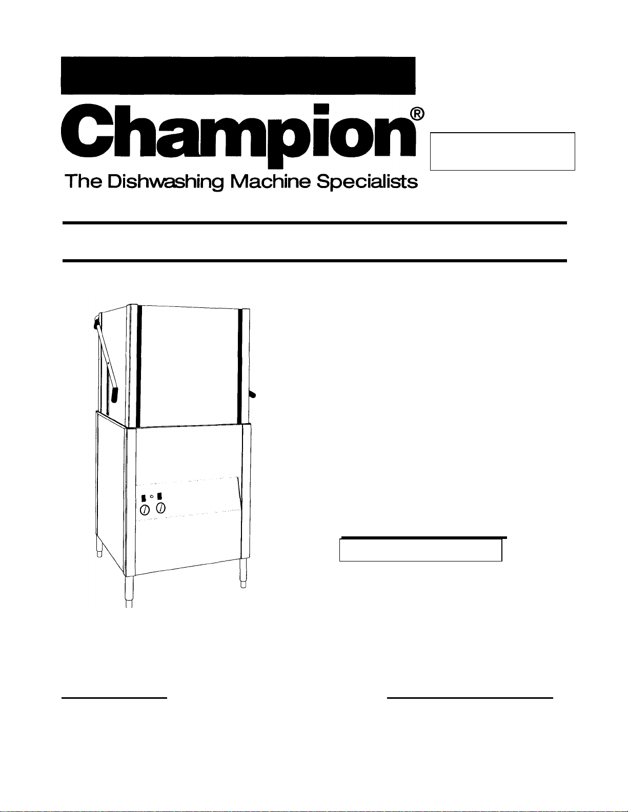
This manual supersedes PIN
112426, April, 1997. Destroy
previous edition.
For machines beginning with Technical Manual
serial no. 89519 and above
International Door
Dishwasher
Model
I-DHM 3
High Temperature
with Built-in Booster
Machine Serial No.
February, 1998__________________________Manual P/N 112426 Rev.A
P. 0. Box 4149 2674 N. Service Road
Winston-Salem, North Carolina 27115-4149 Jordan Station, Ontario, Canada LOR ISO
336/661-1556 Fax: 336/661-1660 905/562-4195 Fax: 905/562-4618
Champion Industries, Inc.
Page 2

Revision History
1
Revision
Date
1/30/98 All 89519 Issue of manual and
Revised Pages Serial Number
Effectivity
Comments
replacement parts lists
Page 3

CONTENTS
INTRODUCTION 6
Model Number 7
Standard Equipment 7
Options 7
Electrical Power Requirements 7
INSTALLATION 8
Unpack the Dishwasher 8
To Change from Straight -through Operation to Comer Operation 9
Electrical Connections 10
Plumbing Connections 12
Water Connections 12
Drain Connections 13
Chemical Connections 14
INITIAL START -UP 16
OPERATION 21
MAINTENANCE 23
Maintenance Schedule 23
Deliming Schedule 23
Troubleshooting 24
REPLACEMENT PARTS LIST 29
ELECTRICAL SCHEMATICS 59
LIST OF FIGURES
Figure 1 - Remove Front Panel 8
Figure 2 - Placement for Comer Operation 9
Figure 3 - Change the Track Assembly 9
Figure 4 - Electrical Connection Location 10
Figure 5 - Hinged Control Panel 11
Figure 6 - Main Terminal Block 11
Figure 7 - Hot Water Connection, 3/4" NPT 12
Figure 8 - Drain Connection, 1-1/2" OD 13
2
Page 4

LIST OF FIGURES (Cont'd)
3
Figure 9 - Detergent Signal Connection Point 14
Figure 10 - Detergent Probe Injection Point, 1/2" 15
Figure 11 - Rinse Aid Injection Point, 1/8" NPT 15
Figure 12 - Doors and Panels 30
Figure 13 - Door Guides, Stops, and Lift Bracket 32
Figure 14 - Door Handle, Spring Assembly and Safety Switch 34
Figure 15 - Track Assembly 36
Figure 16 - Wash/Rinse Spray Piping 38
Figure 17 - Wash/Rinse Spray Arm Assembly 40
Figure 18 - Drain Assembly and Scrap Screens 42
Figure 19 - Wash Tank Heat and Thermostats 44
Figure 20 - Electric Booster Assembly and Thermostats 46
Figure 21 - Fill Piping Assembly 48
Figure 22 - Pump Assembly 50
Figure 23 - Control Panel and Gauges 52
Figure 24 - Control Cabinet 54
Figure 25 - Dishracks and PRV 56
Figure 26 - Electrical Schematic (Electrical Heat 1 & 3 Phase) 59
Figure 27 - Electrical Schematic (Steam Heat 1 & 3 Phase) 60
Figure 28 - Electrical Schematic (Optional Timed Fill) (1 & 3 Phase) 61
Page 5

INTRODUCTION
6
Welcome to Champion...
and thank you for allowing us to take care of your
dishwashing needs.
This manual covers the international door-type dishwasher. Model I-DH. Your machine was
completely assembled, inspected, and thoroughly tested at our factory before it was shipped
to your installation site.
This manual contains:
• Installation Instructions
• Operation Instructions
• Maintenance Instructions
• Replacement Parts Lists
• Electrical Schematics
All information, illustrations and specifications contained in this manual are based upon the
latest product information available at the time of publication. Champion constantly
improves its products and reserves the right to make changes at any time or to change
specifications or design without notice and without incurring any obligation.
For your protection, factory authorized parts should always be used for repairs.
Replacement parts may be ordered directly from your Champion authorized parts
distributor or authorized service agency. When ordering parts, please supply the model
number, serial number, voltage, and phase of your machine, the part number, part
descriptions and quantity.
Page 6

Model Number
Power Requirement
The I-DH is a high temperature (180°F/82°C)
sanitizing dishwasher with booster.
Standard Equipment includes:
• Manual tank fill
• Built-in (40°F/23°C rise) electric or steam
booster heater.
• Field convertible for comer operation
• Electric tank heat (3 KW)
• Balanced door lift system
• Automatic start on close of doors
• Low -water tank heat protection
• 1HP drip-proof pump motor
• Door safety switch
• Splash-proof control console
• Interchangeable upper & lower spray arms
• Stainless steel front and side panels
• Detergent/chemical connection provisions
• Fill solenoid valve
• 3/4" line strainer
• Common utility connections
• Two dish racks (peg and flat bottom)
Options
Electric booster with (70°F/39°C temperature rise) heater
for (110°F/43°C) hot water supply.
Pressure reducing valve, (PRV) 3/4" - P/N 107550
Water pressure gauge (0-60 PSI) - P/N 100135
Electrical Power Requirements
Voltage
220/60/1 40°F/23°C 56A 70A
220/50/1 40°F/23°C 56A 70A
220/60/3 40°F/23°C 32A 40A
220/50/3 40°F/23°C 32A 40A
380/60/3 40°F/23°C 19A 24A
380/50/3 40°F/23°C 19A 24A
220/60/1 N/A — —
220/50/1 N/A — —
220/60/3 70°F/39°C 41A 52A
220/50/3 70°F/39°C 41A 52A
380/60/3 70°F/39°C 24A 30A
380/50/3 70°F/39°C 24A 30A
Booster Rise
Machine Full Load Amps
(125% Service Factor)
7
Page 7
INSTALLATION
8
Unpack the dishwasher
CAUTION:
Care should be taken when lifting the machine
to prevent damage.
NOTE:
The installation of your machine must meet
all applicable health and safety codes.
1. Immediately after unpacking the machine, inspect
for any shipping damage. If damage is found, save
the packing material and contact the carrier
immediately.
2. Remove the dishwasher from the skid. Move the
machine to its permanent location.
NOTE:
Refer to: To change from Straight-through
Operation to Corner Operation on the next page if
your machine will be placed for comer operation.
3. Level the machine (if required) by placing a level on
the top of the machine and adjusting the feet. Level
the machine front-to-back and side-to-side.
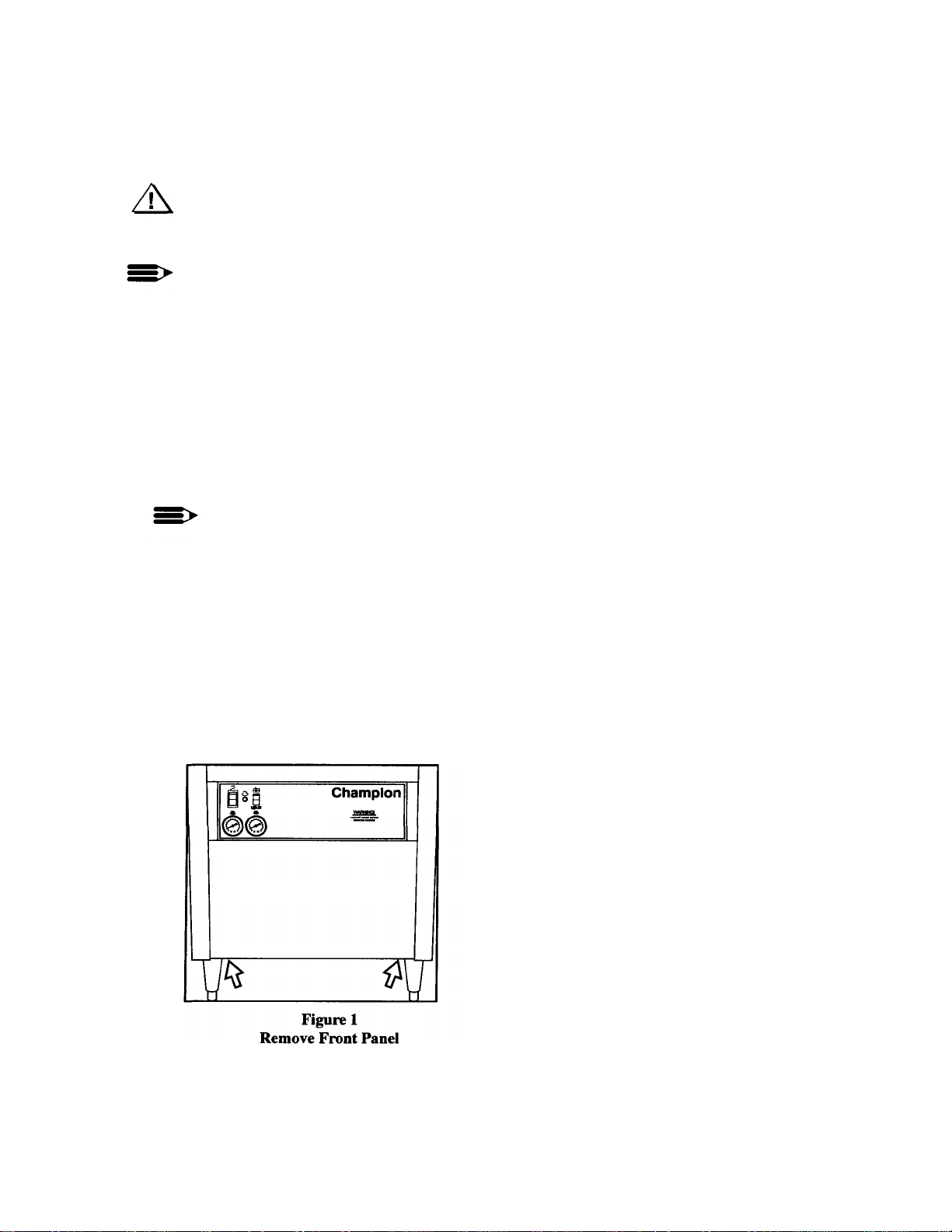
4. Remove the dishracks from the interior of the
machine.
5. Refer to Fig. 1. Remove (2) screws that hold the
front panel. Remove the front panel in preparation
for service connections.
Page 8
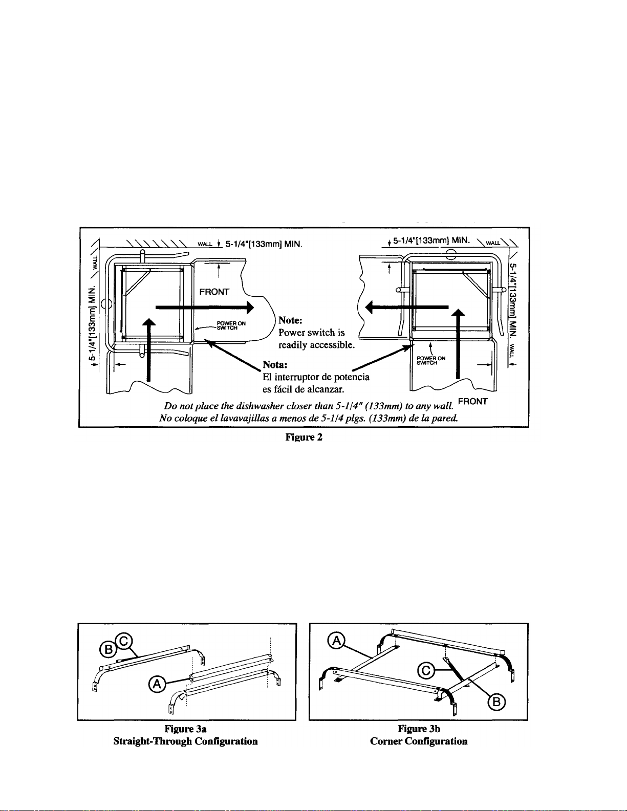
To Change from Straight -through
Operation to Corner Operation
The I-DH dishwasher is shipped from the factory for
straight-through operation. The following instructions
explain how to change the dishwasher for comer
operation. Refer to Fig. 2
1. Place the dishwasher so that operator controls
are readily accessible.
2. Minimum clearance from any wall is 5-1/4"
(133mm).
Placement for Corner Operation
Refer to Fig. 3a-3b and perform the steps below.
1. Remove the front rack guide (A). Discard the
square spacers.
2. Move front rack guide (A) to the left side of the
rack tracks. (See Fig. 3b) Use existing hardware.
3. Unbolt the track (B) and rack support rod (C).
4. Remove and save the two remaining fasteners
from rear track.
5. Bolt (B) and (C) as shown in Fig. 3b.
Figure3
Change the Track Assembly
9
Page 9
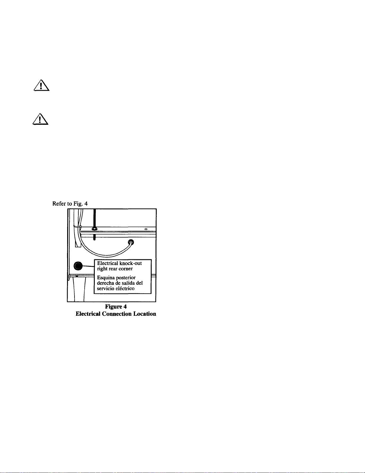
INSTALLATION (Cont)
Electrical Connections
Warning:
Electrical and grounding connections must
comply with all applicable Electrical Codes.
Warning:
When working on the dishwasher, disconnect the
electric service and place a tag at the disconnect
switch to indicate work is being done on that
circuit.
1. A qualified electrician must compare the
electrical power supply with the machine
electrical specifications before connecting to the
incoming service through a fused disconnect
switch.
2. A knock -out is provided at the lower right rear
comer for the electrical service connection. A
fused disconnect switch or circuit breaker
(supplied by others) is required to protect
the power supply circuit.
10
Page 10
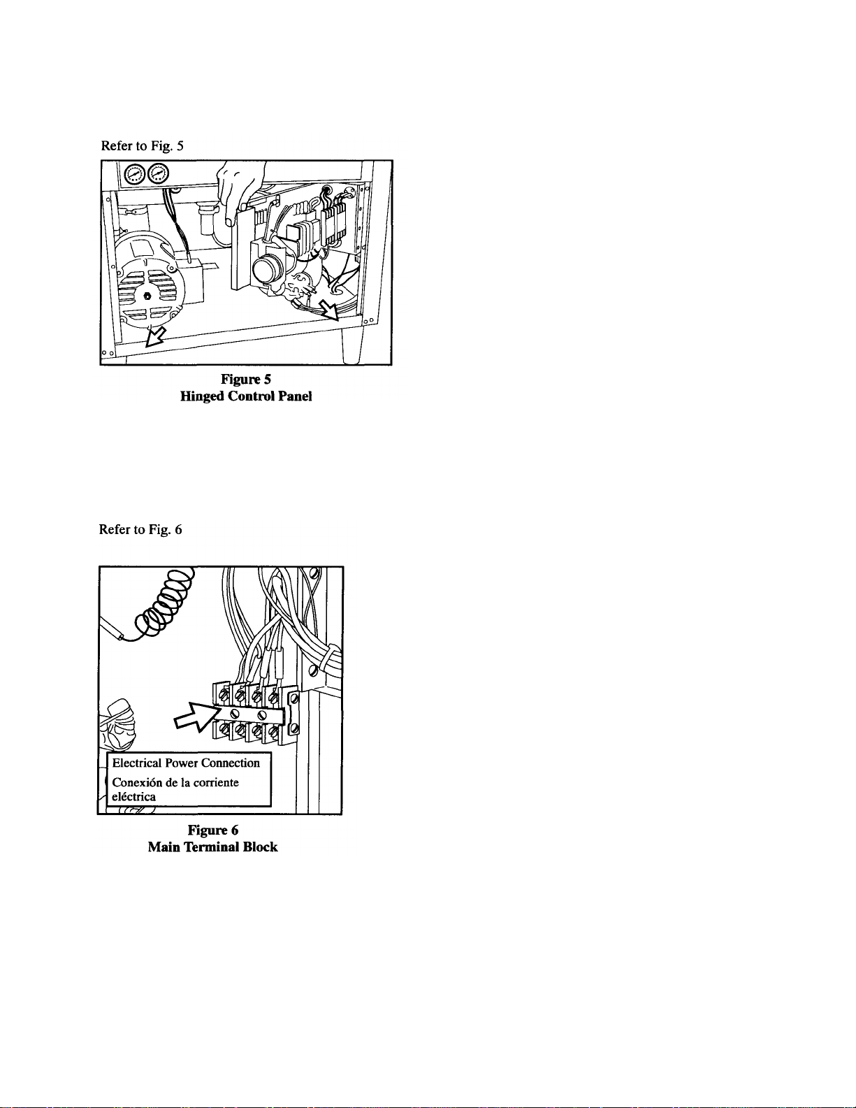
Electrical Connections (Cont.)
3. Remove (2) lower screws from the front panel of the
machine to expose the electrical controls. Remove (2)
screws on the control panel support. Swing the hinged
control panel forward.
4. Three phase or single phase incoming power wiring
connections are made at the bottom of the
machine's main terminal block. The main terminal
block is located on the side of the front right post of
the dishwasher.
11
Page 11
INSTALLATION (Cont.)
12
Plumbing Connections
NOTE:
Plumbing connections must comply with all
applicable sanitary and plumbing codes.
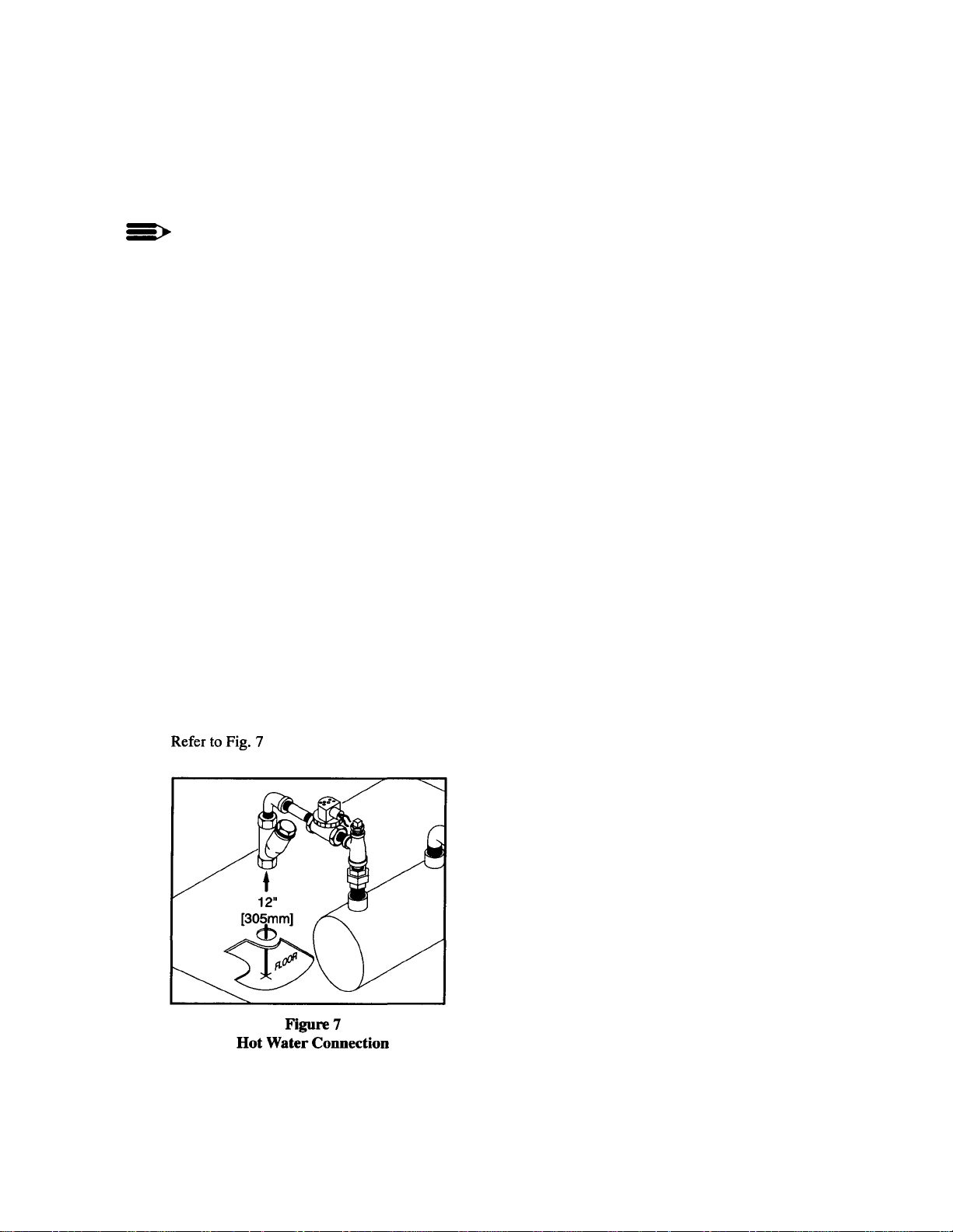
Water Connections
1. The I-DH dishwasher requires a single, hot
water supply. The following minimum water
temperatures are recommended:
I-DH with built -in 40° rise electric booster
(Minimum 140°F/60°C)
(Min./Max. flow pressure 20-22 PSI/138 kPa)
I-DH with built -in 70° rise electric booster
(Minimum 110°F/43°C)
(Min./Max. flow pressure 20-22 PSI/138 kPa)
2. Install a pressure reducing valve, (PRV), in the
water supply line if flow pressure exceeds 2022PSI/138-151.8kPa.
3. The hot water connection to all I-DH
dishwashers is 3/4" NPT. The connection is
made from underneath the dishwasher up to the
hot water solenoid valve located on the left side
of the booster tank.
3/4" NPT
Page 12
Water Connections (Cont.)
4. A manual shut-off valve (supplied by others)
should be installed in the supply line in order
to service the machine.
5. A pressure reducing valve, (PRV), (supplied
by others) should be installed in the water
supply line.
6. A pressure gauge (supplied by others) should
be installed in the water supply line on the
machine side of the PRV.
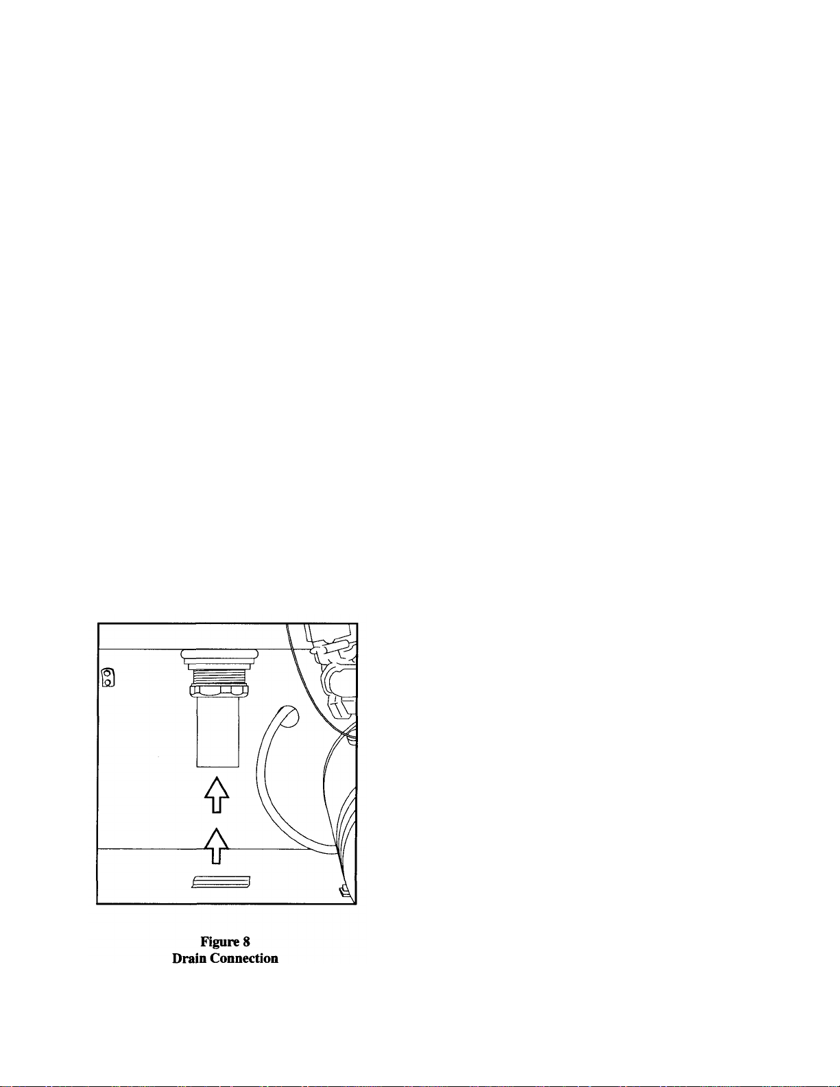
Drain Connections
1. The model I-DH is a GRAVITY DRAIN
machine equipped with a 1-1/2" O.D. hose
connection point.
2. Drain height for model I-DH must not exceed
11" (280mm) above floor level.
3. The drain connection is made to the
dishwasher from underneath the machine
through an access hole in the machine base.
Refer to Fig. 8
1-1/2" O.D.
13
Page 13
INSTALLATION (Cont.)
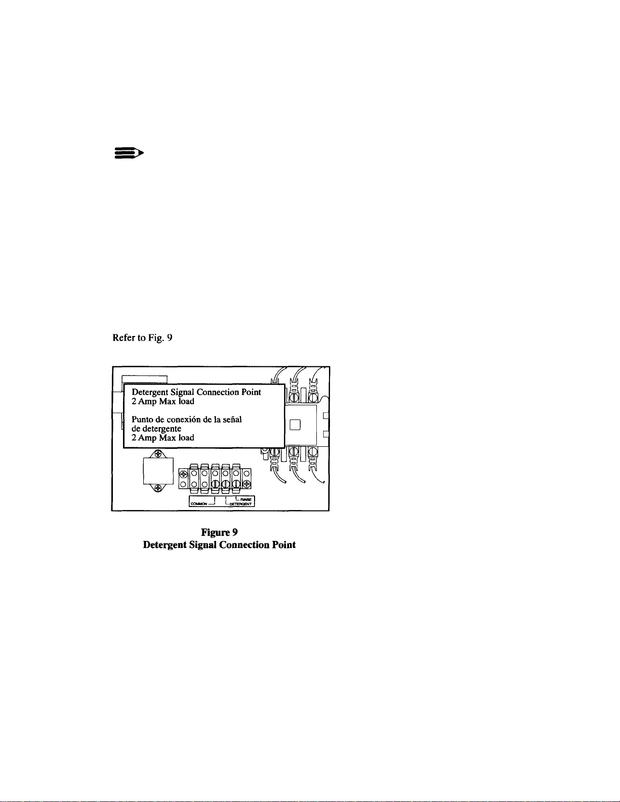
Chemical Connections
NOTE:
Consult a qualified chemical supplier for
your chemical needs.
1. An electrical detergent signal connection point
for detergent dispensing equipment is provided
on the control voltage terminal block located in
the top left comer of the hinged control panel.
2. The detergent signal is limited to a maximum
load of 2 Amps. Signal voltage is 120VAC.
14
Page 14
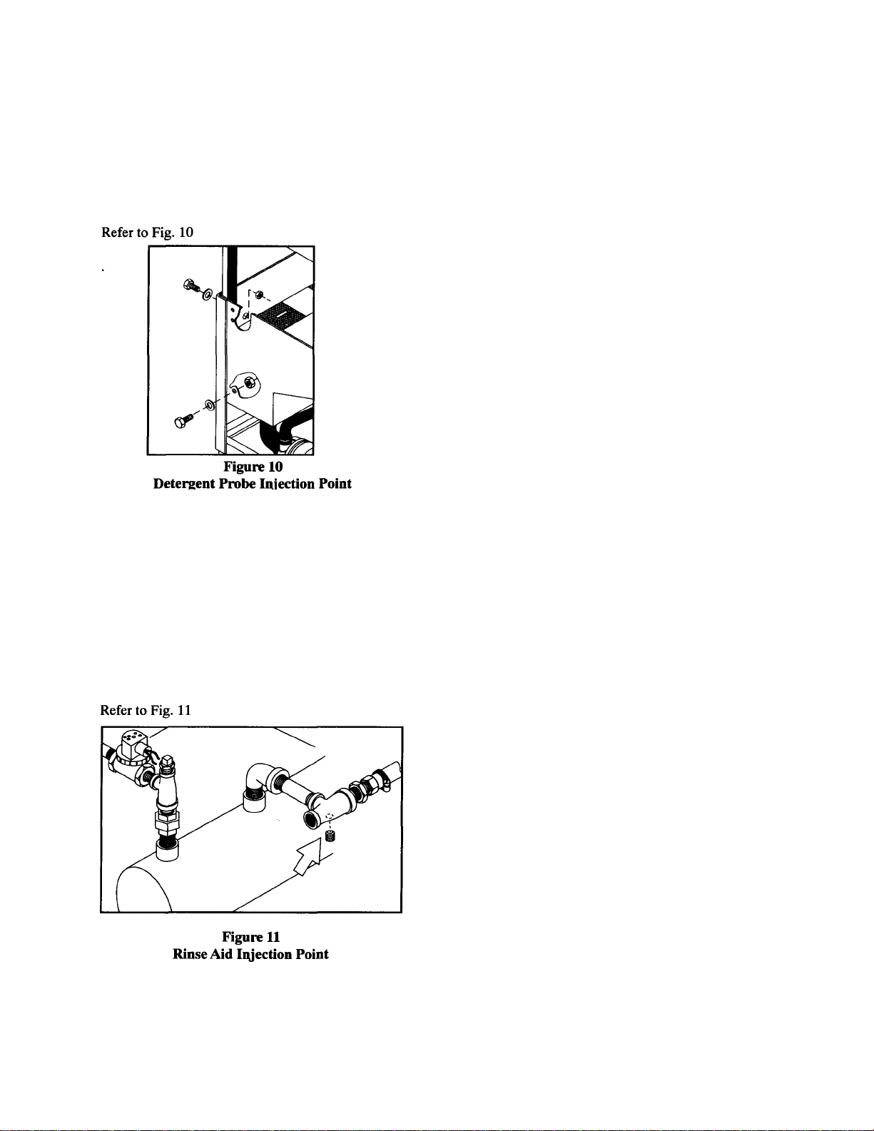
Chemical Connections (Cont.)
3. A 1/2" detergent probe injection point is
provided at the rear and left side of the
dishwasher.
1/2" Plug
4. A 1/8" NPT rinse aid injection point is provided in
the final rinse manifold of the booster piping. The
manifold is located on the right side of the booster
assembly. It can be accessed from the front of the
dishwasher.
1/8" NPT
15
Page 15
INITIAL START-UP
Complete the installation
After plumbing and electrical connections are made, follow the
steps below to complete the installation of your dishwasher.
1. Remove the white protective covering from the exterior of
the machine.
2. Remove any foreign material from inside the
machine.
3. Make sure dishwasher power switch is off.
4. Turn main water supply on.
5. Turn main power on at the main power service
disconnect switch.
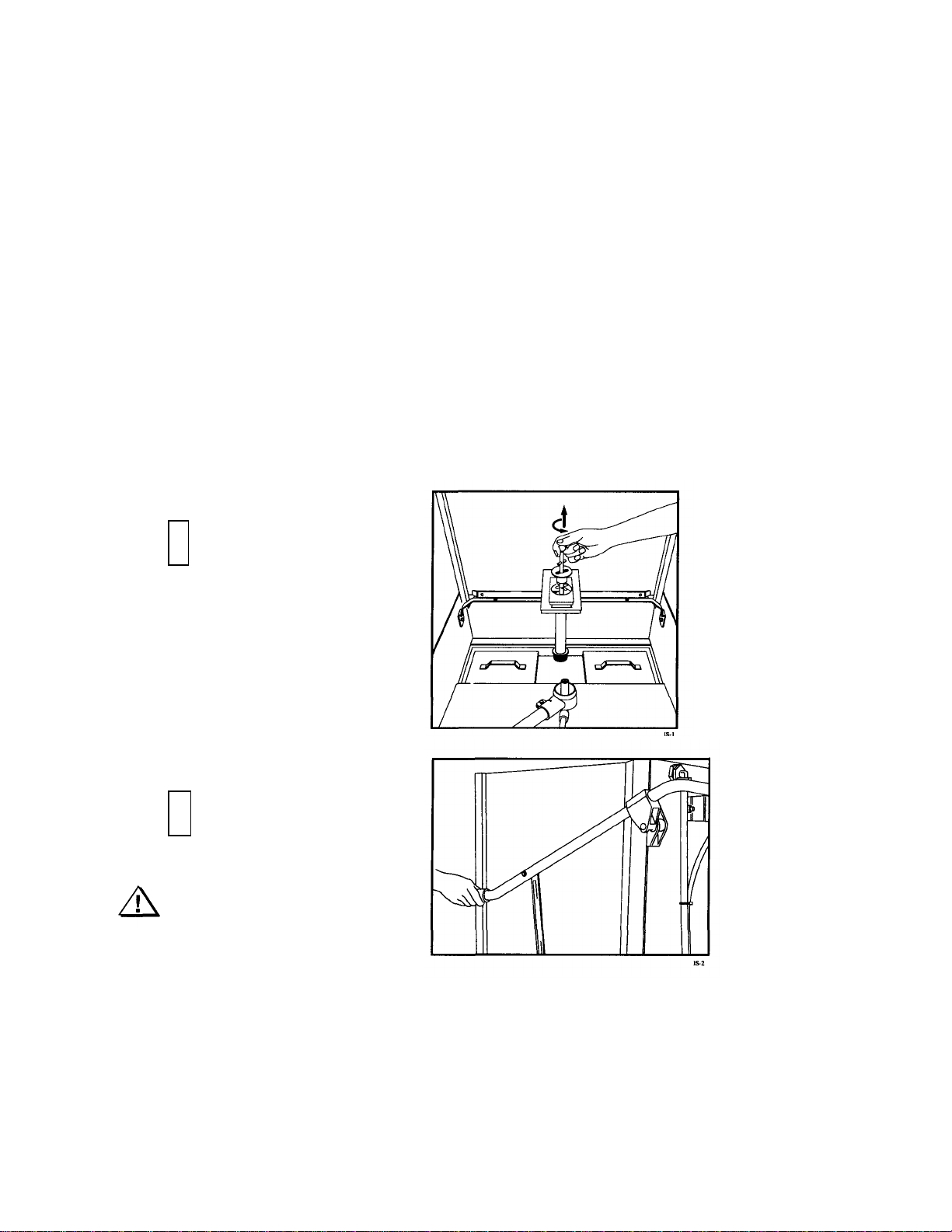
Fill the dishwasher with water
Follow the steps below to fill your machine for the first
time and each time the machine is completely drained.
1
Install scrap screens. Make
sure rubber stopper is secure
on the drain-overflow
assembly. Make sure the
drain-overflow seats securely
in the tank bottom.
16
2
Make sure all doors are
fully closed.
Warning:
During the fill operation,
water will spray from the
dishwasher if the doors are
open.
MAKE SURE DOORS
ARE FULLY CLOSED.
Page 16
Fill the dishwasher
with water (Cont.)
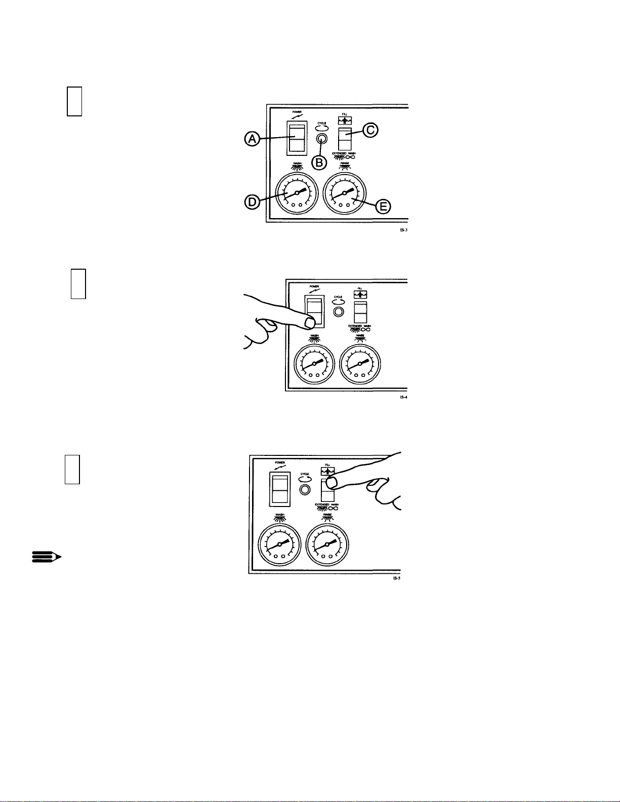
3
The controls are located on the
front of the dishwasher.
A- On/Off power switch
B- In cycle light
C- Fill/Extended wash
switch D-Wash water
temperature gauge
E- Final rinse water
temperature gauge
4
THE POWER SWITCH IS OFF
DURING INITIAL FILL.
Push the On/Off power switch
down to the OFF position. The
red indicator light in the center
of the power switch is not
illuminated when the switch is
off.
5
Push and hold the Fill/Extended
wash switch UP to the FILL
position to fill the dishwasher
with water.
NOTE:
The initial fill primes the
booster tank assembly. The
booster tank is full when you
hear water enter the wash tank
of the dishwasher.
Continue to hold the switch UP
until water begins to drain out
the overflow. Tank is full.
Release the Fill/Extended wash
switch.
17
Page 17

INITIAL START-UP (Cont.)
Check wash and final rinse
water temperatures
6
Push the On/Off power switch "Up" to the on
position. The red indicator light in the switch will
come on.
The wash tank and booster tank heaters will begin to
heat the water in the dishwasher.
7
Wait approximately 10 minutes for the wash tank
water to reach operating temperature.
Check the wash water temperature gauge located on
right side of the control cabinet to be sure it indicates
the proper temperature.
8
Open and then fully close the dishwasher doors. The
dishwasher will begin a wash cycle automatically.
Note that the amber colored cycle lamp is lit during
the automatic dishwasher cycle.
Opening the doors anytime during the cycle will stop
the dishwasher.
Closing the doors will resume the
automatic cycle where it left off.
18
Page 18

Check the wash and final rinse
water temperatures (Cont.)
9
The final rinse water temperature should be a
minimum of 180°F/82°C during the final rinse
cycle. The optimum final rinse temperature is 180195°F/82-91°C.
Check the final rinse water temperatur e gauge
located on left side of the control cabinet
Check the Extended Wash
operation
The extended wash switch holds the
dishwasher in a continuous wash mode for
cleaning heavily soiled ware.
10
Open and then fully close the dishwasher doors. The
dishwasher will begin a wash cycle automatically.
Push the Fill/Extended wash switch "Down" to the
extended wash position.
The dishwasher will remain in a continuous wash
mode until the switch is flipped back to the center
position.
NOTE:
The extended wash switc h may also be
used during deliming operations.
Consult a qualified chemical supplier
for detailed instructions and
procedures.
19
Page 19

INITIAL START-UP (Cont.)
Complete the initial start -up
Check all the plumbing for leaks. Also, check the
drain plumbing for leaks and be sure that the drain
will handle the drain water flow from the dishwasher.
After the drain and the plumbing connections are
checked, turn off the power to the dishwasher.
Drain the dishwasher
11
Turn off power at the dishwasher. Drain the dishwasher by pulling the handle of the drain-overflow
assembly straight up.
Be sure that the drain-overflow rubber stopper is
secure on the drain-overflow assembly pipe.
Check that the building drain handles the water flow
exiting the dishwasher drain.
20
12
Remove the scrap screens and check the drain
located in the bottom of the dishwasher wash tank.
Clean the interior of the wash tank of any foreign
material.
Leave the doors open to air dry the interior of the
dishwasher.
The initial start-up is complete.
Page 20

OPERATION
Refer to the Initial Start-up section. Steps 1-5, on pages 16-20, to place your dishwasher into service. To operate your
dishwasher, perform the action in the left hand column; check the result in right hand column.
Action Result
1. Push the On/Off power switch "UP" to the ON
position.
1. The indicator light in the center of the power switch
illuminates. The wash tank heater and the booster tank
heater begin to heat.
2. Wait approximately 10 minutes for the wash tank
heater to heat the water. Then, check the reading on
the wash water temperature gauge.
3. Prescrap and load the ware into the dishrack. 3. Ware should be placed edgewise in the peg rack. Cups and
4. Open the doors. Insert a dishrack
of soiled ware. Fully close the
doors.
Opening the doors anytime during the
automatic cycle stops the dishwasher.
Closing the doors will resume the cycle
where it left off.
5. Check the final rinse temperature gauge reading
during the 10 second final rinse cycle.
2. The wash water temperature gauge should indicate a
minimum of 150°F/66°C.
bowls should be placed upside down in the flat rack.
Silverware should be spread evenly in a single layer in the
flat rack.
4. Amber cycle light illuminates as the dishwasher begins a
60 second automatic cycle. The cycle times are listed
below:
Wash = 48 seconds Dwell = 2
seconds Final rinse = 10 seconds
5. The final rinse temperature gauge should indicate a minimum
of 180°F/82°C. The optimum final rinse temperature range is
between 180-195°F/82-90°C.
6. Check the incoming water pressure during the 10
second final rinse cycle. A water pressure gauge
(supplied by others) should be installed on the
incoming water supply.
7. The 60 second automatic cycle ends. 7. The amber cycle light goes out.
8. Open the doors. Remove the clean rack. Insert
another rack of soiled ware. Fully close the doors.
9. Turn power OFF at the dishwasher. Remove the
drain-overflow assembly. Clean the scrap screens.
Clean the dishwasher after each meal period or
every two hours of operation.
6. The water pressure gauge should indicate a flowing pressure
of 20-22 PSI/138-151.8 kPa. A pressure reducing valve
(PRV) is required if flow pressure exceeds 20-22 PSI/138-
151.8 kPa
8. The 60 second automatic cycle begins again.
9. Dishwasher wash tank drains completely. Periodic cleaning
reduces detergent consumption and improves washing
results.
21
Page 21

MAINTENANCE
Cleaning your machine is the best maintenance that
you can provide. Components that are not regularly
flushed and cleaned do not perform well.
The following schedules are the minimum requirements necessary for the proper performance of your
machine. Intervals should be shortened whenever
your machine is faced with abnormal working
conditions, hard water, or multiple shift operations.
CLEANING SCHEDULE
Every 2 Hours or After Each Meal Period
1. Drain the dishwasher.
2. Flush interior with fresh water.
3. Clean scrap screens and pump intake screen.
4. Clean spray arm nozzles.
Every 8 Hours or at the End of the Day
1. Drain the machine.
2. Flush interior with fresh water.
3. Clean scrap screens and pump intake screen.
4. Clean spray arms.
5. Thoroughly clean the exterior of machine.
DO NOT HOSE DOWN WITH WATER.
6. Reassemble the machine.
7. Leave doors open to aid in drying.
CAUTION:
Do not leave water in wash tank
overnight.
DELIMING SCHEDULE
Your dishwasher should be delimed regularly to
prevent buildup of mineral deposits.
NOTE:
Consult your chemical supplier for an
appropriate deliming solution and proper
procedures.
23
Page 22

TROUBLESHOOTING
Wash motor not running
Incoming water temperature at machine
24
Perform the seven checks listed below in the event that your dishwasher does not operate as
expected.
1. All switches are ON
2. Drain-overflow assembly is in place and seated
3. Wash and rinse nozzles are clean
4. Wash and rinse pipe assemblies are installed correctly
5. Scrap screens are properly positioned
6. Thermostat(s) are properly adjusted
7. Detergent and rinse additive dispensers are adequately filled.
If a problem still exists, use the following table for troubleshooting.
CONDITION CAUSE SOLUTION
Machine will not start
Machine washes
constantly
Low or no water
Continuous water filling
Wash tank water
temperature is low
when in use
Doors not closed Make sure doors are fully closed
Door safety switch faulty Contact your service agency
Start switch faulty Contact your service agency
Main switch off Check disconnect at main panel
Overload protector tripped Reset overload in Control Box
Fill/Extended wash switch in
extended wash position
Main water supply is turned off Turn on house water supply
Drain-overflow assembly is not
in place and seated
Machine doors not fully closed Close doors securely
Faulty fill valve Contact your service agency
Machine not filled initially Hold fill switch UP to fill
Clogged strainer in fill valve Clean or replace
Stuck or defective fill switch Contact your service agency
Fill valve will not close Clean or replace
Drain-overflow not in place Install drain-overflow assembly
Overload protector tripped Reset overload in Control Box
Defective motor Contact your service agency
too low
Defective thermometer Check or replace
Defective thermostat Check for proper setting or replace
Defective heater element Check or replace
Defective solenoid valve Check or replace
Heater elements have soil/lime buildup Clean and delime
Push Fill/Extended wash switch
to the center position
Place and seat drain-overflow
Raise temperature to:
110-140°F/43-60°C
Page 23

TROUBLESHOOTING (Cont.)
Insufficient final rinse or
25
CONDITION
Insufficient pumped
spray pressure
no final rinse
Low final rinse
temperature
Poor washing results
CAUSE SOLUTION
Clogged pump intake screen Clean
Clogged spray pipe Clean
Scrap screen full Must be kept clean and in place
Low water level in tank Check drain-overflow assembly
Pump motor rotation incorrect
Defective pump seal Contact Service Agent
Faulty pressure reducing valve Clean or replace
Improper setting on pressure reducing
valve
Clogged rinse nozzle and/or pipe Clean
Improper water line size Have installer change to proper size
Clogged strainer in fill valve Clean or replace
Low incoming water temperature
Defective thermometer Check for proper setting or replace
Detergent dispenser not operating
properly
Insufficient detergents Contact detergent supplier
Wash water temperature too low
Wash arm clogged Clean
Improperly scraped dishes Check scraping procedures
Ware being improperly placed in rack Use proper racks Do not overload racks
Improperly cleaned equipment
Heater elements have soil/lime buildup Clean and delime
Reverse connection between L1 and L2 in
Control Cabinet
Set flow pressure at 20-22 PSI/ 1381518kPa
Check the booster - be sure the thermostat
is set to maintain 180°F/82°C temperature
Check valve to be sure it is clean and
operating
Contact detergent supplier
See condition "Wash Tank Water
Temperature" above
Unclog wash sprays and rinse nozzles to
maintain proper pressure and flow
conditions Overflows must be open Keep
wash water as clean as possible
Page 24

30
Figure 12
Doors and Panels
Page 25

DOORS AND PANELS
31
Fig 12
Item No
Part No Part Description Qty
1 0709405 DOOR, SIDE 2
2 0709402 FRONT DOOR, DOOR MACH 1
3 321929 RH PANEL NO CUT OUT 1
4 321933 PANEL INSTRUMENT 1
5 112389 DECAL, CONTROL PANEL 1
6 322074 PANEL, FRONT LOWER 1
7 321941 LH PANEL W/CUTOUT 1
8 108418 PLUG PLASTIC 2
9 109034 WASHER 13/16 X 1 13/16 FIBER 2
10 108417 NUT, PLASTIC 2
11 100779 SCREW, 1/4-20 X 5/8 TRUSS HEAD 6
12 0504822 SCREW, 8-32 X 1/2 PAN HEAD 4
13 100763 SCREW, 10-32 X 1 ROUND HEAD 2
14 0501873 FOOT, CAST GREY 4
Page 26

32
Page 27

DOOR GUIDES, STOPS, AND LIFT BRACKET
Fig 13
Item No
Part No Part Description Qty
1 108053 PLUG, CORNERPOST 2
2 107966 NUT, GRIP 10-32 W/INSERT 8
3 0309277 BRACKET, DOOR LIFT 1
4 100097 SCREW 10-32 X 1/2" TRUSS HEAD 2
5 108347 GUIDE, DOOR 6
6 108410 GASKET, DOOR GUIDE (26") 12
7 107970 SCREW 8-32 X 1 FILISTER 36
8 100007 SCREW 10-32 X 3/8 TRUSS HEAD 2
9 0307328 STOP, DOOR 2
33
Page 28

34
Page 29

DOOR HANDLE, SPRING ASSEMBLY, AND SAFETY SWITCH
Fig 14
Item No
10 107420 NUT, PLAIN M6 6
11 107436 SCREW M6 X 16MM FILISTER 8
12 107399 SUPPORT, PIVOT BLOCK 2
13 108368 GASKET, BACKING 2
14 304811 PLATE, BACKING 2
15 100740 BOLT 5/16-18 X 1 HEX HEAD 2
16 107966 NUT, GRIP 10-32 W/NYLON INSERT 8
17 322077 GUARD, SPLASH 2
18 100097 SCREW 10-32 X 1/2 TRUSSHEAD 8
19 0509264 BUSHING, SIDE DOOR 2
20 0509274 NUT, ACORN 5/16-18 SST 2
21 0309167 LIFT BAR, DOOR 2
22 102376 WASHER, FLAT 2
23 104002 BOLT 5/16-18 X 1-1/2 2
24 100154 NUT, PLAIN 5/16-18 4
25 106013 WASHER, LOCK 5/16 SPLIT 2
26 102376 WASHER 5/16 X 3/4 X 1/16 4
27 321927 SPRING ANCHOR BRACKET 1
28 0509199 SWITCH, DOOR SAFETY 1
29 0309451 BRACKET, SWITCH 1
30 107967 NUT, GRIP (1/4-20 with nylon insert) 2
Part No Part Description Qty
1 0509168 BOLT 5/16-18 X 11 HEX HEAD 2
2 108066 SPRING, EXTENSION 2
3 107397 BLOCK, SPRING HOOK 2
4 0509166 DOOR HANDLE 1
5 107437 BOLT M6 X 45MM HEX HEA D 4
6 107396 BLOCK, UPPER PIVOT 2
7 107393 PIN, PIVOT 2
8 107962 HANDLE, GRIP 2
9 107395 BLOCK, LOWER PIVOT 2
35
Page 30

36
Page 31

TRACK ASSEMBLY
Fig
15
Item No
Part No Part Description Qty
1 0309469 GUIDE, RIGHT HAND 1
2 0309472 TRACK, REAR 1
3 0309468 GUIDE, LEFT HAND 1
4 0309470 SUPPORT, RACK 1
5 0309471 TRACK, FRONT 1
6 106727 SCREW (10-32 X 5/8 FLAT HD) 6
7 107966 NUT, GRIP (10-32 W/NYLON INSERT) 6
8 100779 BOLT (1/4 -20 X 5/8 TRUSS HD) 8
9 106482 WASHER, LOCK 8
10 100003 NUT (1/4-20 HEX HD) 8
11 0309473 SPACER 2
37
Page 32

38
Page 33

WASH/RINSE SPRAY PIPING
39
Fig 16
Item No
Part No Part Description Qty
1 0309444 RINSE TUBE 1
2 0509181 FITTING, STRAIGHT COMPRESSION 2
3 0509150 CONNECTOR, TOP RINSE 1
4 0509180 FITTING, STRAIGHT COMPRESSION 2
5 0309445 RINSE TUBE, TOP 1
6 0509179 FITTING, BULKHEAD 1/2"NPT 1
7 0507445 SPINDLE, WASH ARM 2
8 109864 SUPPORT, WASH ARM 2
9 0509178 CONNECTOR, BOTTOM RINSE 1
10 109781 STANDPIPE, WASH 1
11 100736 BOLT 1/4-20 X 3/4 HEX HEAD 2
12 107967 NUT, GRIP 1/4-20 1
13 106482 WASHER, SPLIT LOCK SST 2
14 0309350 WASHER 1
Page 34

40
Page 35

WASH/RINSE SPRAY ARM ASSEMBLY
Fig 17
Item No
1 0507443 SPINDLE, RINSE ARM 2
2 0508376 NOZZLE, RINSE ARM 12
3 112164 BEARING, RINSE ARM 4
4 0707453 RINSE ARM ASSY (Includes 2 & 3) 2
5 0507444 NUT, RINSE ARM 2
6 109835 SCREW (#8 X 1/2 PAN HD) 4
7 0707452-S WASH ARM ASSY (Includes 6 & 8) 2
8 0507446 BEARINGWASH ARM 2
0707450 RINSE ARM (Does not include items 2, 3 or 9)
0707456 WASH ARM (Does not include item 8)
Part
No
Part Description Qty
41
Page 36

42
Page 37

DRAIN ASSEMBLY AND SCRAP SCREENS
43
Fig 18
Item No
1 112393 KNOB, DRAIN LIFT 1
2 112394 ROD ASSY, DRAIN LIFT 1
3 112392 GUIDE, DRAIN LIFT 1
4 100097 SCREW (10-32 X 1/2" TRUSS HD) 2
5 322159 RETAINER, OVERFLOW 1
6 321939 FILLER, DRAIN PLATE (retained by spring clip) 1
7 322120 FILLER, DRAIN PLATE (retained by stud and nut) (Not shown) 1
8 100194 NUT, GRIP (10-32 SST) 2
9 100141 NUT, GRIP (1/4-20 SST) 1
10 322006 TUBE, OVERFLOW 1
11 107680 SEAT RUBBER, OVERFLOW TUBE 1
12 205813 DRAIN BASKET, MODIFIED 1
13 112044 SLIP NUT 1
14 112045 WASHER/TAILPIECE 1
15 107473 TAILPIECE 1
16 305164 SCREEN, SCRAP 2
Part No Part Description Qty
Page 38

44
Page 39

WASH TANK HEAT AND THERMOSTATS
45
Fig 19
Item No
1 108391 THERMOMETER 4 FT 1
2 109069 THERMOSTAT W/CAP 110-220%F 1
3 201041 WASHER 3
4 201029 NUT, LOCK 1/2" 3
5 322076 DUAL THERMOSTAT BRACKET 1
6 110561 THERMOSTAT, FIX ED HIGH LIMIT 1
7 106482 WASHER, LOCK 1/4 SPLIT SST 4
8 100003 NUT, PLAIN 1/4-20 SST 4
9 100740 BOLT 5/16-18 X 1 HEX HEAD 4
10 108345 GASKET 3X3X1/8 2" 1
11 102376 WASHER 5/16 X 3/4 X 1/16 8
12 106013 WASHER, LOCK 5/16 SPLIT 4
13 100154 NUT, PLAIN 5/16-18 SST 4
14 0509185 HEATER 3KW 208-240V/380-415V 1/3PH 1
15 100007 SCREW 10-32 X 3/8 TRUSS HEAD 4
16 107966 NUT, GRIP 10-32 W/NYLON INSERT 4
— 104889 PUTTY, SEALING (USED TO SEAL ITEMS 3 & 4) A/R
Part No Part Description Qty
Page 40

46
Figure 20
Electric Booster Assembly and Thermostats
Page 41

ELECTRIC BOOSTER ASSEMBLY AND THERMOSTATS
47
Fig 20
Item No
1 100740 BOLT 5/16-18 X 1 HEX HEAD 2
2 102376 WASHER, FLAT 5/16 X 3/4 X 1/16 2
3 108954 NUT, GRIP 6-32 W/INSERT 2
4 110562 THERMOSTAT, HIGH LIMIT 1
5 109069 THERMOSTAT, BOOSTER 1
6 100003 NUT, PLAIN 1/4-20 SST 3
7 106482 WASHER, LOCK 1/4 SPLIT 3
8 107909 HEATER 6KW 208-240V, (Wired delta) 40°Rise (1 & 3 phase) 1
9 111334 HEATER 12KW 208-240V, (Wired delta) 70°Rise (3 phase) 1
10 109985 SEAL, ELECTRIC HEATER 1
11 100210 PLUG 1/8 SST 1
12 0509042 TANK, BOOSTER 1
Part No Part Description Qty
110563 COMPOUND, HEAT SINK A/R
107909 HEATER 6KW 380-415V (Wired wye) 40°Rise (3 phase only) 1
111334 HEATER 12KW 380V -415V, (Wired wye) 70°Rise (3 phase) 1
Page 42

48
Page 43

FILL PIPING ASSEMBLY
Fig 21
Item No
1 110768 LINE STRAINER BRASS 1
2 102444 STREET ELL 3/4" NPT BRASS 2
3 102651 NIPPLE 3/4" x 2" BRASS 1
4 111437 VALVE 3/4" NPT HOT WATER 1
5 100184 NIPPLE 3/4" NPT 3
6 102525 TEE 3/4" X 1/2" X 3/4" BRASS 1
7 100571 UNION 3/4" NPT BRASS 1
8 102504 PLUG, 1/2" NPT BRASS 1
9 102489 NIPPLE, 3/4" NPT X 2-1/2" BRASS 1
10 0308728 TEE, MODIFIED 3/4" X 1/2" X 3/4" X 1/8" BRASS 1
11 100392 BUSHING REDUCER 3/4" X 1/2" BRASS 1
12 107419 BARB, HOSE 1/2 NPTX 1/2 HOSE 1
13 105994 CLAMP, HOSE 2
14 107417 HOSE, 1/2" ID 9ft
15 102438 ELBOW, STREET 1/2" NPTX 90° BRASS 1
16 101259 PLUG, 1/8" NPT, BRASS 1
17 108516 COIL, SOLENOID VALVE (120V) 1
18 109903 KIT, REPAIR, 3/4" SOLENOID VALVE 1
Part No Part Description Qty
49
Page 44

Figure 22
Pump Assembly
50
Page 45

PUMP ASSEMBLY
51
Fig 22
Item No
1 308005 STRAINER 1
2 107966 NUT, GRIP 10-32 W/NYLON INSERT 1
3 104203 CLAMP, HOSE 2
4 104165 CLAMP, HOSE 1
5 107340 CLAMP, HOSE 1
6 112383 HOSE PUMP DISCHARGE 1
7 109562 HOSE, SUCTION 1
8 100734 BOLT 1/4-20 X 1/2" HEX HEAD 1
9 106482 WASHER, LOCK 1/4" SPLIT 1
10 110247 NUT, HEX JAM 7/16-20 1
11 110248 WASHER, FLAT 1
12 107463 PLUG 1/4" 1
13 107137 BOLT 10-32 X 7/8 HEX HEAD 11
14 100194 NUT, GRIP (10-32) 11
15 109651 VOLUTE 1
16 111143 IMPELLER 1
17 109653 GASKET, 0-RING 1
18 111111 PUMP SEAL 1
19 109649 BACK PUMP HOUSING 1
20 107690 NUT, JAM 3/8-16 4
21 106407 WASHER, LOCK 3/8" SPLIT 4
22 204460 BACKING PLATE, MACHINED 1
23 109654 PUMP SLINGER WASHER 1
24 110734 STUD 3/8-16 X 1 3/8 4
25 0509174 MOTOR 14HP (220/380-415V/50-60/3) 1
26 100739 BOLT 5/16-18 X 3/4 HEX HEAD 4
27 102376 WASHER, FLAT 5/16 4
28 106013 WASHER, LOCK 5/16-18 SST 4
29 100142 NUT, GRIP 5/16-18 4
30 100754 SCREW, FLAT 10-32 X 1/2" 4
31 110270 WASHER, COUNTERSUNK SST 4
— 0709191
— 0709279
Part No Part Description Qty
112163 MOTOR 14HP (220/380V/50-60/1) 1
109645 KIT, PUMP (INCLUDES 15,17,19) 1
PUMP/MOTOR ASSEMBLY
Complete 14HP(220V/380-415V/50-60/3ph)
PUMP/MOTOR ASSEMBLY
Complete 14HP(220V/380V/50-60/1ph)
1
1
Page 46

52
Page 47

CONTROL PANEL AND GAUGES
Fig 23
Item No
1 111980 CIRCUIT BREAKER, SWITCH, ON-OFF (5A) 1
2 112391 LITE, AMBER (IN-CYCLE) 1
3 0509228 SWITCH, ROCKER (FILL-EXTENDED WASH) 1
4 112521 SWITCH, MOMENTARY (OPTIONAL TIMED FILL ONLY) 1
5 108391 THERMOMETER, 4 FT 2
6 112086 OVERLAY, WASH 150°F 1
7 112090 OVERLAY, FINAL RINSE 180-195°F 1
8 112389 DECAL, CONTROL PANEL 1
Part No Part Description Qty
53
Page 48

Figure 24
Control Cabinet
54
Page 49

CONTROL CABINET
55
Fig 24
Item No
1 0501379 Switch, timer 4
2 0508773 Motor, timer 1
3 0709632 Assembly, timer (includes Items 1, 2, 4) 1
4 0503701 Bearing, timer 1
5 111277 Transformer (120V : 24V) 1
6 111904 Contactor, booster heater (40A, 3 pole) 1
7 111904 Contactor, wash tank heater (40A, 3 pole) 1
8 111642 Contactor, 14 HP Wash motor (12A3 pole) (3 PH) 1
8 111641 Contactor, 14 HP Wash motor (25A3 pole) (1 PH) 1
9 112691 Overload, motor 14 HP Wash 220V/50-60/3PH 1
9 112691 Overload, motor 14 HP Wash 380-415/50-60/3PH 1
9 111630 Overload, motor 14 HP Wash 220V/50-60/1PH 1
10 107366 Board, terminal 1
11 111067 Relay (2PDT, 10A 24VAC coil) 1
12 0508469 Fill timer assembly (Optional Timed Fill Only) 1
13 0509527 Block, terminal (4 pole) (Main Power) 1
14 109064 Transformer (208-240/480V: 115VAC) 1
14 111464 Transformer (380-415V:115VAC) 1
Part No Part Description Qty
103309 Wire lug, ground (Not shown) 1
Page 50

56
Page 51

DISHRACKS AND PRV
57
Fig 25
Item No
1 101273 RACK, (FLAT BOTTOM) 1
2 101285 RACK, (PEG) 1
3 107550 PRESSURE REDUCING VALVE 1
Part No Part Description Qty
Page 52

Page 53

60
Page 54

61
 Loading...