

Champion Genesis DH5000T Series Installation And Operation Manual
Installation/Operation Manual with Service Re
Tall Hood-type
High Temperature
Dishwasher
Model: DH5000T Series
Standard Model:
Hot water sanitizing machine w/fresh
water rinse and built-in stainless steel
electric booster
Also available with:
Direct Vent Option or
Condensate Removal Option
placement Parts
LISTED
3765 Champion Boulevard
Winston-Salem, NC 27105
336/661-1556 Fax: 336/661-1660
Toll-free: 800/ 858-4477
2674 N. Service Road, Jordan Station
Ontario, Canada L0R 1S0
905/562-4195 Fax: 905/562-4618
Toll-free: 800/ 263-5798
Machine Serial No.
Issue Date: 1.31.13
Manual P/N 1 15105 rev . A
For machines beginning with S/N D120810203 and above
Printed in the USA

For future reference, record your dishwasher information in the box below.
Model Number__________________________ Serial Number_______________________
Voltage________________Hertz_____________ Phase__________________
Service Agent __________________________________ Tel:______________________
Parts Distributor _________________________________ Tel:______________________
National Service Department
In Canada: In the USA:
Toll-free: 800/ 263-5798 Toll-free: 800/ 858-4477
Tel: 905/ 562-4195 Tel: 336/ 661-1556
Fax: 905/ 562-4618 Fax: 336/ 661-1660
email: service@moyerdiebellimited.com email: service@championindustries.com
ATTENTION:
The model no., serial no., voltage, Hz
and phase are needed to identify your
machine and to answer questions.
The machine data plate
is located on the front corner
of the lower panel
Please have this information ready
if you call for service assistance.
The USGBC and the CaGBC Member Logos are trademarks owned by the U.S. Green Building Council and The Canadian Green Building Council,
respectively, and are used by permission. The logos signify only that Champion Industries is a USGBC and a CaGBC member; USGBC and
CaGBC do not review, certify nor endorse the products or services offered by its members.
COPYRIGHT © 2013 All rights reserved Printed in the USA

REGISTER YOUR PRODUCT ONLINE
Make sure you are connected to the internet then enter the address below.
In the U.S.A
http://www.championindustries.com/register
In Canada
http://www.championindustries.com/canada/register
PRODUCT REGISTRATION
BY FAX
COMPLETE THIS FORM AND FAX TO:
(336) 661-1660 in the USA
1-(800) 204-0109 in Canada
PRODUCT REGISTRATION CARD
Model
Date of Installation:
Company Name:
Address:
Telephone #: ( ) ---
Serial #
(Street) Province Postal Code
Contact:
Installation Company:
Address:
Telephone #:
Contact:
FAILURE TO REGISTER YOUR PRODUCT MAY VOID YOUR WARRANTY
IMPORTANT IMPORTANT

Revision History
Revision History
A revision might be a part number change, a new instruction, or other information that was not
available at print time. We reserve the right to make changes to these instructions without notice
and without incurring any liability by making the changes. Equipment owners may request a
revised manual, at no charge, by calling 1 (800) 858-4477 in the USA or by calling
1 (800) 263-5798 in Canada.
Revision Revised Serial Number Revision
Date Pages Effectivity Description
1.31.13 All D120810203 Released Second Edition
1.17.13 All D120710098 1st 480V machine released
i

Limited Warranty
LIMITED WARRANTY
Champion Industries Inc. (herein referred to as Champion), 3765 Champion Blvd., Winston-Salem, North Carolina 27105,
and P.O. Box 301, 2674 N. Service Road, Jordan Station, Canada, L0R 1S0, warrants machines, and parts,
as set out below.
Warranty of Machines: Champion warrants all new machines of its manufacture bearing the name
"Champion" and installed within the United States and Canada to be free from defects in material and workman
ship for a period of one (1) year after the date of installation or fteen (15) months after the date of shipment by
Champion, whichever occurs rst. [See below for special provisions relating to glasswashers.] The warranty
registration card must be returned to Champion within ten (10) days after installation. If warranty card is not
returned to Champion within such period, the warranty will expire after one year from the date of shipment.
Champion will not assume any responsibility for extra costs for installation in any area where there are
jurisdictional problems with local trades or unions.
If a defect in workmanship or material is found to exist within the warranty period, Champion, at its election,
will either repair or replace the defective machine or accept return of the machine for full credit; provided;
however, as to glasswashers, Champion's obligation with respect to labor associated with any repairs shall end
(a) 120 days after shipment, or (b) 90 days after installation, whichever occurs rst. In the event that Champion
elects to repair, the labor and work to be performed in connection with the warranty shall be done during regular
working hours by a Champion authorized service technician. Defective parts become the property of Champion.
Use of replacement parts not authorized by Champion will relieve Champion of all further liability in connection
with its warranty. In no event will Champion's warranty obligation exceed Champion's charge for the machine.
The following are not covered by Champion's warranty:
a. Lighting of gas pilots or burners.
b. Cleaning of gas lines.
c. Replacement of fuses or resetting of overload breakers.
d. Adjustment of thermostats.
e. Adjustment of clutches.
f. Opening or closing of utility supply valves or switching of electrical supply current.
g. Cleaning of valves, strainers, screens, nozzles, or spray pipes.
h. Performance of regular maintenance and cleaning as outlined in operator’s guide.
i. Damages resulting from water conditions, accidents, alterations, improper use, abuse,
tampering, improper installation, or failure to follow maintenance and operation procedures.
j. Wear on Pulper cutter blocks, pulse vanes, and auger brush.
Examples of the defects not covered by warranty include, but are not limited to: (1) Damage to the exterior or
interior nish as a result of the above, (2) Use with utility service other than that designated on the rating plate,
(3) Improper connection to utility service, (4) Inadequate or excessive water pressure, (5) Corrosion from
chemicals dispensed in excess of recommended concentrations, (6) Failure of electrical components due to
connection of chemical dispensing equipment installed by others, (7) Leaks or damage resulting from such
leaks caused by the installer, including those at machine table connections or by connection of chemical
dispensing equipment installed by others, (8) Failure to comply with local building codes, (9) Damage
caused by labor dispute.
Warranty of Parts: Champion warrants all new machine parts produced or authorized by Champion to be free
from defects in material and workmanship for a period of 90 days from date of invoice. If any defect in
material and workmanship is found to exist within the warranty period Champion will replace the defective
part without charge.
DISCLAIMER OF WARRANTIES AND LIMITATIONS OF LIABILITY. CHAMPION'S WARRANTY IS ONLY TO THE EXTENT REFLECTED ABOVE. CHAMPION MAKES NO OTHER WARRA NTIES, EXPRESS OR IMPLIED, INCLUDING,
BUT NOT LIMITED, TO ANY WARRANTY OF MERCHANTABILITY, OR FITNESS OF PURPOSE. CHAMPION SHALL
NOT BE LIABLE FOR INCIDENTAL OR CONSEQUENTIAL DAMAGES. THE REMEDIES SET OUT ABOVE ARE
THE EXCLUSIVE REMEDIES FOR ANY DEFECTS FOUND TO EXIST IN CHAMPION DISHWASHING MACHINES AND
CHAMPION PARTS, AND ALL OTHER REMEDIES ARE EXCLUDED, INCLUDING ANY LIABILITY FOR INCIDENTALS
OR CONSEQUENTIAL DAMAGES.
Champion does not authorize any other person, including persons who deal in Champion dishwashing machines
to change this warranty or create any other obligation in connection with Champion dishwashing machines.
ii

Table of Contents
Table of Contents
DH5000T Series Tall Hood-type Dishwasher
Revision History ...........................................................................................................i
Limited Warranty ...........................................................................................................ii
Model Descriptions ...........................................................................................................iv
Installation .................................................................................... 1
Receiving ............................................................................................ 1
Placement ............................................................................................1
Installing Condensate Removal or Direct Vent Options ........................... 2
Converting Straight-through Operation to Corner Operation ................... 3
Electrical Connections ............................................................................. 7
Water Connections ...................................................................................12
Drain Connection ..................................................................................... 13
Standard DH5000T Vent Fan Control ...................................................... 13
Chemical Dispensing Provisions .............................................................. 14
Initial Start-up ....................................................................................... 15
Initial Start-up Check List ......................................................................... 15
Operation .............................................................................................................. 16
Control Panel Description ........................................................................ 16
Digital Temperature Display Description .................................................. 17
Temperature Display Error Codes ............................................................ 17
Standard Wash Cycle Operation ..............................................................18
Automatic Drain Cycle ............................................................................. 21
Heavy Duty Wash Cycle Operation ..........................................................22
Rinse Sentry Operation Mode .................................................................. 25
Cleaning and Maintenance ...................................................................... 26
De-liming ............................................................................................28
Maintenance ............................................................................................29
Troubleshooting ........................................................................................ 30
Service Replacement Parts ....................................................................... 31
T emperature Display Adjustment (For Service Technicians Only)
Direct Vent Option Installation Instructions ........................................................ 77
Cleaning ............................................................................................ 26
.................... 70
Condensate Removal Option Installation Instructions ...................................... 89
Time Cycle Charts
Electrical Schematics............................................................................................ 103
P/N 900958, Model DH5000 Control Box Wall Mount Kit ................................... 107
.................................................................................... 102
iii

Model Description
Model Description
DH5000T Series
High temperature hot water sanitizing dishwasher with
built-in 40-70°F/22-82°C rise booster heater.
208-240V/60/1 & 3, 460-480V/60/3
Field convertible for straight-through or corner operation
Self-draining pump
Automatic start
Fresh water rinse
Standard Cycle: 60 second or 90 second total cycle time
Heavy Duty Cycle: 4 minute or 6 minute total cycle time
Rinse sentry
Automatic drain valve
Optional Equipment
Direct Vent System
Condensate Removal System
Additional Flat-bottom Dish racks (P/N 101273)
Additional Peg Dish racks (P/N 101285)
(consult factory)
iv
29¾"
Installation
Receiving
1. Inspect the outside of the dishwasher carton for signs of damage.
2. Remove the carton and inspect the dishwasher for damage.
3. Check for any options or accessories that may have shipped with your dishwasher.
4. Turn to the front of this manual and follow the instructions to register your
product online or by fax.
NOTE:
The installation of your dishwasher must be performed by qualified service personnel.
Problems due to improper installation are not covered by the Warranty.
NOTE:
The installation of the dishwasher must comply with all local electrical, plumbing, health and
safety codes or in the absence of local codes, installed in accordance with the applicable
requirements in the National Electrical Code, NFPA 70, Canadian Electrical Code (CEC),
Part 1, CSA C22.1; and the Standard for Ventilation Control and Fire Protection of
Commercial Cooking Operations, NFPA 96.
Placement
CAUTION:
Be careful when lifting and moving the dishwasher to prevent damage to the machine.
1. Move the dishwasher near its permanent location.
2. Compare the installation site utility connections with the dishwasher utility connections
and make sure they are the same.
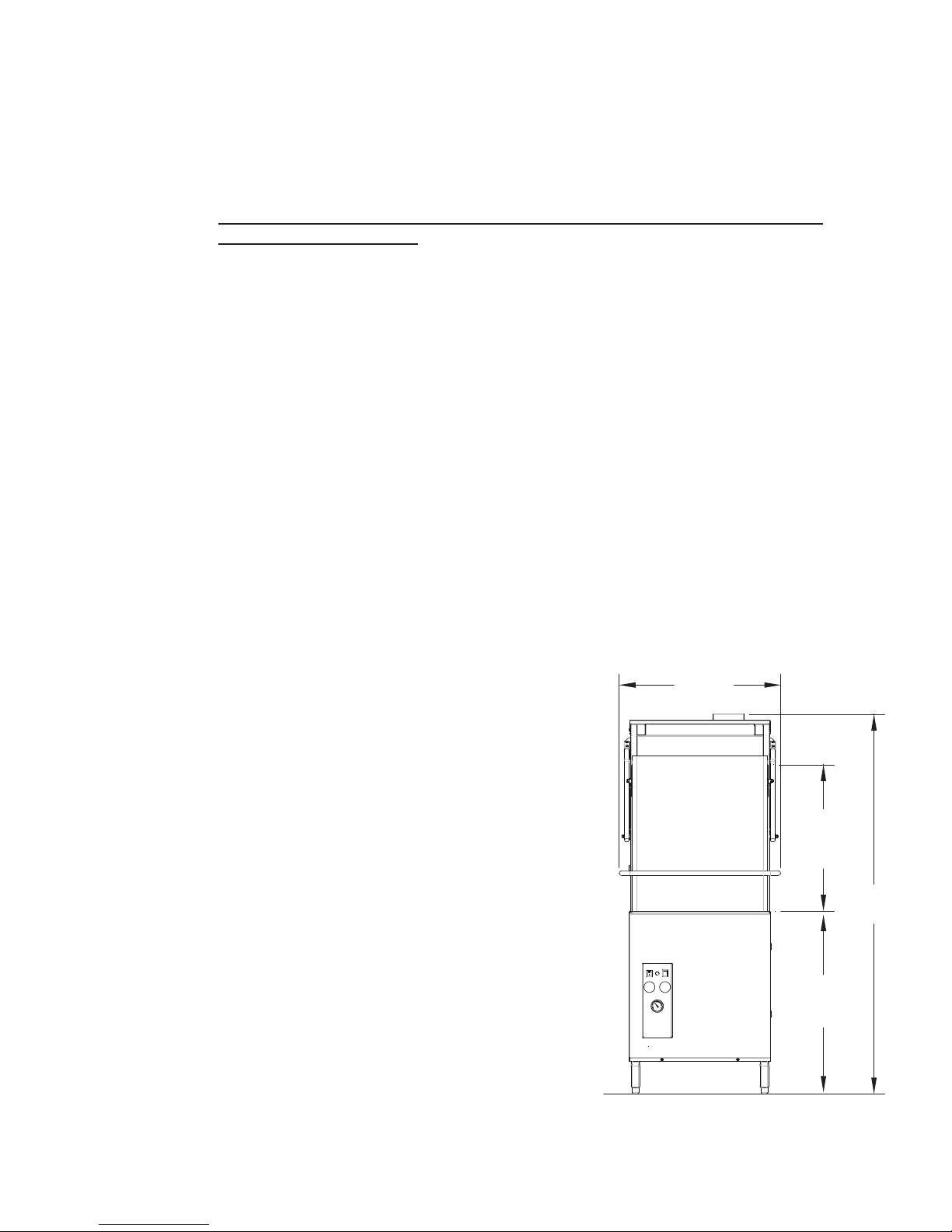
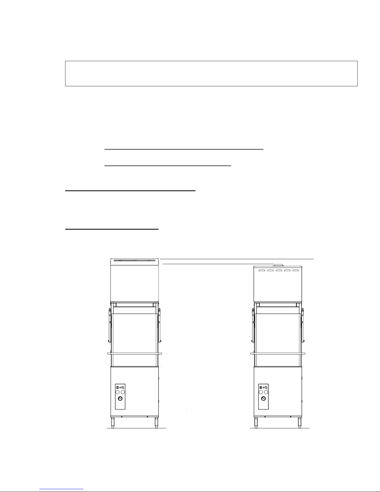
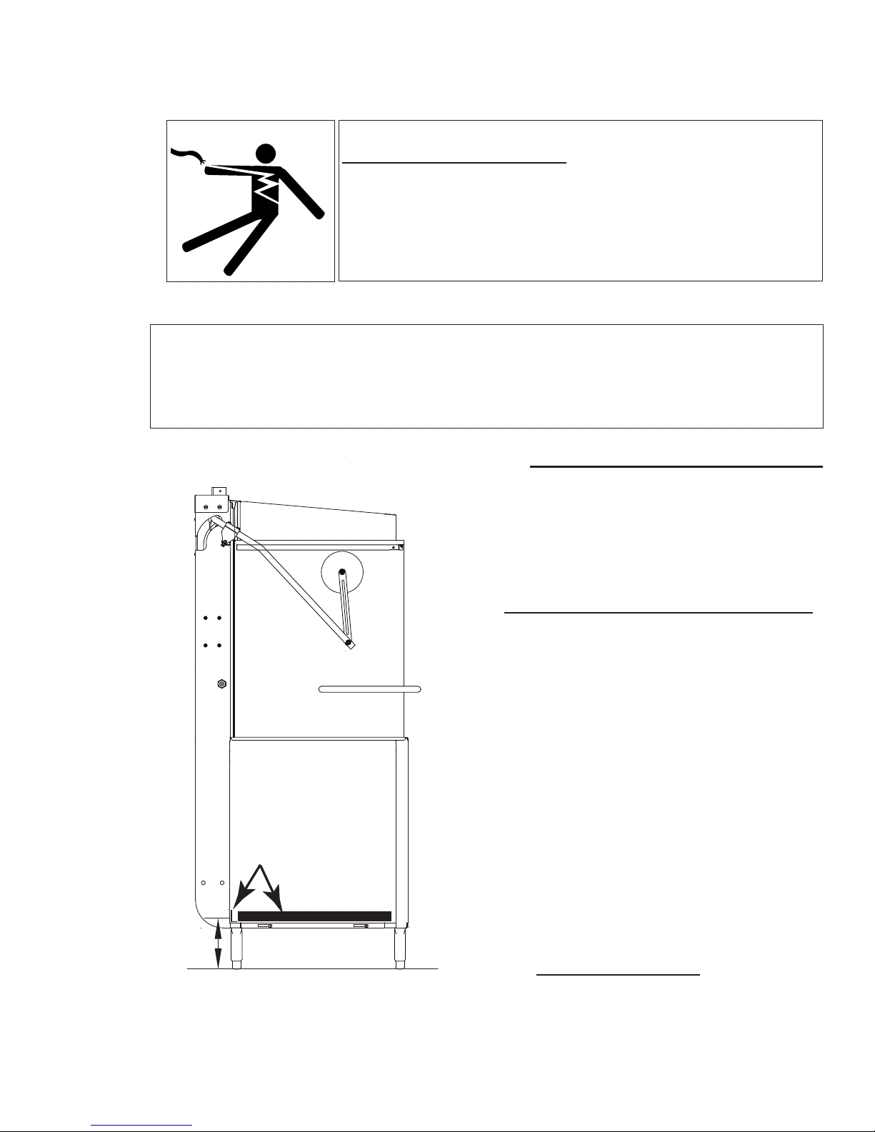
3. The typical dishwasher load height is 33¾"
[857mm].
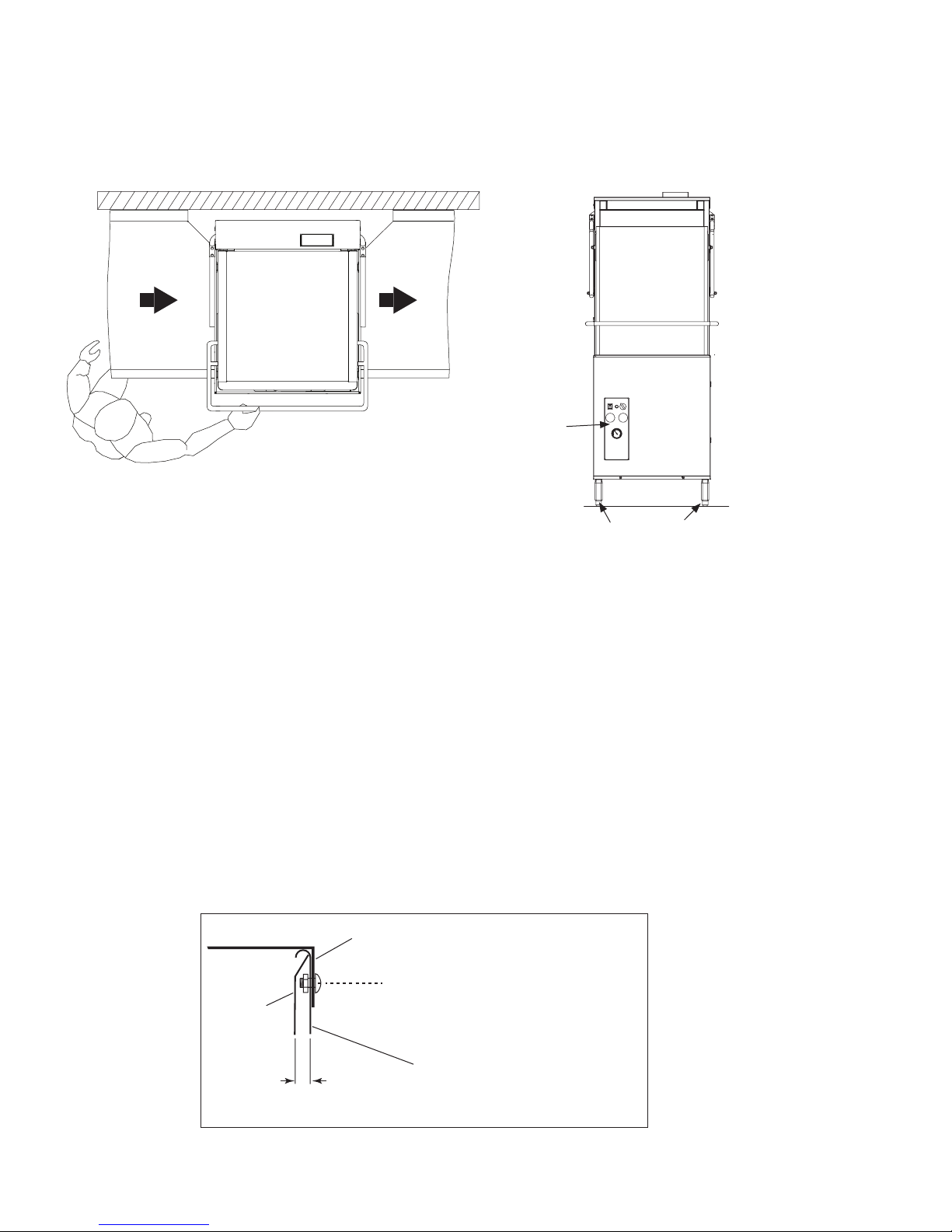
4. For straight-through operation, provide 20"
[508mm] clearance out from the front of the
machine and 20" [508mm] out from the left-side of
the machine by 27" [686mm] clearance above the
oor for servicing.
5. For servicing a corner operation machine, provide
35" [889mm] clearance out from the front of
the machine under the right-hand tabling, 35"
[889mm] out from the left-hand of the machine
under the left-hand tabling and 35" [889mm]
out from the front of the machine. Provide 27"
[686mm] clearance above the oor on all sides.
[757]
27"
[686]
Clearance
33¾"
[857]
70⅛"
[1781]
Standard DH5000T dishwasher
dimensions in inches and [millimeters].
1
Installation
Placement (continued)
6. Dishwashers are shipped from the factory for straight-through operation. Refer to
page 4 to convert the dishwasher from straight-through to corner operation.
Control
Straight-through Operation Shown
7. The dishwasher has 4 adjustable feet for leveling.
Panel
8. Level the dishwasher front-to-back and side-to-side.
Adjustable Feet
Dish Table Connections
NOTE:
Dish tables should be securely fastened to the dishwasher after the dishwasher is permanently
located and the utilities are connected.
1. Level the dishwasher and dish tables to the required height and t the dish table anges
over the ends of the dishwasher tank. Refer to the illustration below.
2. Lift the dishwasher track assembly out of the dishwasher and set aside.
3. Remove the dishwasher side panels (front and side panel for corner operation).
4. Apply a NSF approved sealant between the table anges and the wash tank.
5. Drill a minimum of two holes through the table ange and the inner wash tank.
6. Install stainless steel truss head screws or rust-proof rivets to secure the table and tank.
7. Reinstall the panels and track assembly.
Dish Table Flange
Panel
2
9/32”
Drill holes, apply NSF sealant,
& fasten flange to wash tank
Inner Wall of
Wash Tank
Installation
Installing Condensate Removal or Direct Vent Options
NOTE
Complete installation instructions are located at the end of this service manual.
The dishwasher may be equipped with either a Condensate Removal Option or a Direct Vent
Option. These options ship separately from the dishwasher in their own containers. Separate
instructions are also included attached to the front of the dishwasher. These instructions may be
requested under the document part numbers listed below:
P/N 115107, Condensate Removal Option Installation Instructions
P/N 115109, Direct Vent Option Installation Instructions
Condensate Removal System Option
The condensate removal system removes dishwasher heat and water vapor at the end of the
dishwashing cycle recovering the normally exhausted heat and transferring the recovered heat
to the built-in booster heater which may eliminate the need for a dishwasher vent hood.
Direct Vent System Option
The direct vent system option removes dishwasher heat and water vapor directly into an exhaust
vent which may eliminate the need for a dishwasher vent hood.
Condensate Removal Direct Vent
3
Installation
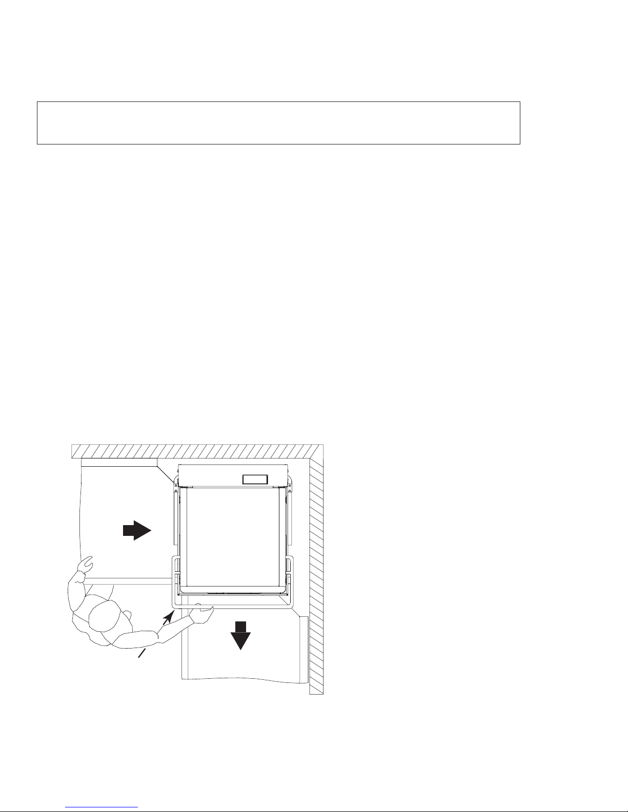
Converting Straight-through Operation to Corner Operation
! A TTENTION !
A straight-through machine can be converted to a corner configuration in the field.
Refer to the illustration below and on the next two pages to convert a straight-through operation
machine to a corner operation machine.
To convert the dishwasher:
1. Place the dishwasher as shown below so the control panel faces into the room
and is accessible to the operator.
2. Position the rear of the machine a minimum of 1-7/8" [48 mm] from the back wall and a
minimum of 5⅛" [130 mm] from the right side wall.
3. Make the utility connections as described in this manual and in accordance with all
local codes and regulations.
4. Install the dish tables so the edge of each table ts over the inner wall of the dishwasher
tank.
5. Secure the dish tables to the dishwasher
6. Seal each dish table joint with a food-grade sealant to prevent leaks.
Control
Panel
Corner Operation Shown
4
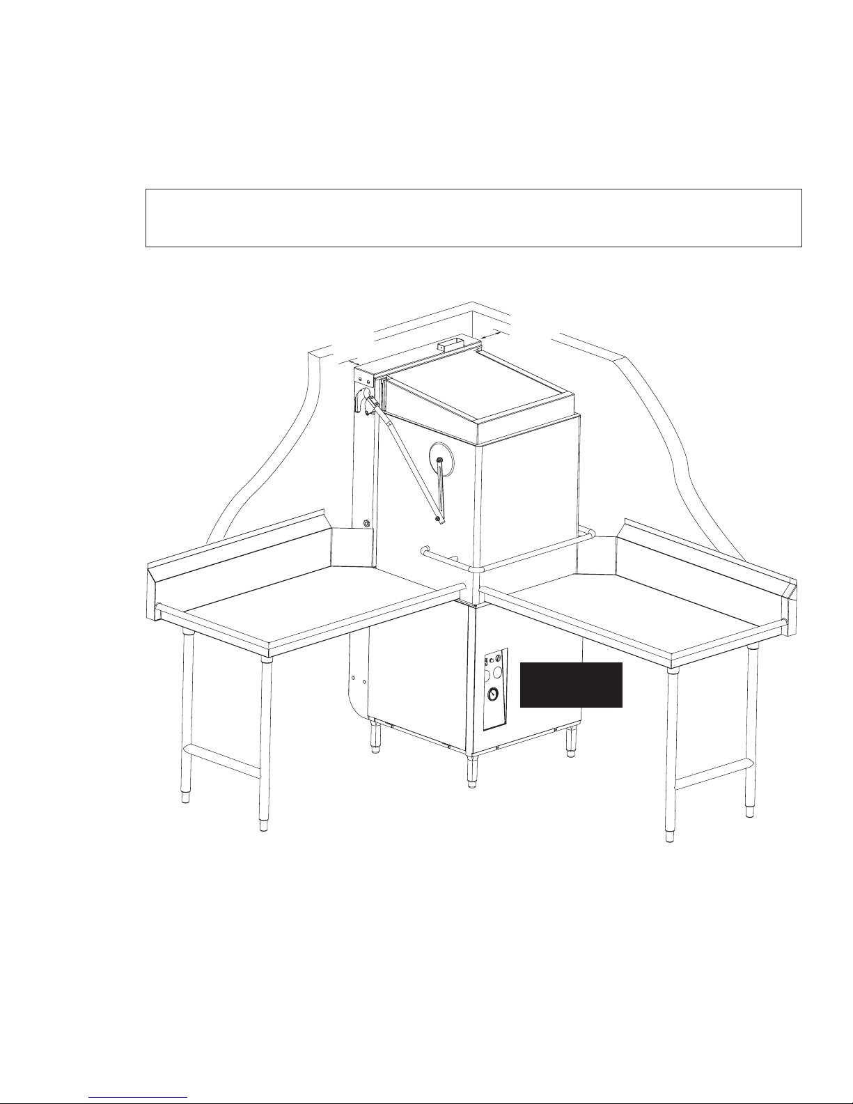
Installation
Converting Straight-through Operation to Corner Operation (continued)
! A TTENTION !
A straight-through machine can be converted to a corner configuration in the field.
1-7/8"
[48]
MIN.
5⅛"
[130]
MIN.
Controls must
be accessible.
CORNER CONFIGURATION
5
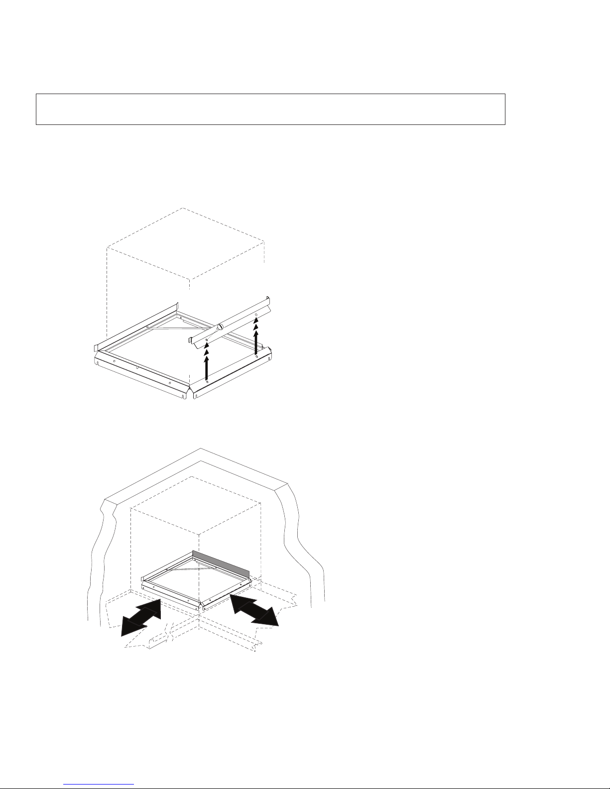
Installation
Converting Straight-through Operation to Corner Operation (continued)
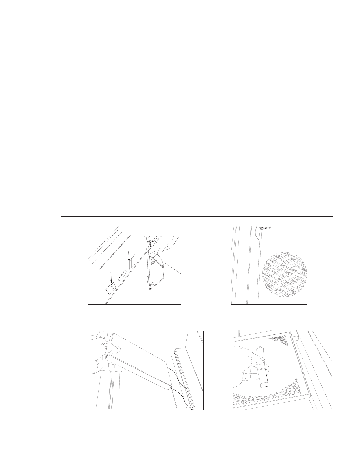
! A TTENTION !
The dish rack guides must be repositioned for corner operation.
Follow the steps below to change the dish rack guides for corner operation.
Step 1:
Remove the rack guide (A); save the fasteners.
A
Step 2:
Move (A) and re-attach as shown in the illustration below.
wall
wall
A
Step 3:
Slide a dish rack through the machine to check the dish rack clearance.
Dish racks should move smoothly without binding or tipping on the guides.
6
Installation
Electrical Connections
WARNING:
Electrocution or serious injury may result when working on an
energized circuit.
Disconnect power at the main breaker or service disconnect
switch before working on the circuit.
Lock-out and tag the breaker to indicate that work is being
performed on the circuit.
! A TTENTION !
A qualified electrician must connect the main incoming power to the dishwasher in accordance
with all local codes and regulations or in the absence of local codes in accordance with the
National Electrical Code or the Canadian Electrical Code. Improper installation will not be
covered by the Limited Warranty.
Connecting Incoming Power Supply
8¾"
[222]
Power Bracket
and Conduit
Incoming Power Routing.
1. Make sure the incoming power is disconnected
at the main disconnect switch or circuit breaker.
2. The dishwasher is available for either single or
three phase operation. Standard voltages are
208-240V/60/1 & 3, and 460-480V/60/3.
3. A Machine Electrical Connection Data Plate
is located directly below the input terminal
block. Make sure the incoming power supply
matches the machine's electrical requirement
before connecting incoming power.
4. Remove the front and left side dishwasher
panels.
5. The incoming power supply is routed from the
rear of the machine to the input terminal block
located at the front of the machine.
(See A and B on next page).
6. Connect the incoming power exible conduit to
the incoming conduit mounting bracket
located on the rear of the dishwasher base
making sure to leave 6 feet [2 m] of excess
conduit and conductors to allow for servicing of
the dishwasher.
continued on next page
7
Installation
Electrical Connections
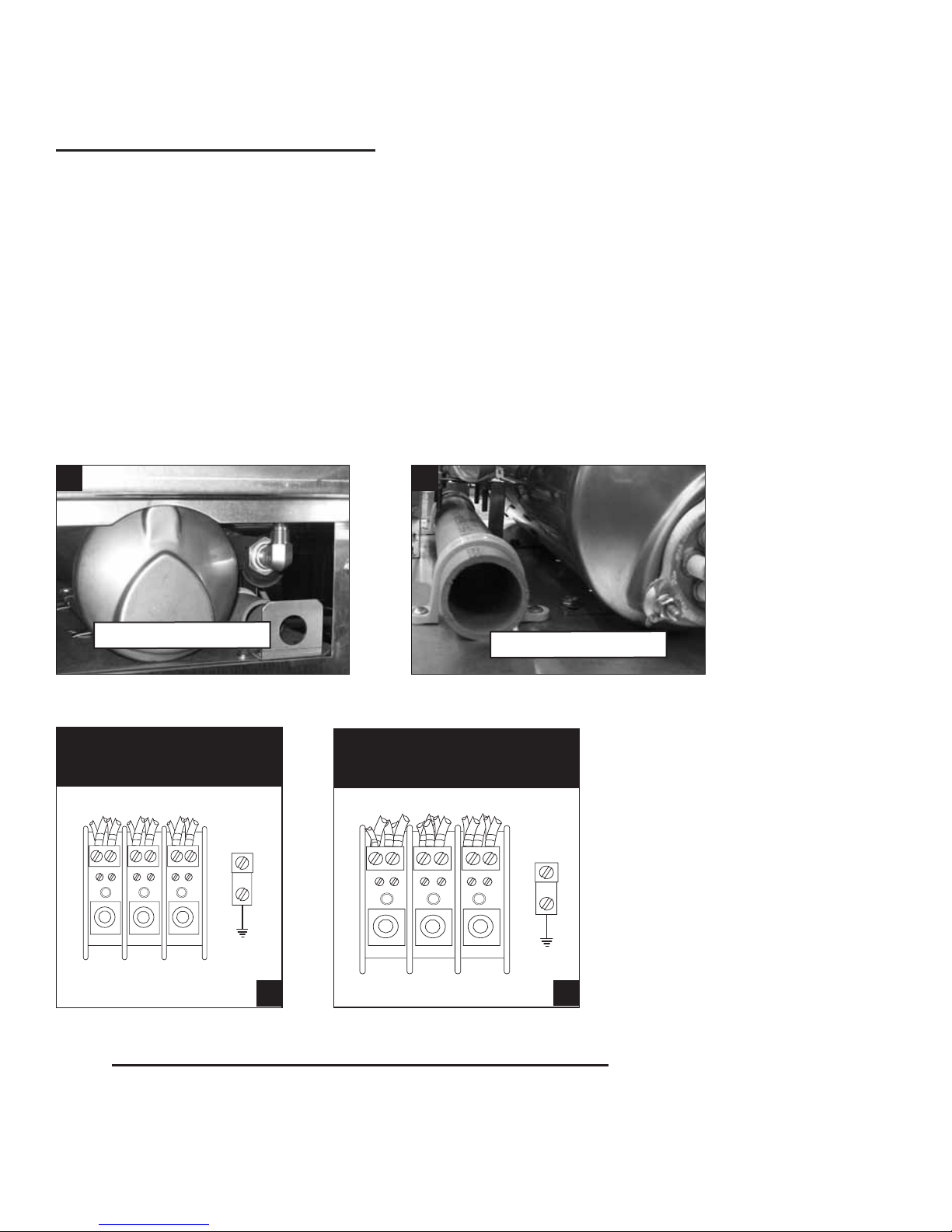
Connecting Incoming Power Supply (continued)
1. Connect the incoming power exible conduit to the incoming conduit mounting bracket
located on the rear of the dishwasher base making sure to leave 6 feet [2 m] of excess
conduit and conductors to allow for servicing of the dishwasher.
2. Route the power conductors through the 1-1/2" rigid PVC Power Cable Conduit to the
front of the dishwasher as shown. (See A and B below).
3. Two cable tie mounts are provided on the base of the machine to secure the conductors.
Make sure the conductors do not block the front of the booster tank, (if equipped), so the
booster can be serviced easily.
4. Refer to the terminal block connection diagrams below and connect the incoming
power to the input terminal block as indicated according to the machine's power
requirements. (See C and D below).
A B
Power Cable Bracket
SINGLE PHASE
POWER CONNECTION
208-240V/60/1
L1 L2 L3
GND
LINE IN
NOT
USED
L1 L2
C
THREE PHASE
POWER CONNECTION
208-240/440-480V/60/3
L1 L2 L3
L1 L2 L3
LINE IN
Power Cable Conduit
GND
D
5. CHECK MOTOR ROTATION FOR 208-240/460-480V/60/3 ONLY. Check the rotation
direction of the wash pump motor according to the indicator arrow on the motor end
cover and reverse L1 and L2 at the input terminal block if the motor rotation is incorrect.
8

Blank Page
This Page
Intentionally
Left Blank
9
Installation
Water Connections for Standard Model and Direct Vent Option Model
! A TTENTION !
A qualified plumber must connect the water supply to the dishwasher in accordance with all
local plumbing and sanitation codes and regulations.
Improper installation will not be covered by the Limited Warranty.
1. The DH5000T Standard Model dishwasher and the DH5000T Direct Vent Option Model
require a single hot water connection
HOT WATER — 3/4" NPT, 110°F/43°C minimum temperature, with a minimum incoming
owing pressure of 45 PSI measured at the dishwasher before adjusting operating
pressure to 20/25 PSI owing pressure.
2. A water hardness of 3 grains/gal (US) [51.3 mg/L] or less is recommended.
3. A manual shut-off valve, 3/4" or larger, should be installed in the hot water supply line
as close to the dishwasher as possible for servicing.
The incoming hot water line is a 3/4" NPT connection.
10
Installation
[1880]
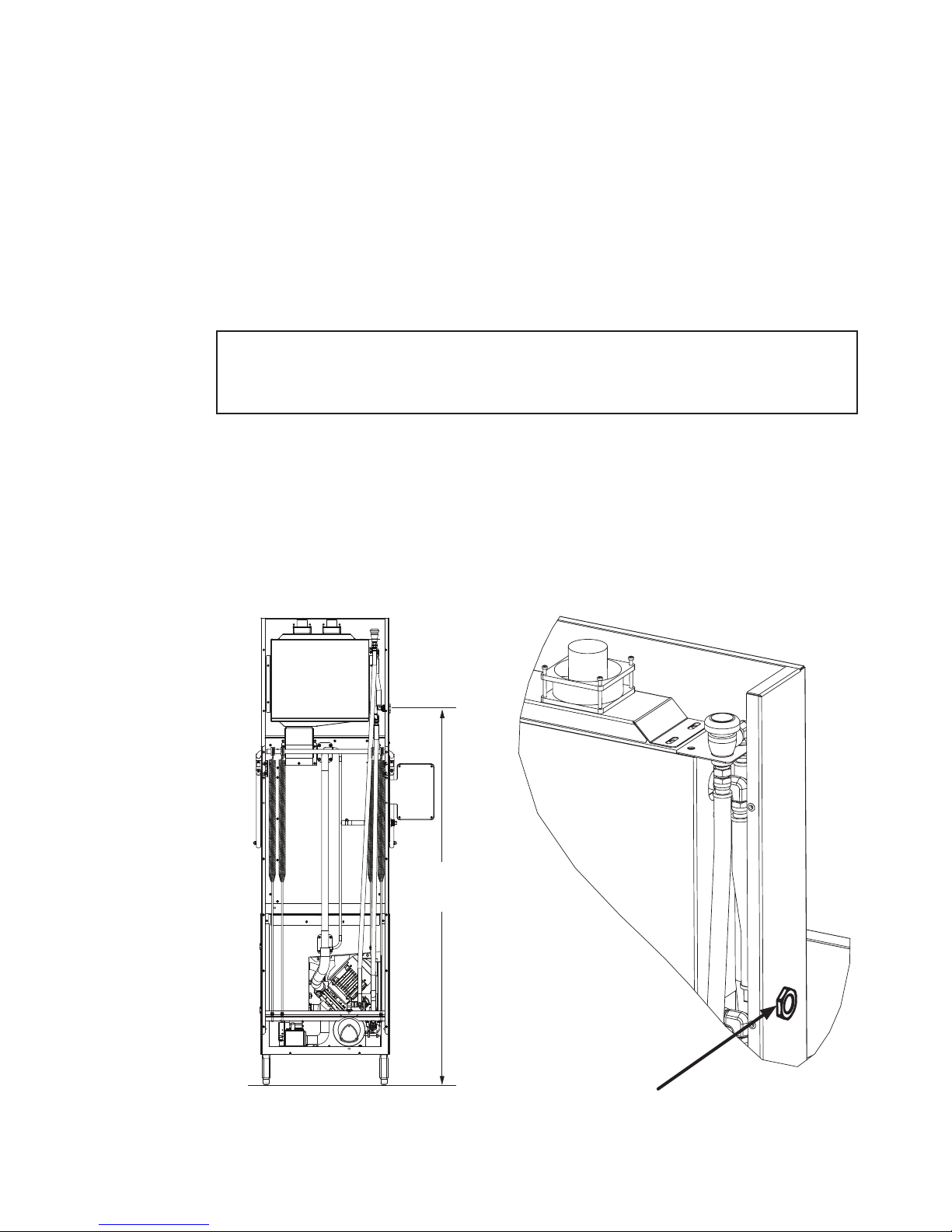
Water Connections for Condensate Removal Option Model
1. The DH5000T dishwasher equipped with a Condensate Removal Option requires an
incoming cold water supply only.
COLD WATER — 3/4" NPT, 55-75°F/13-24°C maximum temperature, with a minimum
incoming owing pressure of 45 PSI measured at the dishwasher supply connection
before adjusting operating pressure to 20/25 PSI owing pressure.
2. A water hardness of 3 grains/gal (US) [51.3 mg/L] or less is recommended.
of 45 PSI flowing pressure measured at the cold water supply connection.
3. The cold water supply connection is located on the left side of the dishwasher
approximately 74" above the nished oor (see the illustration below).
4. A manual shut-off valve, 3/4" or larger, should be installed in the cold water supply line
as close to the dishwasher as possible for servicing.
The incoming cold water supply pressure must be a minimum
! VERY IMPORTANT !
Detail View
74"
3/4" NPT
Cold water
supply connection
11
Installation
Drain Connection - All Models
The drain water connection is a 2" slip-fit hose
connection and is located at the center-rear of
the machine base. It is a gravity drain.
1. The dishwasher drain is 2" O.D. hose
connection.
2. An optional drain water tempering kit
is available (consult the factory).
3. Drain water ow is controlled by an
automatic electrically operated drain valve.
4. The oor sink and/or drain plumbing
must be able to accommodate a
maximum drain ow rate of
20 US gpm / 17 Imp gpm / 76 Lpm.
The drain is a 2" slip-fit hose connection.
Note: A Drain Water Tempering Kit Option is available to ensure the temperature of the
water entering the drain does not exceed 140ºF/60ºC (consult the factory).
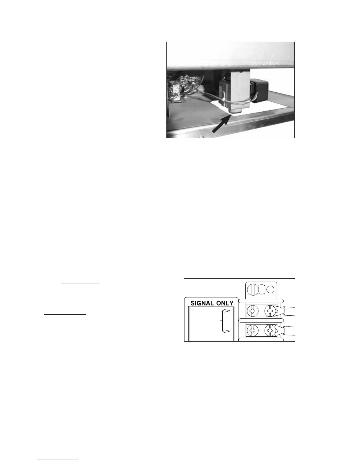
Vent Fan Control for Standard Model Only
Standard Model DH5000T installations using an overhead vent hood may require a vent fan
signal. This signal is supplied by the dishwasher control circuit.
1. A vent fan control signal is provided on a terminal
block located inside the control cabinet.
The terminal locations are clearly marked.
2. The 120VAC signal is designed only to operate an
external vent fan contactor (supplied by others) and
is limited to .5 AMP maximum load and is available
when the dishwasher power switch is turned ON.
CAUTION:
Do not connect a vent fan motor to the signal
connection terminals.
VENT FAN
120V .5A
The Vent Fan Control Signal is limited to
120VAC .5 Amp maximum load.
12

Installation
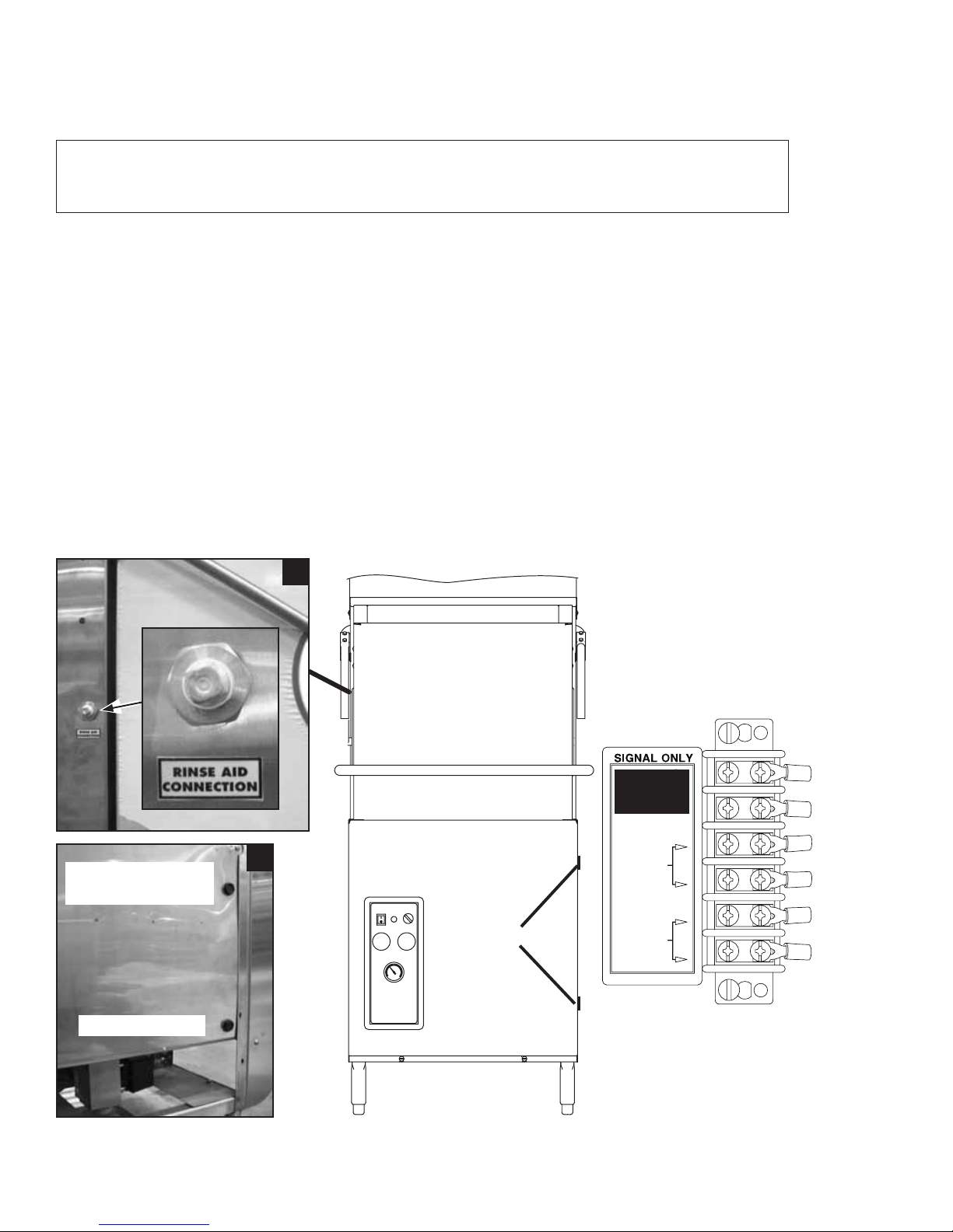
Standard Model and Direct Vent Option Model Chemical Dispensing Provisions
! A TTENTION !
Consult a qualified chemical supplier for chemical supplies and chemical dispensing
equipment.
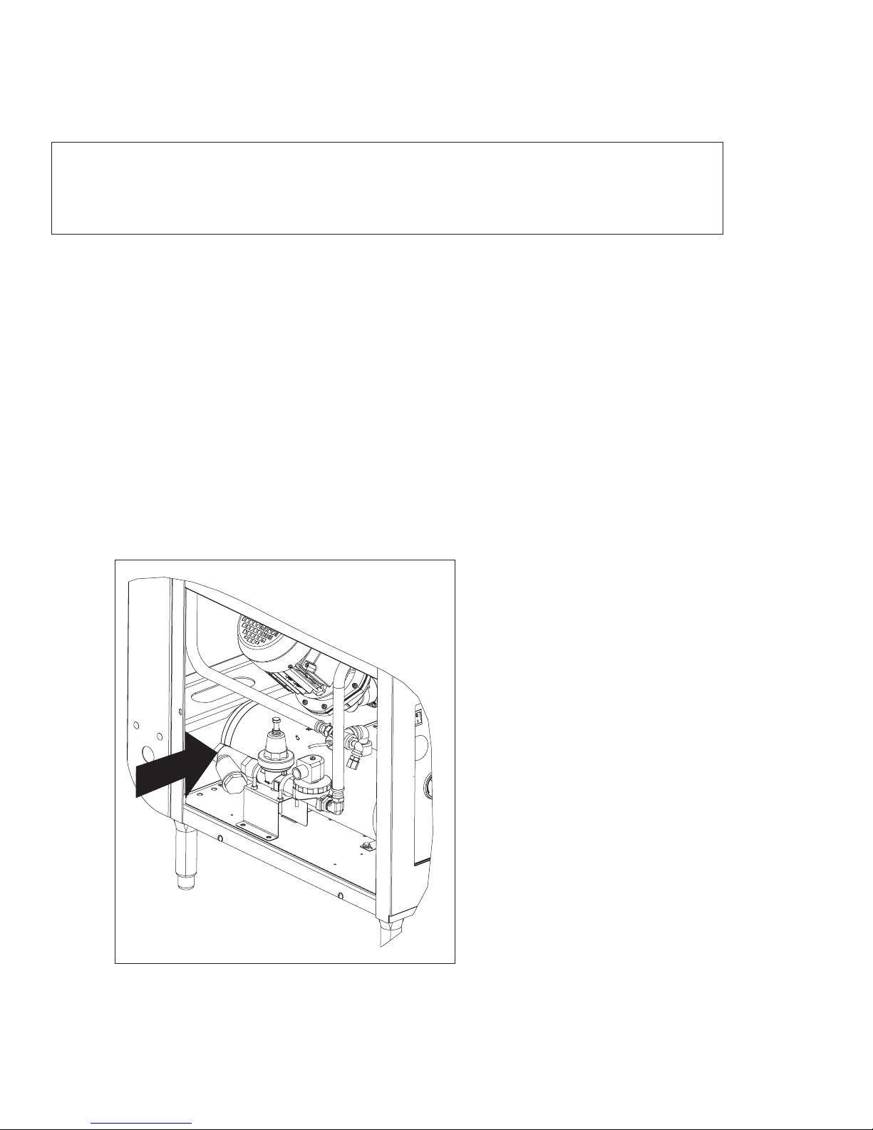
Provisions for chemical suppliers to connect their chemical dispensing systems are provided on
the dishwasher and include:
1. A 1/8" NPT tting (A) rinse-aid injection point. The tting is located on the left side
of the dishwasher support hood (see illustration below).
2. Two 7/8" holes (B) are provided on the lower right side of the wash tank for detergent
injection and the detergent probe.
3. Detergent and rinse-aid control signals are available inside the control cabinet.
4. The signals are 120VAC, Max. 1 Amp load. Connection points are located on a
labeled terminal block (see below).
Detergent Injection
Point
Detergent Probe
A
A
VENT FAN
120V .5A
B
B
RINSE AID
120V 1A
DETERGENT
120V 1A
120VAC, 1A Dispenser
Signal Terminal Block
13
Installation
Chemical Dispensing Provisions - Condensate Removal Option Model Only
! A TTENTION !
Consult a qualified chemical supplier for chemical supplies and chemical dispensing
equipment.
Provisions for chemical suppliers to connect their chemical dispensing systems are provided on
the dishwasher and include:
1. A 1/8" NPT tting (A) rinse-aid injection point. The tting is located on the left side
of the dishwasher support hood (see illustration below).
2. Two 7/8" holes (B) are provided on the lower right side of the wash tank for detergent
injection and the detergent probe.
3. Detergent and rinse-aid control signals are available inside the control cabinet.
4. The signals are 120VAC, Max. 1 Amp load. Connection points are located inside the
control cabinet on a labeled terminal block (see below).
Detergent Injection
Point
Detergent Probe
B
A
B
VENT FAN
120V .5A
RINSE AID
120V 1A
DETERGENT
120V 1A
120VAC, 1A Dispenser
Signal Terminal Block
14
Initial Start-up
Initial Start-up Check List
1. Remove any protective lm from dishwasher. Check the interior for foreign material.
2. Make sure the dishwasher is permanently located.
3. Make sure all utility connections are complete.
4. Make sure the chemical supply containers are full.
5. Make sure the pump suction screen is in place.
6. Make sure the drain screen is clean and unobstructed by debris.
7. Make sure the scrap screen plate and scrap screens installed and rmly seated.
The screen plate is mounted in the center of the wash tank and locks in a slot on the
back screen support.
8. Make sure the spray arms are in place and spin freely.
9. Close the dishwasher hood.
10. Turn hot water supply on and check for leaks in the main water supply piping connected
to the dishwasher.
IMPORTANT
During the initial fill, adjust the PRV to ensure the flowing pressure of the incoming water
is set between 20-22 PSI.
Make sure the pump suction strainer is in place.
Make sure the drain screen is clean.
Make sure the scrap screen plate is mounted in the center
of the wash tank and separating the scrap screens.
Make sure the scrap screens are in place.
15
Operation
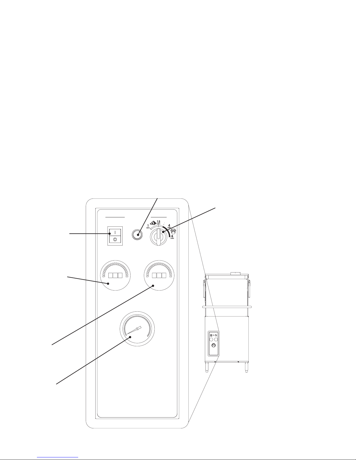
Control Panel Description
The control panel is located on the front left side of the lower panel. The controls include:
A - ON/OFF DRAIN power switch. Turns power on and off and initiates a drain cycle
when the switch is placed in the Off/Drain position.
B - CYCLE green indicator light. Illuminates during an automatic timed cycle.
The cycle light is off during the 10 minute automatic drain cycle.
C- CYCLE SELECTOR switch. 4 positions provide 1 minute, and 1.5 minute total cycle times for normally
soiled wares and 4 minute and 6 minute total cycle times for pots, pans and heavy soiled wares.
D- WASH (150°F) digital temperature display. Indicates the wash tank water temperature
whenever the dishwasher tank is full of water (See next page, Digital Temperature Displays).
E- RINSE (180°F) digital temperature display. Indicates the final rinse water temperature
during the final rinse (See next page, Digital Temperature Displays).
F- PRESSURE gauge. Indicates the final rinse water flowing pressure during the final rinse.
The proper pressure reading is 20-22 PSI during the final rinse.
B
C
POWER WASH
ON
A
CYCLE
OFF/DRAIN
D
WASH
150°F
RINSE
180°F
E
PRESSURE
F
16
Operation
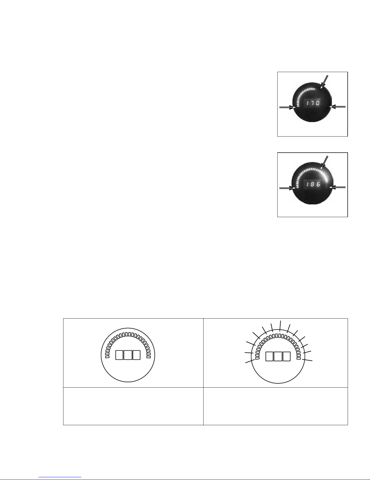
Digital Temperature Display Description
The wash tank and the final rinse temperatures are numerically displayed and a colored bar
around the numbers creates a visual indication of the temperature.
1. When the color of the bar is yellow then the water temperature
is below the minimum temperature required to operate the
machine. Wait until the temperature has reached the proper
operating temperature.
2. When the color of the bar is yellow and green then the water
temperature is at or above the minimum temperature required
to operate the machine.
3. The required wash temperature is a minimum of 150ºF/66ºC.
Wait until the display indicates this temperature before
washing dishes.
4. The required final rinse temperature is a min/max of
180-195ºF/82-91ºC. Contact a factory authorized service
agent if the display fails to indicate this temperature
during the final rinse.
W
O
L
L
E
Y
W
O
L
L
E
Y
G
G
R
E
E
N
R
E
E
N
NOTE:
The final rinse display may indicate a temperature that is less than a minimum of 180ºF/82ºC
during the wash cycle. This is normal, but during the final rinse (when the pressure gauge
indicates a flowing pressure of 20-22 PSI), the final rinse temperature display will read between
180-195ºF/82-91ºC.
Temperature Display Error Codes
A digital display may show an error code to indicate certain conditions that require service or
repair. Refer to the illustrations below for the meaning of the error codes.
E
The letter "E" is displayed with a dark
color bar indicates a problem exists in the
electrical circuit. Contact an authorized
service agent to correct the problem.
Three "H"s displayed with the color bar fully
lit indicates the temperature has exceeded
210ºF/99ºC. Contact an authorized service
agent to correct the problem.
HHH
17
Operation
Standard Wash Cycle Operation
Follow the instructions below to operate the dishwasher in a Standard Wash Cycle. A Rinse
Sentry feature holds the dishwasher in a wash cycle if the booster heater temperature is below
180ºF/82ºC.
1. Turn the main power on at the main circuit breaker.
2. Make sure the spray arms and the scrap screens are in place.
3. Turn the water supply on.
4. Close the dishwasher hood.
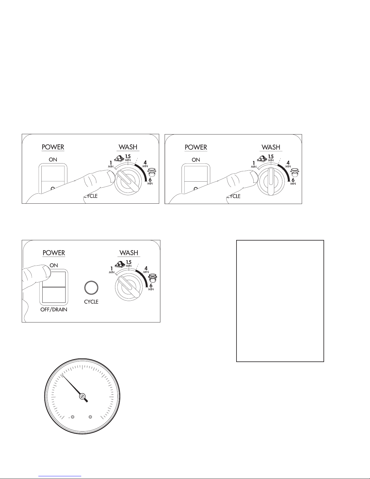
5. Turn the wash cycle selector switch to the desired standard setting of 1 or 1.5 minutes.
I
Standard 1 minute Setting
I
Standard 1.5 minute Setting
6. Push the dishwasher Power Switch to the ON position. The power switch will illuminate
and the machine will ll with water.
! VERY IMPORTANT !
THE STANDARD CYCLE
MAY BE SELECTED
I
BEFORE OR AFTER
THE POWER SWITCH
O
IS PRESSED; BUT, THE
CYCLE SELECTOR
SWITCH WILL NOT
CHANGE THE CYCLE
FROM 1 MINUTE TO 1.5
7. Check the pressure gauge as the machine lls and make
sure the incoming water owing pressure is between 20-22 psi.
MINUTES OR VICE VERSA
WHILE THE DISHWASHER
IS ALREADY IN CYCLE.
30
20
PSI
10
0
40
50
60
18
Operation
I
01
01
Standard Wash Cycle Operation (continued)
8. Wait up to 10 minutes for the WASH temperature display to indicate a minimum of
150ºF/66ºC.
NOTE:
The final rinse display may indicate a temperature
that is less than a minimum of 180ºF/82ºC during
the wash cycle. This is normal, but during the
final rinse (when the pressure gauge indicates a
flowing pressure of 20-22 PSI), the final rinse
temperature display will read between
180-195ºF/82-91ºC.
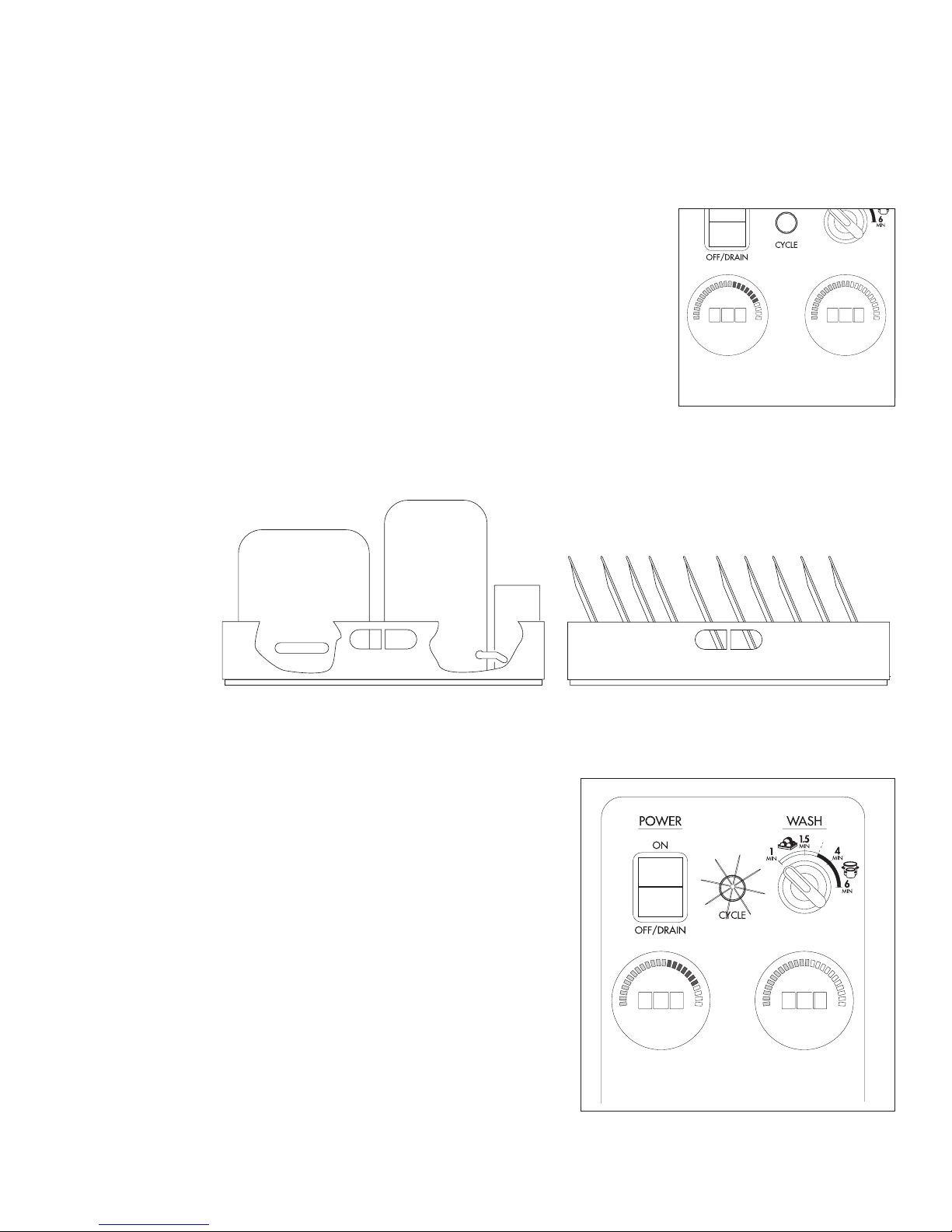
9. Load soiled wares into the dish rack. Place plates, glasses, cups and bowls in a peg
rack. Place utensils in a single layer in a flat-bottom rack. Place pots and pans in a flatbottom rack. Do not overload the dish racks.
O
15
WASH
150°F
70
RINSE
180°F
10. Slide 1 dish rack into the wash compartment making sure the wares do not interfere with
11. Close the hood, the green CYCLE light
the rotating spray arms. Do not wash more than 1 dish rack at a time.
will illuminate and the standard wash
cycle will begin automatically.
(continued on next page)
I
O
15
WASH
150°F
70
RINSE
180°F
19

Operation
Standard Wash Cycle Operation(continued)
12. The wash cycle time runs for the selected time.
13. Opening the hood when the dishwasher is in-cycle will pause the cycle. The cycle will
resume automatically when the dishwasher hood is closed.
14. The nal rinse cycle begins at the end of the wash cycle and runs for approximately
10 seconds followed by a 15 second delay before the green CYCLE light goes out.
15. Check the FINAL RINSE temperature gauge during the nal rinse and make sure it indicates
a minimum of 180ºF/82ºC. The acceptable range of operation is 180-195ºF/82-91ºC.
180
RINSE
180°F
16. Check the pressure gauge located below the temperature displays to ensure the final rinse
pressure maintains a flowing pressure between 20-22 PSI.
30
20
10
0
17. At the end of the rinse cycle, the in-cycle light will go out. Open the hood and remove
the clean rack of wares.
18. Repeat steps 9-17 for additional dish racks.
19. Refer to the Automatic Drain Cycle on the next page for the procedures to drain the dishwasher.
40
PSI
50
60
20
Operation
Automatic Drain Cycle
The dishwasher can be drained automatically when the dishwasher has completed a normal
wash cycle or whenever the dishwasher is idle.
To drain the dishwasher:
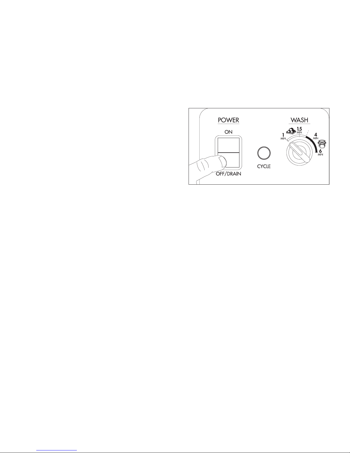
1. Push the dishwasher power Switch down to the OFF/DRAIN position. The illuminated
power switch will go out. The automatic drain valve will open and the machine will drain.
2. The CYCLE light is not illuminated
during the automatic drain cycle.
I
O
3. The drain valve will remain open for 10 minutes to allow time to ush the interior with fresh
water during a cleaning operation.
4. When 10 minutes has elapsed, the drain valve will close.
The automatic drain cycle is complete.
NOTE:
The automatic drain cycle can be repeated after 10 minutes by pushing the power Switch to ON
and immediately to OFF/DRAIN. The dishwasher will drain for another 10 minutes and then
turn off.
21
Operation
Heavy Duty Wash Cycle Operation
! VERY IMPORTANT !
THE HEAVY DUTY CYCLE MAY BE SELECTED BEFORE OR AFTER THE POWER SWITCH IS
PRESSED; BUT, THE CYCLE SELECTOR SWITCH WILL NOT CHANGE THE CYCLE FROM 4
MINUTES TO 6 MINUTES OR VICE VERSA WHILE THE DISHWASHER IS ALREADY IN CYCLE.
Follow the instructions below to operate the dishwasher in the Heavy Duty Wash Cycle. A Rinse
Sentry feature holds the dishwasher in a wash cycle if the booster heater temperature is below
180ºF/82ºC.
1. Turn the main power on at the main circuit breaker.
2. Make sure the spray arms and the scrap screens are in place.
3. Turn the water supply on.
4. Close the dishwasher hood.
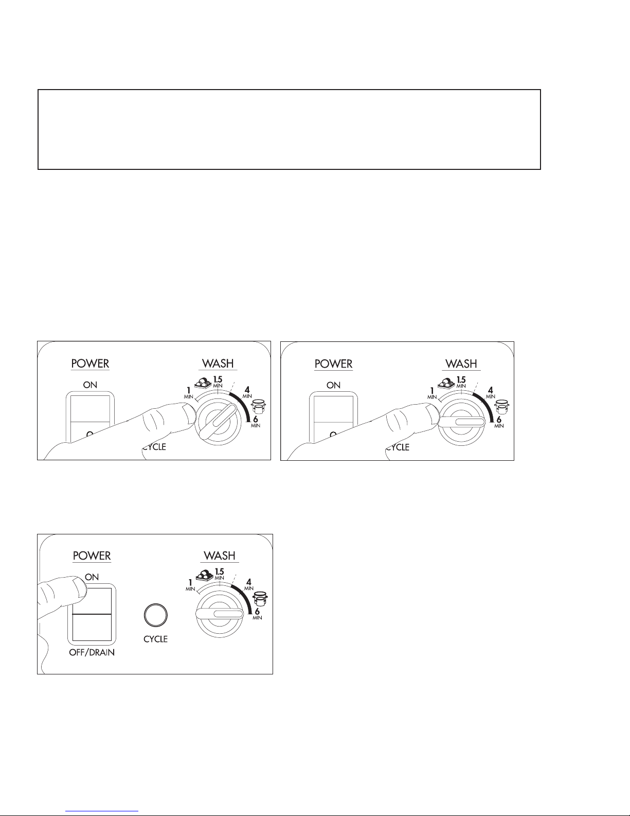
5. Turn the wash cycle selector switch to the desired heavy duty setting of 4 or 6 minutes.
I
Heavy Duty 4 minute Setting
I
Heavy Duty 6 minute Setting
6. Push the dishwasher Power Switch to the ON position. The power switch will illuminate
and the machine will ll with water.
I
O
22
 Loading...