

Page 1
FLIGHTMASTER JR.®
TRAP OWNER’S INSTRUCTION MANUAL
WARNING: THIS MACHINE CAN CAUSE SERIOUS INJURY OR DEATH !
THOROUGHLY READ INSTRUCTIONS AND SAFETY INFORMATION
BEFORE ASSEMBLING, INSTALLING OR OPERATING TRAP !
KEEP THIS INSTRUCTION MANUAL FOR FUTURE REFERENCE.
PART NO. 40240
Page 2

ENGLISH
FRANÇAIS
2-7
813
Page 3
2
WARNING: IMPACT FROM THE POWERFUL SPRING-LOADED THROWING ARM OR FLYING OBJECTS CAN
CAUSE SEVERE PERSONAL INJURY OR DEATH. ALL PERSONS IN THE AREA OF THE TRAP OPERATION MUST KEEP
CLEAR OF THROWING ARM AND THE PATH OF THE TARGETS TO AVOID INJURY.
• OPERATE TRAP FROM REAR ONLY. DO NOT LEAVE TRAP UNATTENDED WHEN COCKED.
• READ MANUAL CAREFULLY AND THOROUGHLY BEFORE ASSEMBLING AND OPERATING THE TRAP.
• MAKE SURE ALL OPERATORS READ AND UNDERSTAND THIS INSTRUCTION MANUAL.
• ALL PERSONS IN THE AREA OF THE TRAP OPERATION MUST WEAR EYE AND HEARING PROTECTION.
• THIS TRAP IS CAPABLE OF THROWING TARGETS A DISTANCE OF OVER 70 YARDS. USE ONLY IN AREAS WHERE
THERE IS NO RISK OF CAUSING INJURY TO ANOTHER PERSON OR CAUSING OTHER DAMAGE.
Congratulations on the purchase of your CHAMPION Trap!
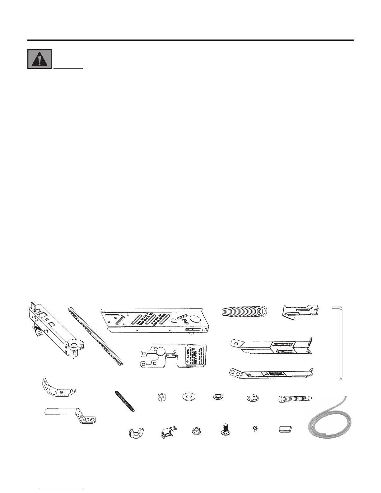
Unpack components from the box and identify all parts before proceeding.
SAFETY INSTRUCTIONS
TRAP PARTS LIST:
A. Trap Body - 1 Ea.
B. Flight Rail (Rubber Strip) - 1 Ea. (pre-assembled)
C. Throwing Arm - 1 Ea.
D. Arm Support - 1 Ea.
E. Main Spring - 1 Ea.
F. Rear Leg - 1 Ea.
G. Right Front Leg - 1 Ea.
H. Left Front Leg - 1 Ea.
I. Support Bracket - 1 Ea.
J. Wrench w/Vinyl Grip - 1 Ea. (pre-assembled)
K. Release Cord - 1 Ea.
M. Metal Stakes - 3 Ea.
HARDWARE (PACKED IN PLASTIC BAGS):
L-1 Small Spring (For Ratchet) - 1 Ea.
L-2 Hex Nut, 10mm - 1 Ea.
L-3 Flat Washer, 10mm - 1 Ea.
L-4 Nylon Washer - 1 Ea.
L-5 E-Clip - 1 Ea.
L-6 Hex Bolt, 10mm x 70mm - 1 Ea.
L-8 Wing Nut, 10mm - 1 Ea.
L-9 Black Plastic Target Clip - 1 Ea.
L-10 Flange Nuts, 8mm - 8 Ea.
L-11 Carriage Bolts, 8mm x 20mm - 8 Ea.
L-12 Screws, 4mm x 8mm - 3 Ea. (pre-assembled)
L-13 Red Vinyl Grip (Trigger) - 1 Ea. (pre-assembled)
A
B
C
D
I
J
K
L-8 L-9 L-10 L-11 L-12 L-13
L-6L-5L-4L-3L-2L-1
H
G
FE
K
M
Page 4
3
ASSEMBLY INSTRUCTIONS
FIG. 7
C
B
L-12
A
FIG. 4
L-10
F
L-11
FIG. 5
H
L-10
L-11
G
FIG. 6
L-11
L-10
L-11
L-10
ATTACH NUT
FROM THIS SIDE
FINGER TIGHTEN ONLY
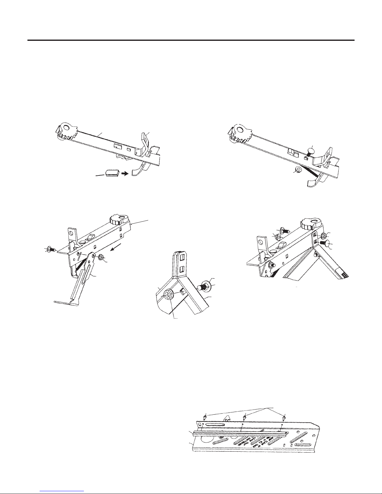
ADDITIONAL TOOLS REQUIRED: One Standard Slotted (Flat Blade) Screwdriver.
STEP 1: (FIG. 2) Slide Red Vinyl Grip (L-13) onto Trigger. Insert Support Bracket (I) into Trap Body (A).
(FIG. 3) Install one Carriage Bolt (L-11) and one Flange Nut (L-10). Tighten securely with Wrench.
STEP 2: (FIG. 4) Attach Rear Leg (F) to Trap Body (A) using one Carriage Bolt (L-11) and one Flange Nut (L-10).
NOTE: Nut must be attached on right side as indicated in FIG. 4. Tighten securely with Wrench.
STEP 3: (FIGS. 5 & 6) Join Right and Left Front Legs (G & H) together with Carriage Bolt and Flange Nut.
Finger tighten only. Attach Legs to Trap Body (A) using 2 Carriage Bolts (L-11) and 2 Flange Nuts (L-10).
NOTE: Bolts and Nuts must be attached in exact position as FIG. 6 to allow use of Wrench. Securely tighten all
three nuts with wrench.
STEP 4: (Pre-Assembled) (FIG. 7) Attach Flight Rail (B) to Throwing Arm (C) using three (3) 4mm x 8mm
Screws (L-12). Tighten securely with a Standard (slotted) Screwdriver. NOTE: It is normal for these screws to
be somewhat dicult to turn.
FIG. 2
TRIGGER
L-13
I
A
FIG. 3
L-11
L-10
TRIGGER SPRING
NOT SHOWN
TRIGGER
Page 5
4
ASSEMBLY INSTRUCTIONS (CONTINUED)
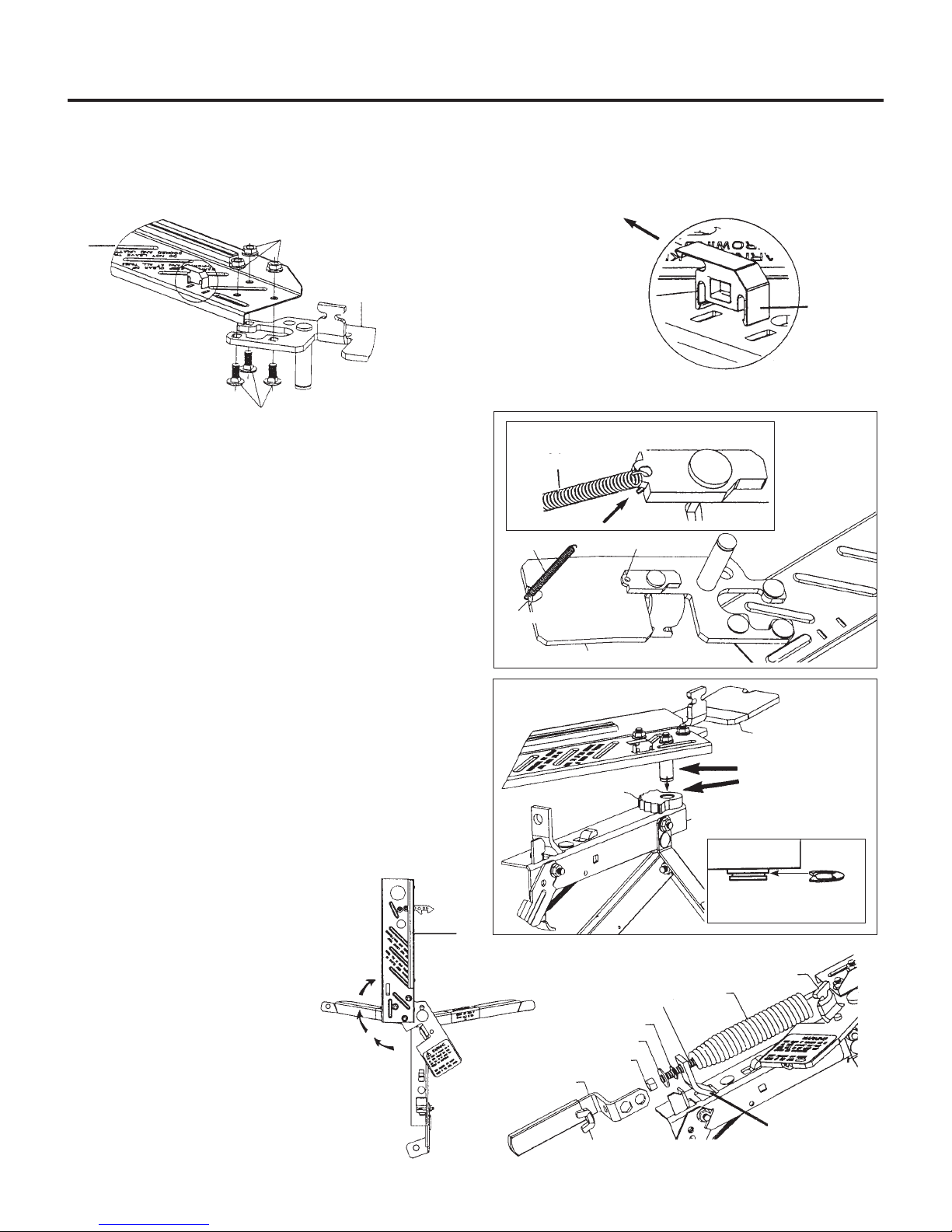
STEP 5: (FIG. 8) Attach Throwing Arm (C) to Arm Support (D) using 3 Carriage Bolts (L-11) and 3 Flange Nuts (L-10).
Bolts should attach from underside, and Flange Nuts from top onto Throwing Arm. Tighten securely with Wrench.
STEP 6: (FIG. 9) Attach Target Clip (L-9) to Throwing Arm (C) by pressing it into the two slots making sure it “snaps” into
place. Be sure “nger” of Target Clip points in direction shown.
STEP 7: (FIG. 10) Attach Small Spring (L-1) to Arm
Support (D). First, hook one end of Spring into Groove,
and then hook the other end through hole in Pawl.
IMPORTANT: MAKE SURE END OF SPRING IS
HOOKED COMPLETELY THROUGH HOLE IN PAWL.
STEP 8: (FIG. 11) Apply Lubricant and then insert
Shaft of Arm Support (D) into Trap, as shown. Make
sure there is no gap between the Arm Support and the
Gear. If there is a gap, rotate the Arm Support until it
drops in place. Press the E-Clip (L-5) into Shaft Groove.
This will take a reasonable amount of force, so use Pliers to
press the E-Clip into place.
STEP 9: (FIG. 12) Swing Arm clockwise to the
12 o’clock position. Do not swing arm past the 12
o’clock position. Throwing Arm (C) should be in line
with Trap Body.
STEP 10: (FIG. 13) Drop Hex Bolt (L-6) inside Main
Spring (E). Connect loop of Main Spring to Arm Support (D)
and place bolt through hole in Support Bracket (I). Attach
Nylon Washer (L-4),
Flat Washer (L-3), and Hex
Nut (L-2). Tighten Nut
until Spring is taut. Gap
between end of Mainspring
and Bracket should not be
more than 1 inch. Attach
Wrench (J) and hold in
place with Wing Nut (L-8).
FIG. 9
L-9
FIG. 8
L-10
D
C
L-11
FINGER POINTS TOWARDS
TIP OF THROWING ARM
FIG. 10
HOOK SPRING COMPLETELY
THROUGH PAWL HOLE
L-1
L-1
D
FIG. 11
D
A
FIG. 13
D
E
J
L-6
L-4
L-3
L-2
L-8
GROOVE
PAWL
APPLY
LUBRICANT
TO SHAFT AND
TOP OF GEAR
GEAR
E-CLIP
(L-5)
I
HOOK SPRING COMPLETELY
THROUGH PAWL HOLE
FIG. 12
C
Page 6

5
WARNING: IMPACT FROM THE POWERFUL SPRING-LOADED THROWING ARM OR FLYING OBJECTS CAN CAUSE
SEVERE PERSONAL INJURY OR DEATH. ALL PERSONS IN THE AREA OF TRAP OPERATION MUST KEEP CLEAR OF THROWING
ARM AND THE PATH OF THE TARGETS TO AVOID INJURY. DO NOT STAND IN FRONT OF TRAP AT ANY TIME. OPERATE TRAP
FROM REAR ONLY. STAY CLEAR OF THROWING ARM AT ALL TIMES. DO NOT LEAVE TRAP COCKED AND UNATTENDED.
• OPERATE TRAP ONLY WITH TRIGGER SPRING IN PLACE AND IN GOOD CONDITION. CHECK TRIGGER SPRING PRIOR TO
EACH USE OF TRAP. REPLACE IF BENT, RUSTED, OR BROKEN.
• ALL PERSONS IN THE AREA OF THE TRAP OPERATION MUST WEAR EYE AND HEARING PROTECTION.
STEP A - SETTING UP TRAP: PLACE THE TRAP ON A CLEAR AREA OF GROUND. Insert Metal Stakes through holes in feet
to support Thrower.
STEP B - COCKING TRAP: (FIG. 14) Grasp Throwing Arm with right hand and grasp Wrench with left hand. Pull Throwing
Arm Clockwise into the Latched position. MAKE SURE THE LATCH IS FULLY ENGAGED BEFORE RELEASING GRIP ON
THE THROWING ARM.
STEP C - LOADING TARGETS: PLACE CLAY TARGET ON THROWING ARM.
(Fig. 15) Place Target at on the Throwing Arm with the edge of the Target tucked underneath the Rubber Strip of the
Flight Rail and also underneath the nger of the Target Clip.
STEP D - THROWING TARGETS: (Fig. 15)
CAUTION: TRAP WILL MOVE VERY SUDDENLY WHEN THE TARGET IS RELEASED.
Method 1: Place left hand on the Wrench and right hand on the Rear Leg of Trap. Firmly grasp Wrench and press down
on Wrench with palm of left hand. Pull Trigger with the right forenger to release target.
Method 2: Once Trap is cocked, pull Release Cord (K) to trigger Trap. The
Trap will store the remaining energy of motion and the Throwing Arm will
automatically return to a partially cocked position (2 to 4 o’clock position).
(FIG. 16). To throw additional targets, repeat STEPS B through D.
STEP E - THROWING DISTANCE ADJUSTMENT: To adjust Mainspring,
remove Wrench and tighten (clockwise direction) or loosen (counterclockwise) 10mm Hex Nut (L-2) on Hex Bolt (L-6). Experiment to nd desired
throwing distance by turning just one full turn at a time.
NOTE: When loosening the Spring, do not allow a gap of more than 1”
between the Support Bracket and the end of Spring. (FIG. 16).
OPERATING INSTRUCTIONS
FIG. 14
FIG. 15
COCKING THE TRAP
REQUIRES APPROXIMATELY
40 POUNDS OF FORCE.
KEEP PRESSURE DOWNWARD ON
HANDLE WHEN PULLING TRIGGER
FIG. 16
2 TO 4 O’CLOCK
POSITION
1” MAXIMUM GAP
Page 7

TROUBLESHOOTING
SYMPTOM: Targets break when thrown.
CORRECTIVE ACTION:
• Make sure Target is touching Flight Rail when Target is placed on Throwing Arm.
• Check entire Trap for loose Nuts and Screws. Tighten as needed.
• Replace Flight Rail if worn or torn.
• Inspect Throwing Arm for cracks and replace if necessary.
• Remove Flight Rail, turn it upside down and re-attach. (This may improve clearance for lip of target.)
SYMPTOM: Throwing Arm recoils/recocks inconsistently.
CORRECTIVE ACTION:
• Throwing Arm will recock between 2 and 4 o’clock (approximately). It is normal for the position to vary as the trap is being
used.
SYMPTOM: Throwing Arm points straight ahead (12 o’clock position) after throwing target.
CORRECTIVE ACTION:
• Check Ratchet Spring. Replace if bent, rusted, or broken.
• If Spring is in good condition and throwing arm points straight ahead after throwing target, contact CHAMPION for assistance.
SYMPTOM: Target does not throw straight ahead.
CORRECTIVE ACTION:
• Adjust Target Clip: Bend “Finger” upward to reduce pressure on Target; or turn Trap to right or left to compensate.
SYMPTOM: Target is not thrown far enough.
CORRECTIVE ACTION:
• Use wrench and tighten nut on mainspring by turning clockwise. (Maximum tension occurs when spring contacts support
bracket.)
SYMPTOM: Arm does not release after pulling trigger.
CORRECTIVE ACTION:
• Lubricate gear and shaft as directed (page 4, FIG. 11).
6
MAINTENANCE
WARNING: DURING MAINTENANCE, DO NOT HAVE TRAP
IN COCKED POSITION. IMPACT FROM THE POWERFUL SPRINGLOADED THROWING ARM OR FLYING OBJECTS CAN CAUSE
SEVERE PERSONAL INJURY OR DEATH. ALL PERSONS IN THE
AREA OF TRAP OPERATION MUST KEEP CLEAR OF THROWING
ARM AND THE PATH OF THE TARGETS TO AVOID INJURY.
The maintenance steps listed below will assure years of troublefree performance. Before each use check the following:
1. Inspect Trigger & Ratchet Springs prior to each use. Replace if
bent, rusted, or broken.
2. Lubricate Trigger with light oil prior to each use.
3. Check for free movement of the Trigger. Apply lubricant as
needed.
4. Check Throwing Arm for cracks or bends and replace if necessary.
WARNING: TRANSPORT AND STORE TRAP
WITH THE MAIN SPRING REMOVED AND OUT OF
CHILDREN’S REACH. UNINTENTIONAL FIRING OF THE
TRAP CAN CAUSE SERIOUS INJURY OR DEATH FROM
BEING STRUCK BY THE THROWING ARM.
1. Ensure throwing arm is in the 2 o’clock to 4
o’clock (uncocked) position.
2. Carefully release spring tension by loosening
the 10mm hex nut.
3. Remove the mainspring.
4. Once mainspring is removed, manually rotate
throwing arm to 6 o’clock position.
5. Store trap indoors away from the elements and
out of children’s reach.
TRANSPORTATION & STORAGE
WARNING: ALWAYS CHECK THAT THE THROWING
MECHANISM AND SAFETY FEATURES ARE IN GOOD CONDITION
AND THAT THE TRAP IS FREE OF DEBRIS BEFORE EVERY USE.
FAILURE TO PROPERLY MAINTAIN THIS PRODUCT COULD
INCREASE RISK OF DEATH OR SERIOUS INJURY.
Page 8

7
WARRANTY CERTIFICATE
Congratulations on the purchase of your new CHAMPION FLIGHTMASTER® JR target thrower. Your new FLIGHTMASTER® JR is warranted to be
free from defects in material or workmanship for a period of six (6) months from the date of purchase. This warranty is extended only to the original
consumer purchaser. Should you believe that your CHAMPION FLIGHTMASTER® JR is defective in material or workmanship, you should contact the
CHAMPION TRAPS & TARGETS Customer Service Department via phone at 800-379-1732. In the event a warranty repair is required, all parts will be
provided at no charge. THIS WARRANTY DOES NOT COVER DEFECTS OR DAMAGE RESULTING FROM: CARELESSNESS, MISUSE, IMPROPER INSTALLATION,
MODIFICATION, OR NORMAL WEAR AND TEAR.
RETAIN THIS WARRANTY CERTIFICATE FOR FUTURE REFERENCE. THE IMPLIED WARRANTIES OF MERCHANTABILITY AND FITNESS FOR A PARTICULAR
PURPOSE ARE LIMITED TO THE DURATION OF THIS LIMITED WARRANTY.
CHAMPION TRAPS AND TARGETS IS NOT LIABLE FOR DAMAGES IN EXCESS OF THE PURCHASE PRICE OF THE PRODUCT AND UNDER NO CIRCUMSTANCES
SHALL CHAMPION TRAPS AND TARGETS BE LIABLE FOR CONSEQUENTIAL OR INCIDENTAL DAMAGES. HOWEVER, SOME STATES DO NOT ALLOW
LIMITATIONS ON INCIDENTAL, OR CONSEQUENTIAL DAMAGES, SO THE ABOVE LIMITATION OR EXCLUSION MAY NOT APPLY TO YOU.
The above warranty provides the sole and exclusive warranty available to the customer in the event of a defect in material or workmanship in the CHAMPION FLIGHTMASTER® JR.
This warranty gives you speci c legal rights, and you may also have other rights which vary from State to State.
CHAMPION TRAPS AND TARGETS
1 VISTA WAY
ANOKA, MN 55303
1-800-379-1732
www.championtarget.com
Page 9

8
AVERTISSEMENT: LA FORCE D'IMPACT DU BRAS DE LANCEMENT ACTIVÉ PAR RESSORT ET LA PROJECTION DE
DÉBRIS PEUVENT CAUSER DES BLESSURES GRAVES OU MÊME LA MORT. TOUTES LES PERSONNES QUI SE TROUVENT DANS
LA ZONE D'UTILISATION DU LANCEUR DOIVENT RESTER À L'ÉCART DU BRAS DE LANCEMENT ET DE LA TRAJECTOIRE DES
CIBLES AFIN D'ÉVITER TOUTE BLESSURE.
• FAIRE FONCTIONNER LE LANCEUR UNIQUEMENT EN SE PLAÇANT À L'ARRIÈRE. NE PAS LAISSER LE LANCEUR SANS SURVEILLANCE LORSQU'IL EST EN MODE ARMÉ («COCKED»).
• LIRE CE MANUEL ATTENTIVEMENT ET ENTIÈREMENT AVANT D'ASSEMBLER ET DE FAIRE FONCTIONNER LE LANCEUR.
• S'ASSURER QUE TOUS LES UTILISATEURS LISENT ET COMPRENNENT CE MANUEL D'INSTRUCTIONS.
• TOUTES LES PERSONNES PRÉSENTES DANS LA ZONE DE FONCTIONNEMENT DU LANCEUR DOIVENT PORTER DES DISPOSITIFS DE PROTECTION OCULAIRE ET AUDITIVE.
• CE LANCEUR EST CAPABLE DE LANCER DES CIBLES À UNE DISTANCE DE PLUS DE 70VERGES. UTILISER UNIQUEMENT
DANS DES ENDROITS OÙ IL N'Y A AUCUN RISQUE DE BLESSER QUELQU'UN OU DE CAUSER D'AUTRES DOMMAGES.
Félicitations pour l'achat de votre lanceur CHAMPION!
Sortir les composants de l'emballage et identi er toutes les pièces avant de continuer.
CONSIGNES DE SÉCURITÉ
LISTE DES PIÈCES DU LANCEUR:
A. Cadre du lanceur – 1ch.
B. Rail de lancement (bande de caoutchouc) – 1ch.
(pré-assemblé)
C. Bras de lancement – 1ch.
D. Support du bras – 1ea.
E. Ressort principal – 1ch.
F. Patte arrière – 1ch.
G. Patte avant droite – 1ch.
H. Patte avant gauche – 1ch.
I. Palier de support – 1ea.
J. Clé avec poignée recouverte de vinyle – 1ch.
(pré-assemblé)
K. Cordon de déblocage – 1ea.
M. Piquets métalliques – 3ch.
QUINCAILLERIE (EMBALLÉE DANS DES SACS DE PLASTIQUE):
L-1 Petit ressort (pour le cliquet) – 1ch.
L-2 Écrou hexagonal 10mm – 1ch.
L-3 Rondelle plate 10mm – 1ch.
L-4 Rondelle en nylon – 1ch.
L-5 Attache E-Clip – 1ch.
L-6 Écrou hexagonal 10mm x 70mm – 1ch.
L-8 Écrou à oreilles 10mm – 1ch.
L-9 Clip en plastique noir pour cible – 1ch.
L-10 Écrous à bride 8mm – 8ch.
L-11 Boulon de carrosserie 8mm x 20mm – 8ch.
L-12 Vis 4mm x 8mm – 3ch. (pré-assemblé)
L-13 Poignée en vinyle rouge (déclencheur) –
1ch. (pré-assemblé)
A
B
C
D
I
J
K
L-8 L-9 L-10 L-11 L-12 L-13
L-6L-5L-4L-3L-2L-1
H
G
FE
K
M
Page 10

OUTILS SUPPLÉMENTAIRES REQUIS: Un tournevis à bout plat standard.
ÉTAPE1: (FIG.2) Glisser la poignée en vinyle rouge (L-13) sur le déclencheur. Insérer le palier de support (I)
à l'intérieur du cadre du lanceur (A). (FIG.3) Installer un boulon de carrosserie (L-11) et un écrou à bride (L-10).
Bien serrer à l’aide de la clé.
ÉTAPE2: (FIG.4) Attacher la patte arrière (F) au cadre du lanceur (A) en utilisant un boulon de carrosserie
(L-11) et un écrou à bride (L-10).
REMARQUE: L'écrou doit être attaché au côté droit tel qu'indiqué à la FIG.4. Bien serrer à l'aide de la clé.
ÉTAPE3: (FIG. 5 et 6) Joindre ensemble les pattes avant droite et gauche (G et H) à l'aide d'un boulon de carrosserie et d'un écrou à bride. Serrer à la main seulement. Attacher les pattes au cadre du lanceur (A) enutilisant 2 boulons de carrosserie (L-11) et 2 écrous à bride (L-10).
REMARQUE: Les boulons et les écrous doivent être exactement positionnés tel qu'illustré à la FIG.6 pour
permettre l'utilisation de la clé. Bien serrer les trois écrous à l’aide de la clé.
ÉTAPE4: (pré-assemblé) (FIG.7) Attacher le rail de lancement (B) au bras de lancement (C) en utilisant trois
(3) vis 4mm x 8mm (L-12). Bien serrer à l'aide d'un tournevis plat standard. REMARQUE: Il est normal que
ces vis soient quelque peu diciles à tourner.
FIG. 2
TRIGGER
L-13
I
A
FIG. 3
L-11
L-10
RESSORT DU DÉCLENCHEUR
NON ILLUSTRÉ
A
FIG. 4
L-10
F
L-11
FIG. 5
H
L-10
L-11
G
FIG. 6
L-11
L-10
L-11
L-10
ATTACHER L'ÉCROU
DE CE CÔTÉ
SERRER À LA MAIN SEULEMENT
FIG. 7
C
B
L-12
9
INSTRUCTIONS D'ASSEMBLAGE
DÉCLENCHEUR
Page 11

10
INSTRUCTIONS D'ASSEMBLAGE (SUITE)
ÉTAPE5: (FIG.8) Attacher le bras de lancement (C) au support de bras (D) en utilisant 3 boulons de carrosserie (L-11)
et 3 écrous à bride (L-10). Les boulons doivent être installés à partir du dessous et les écrous à bride sur le dessus du
bras de lancement. Bien serrer à l’aide de la clé.
ÉTAPE6: (FIG.9) Attacher le clip pour cible (L-9) au bras de lancement (C) en le pressant dans les deux fentes jusqu'à
ce qu'il «clique» en place. S'assurer que le «doigt» du clip pour cible pointe dans la direction indiquée.
ÉTAPE7: (FIG.10) Fixer le petit ressort (L-1) au bras Support (D). Premièrement, accrocher une extrémité duressort dans la rainure, puis accrocher l'autre extrémitédans
l'ouverture du cliquet.
IMPORTANT: S'ASSURER QUE L'EXTRÉMITÉ DU RESSORT
EST COMPLÈTEMENT ACCROCHÉE À TRAVERS L'OUVERTURE
DU CLIQUET.
ÉTAPE8: (FIG.11) Appliquer le lubriant, puis insérer
l'arbre du support de bras (D) dans le lanceur, tel qu'illustré.
S'assurer qu'il n'y a aucun espace entre le support de bras
et l'engrenage. S'il y a un espace, faire pivoter le support
de bras jusqu'à ce qu'il soit bien en place. Presser l'attache
E-Clip (L-5) dans la rainure de l'arbre.
Cette opération exige une force raisonnable alors, utiliser
des pinces pour bien xer l'attache E-Clip en place.
ÉTAPE9: (FIG.12) Tourner le bras dans le sens horaire
jusqu'à la position 12heures. Ne pas dépasser la position
12 heures. Le bras de lancement (C) devrait être aligné au
cadre du lanceur.
ÉTAPE10: (FIG.13) Déposer un boulon hexagonal (L-6)
àl'intérieur du ressort principal (E). Brancher l'anneau du
ressort principal au support de bras (D) et placer le boulon
àtravers l'ouverture du
palier de support (I). Attacher la rondelle en nylon (L-4),
la rondelle plate (L-3) et
l'écrou hexagonal (L-2).
Serrer l'écrou jusqu'à ce que
le ressort soit tendu. L'écart
entre l'extrémité du ressort
principal et le palier de
support ne devrait pas
dépasser 1pouce. Attacher
la clé (J) et la maintenir en
place avec l’écrou à oreilles
(L-8).
FIG. 9
L-9
FIG. 8
L-10
D
C
L-11
LE DOIGT POINTE VERS LE BOUT DU
BRAS DE LANCEMENT
FIG. 10
HOOK SPRING COMPLETELY
THROUGH PAWL HOLE
L-1
L-1
D
FIG. 11
D
A
FIG. 13
D
E
J
L-6
L-4
L-3
L-2
L-8
RAINURE
CLIQUET
APPLIQUER LE
LUBRIFIANT
À L'ARBRE ET SUR
LE DESSUS DE
L'ENGRENAGE
ENGRENAGE
ATTACHE E-CLIP
(L-5)
I
ACCROCHER COMPLÈTEMENT LE RESSORT
À TRAVERS L'OUVERTURE DU CLIQUET
FIG. 12
C
Page 12

11
AVERTISSEMENT: LA FORCE D'IMPACT DU BRAS DE LANCEMENT ACTIVÉ PAR RESSORT ET LA PROJECTION DE DÉBRIS
PEUVENT CAUSER DES BLESSURES GRAVES OU MÊME LA MORT. TOUTES LES PERSONNES QUI SE TROUVENT DANS LA ZONE
D'UTILISATION DU LANCEUR DOIVENT RESTER À L'ÉCART DU BRAS DE LANCEMENT ET DE LA TRAJECTOIRE DES CIBLES AFIN
D'ÉVITER TOUTE BLESSURE. ÉVITER EN TOUT TEMPS DE VOUS TENIR DEVANT LE LANCEUR. FAIRE FONCTIONNER LE LANCEUR
UNIQUEMENT EN SE PLAÇANT À L'ARRIÈRE. RESTER À L'ÉCART DU BRAS DE LANCEMENT EN TOUT TEMPS. NE PAS LAISSER LE
LANCEUR ARMÉ SANS SURVEILLANCE.
• FAIRE FONCTIONNER LE LANCEUR UNIQUEMENT SI LE RESSORT DU DÉCLENCHEUR EST EN PLACE ET EN BONNE ÉTAT. VÉRIFIER LE RESSORT DU DÉCLENCHEUR AVANT CHAQUE UTILISATION DU LANCEUR. REMPLACER SI PLIÉ, ROUILLÉ OU CASSÉ.
• TOUTES LES PERSONNES PRÉSENTES DANS LA ZONE DE FONCTIONNEMENT DU LANCEUR DOIVENT PORTER DES DISPOSITIFS DE PROTECTION OCULAIRE ET AUDITIVE.
ÉTAPE A – INSTALLATION DU LANCEUR: PLACER LE LANCEUR À UN ENDROIT DÉGAGÉ SUR LE SOL. Insérer les piquets
métalliques à travers les ouvertures des pattes pour supporter le lanceur.
ÉTAPEB – ARMER LE LANCEUR: (FIG.14) Saisir le bras de lancement avec la main droite et saisir la clé avec la main
gauche. Tirer le bras de lancement en sens horaire jusqu'en position verrouillée. S'ASSURER QUE LE LOQUET EST
COMPLÈTEMENT ENCLENCHÉ AVANT DE RELÂCHER LE BRAS DE LANCEMENT.
ÉTAPEC – CHARGEMENT DES CIBLES: PLACER LES CIBLES D'ARGILE SUR LE BRAS DE LANCEMENT.
(Fig.15) Placer la cible à plat sur le bras de lancement, avec le bord de la cible sous la bande de caoutchouc du rail
delancement et aussi sous le doigt du clip pour cible.
ÉTAPE D – LANCEMENT DES CIBLES: (Fig.15)
ATTENTION: LE LANCEUR BOUGERA TRÈS RAPIDEMENT UNE FOIS LA CIBLE LANCÉE.
Méthode1: Placer la main gauche sur la clé et la main droite sur la patte arrière du lanceur. Saisir fermement la clé
etappuyer sur la clé avec la paume de la main gauche. Tirer sur le déclencheur avec l'index droit pour libérer la cible.
Méthode2: Une fois que le lanceur est armé, tirer sur le cordon de déblocage (K) pour déclencher le lanceur. Le lanceur conservera l'énergie restante du mouvement et le bras de lancement retournera automatiquement
en position partiellement armée (entre 2h et 4h). (FIG.16). Pour lancer des
cibles additionnelles, répéter les étapes B à D.
ÉTAPEE – RÉGLAGE DE LA DISTANCE DE PROJECTION: Pour ajuster le
ressort principal, retirer la clé et serrer (sens horaire) ou desserrer (sens antihoraire) l'écrou hexagonal 10mm (L-2) sur le boulon hexagonal (L-6). Expérimenter pour trouver la distance de projection souhaitée en tournant
un seul tour complet à la fois.
REMARQUE: En desserrant le ressort, ne pas permettre un écart de plus de
1po entre le palier de support et l'extrémité du ressort. (FIG.16).
FIG. 14
FIG. 15
ARMER LE LANCEUR
NÉCESSITE ENVIRON
40LIVRES DE FORCE.
MAINTENIR UNE PRESSION VERS LE BAS SUR
LA POIGNÉE LORSQUE VOUS TIREZ SUR LE
DÉCLENCHEUR
FIG. 16
2 À 4 HEURES
POSITION
ÉCART MAXIMUM
DE 1PO
MODE D’EMPLOI
Page 13

DÉPANNAGE
PROBLÈME: Les cibles se brisent lorsqu'elles sont lancées.
MESURE CORRECTIVE:
• S'assurer que la cible est en contact avec le rail de lancement lorsqu'elle est placée sur le bras de lancement.
• Inspecter le lanceur de fond en comble pour y repérer des vis ou écrous mal serrés. Resserrer au besoin.
• Remplacer le rail de lancement s'il est usé ou déchiré.
• Inspecter le bras de lancement an de détecter d'éventuelles ssures et remplacer au besoin.
• Retirer le rail de lancement, le retourner et le réinstaller. (Ceci pourrait améliorer le dégagement du rebord de la cible.)
PROBLÈME: Le bras de lancement se retire ou se ré-arme de manière incohérente.
MESURE CORRECTIVE:
• Le bras de lancement se réarmera entre les positions de 2h et 4h (approximativement). Il est normal que cette position varie
lorsque le lanceur est utilisé.
PROBLÈME: Le bras de lancement pointe droit devant (position 12h) après le lancement de la cible.
MESURE CORRECTIVE:
• Vérier le ressort du cliquet. Remplacer si plié, rouillé ou cassé.
• Si le ressort est en bon état et que le bras de lancement pointe droit devant après avoir lancé la cible, communiquer avec
CHAMPION pour obtenir de l'aide.
PROBLÈME: La cible n'est pas lancée droit devant.
MESURE CORRECTIVE:
• Ajuster le clip de la cible: plier le «doigt» vers le haut pour réduire la pression sur la cible ou tourner le lanceur vers la droite
ou vers la gauche pour compenser.
PROBLÈME: La cible n'est pas lancée assez loin.
MESURE CORRECTIVE:
• À l'aide de la clé, serrer l'écrou du ressort principal en tournant en sens horaire. (La tension maximale est atteinte lorsque
leressort touche le palier de support.)
PROBLÈME: Le bras ne se dégage pas après avoir tiré sur le déclencheur.
MESURE CORRECTIVE:
• Lubrier l'engrenage et l'arbre tel qu'indiqué (page4, FIG.11).
12
ENTRETIEN
AVERTISSEMENT: LORS DE L'ENTRETIEN, S'ASSURER QUE
LE LANCEUR N'EST PAS EN POSITION ARMÉE. LA FORCE D'IMPACT DU BRAS DE LANCEMENT ACTIVÉ PAR RESSORT ET LA PROJECTION DE DÉBRIS PEUVENT CAUSER DES BLESSURES GRAVES
OU MÊME LA MORT. TOUTES LES PERSONNES QUI SE TROUVENT
DANS LA ZONE D'UTILISATION DU LANCEUR DOIVENT RESTER À
L'ÉCART DU BRAS DE LANCEMENT ET DE LA TRAJECTOIRE DES
CIBLES AFIN D'ÉVITER TOUTE BLESSURE.
Les étapes d'entretien énumérées ci-dessous assureront des années de fonctionnement sans problèmes. Avant chaque utilisation, vérier les points suivants:
1. Inspecter le déclencheur et les ressorts du cliquet avant chaque
utilisation. Remplacer si plié, rouillé ou cassé.
2. Lubrier le déclencheur avec une huile légère avant chaque
utilisation.
3. S'assurer que le déclencheur peut bouger librement. Lubrier
si nécessaire.
4. Inspecter le bras de lancement an de détecter d'éventuelles
ssures ou pliures et remplacer au besoin.
AVERTISSEMENT: TRANSPORTER ETENTREPOS-
ER LE LANCEUR AVEC LE RESSORT PRINCIPAL RETIRÉ ET
HORS DE LA PORTÉE DES ENFANTS. LE DÉCLENCHEMENT
NON INTENTIONNEL DU LANCEUR PEUT CAUSER DES
BLESSURES GRAVES, VOIRE LA MORT, SI L'ON SE FAIT FRAP-
PER PAR LE BRAS DE LANCEMENT.
1. S'assurer que le bras de lancement est en position
de 2 heures à 4 heures (désarmé).
2. Relâcher avec précaution la tension du ressort en
desserrant l'écrou hexagonal 10mm.
3. Retirer le ressort principal.
4. Une fois le ressort principal retiré, faire pivoter
manuellement le bras de lancement à la position
6 heures.
5. Entreposer le lanceur à l'intérieur, à l'abri des éléments et hors de la portée des enfants.
TRANSPORT ET ENTREPOSAGE
AVERTISSEMENT : TOUJOURS VÉRIFIER QUE LE MÉ-
CANISME DE LANCEMENT ET LES DISPOSITIFS DE SÉCURITÉ
SONT EN BON ÉTAT ET QUE LE LANCEUR EST LIBRE DE DÉBRIS
AVANT CHAQUE UTILISATION. L'ENTRETIEN INADÉQUAT DU
PRODUIT PEUT AUGMENTER LES RISQUES DE BLESSURES
GRAVES, VOIRE DE MORT.
Page 14

13
CERTIFICAT DE GARANTIE
Félicitations pour l’achat de votre nouveau lanceur de cibles CHAMPION FLIGHTMASTER® JR. Votre nouveau FLIGHTMASTER® JR est garanti contre
tout défaut de matière ou de fabrication pour une période de six (6) mois à compter de la date d’achat. Cette garantie s’applique seulement au client
acheteur initial. Si vous croyez que votre CHAMPION FLIGHTMASTER® JR présente une défectuosité, soit dans le matériau ou dans la fabrication,
veuillez communiquer avec le Service à la clientèle de CHAMPION TRAPS & TARGETS par téléphone au numéro 800-379-1732. Dans le cas où une
réparation sous garantie est nécessaire, toutes les pièces seront fournies gratuitement. CETTE GARANTIE NE COUVRE PAS LES DÉFECTUOSITÉS OU LES
DOMMAGES CAUSÉS PAR LA NÉGLIGENCE, LE MAUVAIS USAGE, L’INSTALLATION INADÉQUATE, LA MODIFICATION OU L’USURE NORMALE.
CONSERVER CE CERTIFICAT DE GARANTIE POUR RÉFÉRENCE FUTURE. LES GARANTIES IMPLICITES DE QUALITÉ MARCHANDE ET D’APTITUDE À UN USAGE
PARTICULIER SE LIMITENT À LA DURÉE DE CETTE GARANTIE LIMITÉE.
CHAMPION TRAPS AND TARGETS NE SERA TENUE RESPONSABLE D’AUCUN DOMMAGE AUTRE QUE LE PRIX D’ACHAT DU PRODUIT ET, EN AUCUNE
CIRCONSTANCE, CHAMPION TRAPS AND TARGETS NE SERA TENUE RESPONSABLE DE DOMMAGES CONSÉQUENTS OU INCIDENTS. TOUTEFOIS, CERTAINS
ÉTATS OU PROVINCES N’AUTORISENT PAS LES LIMITATIONS DES DOMMAGES ACCESSOIRES OU CONSÉQUENTS. PAR CONSÉQUENT, LES LIMITATIONS OU
EXCLUSIONS PRÉCÉDENTES PEUVENT NE PAS S’APPLIQUER À VOTRE CAS.
La garantie ci-dessus fournit la seule et l’exclusive garantie disponible au consommateur en cas de défaut de matériaux ou de fabrication du CHAMPION FLIGHTMASTER® JR.
La présente garantie vous accorde des droits juridiques précis. Vous pourriez aussi béné cier d’autres droits, qui varient d’une juridiction à l’autre.
CHAMPION TRAPS AND TARGETS
1 VISTA WAY
ANOKA, MN 55303
1-800-379-1732
www.championtarget.com
Page 15

Page 16

Champion Traps and Targets
1 Vista Way
Anoka, MN 55303
Toll Free / Sans frais: (800) 379-1732
Website / Site Web: www.championtarget.com
Email / Courriel: tech.expert@vistaoutdoor.com
PRINTED IN CHINA / IMPRIMÉ EN CHINE MADE IN CHINA / FABRIQUÉ EN CHINE 12/23/16
 Loading...