


Installation/Operation with Service Replacement Parts
LISTED
Beginning with Serial No. J2089 and above
Eseries
High Temperature
Upright Conveyor Dishwasher
EUCCW-8 / EUCC-8
EUCCW-6 / EUCC-6
EUCCW-4 / EUCC-4
Models:
EUCCW
center section
29" wide conveyor with a 4', 6',or 8'
EUCC 24" wide conveyor with a 4', 6',or 8'
center section
www.championindustries.com
3765 Champion Boulevard,
Winston-Salem, NC 27105
336/661-1556 Fax: 336/661-1660
Toll-free: 800.858.4477
2674 N. Service Road, Jordan Station
Ontario, Canada L0R 1S0
905/562-4195 Fax: 905/562-4618
Toll-free: 800.263.5798
Issue Date: 2.28.17
Manual P/N 114254 rev. i
For machines beginning with S/N J2089 and above
Printed in USA

ATTENTION:
The dishwasher model no., serial no., volt-
age, Hz and phase are needed to identify
your machine and to answer questions.
Please have this information on-hand
if you call for service assistance.
For all models:
The data plate mounts to
one side of the top-mounted
control cabinet.
National Service Department
In Canada: In the USA:
Toll-free: 800/ 263-5798 Toll-free: 800/ 858-4477
Tel: 905/ 562-4195 Tel: 336/ 661-1556
Fax: 905/ 562-4618 Fax: 336/ 661-1660
email: service@moyerdiebellimited.com email: service@championindustries.com
COPYRIGHT © 2017 All rights reserved Printed in the USA

Two ways to
REGISTER YOUR PRODUCT and
ACTIVATE YOUR WARRANTY.
4:34 PM 44%
• Use your mobile or computer to go to our website at
www.championindustries.com and register your product there.
• Use the fax form on the next page.

PRODUCT REGISTRATION
BY FAX
COMPLETE THIS FORM AND FAX TO:
(336) 661-1660 in the USA
1-(800) 204-0109 in Canada
PRODUCT REGISTRATION CARD
Model
Date of Installation:
Company Name:
Serial #
Address:
Telephone #: ( ) --Contact:
Installation Company:
Address:
Telephone #:
Contact:
FAILURE TO REGISTER YOUR PRODUCT MAY VOID YOUR WARRANTY
(Street) Province Postal Code
IMPORTANT IMPORTANT

Revision History
Revision History
Revision Revised Serial Number Revision
Date Pages Effectivity Description
3.16.07 All J2089 Issue of First Edition
3.22.07 All J2089 Revised Parts Format
7.27.07 All J2089 Added 575VAC Parts
11.18.08 All J08102541 Added Digital Display
10.5.09 All ------- Changed P/N's for
Clutch
12.6.09 63-71 J09062644 Added Standpipe
Gasket
1.6.10 181,183 J09062644 Corrected P/N's
45, 46, 47
2.10.10 92,94,102 J09062644 Changed 1/4" plug
to 1/8" plug for rinse
injector
2.10.10 176-183 J10012728 Updated P/N's and
added new control
cabinet layout
8.10.10 114,116.120 J10012728 Changed 1" Steam
124, 128,130 to P/N 114800
8.25.10 104-105, J09062644 3/4" solenoid valve
108-109 changed to 1/2"
8.25.10 166-170 --------------- Added EUCC belts
8.25.10 204-208 J09062644 Added swing-out doors
5.2.11 194, 198 J08102541 Corrected Item 35 P/N
from 111980 to 114505
2.28.17 30-33 J11062899 Changed clutch to
anti-jam switch design
added VFD drive.
211-220 J11062899 Updated parts lists and
electrical schematics
i

Dear Owner:
Thank-you for choosing our dishwasher.
We appreciate your business.
This manual covers two models:
EUCCW Electrichightemperatureight-typeconveyordishwasherwithbuilt-in
EUCC electric booster in 40° F/22° C rise or an optional 70° F/39° C rise booster.
EUCCW Steamhightemperatureight-typeconveyordishwasherwithbuilt-in
EUCC steam booster in 40° F/22° C rise or an optional 70° F/39° C rise booster.
The installation, and initial start-up of your dishwasher must be performed by qualied
electricians, plumbers, and authorized service technicians trained in commercial
dishwashers.
Defects and repairs caused by unauthorized installers will not be covered by the
dishwasher warranty.
ii

Table of Contents
Table of Contents
E series Upright Conveyor Dishwashers
Revision History ___________________________________________________________________i
Limited Warranty _________________________________________________________________ iv
Operating Instructions ___________________________________________ 1
Construction
How to Operate your Dishwasher
Cleaning and Maintenance
Troubleshooting
Installation _____________________________________________________ 21
The plumbing and electrical connection diagram, (P&E).
Unpack and Place
Order of Assembly
Section Assembly
Water Connection
Drain Connection
Electrical Connection
Ventilation
Initial Start-up
Service Replacement Parts ______________________________________ 47
Electrical Schematics ______________________________________ 217
iii

Limited Warranty
LIMITED WARRANTY
Champion Industries Inc. (herein referred to as Champion), 3765 Champion Blvd, Winston-Salem, North Carolina
27105, and P.O. Box 301, 2674 N. Service Road, Jordan Station, Canada, L0R 1S0, warrants machines, and parts,
as set out below.
Warranty of Machines: Champion warrants all new machines of its manufacture bearing the name
"Champion" and installed within the United States and Canada to be free from defects in material and workman
shipforaperiodofone(1)yearafterthedateofinstallationorfteen(15)monthsafterthedateofshipmentby
Champion,whicheveroccursrst.[Seebelowforspecialprovisionsrelatingtoglasswashers.]Thewarranty
registration card must be returned to Champion within ten (10) days after installation. If warranty card is not
returned to Champion within such period, the warranty will expire after one year from the date of shipment.
Champion will not assume any responsibility for extra costs for installation in any area where there are
jurisdictional problems with local trades or unions.
If a defect in workmanship or material is found to exist within the warranty period, Champion, at its election,
will either repair or replace the defective machine or accept return of the machine for full credit; provided;
however, as to glasswashers, Champion's obligation with respect to labor associated with any repairs shall end
(a)120daysaftershipment,or(b)90daysafterinstallation,whicheveroccursrst.IntheeventthatChampion
elects to repair, the labor and work to be performed in connection with the warranty shall be done during regular
working hours by a Champion authorized service technician. Defective parts become the property of Champion.
Use of replacement parts not authorized by Champion will relieve Champion of all further liability in connection
with its warranty. In no event will Champion's warranty obligation exceed Champion's charge for the machine.
The following are not covered by Champion's warranty:
a. Lighting of gas pilots or burners.
b. Cleaning of gas lines.
c. Replacement of fuses or resetting of overload breakers.
d. Adjustment of thermostats.
e. Adjustment of clutches.
f. Opening or closing of utility supply valves or switching of electrical supply current.
g. Cleaning of valves, strainers, screens, nozzles, or spray pipes.
h. Performance of regular maintenance and cleaning as outlined in operator’s guide.
i. Damages resulting from water conditions, accidents, alterations, improper use, abuse,
tampering, improper installation, or failure to follow maintenance and operation procedures.
j. Wear on Pulper cutter blocks, pulse vanes, and auger brush.
Examples of the defects not covered by warranty include, but are not limited to: (1) Damage to the exterior or
interiornishasaresultoftheabove,(2)Usewithutilityserviceotherthanthatdesignatedontheratingplate,
(3) Improper connection to utility service, (4) Inadequate or excessive water pressure, (5) Corrosion from
chemicals dispensed in excess of recommended concentrations, (6) Failure of electrical components due to
connection of chemical dispensing equipment installed by others, (7) Leaks or damage resulting from such
leaks caused by the installer, including those at machine table connections or by connection of chemical
dispensing equipment installed by others, (8) Failure to comply with local building codes, (9) Damage
caused by labor dispute.
Warranty of Parts: Champion warrants all new machine parts produced or authorized by Champion to be free
from defects in material and workmanship for a period of 90 days from date of invoice. If any defect in
material and workmanship is found to exist within the warranty period Champion will replace the defective
part without charge.
DISCLAIMER OF WARRANTIES AND LIMITATIONS OF LIABILITY. CHAMPION'S WARRANTY IS ONLY TO THE EXTENT REFLECTED ABOVE. CHAMPION MAKES NO OTHER WARRANTIES, EXPRESS OR IMPLIED, INCLUDING,
BUT NOT LIMITED, TO ANY WARRANTY OF MERCHANTABILITY, OR FITNESS OF PURPOSE. CHAMPION SHALL
NOT BE LIABLE FOR INCIDENTAL OR CONSEQUENTIAL DAMAGES. THE REMEDIES SET OUT ABOVE ARE
THE EXCLUSIVE REMEDIES FOR ANY DEFECTS FOUND TO EXIST IN CHAMPION DISHWASHING MACHINES AND
CHAMPION PARTS, AND ALL OTHER REMEDIES ARE EXCLUDED, INCLUDING ANY LIABILITY FOR INCIDENTALS
OR CONSEQUENTIAL DAMAGES.
Champion does not authorize any other person, including persons who deal in Champion dishwashing machines
to change this warranty or create any other obligation in connection with Champion Dishwashing Machines.
iv

Operation
Operating Instructions
IMPORTANT
Please read the steps below before you operate your dishwasher.
1. Make sure the dishwasher was properly installed and tested prior to operation.
2. Read the operating instructions completely before you operate your dishwasher for
the rst time.
3. Keep these instructions available for quick reference.
4. Contact your supervisor immediately if you have questions about the dishwasher.
5. Contact your local authorized Champion service agency for technical support.
6. Our National Service Department provides 24 hour support 365 days a year with a
Toll-free number in the United States.
USA National Service
M-F • 8 AM - 5PM EST
Toll-free: 1 (800) 858-44772
In the USA, a factory technician will return your call after-hours and during holidays.
or
Canadian National Service
M-F • 8:30 AM - 4:30PM EST
Toll-free: 1 (800) 263-5798
1

Dishwasher Construction
Operating Instructions
Dishwasher Construction
1. The Upright Conveyor dishwasher, (also called the ight-type conveyor), is assembled
as a single unit from sections or modules.
2. This basic design is then customized to the customer's specications.
3. The information presented blow explains the basic construction of the upright conveyor
dishwasher. It does not cover custom-built innovations.
4. Study the diagrams on the next page, then continue reading below.
Dishwasher Sections:
Five sections make up the basic assembly. The sections are:
Load, Prewash, Wash, Rinse,
Final rinse, Unload
Dishwasher Views:
Plan View
Elevation
Side View
2

Operating Instructions
All Models
The diagrams below are an example, your machine may be different.
Operation
UNLOAD END "B"
RINSE
WASH/RINSE "C"
RINSE "C1" WASH "C1"
POWER
RINSE
DIRECTION OF
OPERATION
POWER
WASH
LOAD END "A"
PREWASHFINAL
3

Operation
Operating Instructions
DO NOT ip the dishwasher power switch "ON"
until you check the items below.
1. Check that the following utilities are connected:
to the dishwasher and ready for use:
Electrical service
Hot water supply
Drain
Ventilation
2. Check the chemical connections and chemical containers are
installed and ready for operation, (Consult your chemical supplier for instructions).
3. Check the interior of the dishwasher for foreign objects and remove.
4. Turn on the water supply to the dishwasher.
5. Turn on the main power switch at the building service disconnect switch.
4

1. Close all drains.
2. Makesureoats,
overows,drain
screens,andpump
screens are clean
and in place.
Operation
Operating Instructions
3. Alwaysslidethepump
screens up and lift out.
4. Check the
bottomtomakeabsolutely
sure they are clean.
Replace in reverse order
5

Operation
Operating Instructions
1. Place the curtains in
2. To install the curtains:
the dishwasher making
sure the short aps
face the load end
of the machine.
Locate the curtain
hooks in each section.
3. Place the curtain rod
in the rear hook, then
lift the opposite end of
the curtain rod and place
it in the front hook.
4. Place the 19" long
curtains at each end
of the dishwasher.
5. Place the 14" center
curtains in each section.
6. Place the 10" nal rinse
curtain between the nal rinse
and auxiliary rinse pipes.
6

7. Check the upper and lower
wash arm manifold o-rings
to make sure they are
in place and in good
condition.
8. Install the upper wash arm
assemblies.
Operation
Operating Instructions
9. Install the lower wash arm
assemblies.
10. Make sure all wash arm
assemblies are locked
in place.
11. The auxiliary rinse section
is equipped with an upper and
lower rinse arm.
Refer to the illustrations on the next page for a more detailed view of the spray arms.
7

Operation
LOCK
RELEASE
LOCKING
SLOT
LOCKING
SLOT
LOCKING
SLOT
LOCKING
SLOT
LOCK RELEASES
TO INSTALL UPPER SPRAY ARM:
TO REMOVE UPPER SPRAY ARM:
TAB PREVENTS
SPRAY ARM
FROM DROPPING
TAB
PREVENTS
SPRAY ARM
FROM
DROPPING
LOCKING
SLOT
LOCKING
SLOT
TO INSTALL UPPER SPRAY ARM:
Operating Instructions
8

12. There are 2 removable
auiliary rinse spray pipes
in the auxiliary rinse section.
13. Make sure the upper and
lower auxiliary rinse spray
pipe gaskets are in place.
Operation
Operating Instructions
14. Position the spray pipe
so the rinse nozzle points
toward 10 o'clock.
15. Push the rinse pipe
forward.
16. Turn the auxiliary rinse pipe
1/4 turn clockwise to
lock it in place.
Note:
The nal rinse pipes are permanently installed
and do not require assembly.
9

Operation
Operating Instructions
17. Install the scrap
screens.
18. Install the scrap baskets if applicable.
19. Make sure the screens
are fully seated to the
rear of the dishwasher
and interlocked into
the scrap basket.
10

20. Close all doors.
21. Lift the door up
slightly,then
push the door catch
back toward the
inside of the
dishwasher.
Operation
Operating Instructions
22. Slowly lower the door.
Thedoorcatchremainsdisengage
23. There are 2 half-size Econo-rinse doors.
The operator lifts the upper door which hooks
inplace.Next,heliftsthelowerdoorwhich
hooks in front of the upper door.
Tolowerthedoors,theoperatorreleasesthe
lower door hook and closes the door then
releases the upper door hook to close the
upper door.
11

Operation
Operating Instructions
24. Flip the dishwasher
power switch up.
25. The dishwasher
automatically lls
with water.
26. The tank heat comes
on as soon as the tanks are full.
27. Wait for 15-20 minutes to allow the wash and
rinse tanks to reach operating temperature.
R-L shown
The prewash tank is not heated so its temperature
may be lower than the wash tank. This is okay.
Thenalrinsetemperatureischeckedwhenthedishwasher
conveyor belt and wash pumps are running during normal operation.
12

28. Push the GREEN
START BUTTON
to start the
conveyor belt.
Operation
Operating Instructions
NOTE:
Pushing the green start
button:
1. Starts the conveyor belt.
29. Push the
RED STOP BUTTON
to stop the
conveyor belt.
Thewashpumpsstop.
Tank heaters continue to operate.
30. Push the
GREEN START BUTTON
to re-start the conveyor belt.
13

Operation
Operating Instructions
31. Your dishwasher
These stations work exactly as
Start-stop stations make it
is equipped with start-stop
stations. The load
station is standard equipment; the
unload station is an option.
the control cabinet start and stop
buttons.
possible for the person
loading the wares on the
conveyor belt to start and
stop the dishwasher as needed.
The person unloading the wares also has
the ability to start and stop the dishwasher
using the optional unload start-stop station
(if it is installed .)
32. Push the GREEN
START BUTTON to start the
conveyor belt.
33. Push the
RED STOP BUTTON
to stop the conveyor belt.
Load-end Start-Stop Station
14
Optional Unload-end
Start-Stop Station

34. An important safety feature
designed to stop the conveyor belt during operation is
the shut-off shelf.
This device is located at
the very end of the unload
section.
35. The shut-off shelf moves
backward when wares
contact it as the belt
moves forward.
Operation
Operating Instructions
36. The shut-off shelf stops
the conveyor belt.
It also turns the blower
dryer heat off (if equipped).
The wash pumps continue
to operate when the shut-off
moves backward to stop
the conveyor belt.
37. The unload person may
now remove the wares
from their end of the
dishwasher.
38. The conveyor belt begins
moving again when the
person moves the shut-off
shelf back to its original
position.
Shut-off shelf in the RUN position
Shut-off shelf in the STOP position
15

Operation
Operating Instructions
Daily Maintenance
1. Keep your dishwasher and the surrounding area clean.
After each meal period or every 2 hours of operation, whichever occurs rst
Turn POWER OFF
Drain the dishwasher
Remove and clean the curtains
Flush the inside of the machine from top to bottom and all hidden places
Remove and clean scrap screens and baskets ushing with fresh water
Clean drain screens and pump screens
and at the end of the day.
Wipe the exterior of the dishwasher with a soft cloth DO NOT HOSE WITH WATER
Leave doors open so the dishwasher may better dry overnight
2. Immediately report loose, broken or missing parts to your supervisor.
3. Check drains for ow restrictions.
4. Check the dishwasher for leaks.
5. Operate the dishwasher as explained in this manual.
Monthly Maintenance
1. Inspect pump hoses, door linkage, springs, and exterior of dishwasher for wear.
2. Inspect the wash arm bearings and O-rings.
3. Check the condition of scrap screens and dishracks for damage.
4. Check the toggle switches and indicator lights for damage.
5. Check the wash pump motor for loud bearings and leaking pump seal.
16
Annual Maintenance
Call your authorized service agent or local service representative and schedule
a complete inspection of your dishwasher by our trained professionals.
Schedule your annual maintenance when you can give the service
agent unrestricted access to the dishwasher for at least 2 to 3 hours.

Operation
Troubleshooting
17

Troubleshooting
Troubleshooting
On occasion your machine may not operate as expected.
Use the checklist below before you decide that a mechanical or electrical failure has occurred.
Checklist
1. Are the main disconnect switches, breakers, or motor overloads turned ON?
2. Are the main water and steam supplies turned ON?
3. Are the drain valves closed?
4. Are the spray pipes and rinse nozzles clean?
5. Are the spray pipes in the proper locations?
6. Are the pump intakes clean?
7. Are the scrap screens clean and in place?
8. Are the thermostats correctly adjusted?
9. Are the high limit temperature thermostats reset?
10. Are the doors fully closed?
11. Are the conveyor shut-off and drive assemblies in operating condition?
12. Are the chemical supplies adequately lled?
If a problem still exists after verifying the checklist, refer to the following
CONDITION CAUSE SOLUTION
Conveyor will not run Door not closed ................................... Make sure doors are fully closed
Door safety switch faulty .................... Contact your service agency
Start switch faulty ............................... Contact your service agency
Main switch OFF ................................ Check disconnect
Control panel power switch OFF ........ Flip switch ON
Conveyor shut-off shelf operated........ Move shelf toward tunnel of machine
Motor overload protector tripped ........ Reset overload in control cabinet
Green start button not pressed ............ Press green start button
18

Troubleshooting
Troubleshooting
CONDITION CAUSE SOLUTION
A single pump will not run Motor overload tripped ....................... Reset overload in control cabinet
Defective motor Contact your service agency
Low or no water Main water supply is turned off .......... Turn on house water supply
Drain valves are open.......................... Close all drain valves
Doors are not fully closed ................... Close doors
Faulty ll valve ................................... Contact your service agency
Stuck or defective oat switch............ Free oat /Contact service agency
Cross-ow piping misadjusted/
clogged ................................................ Adjust cross-ow setting/Clean piping
Clogged strainer at supply
connection ........................................... Clean strainer screen
PRV misadjusted or defective............. Readjust pressure setting or replace PRV
Continuous water lling Stuck or defective oat switch............ Free oat/Contact service agency
Fill valve will not close....................... Clean valve,repair or replace valve
Drain valves open................................ Close drain valves
Wash/Rinse tank Incoming water temp. Raise incoming temperatureis low
temperature low at machine low..................................... 140°F minimum for 40°F rise booster
110°F minimum for 70°F rise booster
180° F minimum without booster
Defective thermometer ........................ Check or replace
Defective thermostat ........................... Readjust setting or replace
Defective electric heater element ........ Check or replace
Low steam pressure or volume ........... Check steam supply pressure
Defective steam trap............................ Check or replace
Defective solenoid valve ..................... Check or replace
Prewash tank temperature Incoming cold water temperature Lower incoming water temperature
is too high (Optional Cold too high................................................ to maximum of 65°F
Water thermostat Only) Defective cold water thermostat ......... Check or replace
Insufcient pumped spray Clogged pump intake screen ............... Clean
pressure Clogged spray pipe.............................. Clean
Scrap screen full .................................. Must be kept clean and in place
Low water level in tank Check drain valves
Pump motor rotation incorrect ............ Reverse wires L1 and L2 in control cabinet
Defective pump seal ............................ Contact service agency
Insufcient nal rinse or Faulty pressure reducing valve
no nal rinse (PRV) .................................................. Clean or replace
Improper setting on PRV .................... Set Flow pressure to 20-22 PSI
Clogged rinse nozzle or pipe .............. Clean
Improper water line size...................... Installer must change to proper size
Clogged “Y” strainer........................... Clean or replace
19

Troubleshooting
Troubleshooting
CONDITION CAUSE SOLUTION
Low nal rinse temperature Low incoming water temperature ....... Raise incoming water temperature
140°F for 40°F rise booster
110°F for 70°FS rise booster
180°F without booster
Defective thermometer ........................ Check or replace
Defective thermostat ........................... Recalibrate or replace
High limit thermostat tripped .............. Reset or replace
Low steam pressure............................. Check steam supply pressure
Poor washing results Detergent dispenser not operating ...... Contact the chemical supplier
Detergent supplied not strong
enough ................................................. Contact the chemical supplier
Wash water temperature too low See Condition “Wash/Rinse tank
water temperature too low”
Spray pipes clogged ............................ Clean
Improperly scrapped dishes ................ Check scrapping procedures
Ware improperly loaded on
conveyor .............................................. Stagger ware on belt
Maintenance not performed
as required ........................................... See Maintenance Schedule
Electric elements/steam coils have ..... Clean and delime
lime build-up ....................................... Contact the chemical supplier
Poor drying results Excessive humidity in
warewashing area ................................ Check vent dampers and exhaust
Improperly stacked dishes
after washing ....................................... Check unloading procedures
Insufcient rinse-aid ........................... Contact chemical supplier
Final rinse temperature See Condition “Final Rinse temperature
too low ................................................ too low”
20
Installation
Installation Instructions
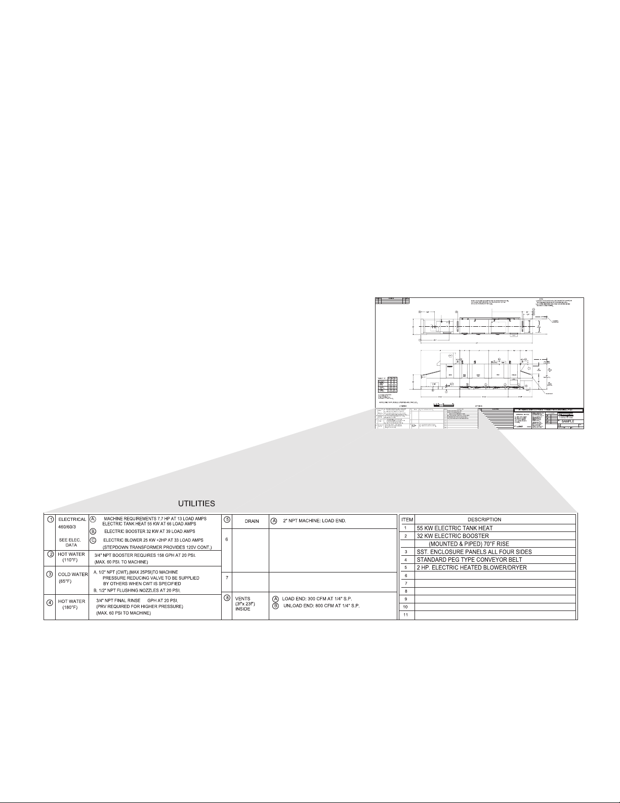
Plumbing and Electrical Diagram, (P & E)
1. The dishwasher P&E is a documented drawing that contains the critical data for the
proper construction and utility connections for the dishwasher.
2. The P&E was reviewed and approved by all authorized persons prior to shipment.
3. The sample diagram below illustrates the format and presentation of the data necessary
to connect the dishwasher.
21

Blank Page
This Page
Intentionally
Left Blank
22

(machine viewed from front)
Installation Instructions
1. The illustrations below are an example machine, your machine may be different.
Plan View
(machine viewed from above)
Installation
UNLOAD END "B"
RINSE
WASH/RINSE "C"
RINSE "C1" WASH "C1"
POWER
RINSE
DIRECTION OF
OPERATION
Elevation View
POWER
WASH
LOAD END "A"
PREWASHFINAL
23

Unpack and Place
Installation Instructions
Unpack and Place
Unpack and place
1. Upright conveyor dishwashers ship in
sections. Each section comes wrapped
in a protective covering and secured
toa wooden pallet. Labels note the
totalnumber of sections shipped, such
as 1 of 4.
Accessories
2. Check the shipment for damage
immediately upon receipt. Save all
packing materials and pallets, then
contact a supervisor, the equipment
dealer, and the factory to report the
damage.
3. Fasteners, curtains, panels and other
pieces are packing in cardboard boxes
and secured to the wash/rinse section of
the machine. Inventory these parts and
report shortages to a supervisor, then
store the parts in a secure location.
CAUTION:
Standard 36" doorways often measure
less than 35" in width.
Shipping pallets measure 48" wide.
24
Fasteners

4 Inspect the route that sections
must travel if the shipment was
not delivered to the dishwashing
room. Measure allpassageways
and doors before moving the
dishwasher.
IMPORTANT
Check the utilities early
Incorrect voltage, hot water supply,
or steam piping may delay the
completion of the installation
Unpack and Place
Installation Instructions
Unpack and Place
5. Piping on the rear wall of the
dishwasher may be removed to
allow the dishwasher to pass
through narrow openings if
necessary.
6. Compare the location of the site
utilities with the Plumbing and
Electrical Connection Diagram,
(P&E).
CAUTION
Use extreme care when lifting
a section off its pallet to prevent
damage to the dishwasher.
25

Order of Assembly
Installation Instructions
Order of Assembly
7. Next, compare the site utilities with the utility connections
on the dishwasher.
The utility locations and ratings of the must match
the dishwasher when it is re-assembled in its
permanent location.
Contact a supervisor immediately if a utility location
does not match the
dishwasher.
8. Checkoorstability.Flooringmustsupporttheweightofthe
dishwasher without bowing when weight is applied.
Tiledoorsmayfractureifloadsaredroppedonordrugacross
its surface.
9. Move the palleted sections near their permanent locations.
Remove protective coverings, shipping straps, brackets and
palletized accessories.
10. Inspect the underside of each section, (below the base) and
note the position of piping, valves, and other components that
may be in the way
11. Carefully lift each section off the pallet. Screw the adjustable
bullet-feet in as far as possible, then lower the section to the
nishedoor.
26

Order of Assembly
Installation Instructions
Order of Assembly
12. The illustration above shows the correct placement of the sections.
13. The recommended spacing between sections is 2 feet. Of course, the size of your dishroom
dictates the actual section spacing.
14. Study the illustration above. Note that each section name also contains a designated letter,
(A, B, C, E).
15. The illustrated dishwasher is a right-to-left, (R-L)congurationwhichindicatesthatsoiled
wares enter on the right and exit on the left. A left-to-right, (L-R), dishwasher is the reverse
of a R-L dishwasher.
16. The "E" or Eco-rinse section is an option and may not be a part of your installation.The
dashed lines between the "C" and "E" sections indicate that the "E" section usually ships
as part of "C" section.
17. The "C" section ships as a single assy in 4, 6, or 8 ft. lengths.
18. The Order of Assembly should start with the "C" section; however, it is okay to start with
the "B" section if the plumber is ready to make the hot water and steam connections.
27

Section Assembly
Installation Instructions
Section Assembly
19. Remove the shipping braces from
the sections.
20. Identify the location of piping
between the sections.
21. Check the height of each section
and determine which section is the
highestduetooorvariations.
22. Set the "C" section and adjust to its
minimum height.
23. Level the "C" section side to side
and front to back in several places
with a bubble level.
24. The remaining sections are leveled
in relation to "C" section.
Do not adjust the "C" section
too high.
25. Apply a 1/4" bead of FOOD
GRADE sealant to the foam
gaskets on each section.
APPROVED SEALANT WAS SUPPLIED IN
THE HARDWARE KIT.
DO NOT SUBSTITUTE ANOTHER
TYPE OF SEALANT.
26. Move the next section close to
the "C". Adjust the feet of this
section to align the 20 bolt holes
around the hood.
27. Slide the connecting hoses and
clamps on drain pipes and crossowpipes.Donottighten
at this time.
28
28. Level each section side to side
and front to back making sure
the section connecting bolt holes
align.

29. Make sure the sections are
adjusted to the same height.
30. Check the alignment of the
conveyor tracks inside the
machine and adjust tracks if
necessary. Tracks should align
if the sections are level.
31. Bolt all the HOOD sections
together with twenty (20), 5/1618 X 3/4" bolts, lockwashers and
nuts included in the hardware kit.
32. Tighten the hood bolts in a
cross-pattern to pull the sections
together.
Section Assembly
Installation Instructions
Section Assembly
33. Silicon sealant should squeeze
out of the section joints.
34. Apply a 1/2" bead of Foodgrade
sealant in the bottom of the clip.
35. Invert the clip and slide it over
the section joint
36. Bolt the clip securely in place.
29

Section Assembly
Installation Instructions
Conveyor Belt Installation
Beginning with S/N J11062899 and above
1. Remove the key from the conveyor drive
sprocket.
2. Start at the unload end of the machine
and pull the conveyor belt around the end
sprockets until approximately 1.5 feet/76.2
cm of belt rests on the upper track of the
dishwasher.
3. Pull a section of belt to the next section along
the upper track into the unload end.
4. Join the belt sections together by feeding a
conveyor rod through the links, spacers, and
rollers. Install a cotter pin on each end of the
rod to secure the assembly.
5. Use an assembled rod section on the belt as
a guide for the placement of the spacers, etc.,
continue this procedure until the conveyor belt
is assembled in a complete loop.
Connect the conveyor belt sections with
a rod, spacers, and washers included
in the hardware kit.
30
Remove the key from the conveyor drive sprocket.

Section Assembly
Roller seated
in sprocket
Steel links do not
rub sprocket
Conveyor Belt Installation
The take-up assemblies are located on either
side of the load end conveyor shaft as shown in (A).
Adjust the conveyor belt tension at the load end. Loosen
the adjusting bolt locknuts then turn the adjusting bolts CW
to tighten the belt.
Make sure the belt tension is even on both sides.
Check the slack of the lower portion of the belt. The lower
belt must not sag.
Continue to adjust belt tension as you manually remove
lower belt slack until the lower slack is minimized.
Check the belt tension by lifting the upper conveyor belt
at the load end of the dishwasher as shown in (B).
The proper belt tension is achieved when the top of the
conveyor belt rods are even with the top of the belt
access hole as shown in (C).
DO NOT OVERTIGHTEN THE BELT.
Belt Access Hole
A
Tighten the adjusting bolt locknuts on each take-up
assembly to hold the belt adjustment.
Check that the conveyor belt tracks evenly on all
of the conveyor drive sprockets during operation and
adjust the take-up assemblies as required
as shown in (D).
Proper tracking requires that the rollers seat evenly
in the conveyor belt drive sprockets. The metal links
on the conveyor belt must not rub the sides of the
belt sprockets as shown in (E).
B
C
E
D
31

Section Assemby
Installation Instructions
Conveyor Drive
Beginning with S/N J11062899 and above
There are two conveyor drive designs.
Therstisthestandarddrivecomprisedofa
gear box, drive belt motor and chain connected
to the conveyor drive shaft.
The second design is variable speed solid-state
electronic speed control, a variable speed motor
and a chain connected to the conveyor drive
shaft.
Variable Frequency Drive (VFD) Conveyor Drive Motor
The conveyor drive is equipped with anti-jam protection and a reversing switch if an object
becomes jammed in the conveyor. This anti-jam mechanism shuts the conveyor drive off to
prevent damage to the conveyor belt. The anti-jam switch is adjusted at the factory and should not
require adjustment.
Standard Single Speed Conveyor Drive
Anti-jam Swith Operation
The anti-jam switch assembly consists of a base mounting bracket, a limit switch with a mounting
bracket, and a spring loaded tensioner arm with a sprocket. A reverse jog switch button is always
used in conjunction with the anti-jam switch. The tensioner arm with the sprocket is positioned on
the drive side of the drive chain.
When a jam occurs, the drive chain tightens, causing it to straighten changing the position of the
sprocket attached to the tensioner arm. When the sprocket position changes, the tensioner arm
rotates away from the button on the anti-jam switch causing it to open.
When the switch opens, all power to drive motor is disconnected stopping the forward motion of
the conveyor. The drive will not work in the forward direction as long as the anti-jam switch is
in the open position.
32

Section Assemby
Reverse Jog Switch Operation
The Single Speed Reverse Jog operates under the following conditions:
a) When the power is on and the anti-jam switch is open due to a conveyor jam.
b) When the power is on and the conveyor was stopped via the "STOP". The "START" switch
must be pressed to restart the forward motion of the conveyor.
c) If the reverse jog switch is pressed while the conveyor is moving forward, the forward motion
will stop as long as the switch is pressed. Releasing the switch will restart the belt forward
motion.
d) If the conveyor is stopped by the shut-off shelf, the "STOP" must be pressed before the reverse
switch will work.
The VFD Reverse Jog operates under the
following conditions:
a) When the VFD is powered on regardless if the
machine power is off.
b) If the button is pressed when the conveyor
is moving forward, the conveyor will run
in reverse as long as the button is pressed;
releasing the button returns the forward motion
of the belt.
c) When the anti-jam switch is open and the
reverse button is pressed, the conveyor
will run in reverse as long as the button is
pressed. Releasing the button stops the
conveyor. The START button must be
pressed to restart the conveyor.
d) The reverse button will work if the belt was
stopped by the shut-off shelf.
Reverse Jog Switch
Anti-Jam Switch Adjustments
The anti-jam switch has three adjustments.
Refer to the letters in the photo at right:
A. The base mounting bracket has horizontal
slots for positioning the tensioner arm sprocket
against the drive chain. This is a factory setting
and should not require changing.
B. The limit switch bracket has vertical slots to
adjust the switch up and down. Raising the
switch reduces the switch reaction time,
lowering it increases the reaction time.
C. The tensioner arm spring sets the amount
of force required to operate the jam switch. The
tighter the spring the more load it takes to
operate the switch and stop the conveyor.
C
A
B
Anti-jam Switch
33

Section Assemby
Installation Instructions
Section Assembly
21. The Installation Supervisor must
inspect the position, level and
proper connection of the piping
connections.
22. Steam supply and condensate
unions must be tight.
23. Drain piping must be checked.
24. Cross-owhosesmustbe
inspected and clamps tightened.
25. Flushing nozzle piping on the
load end must be inspected.
34

26. Checkandtightenthellpiping
compressionttings.
27. Make sure solenoid coils are positioned
correctly on the valve assemblies.
28. Vent stacks must be placed on the hood
with vent handles facing the front
of the dishwasher.
Section Assemby
Installation Instructions
Section Assembly
29. Panels must be rechecked for missing
parts, and the location numbers checked
with the numbers located on the
dishwasher.
30. Tanks must be checked for debris and
metal tailings must be vacuumed out of
the machine.
31. Curtains must be installed. Install
thecurtains. Long curtains hang in hooks
on each end of the machine. Short
curtains hang in hooks on the inside of
the machine.
32. Scrap screens, scrap baskets must be
checked and installed in the dishwasher.
35

Section Assemby
Installation Instructions
Optional Blower Dryer Assembly
1. The blower dryer comes in electric or
steam.
2. It ships on a separate pallet.
The vent cowl and mounting hardware
are included in the
accessories box and hardware
kit.
3. Lift the blower dryer off the pallet
with a forklift and place on the
end of the unload section.
If a forklift is not available, then
four (4) men are needed to lift
and install the unit manually.
4. Bolt the blower dryer in place using the
5/16-18X3/4"bolts,atwashers,and
lock washers from the hardware kit.
5. Fasten the vent cowl on the discharge
end of the blower dryer using the 1/4-
20plainnuts,atwashers,andlock
washers from the hardware kit.
REFER TO THE BLOWER-
DRYER SERVICE MANUAL
P/N 114316
SHIPPED WITH THE
BLOWER-DRYER
ASSEMBLY
FOR COMPLETE
INSTALLATION
INSTRUCTIONS.
6. Connecttheex-titeconduit
to the junction box located at
the rear of the dishwasher.
7. Match wire numbers in the junction box
and connect with wire nuts.
8. Close the junction box.
9. Install the cowl to the end of the
blower dryer.
36

Connect the dishwasher internal electric wiring
1. Wires,ex-tite,andsomecomponentswere
disconnected and pulled back to
each section, then junction boxes were
closed.
2. Openalljunctionboxes,identifytheex-tite
conduit connections, (A)
roll-out wire bundles, (B), and match
wire numbers attached on wires, (C).
3. Connecttheex-titeconduittotheir
associated junction boxes.
Section Assemby
Installation Instructions
Section Assembly
4. Connect matching wires using the
supplied wire nut connectors, (D)
included in the hardware kit.
5. Connect #2 and any white wires
together. All of these wires are
neutral returns.
6. Close all junction boxes.
37

Section Assemby
Installation Instructions
Section Assembly - Seal Joint Sections
1. Section joints must be sealed
with foodgrade silicon sealant.
2. Mask the joint edges with
a quick-release masking tape.
3. Apply a 1/8" bead of Foodgrade
silicon sealant. Apply moderate
pressure on the gun to ensure the
sealantllsthejoint.
4. Wait 45-seconds for the sealant
tormslightly.Thenwipethejoint
with a damp cloth.
Do not wait longer than 1 minute for
thesealanttorm.Thesealant
will not wipe correctly.
5. If the sealant dries longer than
1 minute, DO NOT try to wipe
the joint. Allow the sealant 30
minutes to dry, then cut the
sealant out of the joint and
begin again.
6. Wait 10-seconds after wiping the
joint, then remove the masking
tape.
7. Continue sealing the joints.
38
DO NOT SEAL more than
one joint at a time. The sealant
will dry faster than you can
work the joint.

8. Study the photos on the right. The top
photo shows a correctly sealed joint.
9. The stainless steel must be wiped with
Isopropyl alcohol to remove dust, oil
lm,andothercontaminants.
Section Assemby
Installation Instructions
Section Assembly - Seal Joint Sections
10. Notethatthejointislledpresenting
an even transition between sections.
11. The sealant is applied past the top
radius of the joint presenting a uniform
ll.
12.. Study the lower sealed joint. This
joint did not have enough sealant
applied and therefore presents a
crevasse where soils may be
trapped.
13. Practice this procedure on a
hidden joint if you experience
problems with the procedure.
39

Supply Connections
MACHINE ELECTRICAL CONNECTION
Installation Instructions
Supply Connections - Main Incoming Power
The Main incoming power to the dishwasher
is made at the top of machine in the control
cabinet.
The electrician must connect the power supply
in accordance with the data stamped on the
Machine Electrical Connection Plate.
This data is the ultimate authority and is not
superseded by any other data supplied in
print, or conveyed verbally.
WARNING:
Electrical and grounding connections
must comply with the National Electrical
Code and/or Local Electrical Codes.
WARNING:
When working on the dishwasher,
disconnect the electric service and
place a tag at the disconnect switch
to indicate work is being done on that
circuit.
Note:
Aqualiedelectricianmustcomparethe
electrical power supply with the machine
electricalspecicationsstamped
on the MACHINE ELECTRICAL
CONNECTION PLATE located inside
the control cabinet before connecting
to the incoming service at a fused
disconnect switch.
40

IMPORTANT
Main utility supply connections must
be performed by licenced tradesmen who abide
by local building, health and sanitation codes or
national codes in the absence of local codes.
THE MAIN INCOMING HOT WATER AND STEAM
SUPPLY CONNECTIONS ARE MADE
IN THE LOWER PART OF "D" SECTION
Supply Connections
Installation Instructions
Supply Connections - Water and Steam
ATTENTION INSTALLERS AND SUPERVISORS
REFER TO THE PLUMBING & ELECTRICAL
CONNECTION DIAGRAM FOR THE LOCATION
AND SIZE OF ALL UTILITIES.
BUILDING VENTILATION CONNECTIONS
ARE MADE AT THE TOP OF THE "A" AND "D"
SECTIONS.
BUILDING VENTS MUST ALIGN WITH THE
DISHWASHER CENTER-LINE AND MATCH THE
SIZE OF THE DISHWASHER VENT DUCTS.
Hot water connection
Steam and condensate connection
Drain Connection
41

Supply Connections
SIGNAL ONLY
VENT FAN
COMMON
COMMON
120V
DETERGENT
120V
RINSE AID
120V
Installation Instructions
Supply Connections - Chemical Dispensers
Chemical dispensing systems are supplied by others.
A connection point for detergent, and rinse-aid signals is provided in the
in the top-mounted control cabinet.
42

Supply Connections
Installation Instructions
Initial Start-up
Perform the following checks and adjustments before placing the machine into service.
• Check the interior of the machine and remove any foreign material.
• Check the exterior of the machine — make sure that the conveyor belt is free of tape
and foreign material.
Bafes –
Tankbafesredirecttheowofwaterfromthesprayarmsystemsbackintothetanks.
Thispreventswaterlossandkeepsthewash,rinse,andnalrinsewaterintheproper
tank.Checkthebafes—makesurethattheyareinstalledandpositionedcorrectly.
Close the tank drain valves along the lower front of the machine.
Open the water supply valves. Check for leaks and take corrective action as required.
Open the steam supply valves (if applicable). Check for leaks and take corrective
action if required.
Turn the main power on at the breaker panel or fused disconnect switch.
Machine main power
Electric booster main power (if applicable)
Flip the Power Switch on the frontof the Control Cabinet to the "ON" position.
The Red power on light will illuminate.
Themachinewillbegintollwithwater.
Allowthemachinetocompletelyllwithwater.
The water will shut off automatically.
Check for leaks and take corrective action if required.
Monitor the tank thermometers for the proper temperature reading.
Allowsufcienttimeforthetankheattoreachoperatingtemperature.
Move the conveyor shut-off shelf located at the end of the unload section toward the
machine. This resets the automatic conveyor stop system.
When an object on the conveyor contacts the shut-off shelf, the conveyor stops.
Press the GREEN start button on the front of the control cabinet.
43

Initial Start-up
Installation Instructions
Initial Start-up
Check the direction of rotation of the conveyor belt by observing the direction
arrow decal on the large conveyor drive sprocket. The sprocket is located on
the side of the unload section.
If rotation direction is incorrect, reverse wires L1 and L2 on the disconnect
switch side of the main electrical connection terminal block located inside the
control cabinet.
Each temperature gauge is marked with its proper operating range.
Check the Energy Sentinel (idle pump shut-off) by placing a tray or dish on
the moving conveyor belt.
The pumps will start as the object enters the tunnel of the machine.
Theoptionalecono-rinsepumpstartswiththenalrinse.
Check pump motor rotation, CW when viewed from the rear of motor.
44

Initial Start -up
Checkthenalrinsetemperatureastheobjectentersthenalrinsearea.
The Final rinse temperature must be 180-195°F.
Adjust the temperature of the incoming water supply if necessary.
Adjust the booster thermostat setting if necessary.
ChecktheFinalrinsewaterpressureastheobjectentersthenalrinsearea.
Thenalrinsepressuremustbe20-22PSI.
Adjust the Pressure Reducing Valve setting if necessary.
Checkthatthepumpsandnalrinseshut-offbeforetheobjectreachesthe
conveyor shut-off shelf.
Check that the conveyor belt stops when the object pushes the conveyor shut-off
shelf.
Move the shut-off shelf toward the tunnel of the machine. The conveyor belt will
start moving again.
Push the RED stop button. The conveyor belt will stop moving.
Flip the power switch on the control cabinet to OFF. The red power light will go out.
Openallthedrainvalvesandcheckthatthehousedrainscanhandletheow.
Removeanyprotectivelmfromthestainlesssteelandinstallthesidepanelsand
chain guard.
Check the curtains for correct placement in the machine.
BesuretheshortapsoftheLongCurtainsfacetheloadendofthemachine.
Check the spray pipes.
Be sure the spray pipe gasket is installed on the end of spray pipe before
installing.
Spray pipes are installed by inserting the pipe into the coupler and turning 1/4 turn
clockwise.
Check the scrap screens.
Install any scrap basket covers.
Check that the conveyor shut-off shelf is pushed toward the machine tunnel.
Close the drain valves, located under the base of each tank.
When the drain handle is horizontal, the valve is open.
When the valve handle is vertical, the valve is closed
Check the detergent and rinse aid supplies (supplied by others).
45

Blank Page
This Page
Intentionally
Left Blank
46

Service Replacement Parts
Illustration Page
Pump/Motor Assembly................................................................................................................................................................ 48
3HP, C3/C4 Pump Installation .................................................................................................................................................... 50
1HP, B-30 Prewash Right-Left Pump Installation ....................................................................................................................... 52
1HP, B-30 Prewash Left-Right Pump Installation ....................................................................................................................... 54
3HP, B-30 Prewash Left-Right Pump Installation ....................................................................................................................... 56
3HP, B-30 Prewash Right-Left Pump Installation ....................................................................................................................... 58
Auxiliary Rinse Right-Left Pump Installation............................................................................................................................... 60
C8 Wash/Rinse Wash System Installation ................................................................................................................................. 62
1HP 30" Prewash Right-Left Wash System Installation ............................................................................................................. 64
1HP 30" Prewash Left-Right Wash System Installation ............................................................................................................. 66
C4 Single Tank Wash System Installation .................................................................................................................................. 68
C6 Wash/Rinse Wash System Installation ................................................................................................................................. 70
C4 Wash without Scrap Basket Electric Tank Heat Installation .................................................................................................. 72
C4 Rinse without Scrap Basket Electric Tank Heat Installation .................................................................................................. 74
C4 Wash with Scrap Basket Electric Tank Heat Installation ....................................................................................................... 76
C4 Rinse with Scrap Basket Electric Tank Heat Installation ....................................................................................................... 78
Auxiliary Rinse Tank Heat Installation ........................................................................................................................................ 80
Electric Booster Element Congurations .................................................................................................................................... 82-87
Electric Booster Installation ........................................................................................................................................................ 88
Float Switches ............................................................................................................................................................................ 90
Final Rinse Installation EUCC8/EUCCW8.................................................................................................................................. 92
Final Rinse Installation C4/C6 EUCC/EUCCW .......................................................................................................................... 94
Auxiliary Rinse Installation EUCC/EUCCW ................................................................................................................................ 96
Cold Water Fill Piping Sub-assembly ......................................................................................................................................... 100
Electric Booster Fill Piping (Prior to S/N J10012728) ................................................................................................................. 102
Electric Booster Fill Piping (Beginning with S/N J10012728 and above) ................................................................................... 104
Fill Piping - No Booster (Prior to S/N J10012728) ...................................................................................................................... 106
Fill Piping - No Booster (Beginning with S/N J10012728 and above) ........................................................................................ 108
#120-1 Steam Booster Installation RL ........................................................................................................................................ 110
#120-1 Steam Booster Assembly RL 40-70°F ............................................................................................................................ 112
#120-1 Steam Booster Installation LR ........................................................................................................................................ 116
#120-1 Steam Booster Assembly LR 40-70°F ............................................................................................................................ 118
Steam Coil Heat Installation C4 Wash, Rinse 15-30 PSI ........................................................................................................... 122
Steam Coil Heat Installation C3 Wash, Rinse 15-30 PSI ........................................................................................................... 124
Steam Coil Heat Installation Auxiliary, 15-30 PSI ....................................................................................................................... 128
Steam Injector Heat Installation C4/C8, 15-30 PSI .................................................................................................................... 132
Steam Injector Heat Installation Auxiliary Rinse RL ................................................................................................................... 136
Drain Installation B-30 Prewash RL ............................................................................................................................................ 138
Drain Installation B-30 Prewash LR............................................................................................................................................ 140
Drain Installation C4 Wash, Rinse .............................................................................................................................................. 142
Drain Installation Auxiliary LR ..................................................................................................................................................... 144
Drain Installation D5 Unload ....................................................................................................................................................... 146
Drain Installation B4 Prewash RL ............................................................................................................................................... 148
Drain Installation B4 Prewash LR ............................................................................................................................................... 150
Drain Installation C3 Wash, Rinse .............................................................................................................................................. 152
Electric Eyes, Start-Stop Station, Flushing Nozzles ................................................................................................................... 154
Idle Shaft Assembly .................................................................................................................................................................... 156
Drive Assembly, Prior to S/N J11062899 ................................................................................................................................... 158
EUCCW Peg Belt and Peg Belt with Upper Rod Conveyor Belts............................................................................................... 160
EUCCW Flat and Insulated Conveyor Belts ............................................................................................................................... 162
EUCCW Stainless Steel Conveyor Belt...................................................................................................................................... 164
EUCC Peg Belt and Peg Belt with Upper Rod Conveyor Belts .................................................................................................. 166
EUCC Flat and Insulated Tray Belts ........................................................................................................................................... 168
EUCC Stainless Steel Conveyor Belt ......................................................................................................................................... 170
Vent Cowl Installation ................................................................................................................................................................. 172
Curtain Locations.....................................................................................................................................................................174-185
Tank Bafes EUCC/EUCCW
Control Cabinet (From S/N J2098 up to J08102541) ................................................................................................................. 188
Control Cabinet (From S/N J08012541 up to J10012728) ......................................................................................................... 192
Control Cabinet (Beginning with S/N J10012728 and above) .................................................................................................... 196
Standard 30" Door Assembly ..................................................................................................................................................... 200
Split Door Assembly ................................................................................................................................................................... 202
Swing-out Door Assembly - B-30 R-L/E2 L-R............................................................................................................................. 204
Swing-out Door Assembly - E2 R-L/ B-30 L-R............................................................................................................................ 206
Swing-out Door Assembly - C4................................................................................................................................................... 208
Scrap Screens ............................................................................................................................................................................ 210
Conveyor Shut-off Shelf ....................................................................................................................................... 211
Drive Assembly, Beginning with S/N J11062899 and above ................................................................................ 212
L-R Anti-jam and Tensioner Assembly .................................................................................................................. 213
R-L Anti-jam and Tensioner Assembly .................................................................................................................. 214
Reverse Jog Switch Assembly ............................................................................................................................. 215
Hot Water Coil for C3, EUCCW ............................................................................................................................ 216
...................................................................................................................................................... 186
47

Pump/Motor Assembly
48

Pump/Motor Assembly
1 100735 HEX HEAD,1/4-20 X 5/8 SST1
2 100736 HEX HEAD,1/4-20 X 3/4 SST10
3 100754 SCREW,FLAT HEAD,10-32 X 1/2 SST3
4 102500 PLUG,1/4"NPT SQ.HEAD,BRASS3
5 102504 PLUG,1/2"NPT SQ.HEAD,BRASS1
6 106407 WASHER,LOCK,3/8 SPLIT,SST4
7 106482 WASHER,LOCK,1/4 SPLIT,SST11
8 107690 HEX PLAIN JAM NUT,3/8-16 SST4
9 109654 SLINGER, JET PUMP1
10 110247 HEX PLAIN JAM NUT,7/16-14 SST1
11 110248WASHER,FLAT,.440x.750x.043 SST1
12 110270WASHER,LOCK,CSK EXTERNAL TOOTH,#10 3
13 110424MOTOR,3HP 3PH, MV JET PUMP 1
14 110734 STUD,3/8-16 X 1 3/8 LG.SST,PUMP4
15 111111 SEAL ASSY,CI PUMP1
16 111941 GASKET,PUMP VOLUTE,.0085 THICK1
17 111942 GASKET,PUMP VOLUTE,.015 THICK1
18 111943 GASKET,PUMP VOLUTE,.032 THICK1
19 112338 GASKET,PUMP SUCTION FLANGE1
20 113120 IMPELLER,3HP SST,MACHINED B4 /C3 / C4 EUCCW 1
--- 113119 IMPELLER,3HP SST,MACHINED C3 EUCC 1
--- --- IMPELLER,3HP SST,MACHINED B4 / C4 EUCC 1
21 113634 VOLUTE,JET PUMP,SST1
22 113635 FLANGE,JET PUMP,SST1
23 113636 SUCTION FLANGE 1
24 204460 BACKING PLATE,NG JET PUMP1
113263 MOTOR, 3HP, 575V/60/3
49

1
2
3
4
6
7
8
9
10
11
12
13
1
3
4
4
4
7
5
3HP, B4/C3/C4 Pump Installation
50

3HP, C3/C4 Pump Installation
1 100154 HEX PLAIN NUT,5/16-18 SST10
2 100739 HEX HEAD,5/16-18 X 3/4 SST2
3 100740 HEX HEAD,5/16-18 X 1 SS T8
4 102376 WASHER,FLAT,5/16 x 3/4 x.06 SST16
5 104203 CLAMP,HOSE,M52,71/95,SST GEAR TYPE2
6 104640 GASKET,PUMP SUCTION RACK/CC/UC1
7 106013 WASHER,LOCK,5/16 SPLIT,SST10
8110372 HOSE,PUMP SUCTION,UC1
9 313300 FLANGE WELD,PUMP SUCTION,UC1
10 319742 HOOD WELDMENT,PUMP SUCTION,UC 1
11 319743 PLATE,PUMP SUCTION HOOD 1
12 320918 SUPPORT,PUMP MOTOR,C3 NUCCW1
13 405923 PUMP ASSY,3HP MV 3PH, UC B4 / C3 / C4 EUCCW 1
405922 PUM
415920 PUMP ASSY, 3HP, 575/60/3 LH, UC B4/C3 EUCCW
415921 PUMP ASSY, 3HP, 575/60/3 RH, UC B4/C4 EUCC
P ASSY,3HP MV 3PH, UC C3 EUCC 1
---
---
--- PUMP ASSY,3HP MV 3PH, UC B4 / C4 EUCC 1
51

1HP, B-30 Prewash Right-Left Pump Installation 53 1HP, B-30 Prewash Right-Left Pump Installation
16
14
3
4
15
4
3
4
USED ON MACHINES
WITH LOAD FLUSHING
SYSTEM
11
10
8
6
5
5
9
4
7
1
1
7
1
7
4
52
12
13
3

1 100154 HEX PLAIN NUT,5/16-18 SST12
2 100739 HEX HEAD,5/16-18 X 3/4 SST4
3 100740 HEX HEAD,5/16-18 X 1 SS
T
8
4 102376 WASHER,FLAT,5/16x3/4x.06 SST20
5 104203 CLAMP,HOSE,SST GEAR TYPE2
6 104640 GASKET,PUMP SUCTION RACK/CC/UC1
7 106013 WASHER,LOCK,5/16 SPLIT,SST12
8 109926 FITTING,COMPRESSION,5/8OD X 1/2"MNPT,ELL,BRASS1
9110372 HOSE,PUMP SUCTION,UC1
10 205192 TUBE,1/2"COPPER X 3.00"LG 1
11 313300 FLANGE WELD,PUMP SUCTION,UC1
12 319742 HOOD WELDMENT,PUMP SUCTION,UC1
13 319743 PLATE,PUMP SUCTION HOOD1
14 322150 SUPPORT,PUMP MOTOR,B2 NUCCW1
15 329618 BRACKET,PUMP SUPPORT,B-30 W/A3 1
16 405919-120 PUMP ASSY,1HP MV 3PH 1
415917 PUMP ASSY, 1HP, 575/60/3, UC

1
2
3
4
6
7
9
11
12
13
14
15
16
1
1
3
4
4
4
5
7
7
8
10
USED ON MACHINES
WITH LOAD FLUSHING SYSTEM
5
1HP, B-30 Prewash Left-Right Pump Installation 55 1HP, B-30 Prewash Left-Right Pump Installation
54

1 100154 HEX PLAIN NUT,5/16-18 SST12
2 100739 HEX HEAD,5/16-18 X 3/4 SST4
3 100740 HEX HEAD,5/16-18 X 1 SST8
4 102376 WASHER,FLAT,5/16x3/4x.06 SST20
5 104203 CLAMP,HOSE,M52,71/95,SST GEAR TYPE2
6 104640 GASKET,PUMP SUCTION RACK/CC/UC1
7 106013 WASHER,LOCK,5/16 SPLIT,SST 12
8 109926 FITTING,COMPRESSION,5/8OD X 1/2"MNPT,ELL,BRASS1
9110372 HOSE,PUMP SUCTION,UC1
10 205192 TUBE,1/2"COPPER X 3.00"LG 1
11 313300 FLANGE WELD,PUMP SUCTION,UC1
12 319742 HOOD WELDMENT,PUMP SUCTION,UC1
13 319743 PLATE,PUMP SUCTION HOOD1
14 322150 SUPPORT,PUMP MOTOR,B2 NUCCW1
15 329618 BRACKET,PUMP SUPPORT,B-30 W/A3 1
16 405919 PUMP ASSY,1HP MV 3PH, UC 1
415917 PUMP ASSY, 1HP, 575/60/3

1
2
3
4
6
7
9
11
12
13
14
15
16
1
1
3
4
4
4
4
7
7
8
10
USED ON MACHINES
WITH LOAD FLUSHING SYSTEM
5
5
3HP, B-30 Prewash Left-Right Pump Installation 57 3HP, B-30 Prewash Left-Right Pump Installation
56

1 100154 HEX PLAIN NUT,5/16-18 SST 12
2 100739
HEX HEAD,5/16-18 X 3/4 SST 4
3 100740
HEX HEAD,5/16-18 X 1 SST
8
4 102376 WASHER,FLAT,5/16x3/4x.06 SST 20
5 104203 CLAMP,HOSE,M52,71/95,SST GEAR TYPE 2
6 104640 GASKET,PUMP SUCTION RACK/CC/UC 1
7 106013 WASHER,LOCK,5/16 SPLIT,SST 12
8 109926 FITTING,COMPRESSION,5/8OD X 1/2"MNPT,ELL,BRASS 1
9110372 HOSE,PUMP SUCTION,UC 1
10 205192 TUBE,1/2"COPPER X 3.00"LG 1
11 313300 FLANGE WELD,PUMP SUCTION,UC 1
12 319742 HOOD WELDMENT,PUMP SUCTION,UC 1
13 319743 PLATE,PUMP SUCTION HOOD 1
14 322150 SUPPORT,PUMP MOTOR,B2 NUCCW 1
15 329618 BRACKET,PUMP SUPPORT,B-30 W/A3 1
16 405923 PUMP ASSY,3HP MV 3PH, UC 1
415920 PUMP ASSY, 3HP, 575/60/3 LH, UC B4/C3 EUCCW
415921 PUMP ASSY, 3HP, 575/60/3 RH, UC B4/C3 EUCC

1
3
4
6
7
9
11
12
13
14
15
16
1
1
3
3
4
4
4
4
7
7
8
10
USED ON MACHINES
WITH LOAD FLUSHING
SYSTEM
5
5
3HP, B-30 Prewash Right-Left Pump Installation 59 3HP, B-30 Prewash Right-Left Pump Installation
58

1 100154 HEX PLAIN NUT,5/16-18 SST12
2 100739 HEX HEAD,5/16-18 X 3/4 SST4
3 100740 HEX HEAD,5/16-18 X 1 SST8
4 102376 WASHER,FLAT,5/16x3/4x.06 SST20
5 104203 CLAMP,HOSE,M52,71/95,SST GEAR TYPE2
6 104640 GASKET,PUMP SUCTION RACK/CC/UC1
7 106013 WASHER,LOCK,5/16 SPLIT,SST 12
8 109926 FITTING,COMPRESSION,5/8OD X 1/2"MNPT,ELL,BRASS1
9110372 HOSE,PUMP SUCTION,UC1
10 205192 TUBE,1/2"COPPER X 3.00"LG 1
11 313300 FLANGE WELD,PUMP SUCTION,UC1
12 319742 HOOD WELDMENT,PUMP SUCTION,UC1
13 319743 PLATE,PUMP SUCTION HOOD1
14 322150 SUPPORT,PUMP MOTOR,B2 NUCCW1
15 329618 BRACKET,PUMP SUPPORT,B-30 W/A3 1
16 405923-120 PUMP ASSY,3HP MV 3PH, UC 1
405920 PUMP ASSY, 3HP, 575/60/3 LH, UC B4/C3 EUCCW
405921 PUMP ASSY, 3HP, 575/60/3 RH, UC B4/C3 EUCCW

R-L SHOWN
1
2
3
4
5
6
7
9
10
11
8
8
12
13
14
15
16
17
18
6
9
Auxiliary Rinse Right-Left Pump Installation
60

Auxiliary Rinse Right-Left Pump Installation
1 100023 STREET ELBOW,3/4"NPT X 90,SST1
2 100051 NIPPLE,3/4"NPT X CLOSE,SST1
3 100154 HEX PLAIN NUT,5/16-18 SST4
4 100739 HEX HEAD,5/16-18 X 3/4 SST4
5 100740 HEX HEAD,5/16-18 X 1 SST4
6 102376 WASHER,FLAT,5/16x3/4x.06 SST8
7 102554 UNION,3/4"NPT, SST1
8 105993 CLAMP,HOSE,M20,19/44,SST GEAR TYPE4
9 106013 WASHER,LOCK,5/16 SPLIT,SST 8
10 108345 GASKET,HEATER/STANDPIPE1
11 114020 HOSE, 1 1/8"ID x 2 3/4" x 3/16" WALL 1
12 114199 PUMP ASSY AUXILIARY1
13 206643 HOSE,1.250 ID X 2.500 LG.EPDM 1
14 322832 HOOD WELDMENT,PUMP SUCTION,E21
15 329791 BASE DECK WELD,PUMP,E2 1
--- 0509303 KIT, PUMP BODY
KIT, SEAL AND GASKET
IMPELLER
1
--- 0510222 1
---
---
180413 1
16 329796 TUBE WELDMENT,E2 PUMP DISCHARGE EUCCW 1
330750 TUBE WELDMENT,E2 PUMP DISCHARGE EUCC 1
17 329797 FLANGE WELD,E2 PUMP SUCTION1
18 329798 PLATE,PUMP SUCTION HOOD,E2 1
111744 MOTOR, AUXILIARY, 1/4 HP, 575/60/3
452611 PUMP ASSY, AUXILIARY, 1/4 HP, 575/60/3
61

FRONT LOWER
CONVEYOR TRACK
MANIFOLD
TRACK SUPPORTS
(WELDED IN HOOD)
SUPPORT ANGLES
(WELDED IN HOOD)
1
2
4
5
6
7
8
10
12
13
14
15
16
17
18
19
20
21
22
23
24
25
26
12
14
1
3
3
5
6
11
11
5
9
27
27
C8 Wash/Rinse Wash System Installation
62

C8 Wash/Rinse Wash System Installation
1 100734 HEX HEAD,1/4-20 X 1/2 SST14
2 100755 SCREW,FLAT HEAD,1/4-20 X 1/2 SST4
3 104414 O-RING,1 X 1 1/4 X 1/8 9
4 106014 HEX ACORN PLAIN NUT,1/4-20 SST4
5 106026 WASHER,FLAT,1/4x5/8x.06 SST15
6 106482 WASHER,LOCK,1/4 SPLIT,SST14
7 108875 COTTER PIN,3/32 X 1/2 UNEVEN 1
8110858 HOSE CLAMP,HIGH PRESSURE,02561
9 111780 HOSE CLAMP,HIGH PRESSURE,02382
10 111964 HOSE CLAMP,HIGH PRESSURE,02751
11 112240 PLUG, DEBOSSED SPRAYPIPE9
12 113911 LOCKNUT,2 1/2" , NPSL, SST2
13 113984 HOSE, DISCHARGE MOLDED E1
14 114096 O-RING,2.225x.210 DIA. 2
15 202146 HOSE,1.875 ID X 5.375 LG.EPDM 1
16 206552 ROD, LATCH PIVOT,5 HOLE MANIFOLD1
17 329659 MANIFOLD WELDMENT,5 HOLE,UPPER EUCCW 1
18 329662 MANIFOLD WELDMENT,4 HOLE,LOWER EUCCW 1
19 329669 TRACK WELDMENT, LH LOWER, MANIFOLD EUCCW 1
20 329670 TRACK WELDMENT, RH LOWER, MANIFOLD EUCCW 1
21 329672 TRACK WELDMENT, LH UPPER, MANIFOLD EUCCW 1
22 329673 TRACK WELDMENT, RH UPPER, MANIFOLD EUCCW 1
--- 330632 MANIFOLD WELDMENT,5 HOLE,UPPER EUCC 1
--- 330633 MANIFOLD WELDMENT,4 HOLE,LOWER EUCC 1
--- 330644 TRACK WELDMENT, LH LOWER, MANIFOLD EUCC 1
--- 330645 TRACK WELDMENT, RH LOWER, MANIFOLD EUCC 1
--- 330641 TRACK WELDMENT, LH UPPER, MANIFOLD EUCC 1
--- 330642 TRACK WELDMENT, RH UPPER, MANIFOLD EUCC 1
23 329674 BRACKET, LOWER MANIFOLD LATCH2
24 329704 LATCH DEVP, UPPER MANIFOLD,5 HOLE1
25 330680 STANDPIPE WELDMENT, C4 1
26 330838 TUBE, PUMP DISCHARGE, WELDMENT EUCCW1
27 114692 2
--- 330639 TUBE, PUM
GASKET, STANDPIPE
P DISCHARGE, WELDMENT EUCC1
63

1
2
3
4
5
6
7
8
10
11
12
13
14
15
16
17
29
18
19
20
21
22
23
24
25
26
27
SUPPORT ANGLES
(WELDED IN HOOD)
MANIFOLD
TRACK SUPPORTS
(WELDED IN HOOD)
FRONT LOWER
CONVEYOR TRACK
1
5
6
12
13
15
5
3
11
9
30
30
1HP 30" Prewash Right-Left Wash System Installation
64

1HP 30" Prewash Right-Left Wash System Installation
1 100734 HEX HEAD,1/4-20 X 1/2 SST14
2
100755 SCREW,FLAT HEAD,1/4-20 X 1/2 SST4
3
104414 O-RING,1 X 1 1/4 X 1/8 5
4
106014 HEX ACORN PLAIN NUT,1/4-20 SST4
5
106026 WASHER,FLAT,1/4x5/8x.06 SST15
6
106482 WASHER,LOCK,1/4 SPLIT,SST14
7
108875 COTTER PIN,3/32 X 1/2 UNEVEN 1
8
110858 HOSE CLAMP,HIGH PRESSURE,02561
9
111780 HOSE CLAMP,HIGH PRESSURE,02382
10
111964 HOSE CLAMP,HIGH PRESSURE,02751
11
112240 PLUG, DEBOSSED SPRAYPIPE5
12
113911 LOCKNUT,2 1/2" , NPSL, SST2
13
113912RETAINING RING, INTERNAL, 2" BORE2
14
113984 HOSE, DISCHARGE MOLDED E1
15
114096 O-RING,2.225x.210 DIA. 2
16
202146 HOSE,1.875 ID X 5.375 LG.EPDM 1
17
206553 ROD, LATCH PIVOT,3 HOLE MANIFOLD1
18
329669 TRACK WELDMENT, LH LOWER, MANIFOLD EUCCW 1
19
329670 TRACK WELDMENT, RH LOWER, MANIFOLD EUCCW 1
20
329672 TRACK WELDMENT, LH UPPER, MANIFOLD EUCCW 1
21
329673 TRACK WELDMENT, RH UPPER, MANIFOLD EUCCW 1
22
329674 BRACKET, LOWER MANIFOLD LATCH2
23
329696 MANIFOLD WELDMENT,3 HOLE,UPPER EUCCW 1
24
329699 MANIFOLD WELDMENT,2 HOLE,LOWER EUCCW 1
---
330644 TRACK WELDMENT, LH LOWER, MANIFOLD EUCC 1
---
330645 TRACK WELDMENT, RH LOWER, MANIFOLD EUCC 1
---
330641 TRACK WELDMENT, LH UPPER, MANIFOLD EUCC 1
---
330642 TRACK WELDMENT, RH UPPER, MANIFOLD EUCC 1
---
330637 MANIFOLD WELDMENT,3 HOLE,UPPER EUCC 1
---
330638 MANIFOLD WELDMENT,2 HOLE,LOWER EUCC 1
25
329705 LATCH DEVP, UPPER MANIFOLD,3 HOLE1
26
330308 MANIFOLD RESTRICTOR, 0.781" ID 1
27
330309 MANIFOLD RESTRICTOR, 0.531" ID 1
28
330698 STANDPIPE WELDMENT,B-30 RL 1
29
330838 TUBE, PUMP DISCHARGE, WELDMENT EUCCW1
30
114692 GASKET, STANDPIPE 2
--- 330679 TUBE, PUMP DISCHARGE, WELDMENT EUCC 1
65

1
2
3
4
5
6
7
8
10
11
12
13
14
15
16
17
29
18
19
20
21
22
23
24
25
26
27
28
SUPPORT ANGLES
(WELDED IN HOOD)
MANIFOLD
TRACK SUPPORTS
(WELDED IN HOOD)
FRONT LOWER
CONVEYOR TRACK
1
5
6
12
13
15
5
3
11
9
9
30
30
1HP 30" Prewash Left-Right Wash System Installation
66

1HP 30" Prewash Left-Right Wash System Installation
1 100734 CAP SCREW,HEX HEAD,1/4-20 X 1/2 SST14
2 100755 SCREW,FLAT HEAD,1/4-20 X 1/2 SST4
3 104414 O-RING,1 X 1 1/4 X 1/8 5
4 106014 HEX ACORN PLAIN NUT,1/4-20 SST4
5 106026 WASHER,FLAT,1/4x5/8x.06 SST15
6 106482 WASHER,LOCK,1/4 SPLIT,SST 14
7 108875 COTTER PIN,3/32 X 1/2 UNEVEN 1
8110858 HOSE CLAMP,HIGH PRESSURE,02561
9 111780 HOSE CLAMP,HIGH PRESSURE,02382
10 111964 HOSE CLAMP,HIGH PRESSURE,02751
11 112240 PLUG, DEBOSSED SPRAYPIPE 5
12 113911 LOCKNUT,2 1/2" , NPSL, SST2
13 113912RETAINING RING, INTERNAL, 2" BORE2
14 113984 HOSE, DISCHARGE MOLDED E1
15 114096 O-RING,2.225x.210 DIA. 2
16 202146 HOSE,1.875 ID X 5.375 LG.EPDM 1
17 206553 ROD, LATCH PIVOT,3 HOLE MANIFOLD1
18 329669 TRACK WELDMENT, LH LOWER, MANIFOLD EUCCW 1
19 330642 TRACK WELDMENT, RH LOWER, MANIFOLD EUCCW 1
20 329672 TRACK WELDMENT, LH UPPER, MANIFOLD EUCCW 1
21 329673 TRACK WELDMENT, RH UPPER, MANIFOLD EUCCW 1
22 329674 BRACKET, LOWER MANIFOLD LATCH2
23 329696 MANIFOLD WELDMENT,3 HOLE,UPPER EUCCW 1
24 329699 MANIFOLD WELDMENT,2 HOLE,LOWER EUCCW 1
25 329705 LATCH DEVP, UPPER MANIFOLD,3 HOLE1
26 330308 MANIFOLD RESTRICTOR, 0.781" ID 1
27 330309 MANIFOLD RESTRICTOR, 0.531" ID 1
28 330699 STANDPIPE WELDMENT,B-30 LR 1
29
30 114692 GASKET, STANDPIPE 2
330838 TUBE, PUMP DISCHARGE, WELDMENT EUCCW1
--- 329669 TRACK WELDMENT, LH LOWER, MANIFOLD EUCC 1
--- 329670 TRACK WELDMENT, RH LOWER, MANIFOLD EUCC 1
--- 330645 TRACK WELDMENT, LH UPPER, MANIFOLD EUCC 1
--- 330641 TRACK WELDMENT, RH UPPER, MANIFOLD EUCC 1
--- 330637 MANIFOLD WELDMENT,3 HOLE,UPPER EUCC 1
---
---
330638 MANIFOLD WELDMENT,2 HOLE,LOWER EUCC 1
330639 TUBE, PUMP DISCHARGE, WELDMENT EUCC1
67

1
2
4
5
6
7
8
10
12
13
14
15
16
17
18
19
20
21
22
23
24
25
26
27
28
12
15
3
3
11
11
1
5
6
5
FRONT LOWER
CONVEYOR TRACK
MANIFOLD
TRACK SUPPORTS
(WELDED IN HOOD)
SUPPORT ANGLES
(WELDED IN HOOD)
9
9
29
29
C4 Single Tank Wash System Installation
68

C4 Single Tank Wash System Installation
1 100734 HEX HEAD,1/4-20 X 1/2 SST14
2 100755 SCREW,FLAT HEAD,1/4-20 X 1/2 SST4
3 104414 O-RING,1 X 1 1/4 X 1/8 10
4 106014 HEX ACORN PLAIN NUT,1/4-20 SST4
5 106026 WASHER,FLAT,1/4x5/8x.06 SST15
6 106482 WASHER,LOCK,1/4 SPLIT,SST14
7 108875 COTTER PIN,3/32 X 1/2 UNEVEN 1
8110858 HOSE CLAMP,HIGH PRESSURE,02561
9 111780 HOSE CLAMP,HIGH PRESSURE,02382
10 111964 HOSE CLAMP,HIGH PRESSURE,02751
11 112240 PLUG, DEBOSSED SPRAYPIPE10
12 113911 LOCKNUT,2 1/2" , NPSL, SST2
13 113912RETAINING RING, INTERNAL, 2" BORE1
14 113984 HOSE, DISCHARGE MOLDED E1
15 114096 O-RING,2.225x.210 DIA. 2
16 202146 HOSE,1.875 ID X 5.375 LG.EPDM 1
17 206552 ROD, LATCH PIVOT,5 HOLE MANIFOLD1
18 329659 MANIFOLD WELDMENT,5 HOLE,UPPER EUCCW 1
19 329669 TRACK WELDMENT, LH LOWER, MANIFOLD EUCCW 1
20 329670 TRACK WELDMENT, RH LOWER, MANIFOLD EUCCW 1
21 329672 TRACK WELDMENT, LH UPPER, MANIFOLD EUCCW 1
22 329673 TRACK WELDMENT, RH UPPER, MANIFOLD EUCCW 1
--- 329659 MANIFOLD WELDMENT,5 HOLE,UPPER EUCC 1
--- 330632 TRACK WELDMENT, LH LOWER, MANIFOLD EUCC 1
--- 330644 TRACK WELDMENT, RH LOWER, MANIFOLD EUCC 1
--- 330641 TRACK WELDMENT, LH UPPER, MANIFOLD EUCC 1
--- 330642 TRACK WELDMENT, RH UPPER, MANIFOLD EUCC 1
23 329674 BRACKET, LOWER MANIFOLD LATCH2
24 329704 LATCH DEVP, UPPER MANIFOLD,5 HOLE1
25 330467 MANIFOLD WELDMENT,5 HOLE,LOWER- EUCCW 1
--- 330467 MANIFOLD WELDMENT,5 HOLE,LOWER- EUCC 1
26 330468 MANIFOLD RESTRICTOR, 1.188" ID 1
27 330680 STANDPIPE WELDMENT, C4 1
28
29 114692 GASKET, STANDPIPE
330838 TUBE, PUMP DISCHARGE, WELDMENT EUCCW1
--- 330838 TUBE, PUMP DISCHARGE, WELDMENT EUCC1
2
69

FRONT LOWER
CONVEYOR TRACK
MANIFOLD
TRACK SUPPORTS
(WELDED IN HOOD)
SUPPORT ANGLES
(WELDED IN HOOD)
1
2
4
5
6
7
8
10
12
14
15
16
17
19
26
20
21
22
23
24
25
27
29
29
28
12
9
15
1
3
3
5
6
11
11
5
13
18
C6 Wash/Rinse Wash System Installation
70

C6 Wash/Rinse Wash System Installation
1 100734 HEX HEAD,1/4-20 X 1/2 SST14
2 100755 SCREW,FLAT HEAD,1/4-20 X 1/2 SST4
3 104414 O-RING,1 X 1 1/4 X 1/8 9
4 106014 HEX ACORN PLAIN NUT,1/4-20 SST4
5 106026 WASHER,FLAT,1/4 x 5/8 x .06 SST15
6 106482 WASHER,LOCK,1/4 SPLIT,SST 14
7 108875 COTTER PIN,3/32 X 1/2 UNEVEN 1
8110858 HOSE CLAMP,HIGH PRESSURE,02561
9 111780 HOSE CLAMP,HIGH PRESSURE,02382
10 111964 HOSE CLAMP,HIGH PRESSURE,02751
11 112240 PLUG, DEBOSSED SPRAYPIPE9
12 113911 LOCKNUT,2 1/2" , NPSL, SST2
13 113912RETAINING RING, INTERNAL, 2" BORE1
14 113984 HOSE, DISCHARGE MOLDED E1
15 114096 O-RING,2.225x.210 DIA. 2
16 202146 HOSE,1.875 ID X 5.375 LG.EPDM 1
17 206552 ROD, LATCH PIVOT,5 HOLE MANIFOLD 1
18 328861 MANIFOLD RESTRICTOR, 1.5" ID 1
19 329659 MANIFOLD WELDMENT,5 HOLE,UPPER1
20 329669 TRACK WELDMENT, LH LOWER, MANIFOLD EUCCW 1
21 329670 TRACK WELDMENT, RH LOWER, MANIFOLD EUCCW 1
22 329672 TRACK WELDMENT, LH UPPER, MANIFOLD EUCCW 1
23 329673 TRACK WELDMENT, RH UPPER, MANIFOLD EUCCW 1
24 329674 BRACKET, LOWER MANIFOLD LATCH2
25 330186 LATCH DEVP, UPPER MANIFOLD,4 HOLE1
26 330467 MANIFOLD WELDMENT,5 HOLE,LOWER EUCCW 1
27 330680 STANDPIPE WELDMENT, C4 1
28
29 114692 GASKET, STANDPIPE
330838 TUBE, PUMP DISCHARGE, WELDMENT EUCCW1
--- 330639 TUBE, PUMP DISCHARGE, WELDMENT EUCC1
2
71

C4 Wash without Scrap Basket Electric Tank Heat Installation
72

C4 Wash without Scrap Basket Electric Tank Heat Installation
1 100007 SCREW,TRUSS HEAD,10-32 x 3/8 SST3
2 100109 WELD-STUD,1/4-20 X 1/2 LG.SST 2
3 100154 HEX PLAIN NUT,5/16-18 SST12
4 100198 WELD-STUD,10-32 X 1/2 LG.SST 4
5 100547 LOCKNUT,1/2" NPT,SST2
6 100740 CAP SCREW,HEX HEAD,5/16-18 X 1 SST12
7 102376 WASHER,FLAT,5/16x3/4x.06 SST24
8 106013 WASHER,LOCK,5/16 SPLIT,SST 12
9 106026 WASHER,FLAT,1/4x5/8x.06 SST2
10 106486 WASHER,LOCK,#10 SPLIT,SST4
11 107033 WASHER,FLAT,.208X.438X.047 SST4
12 107136 SCREW,HEX HEAD,10-32 x 3/8 SST4
13 107839 TANK HEATER,RICA 5KW 208V/3ph 1
13 107842 TANK HEATER,RICA 5KW 480V/3ph 1
13 111123 TANK HEATER,RICA 5KW 575V/3ph
V/3ph
V/3ph
V/3ph
V/3ph
1
13 107840 TANK HEATER,RICA 5KW 240V/3ph 1
14 107951 TANK HEATER,RICA 10KW 208
14 107844 TANK HEATER,RICA 10KW 240
14 107846
T
ANK HE
A
A
TER,RICA 10KW 480
14 111120 TANK HE TER,RICA 10KW 575
2
2
2
2
15 107966 HEX GRIP NUT,10-32 SST W/NYLON4
16 107967 HEX GRIP NUT,1/4-20 SST W/NYLON2
17 108345 GASKET,HEATER/STANDPIPE3
18 109069 THERMOSTAT,CONTROL,WITH CAPILLARY 1
19 110561 THERMOSTAT,HI-LIMIT,WITH CAPILLARY1
20 201041 WASHER,SPACER,7/8x1 3/16x1/8 NP 2
21 323430 BRACKET, THERMOSTATS,USN72,44CR1
22 329768 COVER,HEATER BOX,C4-BKT1
23 329769 HEATER BOX WELDMENT,C4-B1
73

High limit thermostat
Control thermostat
C4 Rinse without Scrap Basket Electric Tank Heat Installation
74

C4 Rinse without Scrap Basket Electric Tank Heat Installation
1 100007 SCREW,TRUSS HEAD,10-32 x 3/8 SST3
2 100109 WELD-STUD,1/4-20 X 1/2 LG.SST 2
3 100154 HEX PLAIN NUT,5/16-18 SST8
4 100198 WELD-STUD,10-32 X 1/2 LG.SST 4
5 100547 LOCKNUT,1/2" NPT,SST2
6 100740 HEX HEAD,5/16-18 X 1 SST8
7 102376 WASHER,FLAT,5/16x3/4x.06 SST16
8 106013 WASHER,LOCK,5/16 SPLIT,SST8
9 106026 WASHER,FLAT,1/4x5/8x.06 SST2
10 106486 WASHER,LOCK,#10 SPLIT,SST4
11 107033 WASHER,FLAT,.208X.438X.047 SST4
12 107136 SCREW,HEX HEAD,10-32 x 3/8 SST4
13 109751 TANK HEATER,RICA 10KW 208V 2
---- 107844 TANK HEATER,RICA 10KW 240V 2
---- 107846 TANK HEATER,RICA 10KW 480V 2
---- 111120 TANK HEATER,RICA 10KW 575V 2
14 107966 HEX GRIP NUT,10-32 SST W/NYLON4
15 107967 HEX GRIP NUT,1/4-20 SST W/NYLON2
16 108345 GASKET,HEATER/STANDPIPE2
17 109069 THERMOSTAT,CONTROL,WITH CAPILLARY 1
18 110561 THERMOSTAT,HI-LIMIT,WITH CAPILLARY1
19 201041 WASHER,SPACER,7/8x1 3/16x1/8 NP 2
20 323430 BRACKET, THERMOSTATS,USN72,44CR1
21 329768 COVER,HEATER BOX,C4-BKT1
22 329769 HEATER BOX WELDMENT,C4-B1
75

1
2
3
4
5
6
7
8
9
10
11
12
13
14
15
16
17
18
19
20
9
6
11
21
High limit
thermostat
Control thermostat
22
21
C4 Wash with Scrap Basket Electric Tank Heat Installation
76

C4 Wash with Scrap Basket Electric Tank Heat Installation
1 100097 SCREW,TRUSS HEAD,10-32 x 1/2 SST2
2 100100 SCREW,ROUND HEAD,8-32 x 1/4 SST2
3 100154 HEX PLAIN NUT,5/16-18 SST12
4 100547 LOCKNUT,1/2" NPT,SST2
5 100740 HEX HEAD,5/16-18 X 1 SST12
6 102376 WASHER,FLAT,5/16x3/4x.06 SST24
7 104985 HEX PLAIN NUT,10-32 SST4
8 106013 WASHER,LOCK,5/16 SPLIT,SST12
9 107033 WASHER,FLAT,.208X.438X.047 SST8
12 107966 HEX GRIP NUT,10-32 SST W/NYLON4
13 108345 GASKET,HEATER/STANDPIPE3
14 109069 THERMOSTAT,CONTROL,WITH CAPILLARY 1
15 109165 WELD-STUD,10-32 X 3/4 LG.SST 4
16 109682 THERMOSTAT COVER BOX1
17 110561 THERMOSTAT,HI-LIMIT,WITH CAPILLARY 1
18 110837 ELBOW,1/2" CONDUIT,SEALTITE1
19 201041 WASHER,SPACER,7/8x1 3/16x1/8 NP 2
20 314102 BOX,DUAL THERMOSTAT 1
21 453122 HEATER BOX ASSY,C4+BKT,ELEC1
107846 TANK HEATER, RICA 10KW 480V 3PH 2
111120 TANK HEATER, RICA 10KW 575V 3PH 2
107844 TANK HEATER, RICA 10KW 240V 3PH 2
11 107951 TANK HEATER, RICA 10KW 208V 3PH 2
10 107839 TANK HEATER, RICA 5KW 208V 3PH 1
107840 TANK HEATER, RICA 5KW 240V 3PH 1
107842 TANK HEATER, RICA 5KW 480V 3PH 1
111123 TANK HEATER, RICA 5KW 575V 3PH 1
77

C4 Rinse with Scrap Basket Electric Tank Heat Installation
78

C4 Rinse with Scrap Basket Electric Tank Heat Installation
1 100097 SCREW,TRUSS HEAD,10-32 x 1/2 SST2
2 100100 SCREW,ROUND HEAD,8-32 x 1/4 SST2
3 100154 HEX PLAIN NUT,5/16-18 SST8
4 100547 LOCKNUT,1/2" NPT,SST2
5 100740 HEX HEAD,5/16-18 X 1 SST8
6 102376 WASHER,FLAT,5/16x3/4x.06 SST16
7 104985 HEX PLAIN NUT,10-32 SST4
8 105695 WELD-STUD,10-32 X 3/8 LG.SST 4
9 106013 WASHER,LOCK,5/16 SPLIT,SST8
10 106382 SCREW,TRUSS HEAD,6-32 x 3/8 SST3
11 107033 WASHER,FLAT,.208X.438X.047 SST12
12 109751 TANK HEATER,RICA 10KW 208V2
---- 107844 TANK HEATER,RICA 10KW 240V2
---- 107846 TANK HEATER,RICA 10KW 480V2
---- 111120 TANK HEATER,RICA 10KW 575V2
13 107966 HEX GRIP NUT,10-32 SST W/NYLON8
14 108345 GASKET,HEATER/STANDPIPE2
15 109069 THERMOSTAT,CONTROL,WITH CAPILLARY 1
16 109165 WELD-STUD,10-32 X 3/4 LG.SST 4
17 109682 THERMOSTAT COVER BOX 1
18 110561 THERMOSTAT,HI-LIMIT,WITH CAPILLARY1
19 110837 ELBOW,1/2" CONDUIT,SEALTITE1
20 201041 WASHER,SPACER,7/8x1 3/16x1/8 NP 2
21 314102 BOX,DUAL THERMOSTAT 1
22 329766 COVER,HEATER BOX,C4+B,ELEC1
23 329767 HEATER BOX WELDMENT,C4+B,ELEC1
79

Auxiliary Rinse Electric Tank Heat Installation
80

1 100007 SCREW,TRUSS HEAD,10-32 x 3/8 SST3
2 100109 WELD-STUD,1/4-20 X 1/2 LG.SST 2
3 100154 HEX PLAIN NUT,5/16-18 SST4
4 100198 WELD-STUD,10-32 X 1/2 LG.SST 4
5 100547 LOCKNUT,1/2" NPT,SST2
6 100740 HEX HEAD,5/16-18 X 1 SST4
7 102376 WASHER,FLAT,5/16x3/4x.06 SST8
8 106013 WASHER,LOCK,5/16 SPLIT,SST4
9 106026 WASHER,FLAT,1/4x5/8x.06 SST2
10 106486 WASHER,LOCK,#10 SPLIT,SST4
11 107033 WASHER,FLAT,.208X.438X.047 SST4
12 107136 SCREW,HEX HEAD,10-32 x 3/8 SST4
13 107966 HEX GRIP NUT,10-32 SST W/NYLON4
14 107967 HEX GRIP NUT,1/4-20 SST W/NYLON2
15 108345 GASKET,HEATER/STANDPIPE1
16 109069 THERMOSTAT,CONTROL,WITH CAPILLARY 1
17 110561 THERMOSTAT,HI-LIMIT,WITH CAPILLARY 1
18 113804HEATER,10/12.1 kW, 200-220V 1
113882HEATER,10/11 kW, 230/240V 1
113883HEATER,10/11 kW, 460/480 1
113884HEATER,10/11 kW 575V 1
19 201041 WASHER,SPACER,7/8x1 3/16x1/8 NP 2
20 322811 HEATER BOX WELDMENT,E2-B1
21 322812 COVER,HEATER BOX,E2-BKT 1
22 323430 BRACKET, THERMOSTATS,USN72,44CR1
Auxiliary Rinse Electric Tank Heat Installation
81

BOOSTER ASSY,ELEC,R-L,15kW@208V
BOOSTER ASSY,ELEC,R-L,15kW@240V
BOOSTER ASSY,ELEC,R-L,15kW@480V
3
3
3
3
3
3
3
3
3
100003 HEX PLAIN NUT, 1/4-20 SST 9
106482 WASHER, LOCK, 1/4 SPLIT SST 9
111235 HEAT ER 5KW_6.5KW, 208-240V, 1PH BOOSTER 3
414331 TANK, BOOSTER 1
100003 HEX PLAIN NUT, 1/4-20 SST 9
106482 WASHER, LOCK, 1/4 SPLIT SST 9
111236 HEAT ER 5KW, 240V,3PH BOOSTER 3
414331 TANK, BOOSTER 1
100003 HEX PLAIN NUT, 1/4-20 SST 9
106482 WASHER, LOCK, 1/4 SPLIT SST 9
111237 HEAT ER 5KW, 480V,3PH BOOSTER 3
414331 TANK, BOOSTER 1
40°F / 22° Rise
EUCCW-4 / EUCC-4
EUCCW-6 / EUCC-6
40°F / 22° Rise
EUCCW-4 / EUCC-4
EUCCW-6 / EUCC-6
40°F / 22° Rise
EUCCW-4 / EUCC-4
EUCCW-6 / EUCC-6
111384 HEATER 5 KW, 575/60/3
111384 HEATER 5 KW, 575/60/3
111384 HEATER 5 KW, 575/60/3
Electric Booster Element Conguration
NOTE:
The location of a booster heater element is
critical for the proper repair of the booster.
VERIFY THE LOCATION OF ITEM NO. 3
82

BOOSTER ASSY, ELEC,R-L,18kW@208V
BOOSTER ASSY,ELEC,R-L,18kW@240V
BOOSTER ASSY,ELEC,R-L,18kW@480V
3
3
3
3
3
3
3
3
3
100003 HEX PLAIN NUT, 1/4-20 SST 9
106482 WASHER, LOCK, 1/4 SPLIT SST 9
107909 HEATER 6KW_8KW, 208-240V, 3PH BOOSTER 3
414331 TANK, BOOSTER 1
100003 HEX PLAIN NUT, 1/4-20 SST 9
106482 WASHER, LOCK, 1/4 SPLIT SST 9
114030 HEATER 6KW, 240V, 3PH BOOSTER 3
414331 TANK, BOOSTER 1
100003 HEX PLAIN NUT, 1/4-20 SST 9
106482 WASHER, LOCK, 1/4 SPLIT SST 9
114031 HEATER 5KW, 480V,3PH BOOSTER 3
414331 TANK, BOOSTER 1
40°F / 22° Rise
EUCCW-8 / EUCC-8
40°F / 22° Rise
EUCCW-8 / EUCC-8
40°F / 22° Rise
EUCCW-6 / EUCC-8
111384 HEATER 5 KW, 575/60/3
111384 HEATER 5 KW, 575/60/3
111383 HEATER 10 KW, 575/60/3
Electric Booster Element Conguration
NOTE:
The location of a booster heater element is
critical for the proper repair of the booster.
VERIFY THE LOCATION OF ITEM NO. 3
83

BOOSTER ASSY, ELEC,R-L,25kW@208V
BOOSTER ASSY,ELEC,R-L,25kW@240V
BOOSTER ASSY,ELEC,R-L,25kW@480V
3
4
3
3
3
4
3
3
4
100003 HEX PLAIN NUT, 1/4-20 SST 9
106482 WASHER, LOCK, 1/4 SPLIT SST 9
111234 HEATER 10KW, 480V,3PH BOOSTER 2
111237 HEATER 5KW, 480V,3PH BOOSTER 1
414331 TA NK, BOOSTER 1
100003 HEX PLAIN NUT, 1/4-20 SST 9
106482 WASHER, LOCK, 1/4 SPLIT SST 9
111233 HEATER 7.5KW_10KW 208/240V, 3PH BOOSTER 2
111236 HEATER 5KW_10KW, 240V,3PH BOOSTER 1
414331 TA NK, BOOSTER 1
100003 HEX PLAIN NUT, 1/4-20 SST 9
106482 WASHER, LOCK, 1/4 SPLIT SST 9
111232 HEATER 10KW 208V, 3PH BOOSTER 2
111235 HEATER 5KW_6.5KW, 208/240V,3PH BOOSTER 1
414331 TA NK, BOOSTER 1
70°F / 39° Rise
70°F / 39° Rise
EUCCW-4 / EUCC-4
EUCCW-6 / EUCC-6
EUCCW-4 / EUCC-4
EUCCW-6 / EUCC-6
70°F / 39° Rise
EUCCW-4 / EUCC-4
EUCCW-6 / EUCC-6
111383 HEATER 10 KW, 575/60/3
111384 HEATER 5 KW, 575/60/3
111383 HEATER 10 KW, 575/60/3
111384 HEATER 5 KW, 575/60/3
111383 HEATER 10 KW, 575/60/3
111384 HEATER 5 KW, 575/60/3
Electric Booster Element Conguration
NOTE:
The location of a booster heater element is
critical for the proper repair of the booster.
VERIFY THE LOCATION OF ITEM NO. 3 & 4
84

3
4
9
9
9
9
9
9
3
Electric Booster Element Conguration
NOTE:
The location of a booster heater element is
critical for the proper repair of the booster.
VERIFY THE LOCATION OF ITEM NO. 3 & 4
EUCCW-8 / EUCC-8
70°F / 39° Rise
BOOSTER ASSY, ELEC,R-L,32kW@208V
100003 HEX PLAIN NUT, 1/4-20 SST
106482 WASHER, LOCK, 1/4 SPLIT SST
111232 HEAT ER 10KW 208V,3PH BOOSTER 2
112059 HEATER 12KW, 208V, 3PH BOOSTER 1
414331 TANK, BOOSTER 1
3
3
4
4
3
3
111383 HEATER 10 KW, 575/60/3
112061 HEAT ER 12 KW, 575/60/3
EUCCW-8 / EUCC-8
70°F / 39° Rise
BOOSTER ASSY,ELEC,R-L,32kW@240V
100003 HEX PLAIN NUT, 1/4-20 SST
106482 WASHER, LOCK, 1/4 SPLIT SST
111233 HEAT ER 7.5KW_10KW 208/240V, 3PH BOOSTER 2
111334 HEAT ER 9KW_12KW, 208/240V,3PH BOOSTER 1
414331 TANK, BOOSTER 1
111383 HEATER 10 KW, 575/60/3
112061 HEAT ER 12 KW, 575/60/3
EUCCW-8 / EUCC-8
70°F / 39° Rise
BOOSTER ASSY,ELEC,R-L,32kW@480V
100003 HEX PLAIN NUT, 1/4-20 SST
106482 WASHER, LOCK, 1/4 SPLIT SST
111234 HEAT ER 10KW, 480V,3PH BOOSTER 2
112060 HEATER 12KW, 480V, 3PH BOOSTER 1
414331 TANK, BOOSTER 1
85

Electric Booster Element Conguration
BOOSTER ASSY,ELEC,R-L,16kW@480V
3
3
4
100003 HEX PLAIN NUT, 1/4-20 SST 9
106482 WASHER, LOCK, 1/4 SPLIT SST 9
114031 HEATER 6KW, 480V,3PH BOOSTER 1
111237 HEATER 5KW, 480V,3PH BOOSTER 2
414331 TANK, BOOSTER 1
40°F / 22° Rise
EUCC-4 / EUCC-3
BOOSTER ASSY,ELEC,R-L,16kW@240V
3
3
4
100003 HEX PLAIN NUT, 1/4-20 SST 9
106482 WASHER, LOCK, 1/4 SPLIT SST 9
114030 HEATER 6KW, 240V,3PH BOOSTER 1
111236 HEATER 5KW, 240V,3PH BOOSTER 2
111383 HEATER 5KW, 575/60/3
114032 HEATER 6KW, 575/60/3
111383 HEATER 5KW, 575/60/3
114032 HEATER 6KW, 575/60/3
111383 HEATER 5KW, 575/60/3
114032 HEATER 6KW, 575/60/3
414331 TANK, BOOSTER 1
40°F / 22° Rise
EUCC-4 / EUCC-3
BOOSTER ASSY,ELEC,R-L,16kW@208V
3
3
4
100003 HEX PLAIN NUT, 1/4-20 SST 9
106482 WASHER, LOCK, 1/4 SPLIT SST 9
107909 HEATER 6KW/8KW, 208/240V,3PH BOOSTER 1
111235 HEATER 5KW/6.6KW, 208/240V,3PH BOOSTER 2
414331 TANK, BOOSTER 1
40°F / 22° Rise
EUCC-4 / EUCC-3
NOTE:
The location of a booster heater element is
critical for the proper repair of the booster.
VERIFY THE LOCATION OF ITEM NO. 3 & 4
86

BOOSTER ASSY,ELEC,R-L,28kW@480V
3
3
4
100003 HEX PLAIN NUT, 1/4-20 SST 9
106482 WASHER, LOCK, 1/4 SPLIT SST 9
108579 HEATER 9KW, 480V,3PH BOOSTER 2
111234 HEATER 10KW, 480V,3PH BOOSTER 1
414331 TANK, BOOSTER 1
70°F / 39° Rise
EUCC-4 / EUCC-3
BOOSTER ASSY,ELEC,R-L,28kW@240V
3
3
4
100003 HEX PLAIN NUT, 1/4-20 SST 9
106482 WASHER, LOCK, 1/4 SPLIT SST 9
111305 HEATER 9KW, 240V,3PH BOOSTER 2
111233 HEATER 7.5KW10KW, 208V-240V,3PH BOOSTER 1
414331 TANK, BOOSTER 1
70°F / 39° Rise
EUCC-4 / EUCC-3
BOOSTER ASSY,ELEC,R-L,28kW@208V
3
3
4
100003 HEX PLAIN NUT, 1/4-20 SST 9
106482 WASHER, LOCK, 1/4 SPLIT SST 9
111334 HEATER 9KW/12KW, 208/240V,3PH BOOSTER 2
111232 HEATER 10KW, 208V,3PH BOOSTER 1
414331 TANK, BOOSTER 1
70°F / 39° Rise
EUCC-4 / EUCC-3
111383 HEATER 10 KW, 575/60/3
112061 HEATER 12 KW, 575/60/3
111383 HEATER 10 KW, 575/60/3
112061 HEATER 12 KW, 575/60/3
111383 HEATER 10 KW, 575/60/3
112061 HEATER 12 KW, 575/60/3
Electric Booster Element Conguration
NOTE:
The location of a booster heater element is
critical for the proper repair of the booster.
VERIFY THE LOCATION OF ITEM NO. 3 & 4
87

1
2
3
4
5
6
7
8
9
10
11
12
13
15
16
17
18
19
20
21
22
23
24
25
26
27
28
30
14
31
32
29
Electric Booster Installation
88

Electric Booster Installation
T1
T2
T2
T1
T2
T2
T2
T4
T4
S1
S1
S1
T6
T2
T1
N6
R1
X1
S1
W2
C2
E1
R1
T1
1 100003 HEX PLAIN NUT,1/4-20 SS
2 100097 SCREW,TRUSS HEAD,10-32 x 1/2 SS
3 100100 SCREW,ROUND HEAD,8-32 x 1/4 SS
4 100109 WELD-STUD,1/4-20 X 1/2 LG.SST 2
5 100113CAP,3/4" NPT SS
6 100154 HEX PLAIN NUT,5/16-18 SST 6
7 100734 HEX HEAD,1/4-20 X 1/2 SS
8 100736 HEX HEAD,1/4-20 X 3/4 SS
9 100739 HEX HEAD,5/16-18 X 3/4 SS
10 100740 HEX HEAD,5/16-18 X 1 SS
11 102376 WASHER,FLAT,5/16x3/4x.06 SS
12 102392 BUSHING,REDUCING,3/4"NPTx1/2"NPT,BRAS
13 102438 ELBOW,STREET,1/2"NPT X 90, BRAS
14 102505 PLUG,3/4"NPT SQ.HEAD,BRAS
15 106013 WASHER,LOCK,5/16 SPLIT,SS
16 106026 WASHER,FLAT,1/4x5/8x.06 SS
17 106482 WASHER,LOCK,1/4 SPLIT,SS
18 107967 HEX GRIP NUT,1/4-20 SST W/NYLO
19 108576 BOOSTER HEATER COVE
20 109069 THERMOSTAT WITH CAPILLARY 1
21 109682 THERMOSTAT COVER BO
22 109925 FITTING, COMP 5/8 OD X 1/2 MPT BRAS
23 109985 O-RING,BOOSTER HEATER 3
24 110561 THERMOSTAT WITH CAPILLARY 1
1
4
25 206668 ANGLE,ELECTRIC BOOSTER SUPPORT EUCC
--- 206689 ANGLE,ELECTRIC BOOSTER SUPPORT EUC
26 206669 ANGLE,ELECTRIC BOOSTER SUPPORT 1
27 314102 BOX,DUAL THERMOSTAT 1
28 328254 BRACKET,BOOSTER SUPPORT,W/HOL
29 330571 BRACKET,PIPING SUPPORT,ELECTRIC BOOSTE
30 414331 TANK. BOOSTER WELDMEN
31 601833 SEE PAGE 102-103 FOR PIPING ASSY BREAKDOWN 1
32 601931 SEE PAGE 104-105 FOR PIPING ASSY BREAKDOWN 1
89

Float Switches
11
Aux.
Rinse
Power
Rinse
Wash Pre-
Wash
22
2
1
4
90
3
5
6

Float Switches
1 111019 FLOAT SWITCH, DUAL (Auxiliary Rinse, Prewash Tank) 1
2 113291 FLOAT SWITCH, DUAL (Wash, Power Rinse Tank) 1
3 111151 C-Clip (4 per float switch) A/R
4 104882 WASHER, FLAT .531" X .062" X .062" 1
5 107589 WASHER, LOCK 1/2" SPLIT 1
6 104584 NUT, PLAIN 1/2-13 HEX SST 1
91

3
9
11
13
14
17
4
6
1
5
7
8
8
11
15
16
10
1
7
8
R-L SHOWN
L-R USES OPPOSITE HAND
OF THIS BRACKET
R-L SHOWN, FOR L-R ROTATE STREET ELBOW 180°
FINAL RINSE THERMOMETER LOCATION
9
13
Final Rinse Installation EUCC8 / EUCCW8
92
 Loading...