

Champion D-H1M4 Service Manual

The Dishwashing Machine Specialists
Technical Manual
Door-Type
Dishwasher
Model
D-HBM4
High Temperature
with Built-in Booster
D-H1M4
High Temperature
D-LFM4
Low Temperature
February, 2003
P.O. Box 4149
Winston-Salem, North Carolina 27115-4149
336/661-1556 Fax: 336/661-1660
Manual P/N 113137 Rev. C
Champion
Machine Serial No.
www.championindustries.com
2674 N. Service Road
Jordan Station, Ontario, Canada L0R 1S0
905/562-4195 Fax: 905/562-4618
For machines beginning with
serial no. D2099 thru D3693
®

Complete the information below so it will be available for quick reference.
Model Number
____________________________
Serial Number
_________________________
Voltage and Phase
_______________________________________________________________
Champion Parts Distributor
___________________________________
Phone
______________
______________________________________________________________________________
Champion Service Agency
____________________________________
Phone
______________
______________________________________________________________________________
Champion Industries Service: 1 (800) 858-4477 Champion Service Fax: 1 (336) 661-1660
In Canada:
Champion Service: 1 (800) 263-5798
Canada Service Fax: 1 (905) 562-4618
We strongly recommend that you fax your orders.
NOTE: When calling to order parts, be sure to have the model number, serial number, voltage,
and phase of your machine.
COPYRIGHT © 2003 by Champion Industries, Inc.
Machine Data Plate with
Model & Serial number
located on left side of
control cabinet.

Revision History
Revision Revised Serial Number Comments
Date Pages Effectivity
4/2/01 All —— Issue temporary manual with replacement parts lists
8/16/01 All D2099 Issued as permanent manual
8/16/01 D2964 First S/N with electrical drain valve 113315
and timer 113314
8/16/01 39 Added P/N 900830 Drain Valve kit
for machines S/N D2099 thru D2963
11/05/01 27 Corrected Corner Machine Side Door
1/03/02 47, 51 D3291 Change vacuum breaker 3/4" 104429 to 113222
1/03/02 32, 33 Added straight track assembly
5/20/02 47, 51 Added 900837 Kit* Repair 3/4" Vacuum Breaker
12/18/02 55 D3857 Inserted timer control board kit P/N 900911
to replace 112676
2/5/03 27 — Replaced P/N 108391 with 113622.
2/5/03 53 — Replaced P/N 11143 with 113248.
2/5/03 55 — Replaced Furnace (Siemens) overloads
with Telemecanique (Square D) overloads.
i
REVISIONS

CONTENTS
Page
WARRANTY............................................................................................................................. vi
INTRODUCTION...................................................................................................................... 1
GENERAL................................................................................................................................. 2
Model Numbers...................................................................................................................2
Standard Equipment ............................................................................................................ 2
Options................................................................................................................................. 2
Accessories.......................................................................................................................... 2
Electrical Power Requirements ........................................................................................... 3
INSTALLATION........................................................................................................................ 4
Unpacking............................................................................................................................ 4
Changing from Straight-through to Corner Operation........................................................ 4
Electrical Connections......................................................................................................... 4
Plumbing Connections......................................................................................................... 5
Water Connections...............................................................................................................6
Drain Connections...............................................................................................................6
Chemical Connections......................................................................................................... 7
Model D-HB, D-H1 and D-LF ..................................................................................... 7
Detergent.............................................................................................................................. 7
Rinse Aid/Sanitizer .............................................................................................................. 8
INITIAL START-UP .................................................................................................................. 10
Model D-HB, D-H1 and D-LF
OPERATION.............................................................................................................................. 11
Model D-HB, D-H1 and D-LF
MAINTENANCE....................................................................................................................... 12
Maintenance Schedule......................................................................................................... 12
CLEANING .................................................................................................................. 12
Every 2 Hours or After Each Meal Period
Model D-HB, D-H1 and D-LF ........................................................................ 12
Every 8 Hours or at the End of the Day
Model D-HB, D-H1 and D-LF ........................................................................ 12
DELIMING................................................................................................................... 13
Deliming process
Model D-HB, D-H1 and D-LF ........................................................................ 13
OPERATION CHECKS................................................................................................ 14
Daily ....................................................................................................................... 14
Weekly.................................................................................................................... 14
ii
CONTENTS

CONTENTS
Page
TROUBLESHOOTING............................................................................................................. 14
BASIC SERVICE....................................................................................................................... 16
Electrical Service................................................................................................................. 16
Fuses .......................................................................................................................... 17
Motor Overloads ........................................................................................................... 17
Solid State Control Board............................................................................................. 18
Low Water Tank Heat Protection.................................................................................. 20
Heater Element Wiring ................................................................................................. 21
Motor Connections........................................................................................................ 22
Mechanical Service..............................................................................................................23
Pump Seal Replacement ............................................................................................... 23
REPLACEMENT PARTS LIST................................................................................................ 25
ELECTRICAL SCHEMATICS ................................................................................................. 65
LIST OF FIGURES
Figure 1 — D-HB 3/4" NPT Water Supply Connection...................................................... 5
Figure 2 — D-H1/ D-LF 3/4" NPT Water Supply Connection............................................ 5
Figure 3 — Chemical Connection Points............................................................................. 7
Figure 4 — Wash Tank Detergent Equipment Insertion Points.......................................... 7
Figure 5 — Rinse Aid Injection Point (D-HB, D-H1 Only)................................................ 8
Figure 6 — Rinse Aid/Sanitizer Injection Points (D-LF).................................................... 9
Figure 7 — Operator Controls.............................................................................................. 10
Figure 8 — Door Activated Drain Lever Assembly............................................................ 10
Figure 9 — Fuses.................................................................................................................. 17
Figure 10 — Motor Overload................................................................................................. 17
Figure 11 — Solid State Control Board................................................................................. 19
Figure 12 — Float Switch ...................................................................................................... 20
Figure 13 — Float Switch Troubleshooting Chart................................................................. 20
Figure 14 — Pump Motor Wiring Diagrams ......................................................................... 22
Figure 15 — Pump Seal Replacement ................................................................................... 23
Figure 16 — Doors, Panels and Gauges ................................................................................ 26
Figure 17 — Door Guides, Stops, and Lift Bracket............................................................... 28
Figure 18 — Door Handle and Spring Assembly ................................................................. 30
Figure 19A — Straight Track Assembly................................................................................... 32
Figure 19B — Corner Track Assembly .................................................................................... 32
Figure 20 — Wash/Rinse Spray Piping.................................................................................. 34
Figure 21 — Wash/Rinse Spray Arms .................................................................................. 36
Figure 22 — Drain Assembly and Scrap Screens.................................................................. 38
Figure 23 — Wash Tank Heat, Thermostats, and Float Switch............................................. 40
Figure 24 — Electric Booster and Thermostat (D-HB Only)................................................ 42
Figure 25 — D-HB Lower Fill Piping Assembly.................................................................. 44
iii
CONTENTS

LIST OF FIGURES (cont’d)
Page
Figure 26 — D-HB, D-H1 Upper Fill Piping Assembly........................................................... 46
Figure 27 — D-H1, D-LF Lower Fill Piping Assembly ........................................................... 48
Figure 28 — D-LF Upper Fill Piping Assembly....................................................................... 50
Figure 29 — Pump Assembly.................................................................................................... 52
Figure 30 — Control Cabinet .................................................................................................... 54
Figure 31 — Dishracks and PRV............................................................................................... 56
APPENDIXES
Appendix A — Conversion Information .................................................................................. 60
Appendix B — Straight to Corner (Door Conversion Kit)...................................................... 61
Appendix C — Corner to Straight (Door Conversion Kit)...................................................... 63
Appendix D — Drain/Timer Circuit........................................................................................ 64
ELECTRIC SCHEMATICS
B701650/E — Wiring Diagram (D-HB, D-H1, D-LF Steam/Electric 1 & 3 Phase) .............. 65
iv
CONTENTS

v
THIS PAGE
INTENTIONALLY
LEFT BLANK

vi
WARRANTY
LIMITED WARRANTY
Champion Industries Inc. (herein referred to as Champion), P.O. Box 4149, Winston-Salem, North Carolina 27115,
and P.O. Box 301, 2674 North Service Road, Jordan Station, Ontario, Canada, L0R 1S0, warrants machines, and parts,
as set out below.
Warranty of Machines: Champion warrants all new machines of its manufacture bearing the name “Champion”
and installed within the United States and Canada to be free from defects in material and workmanship for a
period of one (1) year after the date of installation or fifteen (15) months after the date of shipment by
Champion, whichever occurs first. [See below for special provisions relating to glasswashers.] The warranty
registration card must be returned to Champion within ten (10) days after installation. If warranty card is not
returned to Champion within such period, the warranty will expire after one year from the date of shipment.
Champion will not assume any responsibility for extra costs for installation in any area where there are
jurisdictional problems with local trades or unions.
If a defect in workmanship or material is found to exist within the warranty period, Champion, at its election,
will either repair or replace the defective machine or accept return of the machine for full credit; provided,
however, as to glasswashers, Champion’s obligation with respect to labor associated with any repairs shall end
(a) 120 days after shipment, or (b) 90 days after installation, whichever occurs first. In the event that Champion
elects to repair, the labor and work to be performed in connection with the warranty shall be done during regular
working hours by a Champion authorized service technician. Defective parts become the property of Champion.
Use of replacement parts not authorized by Champion will relieve Champion of all further liability in connection
with its warranty. In no event will Champion’s warranty obligation exceed Champion’s charge for the machine.
The following are not covered by Champion’s warranty:
a. Lighting of gas pilots or burners.
b. Cleaning of gas lines.
c. Replacement of fuses or resetting of overload breakers.
d. Adjustment of thermostats.
e. Adjustment of clutches.
f. Opening or closing of utility supply valves or switching of electrical supply current.
g. Cleaning of valves, strainers, screens, nozzles, or spray pipes.
h. Performance of regular maintenance and cleaning as outlined in operator’s guide.
i. Damages resulting from water conditions, accidents, alterations, improper use, abuse,
tampering, improper installation, or failure to follow maintenance and operation procedures.
j. Wear on Pulper cutter blocks, pulse vanes, and auger brush.
Examples of the defects not covered by warranty include, but are not limited to: (1) Damage to the exterior or
interior finish as a result of the above. (2) Use with utility service other than that designated on the rating plate.
(3) Improper connection to utility service. (4) Inadequate or excessive water pressure. (5) Corrosion from chemicals dispensed in excess of recommended concentrations. (6) Failure of electrical components due to connection
of chemical dispensing equipment installed by others. (7) Leaks or damage resulting from such leaks caused by
the installer, including those at machine table connections or by connection of chemical dispensing equipment
installed by others. (8) Failure to comply with local building codes. (9) Damage caused by labor dispute.
Warranty of Parts: Champion warrants all new machine parts produced or authorized by Champion to be free
from defects in material and workmanship for a period of 90 days from date of invoice. If any defect in
material and workmanship is found to exist within the warranty period Champion will replace the defective
part without charge.
DISCLAIMER OF WARRANTIES AND LIMITATIONS OF LIABILITY
. CHAMPION’S WARRANTY
IS ONLY TO THE EXTENT REFLECTED ABOVE. CHAMPION MAKES NO OTHER WARRANTIES,
EXPRESS OR IMPLIED, INCLUDING, BUT NOT LIMITED, TO ANY WARRANTY OF
MERCHANTABILITY, OR FITNESS OF PURPOSE. CHAMPION SHALL NOT BE LIABLE FOR
INCIDENTAL OR CONSEQUENTIAL DAMAGES. THE REMEDIES SET OUT ABOVE ARE THE
EXCLUSIVE REMEDIES FOR ANY DEFECTS FOUND TO EXIST IN CHAMPION DISHWASHING
MACHINES AND CHAMPION PARTS, AND ALL OTHER REMEDIES ARE EXCLUDED, INCLUDING
ANY LIABILITY FOR INCIDENTALS OR CONSEQUENTIAL DAMAGES.
Champion does not authorize any other person, including persons who deal in Champion dishwashing machines to
change this warranty or create any other obligation in connection with Champion Dishwashing Machines.

1
INTRODUCTION
INTRODUCTION
Welcome to Champion . . .
and thank you for allowing us to take care of your dishwashing needs.
This manual covers the door-type series dishwasher models D-H1, D-HB, and D-LF.
Your machine was completely assembled, inspected, and thoroughly tested at our factory before
it was shipped to your installation site.
This manual contains:
•Warranty Information
• Operation and Cleaning Instructions
• Maintenance Instructions
•Troubleshooting Guide
• Basic Service Information
• Replacement Parts Lists
•Electrical Schematics
Complete and return your warranty registration card within ten (10) days after the installation of
your machine.
All information, illustrations and specifications contained in this manual are based upon the
latest product information available at the time of publication. Champion constantly improves
its products and reserves the right to make changes at any time or to change specifications or
design without notice and without incurring obligation.
For your protection, factory authorized parts should always be used for repairs.
Replacement parts may be ordered from your Champion authorized parts distributor or
from your Champion authorized service agency. When ordering parts, please supply the model
number, serial number, voltage and phase of your machine, the part number, part description and
quantity.

2
GENERAL
GENERAL
This manual covers the Champion door type dishwashing machine. These machines are fully
automatic and come equipped with a 1-HP pump motor.
The D-series dishwasher is available in the following models:
Model Numbers
D-H1, D-HB, D-LF
The D-H1 model is a high temperature (180°F/82°C rinse) sanitizing model without booster.
The D-HB model is a high temperature (180°F/82°C rinse) sanitizing model with booster.
The D-LF is a low temperature (Min. 140°F/60°C) sanitizing model for use with a sodium
hypochlorite (Chlorine) based sanitizer at a minimum concentration of 50PPM in the final rinse.
Standard Equipment includes:
D-H1, D-HB, D-LF
• Automatic tank fill • Common utility connections
• Built-in electric (D-HB only) or • Two dish racks (peg and flat bottom)
steam booster heater (D-HB only) • Detergent/chemical connection provisions
• Drain Valve – Electric • Stainless steel front and side panels
• Specified as straight-through or corner model • Top-mounted, splash-proof control console
• Electric tank heat • 60-second time cycle
• Balanced three door lift system • 2" O.D. gravity drain connection
• Low-water tank heat protection • Water pressure regulating valve
• 1-Hp drip-proof pump motor (mounted) (D-HB only)
• Door safety switches • Interchangeable upper and lower spray arms
Options (D-HB only)
• Electric booster (70°F/39°C temperature rise)
heater for 110°F/43°C supply water
• Steam injector or steam coil tank heat
(steam booster 40°F/23°C – 70°F/39°C rise)
Accessories
Additional dishracks:
Dish rack (peg) P/N 101285
Silverware rack (flat bottom) P/N 101273
3/4” Pressure reducing valve (PRV) P/N 112387

3
GENERAL
Electrical Power Requirements for Electric Heat / Electric Booster
Booster Rise Rated Minimum Supply Ckt. Maximum Overcurrent
Model Voltage (D-HB Only) Amps Conductor Ampacity Protective Device
D-H1/LF 115/60/1 — 49 Amps 60 Amps 60 Amps
D-H1/LF 208/60/1 — 25 Amps 35 Amps 35 Amps
D-H1/LF 220/60/1 — 26 Amps 35 Amps 35 Amps
D-H1/LF 230/60/1 — 26 Amps 35 Amps 35 Amps
D-H1/LF 240/60/1 — 26 Amps 35 Amps 35 Amps
D-H1/LF 208/60/3 — 14 Amps 20 Amps 20 Amps
D-H1/LF 220/60/3 — 14 Amps 20 Amps 20 Amps
D-H1/LF 230/60/3 — 14 Amps 20 Amps 20 Amps
D-H1/LF 240/60/3 — 15 Amps 20 Amps 20 Amps
D-H1/LF 380/60/3 — 9 Amps 15 Amps 15 Amps
D-H1/LF 415/60/3 — 9 Amps 15 Amps 15 Amps
D-H1/LF 480/60/3 — 7 Amps 15 Amps 15 Amps
D-H1/LF 575/60/3 — 6 Amps 15 Amps 15 Amps
D-HB 115/60/1 — — —
D-HB 208/60/1 40°F/23°C 69 Amps 80 Amps 80 Amps
D-HB 220/60/1 40°F/23°C 76 Amps 80 Amps 80 Amps
D-HB 230/60/1 40°F/23°C 76 Amps 80 Amps 80 Amps
D-HB 240/60/1 40°F/23°C 76 Amps 90 Amps 90 Amps
D-HB 208/60/3 40°F/23°C 39 Amps 45 Amps 45 Amps
D-HB 220/60/3 40°F/23°C 39 Amps 45 Amps 45 Amps
D-HB 230/60/3 40°F/23°C 43 Amps 45 Amps 45 Amps
D-HB 240/60/3 40°F/23°C 43 Amps 50 Amps 50 Amps
D-HB 380/60/3 40°F/23°C 24 Amps 30 Amps 30 Amps
D-HB 415/60/3 40°F/23°C 25 Amps 30 Amps 30 Amps
D-HB 480/60/3 40°F/23°C 18 Amps 25 Amps 25 Amps
D-HB 575/60/3 40°F/23°C 15 Amps 20 Amps 20 Amps
D-HB 115/60/1 — — — —
D-HB 208/60/1 — — — —
D-HB 220/60/1 — — — —
D-HB 230/60/1 — — — —
D-HB 240/60/1 — — — —
D-HB 208/60/3 70°F/39°C 51 Amps 70 Amps 70 Amps
D-HB 220/60/3 70°F/39°C 51 Amps 70 Amps 70 Amps
D-HB 230/60/3 70°F/39°C 58 Amps 70 Amps 70 Amps
D-HB 240/60/3 70°F/39°C 58 Amps 80 Amps 80 Amps
D-HB 380/60/3 70°F/39°C 31 Amps 40 Amps 40 Amps
D-HB 415/60/3 70°F/39°C 34 Amps 45 Amps 45 Amps
D-HB 480/60/3 70°F/39°C 29 Amps 35 Amps 35 Amps
D-HB 575/60/3 70°F/39°C 24 Amps 30 Amps 30 Amps
Electrical Power Requirements for Steam or Gas Heat /
Steam or Gas Booster
Booster Rise Rated Minimum Supply Ckt. Maximum Overcurrent
Model Voltage (D-HB Only) Amps Conductor Ampacity Protective Device
D-H1/LF 115/60/1 — 22 Amps 30 Amps 30 Amps
D-H1/LF 208/60/1 — 13 Amps 15 Amps 15 Amps
D-H1/LF 220/60/1 — 13 Amps 15 Amps 15 Amps
D-H1/LF 230/60/1 — 13 Amps 15 Amps 15 Amps
D-H1/LF 240/60/1 — 11 Amps 15 Amps 15 Amps
D-H1/LF 208/60/3 — 6 Amps 15 Amps 15 Amps
D-H1/LF 220/60/3 — 6 Amps 15 Amps 15 Amps
D-H1/LF 230/60/3 — 6 Amps 15 Amps 15 Amps
D-H1/LF 240/60/3 — 6 Amps 15 Amps 15 Amps
D-H1/LF 380/60/3 — 4 Amps 15 Amps 15 Amps
D-H1/LF 415/60/3 — 4 Amps 15 Amps 15 Amps
D-H1/LF 480/60/3 — 3 Amps 15 Amps 15 Amps
D-H1/LF 575/60/3 — 3 Amps 15 Amps 15 Amps
D-HB 115/60/1 — — —
D-HB 208/60/1 40°F/23°C 22 Amps 30 Amps 30 Amps
D-HB 220/60/1 40°F/23°C 13 Amps 15 Amps 15 Amps
D-HB 230/60/1 40°F/23°C 13 Amps 15 Amps 15 Amps
D-HB 240/60/1 40°F/23°C 13 Amps 15 Amps 15 Amps
D-HB 208/60/3 40°F/23°C 6 Amps 15 Amps 15 Amps
D-HB 220/60/3 40°F/23°C 6 Amps 15 Amps 15 Amps
D-HB 230/60/3 40°F/23°C 6 Amps 15 Amps 15 Amps
D-HB 240/60/3 40°F/23°C 6 Amps 15 Amps 15 Amps
D-HB 380/60/3 40°F/23°C 4 Amps 15 Amps 15 Amps
D-HB 415/60/3 40°F/23°C 4 Amps 15 Amps 15 Amps
D-HB 480/60/3 40°F/23°C 3 Amps 15 Amps 15 Amps
D-HB 575/60/3 40°F/23°C 3 Amps 15 Amps 15 Amps
D-HB 115/60/1 — — — —
D-HB 208/60/1 — — — —
D-HB 220/60/1 — — — —
D-HB 230/60/1 — — — —
D-HB 240/60/1 — — — —
D-HB 208/60/3 70°F/39°C 6 Amps 15 Amps 15 Amps
D-HB 220/60/3 70°F/39°C 6 Amps 15 Amps 15 Amps
D-HB 230/60/3 70°F/39°C 6 Amps 15 Amps 15 Amps
D-HB 240/60/3 70°F/39°C 6 Amps 15 Amps 15 Amps
D-HB 380/60/3 70°F/39°C 4 Amps 15 Amps 15 Amps
D-HB 415/60/3 70°F/39°C 4 Amps 15 Amps 15 Amps
D-HB 480/60/3 70°F/39°C 3 Amps 15 Amps 15 Amps
D-HB 575/60/3 70°F/39°C 3 Amps 15 Amps 15 Amps

4
INSTALLATION
INSTALLATION
Unpacking
CAUTION:
Care should be taken when lifting the machine to prevent damage.
1. Immediately after unpacking the machine, inspect for any shipping damage. If damage
is found, save the packing material and contact the carrier immediately.
2. Remove the dishwasher from the skid. Adjust the feet if required, then move the
machine to its permanent location.
3. Level the machine (if required) by placing a level on the top of machine and adjusting
the feet. Level the machine front-to-back and side-to-side.
4. Remove the two dishracks and pressure gauge from the interior of the machine. Install
the pressure gauge in the upper fill piping of the dishwasher in the petcock provided.
NOTE:
The installation of your machine must meet local health codes.
Changing from Straight-through to Corner Operation
Your door-type dishwasher was specified to the factory as a straight-through configuration or
corner configuration. Your machine can be converted from straight-through to corner or from
corner to straight-through. The factory has kits for these conversions available. For instructions
and part numbers, see Appendixes A, B, and C.
Electrical Connections
WARNING:
Electrical and grounding connections must comply with the National Electrical Code
and/or Local Electrical Codes.
WARNING:
When working on the dishwasher, disconnect the electric service and place a tag at the
disconnect switch to indicate work is being done on that circuit.
1. A qualified electrician must compare the electrical power supply with the machine
electrical specifications stamped on the MACHINE ELECTRICAL CONNECTION
PLATE located inside the top mounted control cabinet before connecting to the
incoming service at a fused disconnect switch.
2. Motor rotation was set at the factory. Check the rotation of the motor shaft (CW when
viewed from rear of motor). For three phase machines, reversing the motor direction is
done in the control cabinet by reversing the wires L1 and L2 on the disconnect side of
!
!
!

Electrical Connections (cont’d)
the main electrical connection block. For single phase machines, motor rotation is
changed at the motor connection plate on the rear of the single phase motor.
3. A knock-out is provided at the rear of the top mounted control cabinet for the electrical
service connection. A single source electrical connection has been provided. A fused
disconnect switch or circuit breaker (supplied by others) is required to protect each
power supply circuit.
Plumbing Connections
CAUTION:
Plumbing connections must comply with local sanitary and plumbing codes.
Water Connections
1. Connect the hot water supply using a 3/4” NPT connection. The connection point is
located behind the lower front panel of the dishwasher. Supply enters from underneath
the machine.
Figure 1 Figure 2
D-HB D-H1, D-LF
3/4” NPT Water Supply Connection 3/4” NPT Water Supply Connection
Behind Front Panel Behind Front Panel
2. Minimum incoming water supply temperature requirements are listed below:
D-HB with built-in 40°F/23°C rise electric booster (Minimum 140°F/60°C)
(Min./Max. flow pressure 20 – 22 psi/138 Kpa)
D-HB with built-in 70°F/39°C rise electric booster (Minimum 110°F/43°C)
(Min./Max. flow pressure 20 – 22 psi/138 Kpa)
D-H1 without built-in booster (Minimum 180°F/70°C)
(Min./Max. flow pressure 20 – 22 psi/138 Kpa)
D-LF (Minimum 140°F/60°C)
(Min./Max. flow pressure 20 – 22 psi/138 Kpa)
5
INSTALLATION
!
8-7/8"
[225 mm]
FLOOR
8-7/8"
[225 mm]
FLOOR

6
INSTALLATION
Water Connections (cont’d)
3. A manual shut-off valve for steam and water (supplied by others) should be installed in
supply line to allow for servicing of the machine. The shut-off valve should be the same
size or larger than the supply line.
4. A 3/4" Pressure Regulating Valve (PRV), should be installed on the incoming water
supply line if water flow pressure exceeds 20 – 22 psi/138 Kpa.
A PRV is standard equipment on Model D-HB.
A PRV is not standard equipment on Models D-H1 and D-LF.
The PRV may be obtained locally or direct from Champion.
Drain Connections
1. Models D-HB, D-H1, and D-LF are GRAVITY DRAIN machines equipped with a
2" hose connection point.
• Drain height for ALL MODELS must not exceed 8-7/8" [225 mm] above floor level.
WARNING:
Connection of the machine to a drain line higher than the machine drain height will
prevent the machine from draining properly.
Ventilation
NOTE:
Ventilation must comply with local sanitary and plumbing codes.
CAUTION:
Exhaust air should not be vented into a wall, ceiling, or concealed space of a building.
Condensation can cause damage.
!
!
7
INSTALLATION
Chemical Connections
NOTE:
Consult a qualified chemical supplier for your chemical needs.
Models D-HB, D-H1 and D-LF
Refer to Figure 3.
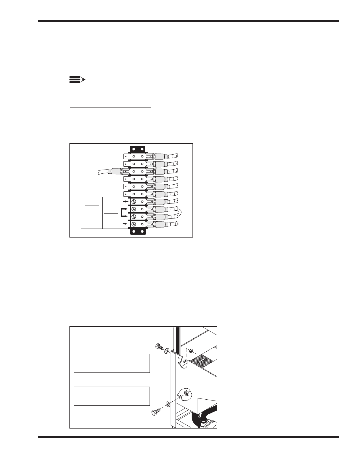
1. Labeled chemical signal connection points are provided inside the control cabinet for
chemical dispensing equipment (supplied by others).
Signal connection points include:
• Detergent signal 120VAC
between Wire #10 and Wire #2
(1 AMP MAX AMP LOAD)
• Rinse Aid/Sanitizer signal 120VAC
between Wire #15 and Wire #2
(1 AMP MAX AMP LOAD)
Figure 3
D-HB, D-H1, D-LF
Chemical Connection Points
Left Side Interior of Control Cabinet
Detergent
Refer to Figure 4.
1. Two removable black plugs, located on the rear and left side of the wash tank are
provided as detergent equipment insertion points.
Figure 4
D-HB, D-H1, D-LF
Wash Tank Detergent Equipment
Insertion Points
1/2" Black Removable Plug
Detergent Sensor Point
1/2" Black Removable Plug
Detergent Injection Point
5
6
CAUTION
120V SUPPLY
DISPENSERS
ONLY
RINSE/SANI
COMMON
RETURN
DETERGENT
12
17
18
19
15
2
2
10
8
INSTALLATION
Chemical Connections (cont’d)
Detergent (cont’d)
2. Detergent may be added manually if dishwasher is not equipped with dispensing
equipment. Consult your chemical supplier for recommended amounts.
Rinse Aid/Sanitizer
Model D-HB and D-H1
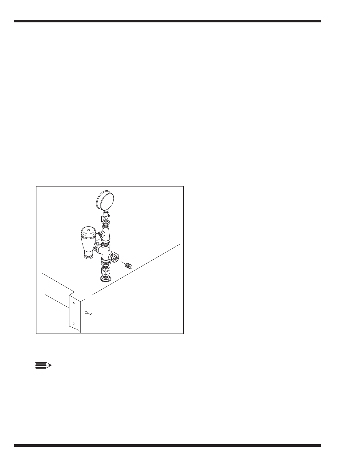
Refer to Figure 5.
1. A rinse aid injection point is provided via a 1/4" NPT plug located in the final rinse
piping. The plug is located in a cross fitting on the outlet side of the vacuum breaker.
The vacuum breaker is located behind the control cabinet at the top of the machine.
2. Use a liquid rinse aid.
Figure 5
Rinse Aid Injection Point
D-HB, D-H1 Only
NOTE:
Models D-HB and D-H1 do not require sanitizer.
9
INSTALLATION
Chemical Connections (cont’d)
Rinse Aid/Sanitizer (cont’d)
Model D-LF
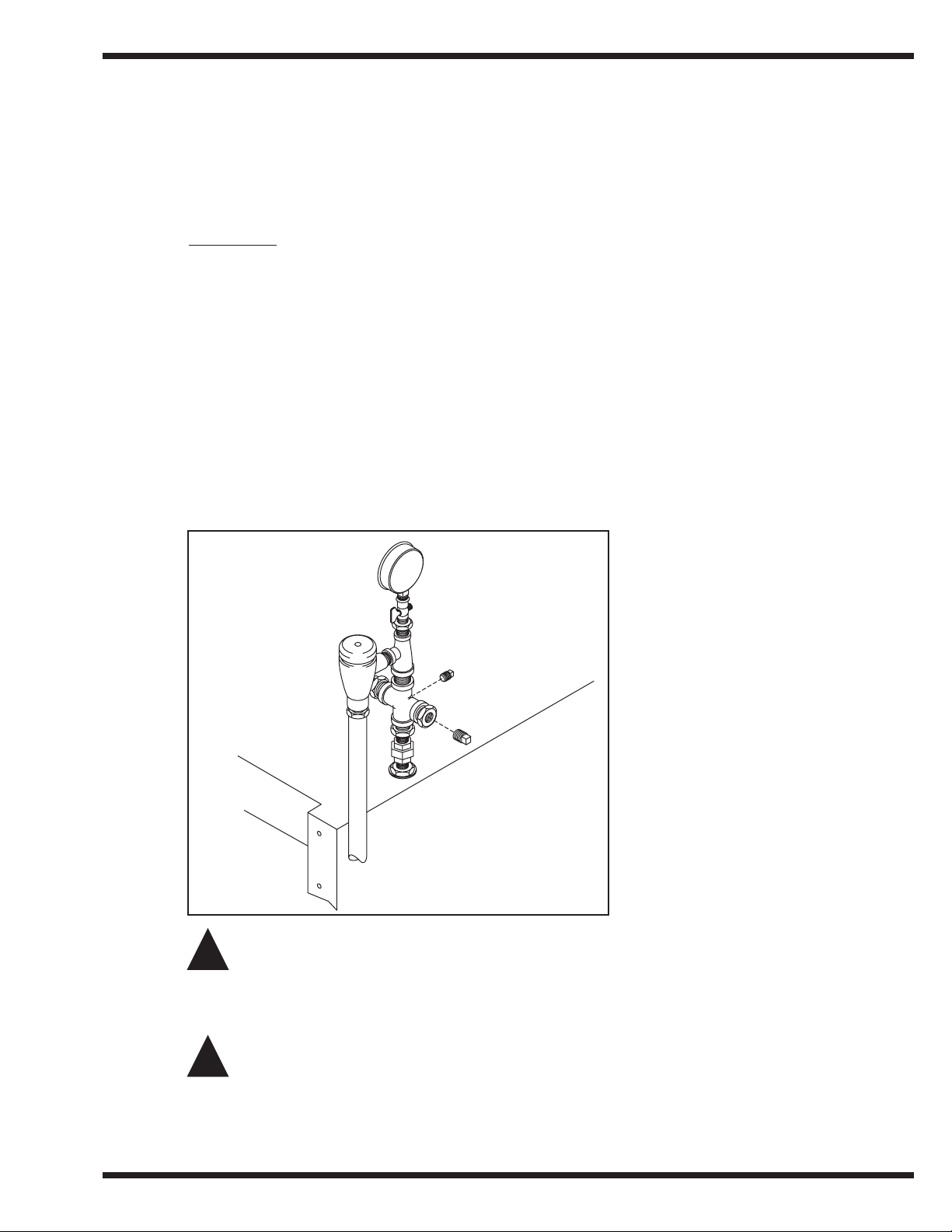
Refer to Figure 6.
1. A rinse aid injection point is provided via a 1/4" NPT plug located in the final rinse
piping. The plug is located in a cross fitting on the outlet side of the vacuum breaker.
The vacuum breaker is located behind the control cabinet at the top of the machine.
2. Use a liquid rinse aid.
3. A sanitizer injection point is provided via a 1/8" NPT plug located in the final rinse
piping. The plug is located in a cross fitting on the outlet side of the vacuum breaker.
The vacuum breaker is located behind the control cabinet at the top of the machine.
4. Use a sodium hypochlorite (Chlorine) based sanitizer at a minimum concentration of
50PPM in the final rinse. Use chlorine test papers to verify and monitor the 50PPM
chlorine level.
Figure 6
D-LF
Rinse Aid/Sanitizer Injection Points
WARNING:
Never premix rinse aid with the sanitizing agent. Mixing may cause hazardous gases
to form.
CAUTION:
Some metal, including silver, aluminum, and pewter are attacked by sodium
hypochlorite (chlorine sanitizer). Avoid cleaning these metals in a D-LF dishwasher.
!
!
INITIAL START-UP
After plumbing and electrical connections are completed, follow the steps below to place your
machine in service.
Model D-HB, D-H1 and D-LF
Refer to Figures 7 and 8 below.
1. Remove any foreign material from inside the machine. Make sure scrap screens are in
place.
2. Make sure wash and rinse arms are installed correctly.
3. Close the Door.
4. Turn the water and main power sources to the dishwasher ON.
5. Flip the Power switch to the ON position. The “power on” light will illuminate and the
machine will automatically fill with water.
6. Check the machine for leaks.
7. Push the Green Start Button to check automatic cycle.
8. Check pump motor rotation. Rotation is CW when viewed from rear of motor.
9. If machine checks okay, flip the power switch to OFF and machine will drain for
ten minutes.
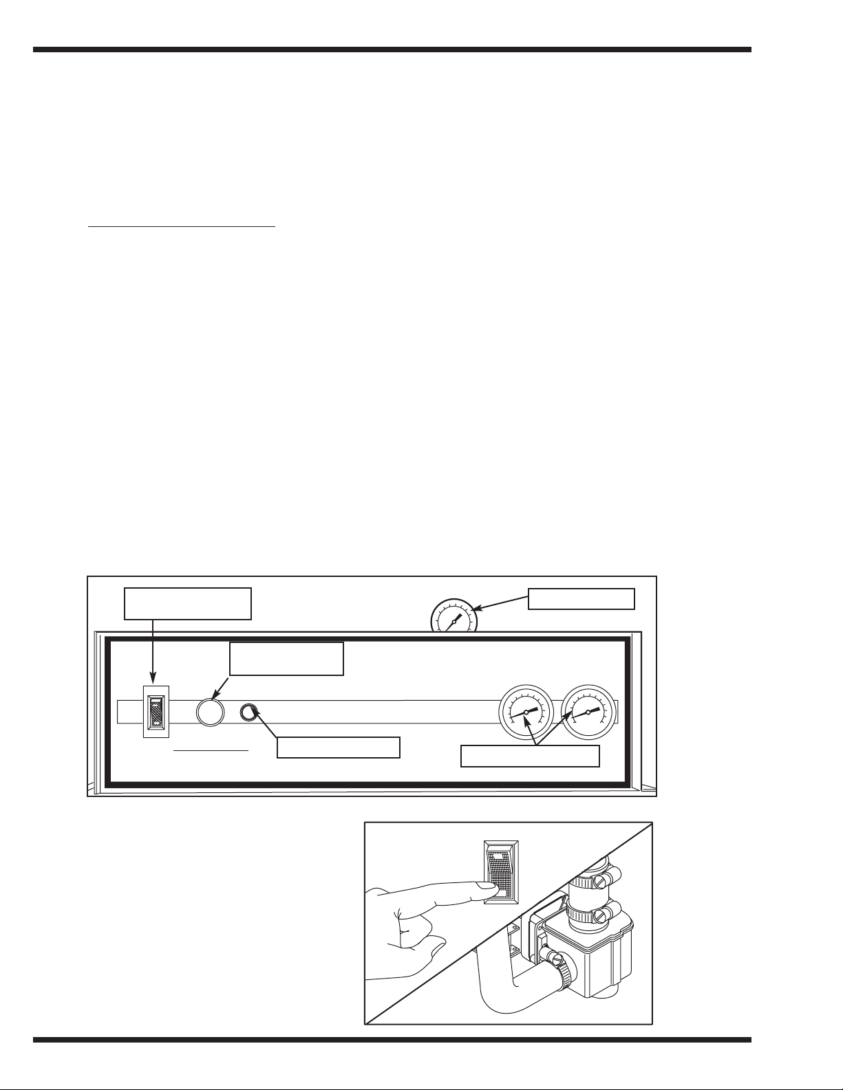
Figure 7
Operator Controls
Top Mounted Control Cabinet
Figure 8
Drain Assembly
10
INITIAL START-UP
Main power switch
circuit breaker
Green pushbutton
start switch
Green in cycle lite
Pressure gauge
Temperature Gauges
POWER
ON
OFF
START
WAR NING!
TURN OFF POWER BEFORE
SERVICING MACHINE
CYCLE
IN
Champion
POWER
ON
WASH RINSE
OFF

11
OPERATION
OPERATION
Model D-HB, D-H1 and D-LF
1. Close the door and flip power switch ON Power light illuminates. Drain valve closes.
Tank fills automatically and tank heat
comes on.
2. Monitor wash tank temperature gauge Wait for temperature reading to reach
Min. 150°F/66°C (D-HB, D-H1 Only)
Temperature reading must be
Min. 120°F-140°F/49°C-60°C Optimum
(For D-LF Only)
3. Prescrap and load ware into rack Place dishes edgewise in peg rack, cups and
bowls upside down in flat rack, and
silverware spread evenly in single layer in
flat rack.
4. Open door, insert rack
5. Close door, Push Green start button Green cycle light will illuminate. Automatic
cycle begins.
Machine washes for 45 sec., then pauses for
1 sec.
6. During Final Rinse monitor pressure Machine final rinses for 14 sec. Pressure
gauge and final rinse temperature gauge
reading must read between 20 – 22 PSI.
Temperature gauge must read
180 – 195°F/82 – 91°C (D-HB, D-H1 Only)
Min. 120° – 140°F/49°C – 60°C Optimum
(D-LF Only)
7. 60-second cycle complete Green cycle light goes out.
8. Open door, remove clean rack Insert another rack of soiled ware.
9. After each meal period or every two Turn power switch to OFF position and
hours operation machine will drain for ten minutes. Flush
interior and clean scrap screens and pump
intake strainer. Check spray arms and clean
if necessary. Flip power switch ON and OFF
to drain remaining water repeat as necessary.
NOTE:
Opening the door at any time during the cycle will stop the machine.
Closing the door and pushing the Green start button will resume the cycle where it
left off.

12
MAINTENANCE
MAINTENANCE
Cleaning your machine is the best maintenance that you can provide. Components that are not
regularly flushed and cleaned do not perform well.
The Maintenance intervals shown in the following schedules are the minimum requirements
necessary for the proper performance of your machine. Maintenance intervals should be
shortened whenever your machine is faced with abnormal working conditions, hard water, or
multiple shift operations.
Maintenance Schedule
CLEANING
• Every 2 Hours or After Each Meal Period
Model D-HB, D-H1, and D-LF
1. Flip the power switch OFF.
2. Machine drain valve will open for 10 minutes automatically.
3. Flush tank interior with fresh water.
4. Remove and clean the scrap screens. Clean the pump intake screen.
5. Inspect the spray arm nozzles and rinse nozzles. Clean if necessary.
6. Close door, flip power switch ON to refill machine.
• Every 8 Hours or at the End of the Day
Model D-HB, D-H1, and D-LF
1. Flip the power switch OFF.
2. Machine drain valve will open for 10 minutes automatically.
3. Flush tank interior with fresh water.
4. Remove and clean the scrap screens. Clean the pump intake screen.
5. Remove the spray arms.
6. Clean and inspect the spray arm bearings.
7. Flush the wash arm and rinse arm assemblies and nozzles.
8. Back flush the scrap screens and pump intake strainer.
9. Flip power switch ON then OFF to open drain valve for 10 minutes.
10. Reassemble the machine. Leave the door open to aid overnight drying.
CAUTION:
DO NOT LEAVE WATER IN WASH TANK OVERNIGHT
!

13
MAINTENANCE
DELIMING
Your dishwasher should be delimed regularly depending on the mineral content of your water.
Inspect the machine interior for mineral deposits and use a deliming solution for the best
cleaning results.
NOTE:
Consult your chemical supplier for an appropriate deliming solution.
WARNING:
Deliming solutions or other acids must not come in contact with household bleach
(sodium hypochlorite) or any chemicals containing chlorine, iodine, bromine, or
fluorine. Mixing will cause hazardous gases to form.
Skin contact with deliming solutions can cause severe irritation and possible chemical
burns. Consult your chemical supplier for specific safety precautions.
DELIMING PROCESS
Model D-HB, D-H1, and D-LF
1. Remove all dishes from machine.
2. Remove any chemical pick-up tubes from their containers.
3. Place each tube in a container of fresh water and prime the chemical lines for several
minutes to thoroughly flush chemical from the lines. Leave pick-up tubes out of their
containers.
4. Turn power switch to OFF position to drain machine for ten minutes, return power
switch to ON position to refill with fresh water.
5. Spray interior walls with delimimg solution and let sit for 5 or 10 minutes depending on
amount of build-up. Add deliming solution to wash tank. Do not let chemicals sit for
longer than 15 minutes.
6. Push the Green start button and run an automatic cycle.
7. Repeat Steps 3-4 if necessary.
8. Repeat Step 4.
9. Refill the machine and run a complete cycle two additional times. Drain and refill the
machine after each cycle to thoroughly flush any deliming solution from the interior of
the machine.
10. Flip the power switch to OFF.
11. Machine drain valve will open for 10 minutes to drain machine completely.
12. Deliming is complete.
!

14
MAINTENANCE
OPERATION CHECKS
• Daily
1. Check temperature gauges for proper readings.
2. Check pressure gauge for proper reading (D-H1, D-HB ONLY).
3. Check for leaks.
4. Check chemical supplies and refill as necessary.
• Weekly
1. Inspect all water lines for leaks.
2. Clean all detergent residue from the exterior of the machine.
3. Check the drains for leaks.
4. Clean accumulated mineral deposits from the tank heating elements
5. Check that float switch moves freely.
TROUBLESHOOTING
Before determining any specific cause of a breakdown or abnormal operation on your
dishwasher, check that:
Checklist
1. Main power and water supply are turned on to the machine
2. All switches are ON
3. Wash pipe and rinse nozzles are clean
4. Scrap screen(s) are properly positioned
5. Spray pipes are in their proper positions
6. Doors are fully closed
7. Thermostat(s) are at their correct setting
8. Sanitizer, detergent, and rinse additive dispensers are adequately filled.
9. Drain valve/timer problems see Appendix D for trouble shooting.
If a problem still exists, use the following for troubleshooting.

15
TROUBLESHOOTING
CONDITION CAUSE SOLUTION
Machine will not start Door not closed . . . . . . . . . . . . . . . . . Make sure doors are fully closed
Door safety switch faulty . . . . . . . . . . Contact your service agency
Start switch faulty . . . . . . . . . . . . . . . Contact your service agency
Main switch OFF . . . . . . . . . . . . . . . . Check disconnect
Overload protector tripped . . . . . . . . . Reset overload in control box
Low or no water Main water supply is turned off . . . . . Turn on house water supply
Faulty drain valve . . . . . . . . . . . . . . . . Contact your service agency
Machine doors not fully closed . . . . . Close doors securely
Faulty fill valve . . . . . . . . . . . . . . . . . Contact your service agency
Defective circuit board . . . . . . . . . . . . Contact your service agency
Stuck or defective float . . . . . . . . . . . Check floats and clean
Clogged “Y” strainer . . . . . . . . . . . . . Clean or replace
Continuous water filling Stuck or defective float . . . . . . . . . . . Check floats and clean
Drain valve will not close . . . . . . . . . Replace drain valve/Contact your service agency
Fill valve will not close . . . . . . . . . . . Clean or replace
Defective circuit board . . . . . . . . . . . . Contact your service agency
Any motor not running Overload protector tripped . . . . . . . . . Reset overload in control box
Defective motor . . . . . . . . . . . . . . . . . Contact your service agency
Wash tank water Incoming water temperature
temperature is low at machine too low . . . . . . . . . . . . . . Raise temperature to:
when in use . . . . . . . . . . . . . . . . . . . . . . . . . . . . . . 140°F/60°C for D-HB and D-LF,
. . . . . . . . . . . . . . . . . . . . . . . . . . . . . . 180°F/82°C for D-H1
Defective thermometer . . . . . . . . . . . . Check or replace
Defective thermostat . . . . . . . . . . . . . Check for proper setting or replace
Lime scale buildup
on heating elements . . . . . . . . . . . . . Delime element
Defective heater element . . . . . . . . . . Check or replace
Low steam pressure . . . . . . . . . . . . . . Check steam supply pressure (15 – 30 psi)
Defective steam trap . . . . . . . . . . . . . . Check or replace
Defective solenoid valve . . . . . . . . . . Check or replace
Insufficient pumped Clogged pump intake screen . . . . . . . Clean
spray pressure Clogged spray pipe . . . . . . . . . . . . . . . Clean
Scrap screen full . . . . . . . . . . . . . . . . . Must be kept clean and in place
Low water level in tank . . . . . . . . . . . Check drain
Pump motor rotation incorrect . . . . . . Reverse connection between L1 and L2
. . . . . . . . . . . . . . . . . . . . . . . . . . . . . . in Control Cabinet (3PH machines only)
Defective pump seal . . . . . . . . . . . . . . Contact Service Agent
Insufficient final rinse or Faulty pressure reducing valve . . . . . Clean or replace
no final rinse Improper setting on pressure
reducing valve . . . . . . . . . . . . . . . . . Set psi flow pressure at 20 – 22 psi/138 Kpa
Clogged rinse nozzle and/or pipe . . . . Clean
Improper water line size . . . . . . . . . . . Have installer change to proper size (3/4" min.)
Clogged “Y” strainer . . . . . . . . . . . . . Clean or replace
Low final rinse temperature Low incoming water temperature . . . Check house supply water temperature
Improper setting of booster
thermostat . . . . . . . . . . . . . . . . . . . . . Be sure booster thermostat is set to maintain
. . . . . . . . . . . . . . . . . . . . . . . . . . . . . . 180°F/82°C temperature
Defective booster thermostat . . . . . . . Replace thermostat
Defective thermometer . . . . . . . . . . . . Check for proper setting or replace
Poor washing results Detergent dispenser not
operating properly . . . . . . . . . . . . . . Contact detergent supplier
Insufficient detergents . . . . . . . . . . . . Contact detergent supplier
Wash water temperature
too low . . . . . . . . . . . . . . . . . . . . . . . See condition “Wash tank water temperature”
. . . . . . . . . . . . . . . . . . . . . . . . . . . . . . above.
Wash arm clogged . . . . . . . . . . . . . . . Clean
Improperly scraped dishes . . . . . . . . . Check scraping procedures
Ware being improperly placed
in rack . . . . . . . . . . . . . . . . . . . . . . . . Use proper racks. Do not overload racks
Improperly cleaned equipment . . . . . . Unclog wash sprays and rinse nozzles to
. . . . . . . . . . . . . . . . . . . . . . . . . . . . . . maintain proper pressure and flow conditions.
. . . . . . . . . . . . . . . . . . . . . . . . . . . . . . . Keep wash water as clean as possible.
Electric Elements or steam
coils has soil/lime buildup . . . . . . . . Clean and/or delime
Poor drying results Insufficient rinse-aid . . . . . . . . . . . . . Contact chemical supplier
Low final rinse temp . . . . . . . . . . . . . See condition “Low final rinse temperature”
. . . . . . . . . . . . . . . . . . . . . . . . . . . . . . above.
 Loading...