

Page 1
1/2 hp Chain Drive
Garage Door Opener
Models
• PD612EV
• HD420EV
FOR RESIDENTIAL USE ONLY
■ Please read this manual and the enclosed safety materials carefully!
■ Fasten the manual near the garage door after installation.
■ The door WILL NOT CLOSE unless the Protector System
properly aligned.
■ Periodic checks of the garage door opener are required to ensure safe operation.
■ The model number label is located on the left side panel of your garage
door opener.
■ This garage door opener is compatible with MyQ
■ Only enable the Timer-to-Close* or MyQ
door opener is installed on a sectional door. (*Not available on all models)
Write down the following information
for future reference:
®
®
remote operation feature* when the garage
®
is connected and
and Security✚ 2.0™ accessories.
CONTENTS
Preparation .............................. 1-4
Assembly ................................. 5-9
Installation ............................ 10-19
Install the Door Control .............20-21
Install the Protector System® ...... 22-25
Power .................................. 26-27
Adjustments .......................... 28-30
Operation.................................. 31
Features ................................... 32
Door Control ..........................33-34
Remote Control ...................... 34-35
To Erase the Memory .................... 35
To Open the Door Manually ............36
Maintenance .............................. 37
Troubleshooting ...................... 38-39
Accessories ............................... 40
Warranty .................................. 41
Repair Parts .......................... 42-43
.
.
Model Number:
Serial Number:
Date of Purchase:
www.chamberlain.com
The Chamberlain Group, Inc.
845 Larch Avenue
Elmhurst, Illinois 60126-1196
Page 2
Torsion
Spring
Extension
Spring
OR
Preparation
Safety Symbol and Signal Word Review
Thisgarage door opener has been designed and tested to offer safe service provided it is installed,
operated, maintained and tested in strictaccordance with the instructions and warnings contained in this
manual.
When you see these SafetySymbols and Signal Words on the following pages, they will alert you to the
possibilityof serious injuryor death if you do not complywith the warnings thataccompany them. The
hazard may come from something mechanical or from electric shock.Read the warnings carefully.
Mechanical
Electrical
When you see thisSignal Word on the following pages, it will alert you to the possibilityof damage to
your garage door and/or the garage door opener ifyou do not complywith the cautionary statementsthat
accompanyit.Read them carefully.
Check the Door
To prevent possible SERIOUSINJURYorDEATH:
• ALWAYS call a trained door systemstechnician if garage door binds,sticks,or is out of balance.
An unbalanced garage door may NOT reverse when required.
• NEVER tryto loosen, move or adjustgarage door, door springs, cables, pulleys,bracketsor their
hardware, ALLof which are under EXTREMEtension.
• Disable ALLlocksand remove ALLropes connected to garage door BEFORE installation and
operating garage door opener to avoid entanglement.
To prevent damage to garage door and opener:
• ALWAYS disable locksBEFORE installing and operating the opener.
• ONLY operate garage door opener at120 V, 60 Hz to avoid malfunction and damage.
1. Disable locksand remove any ropes connected to the garage door.
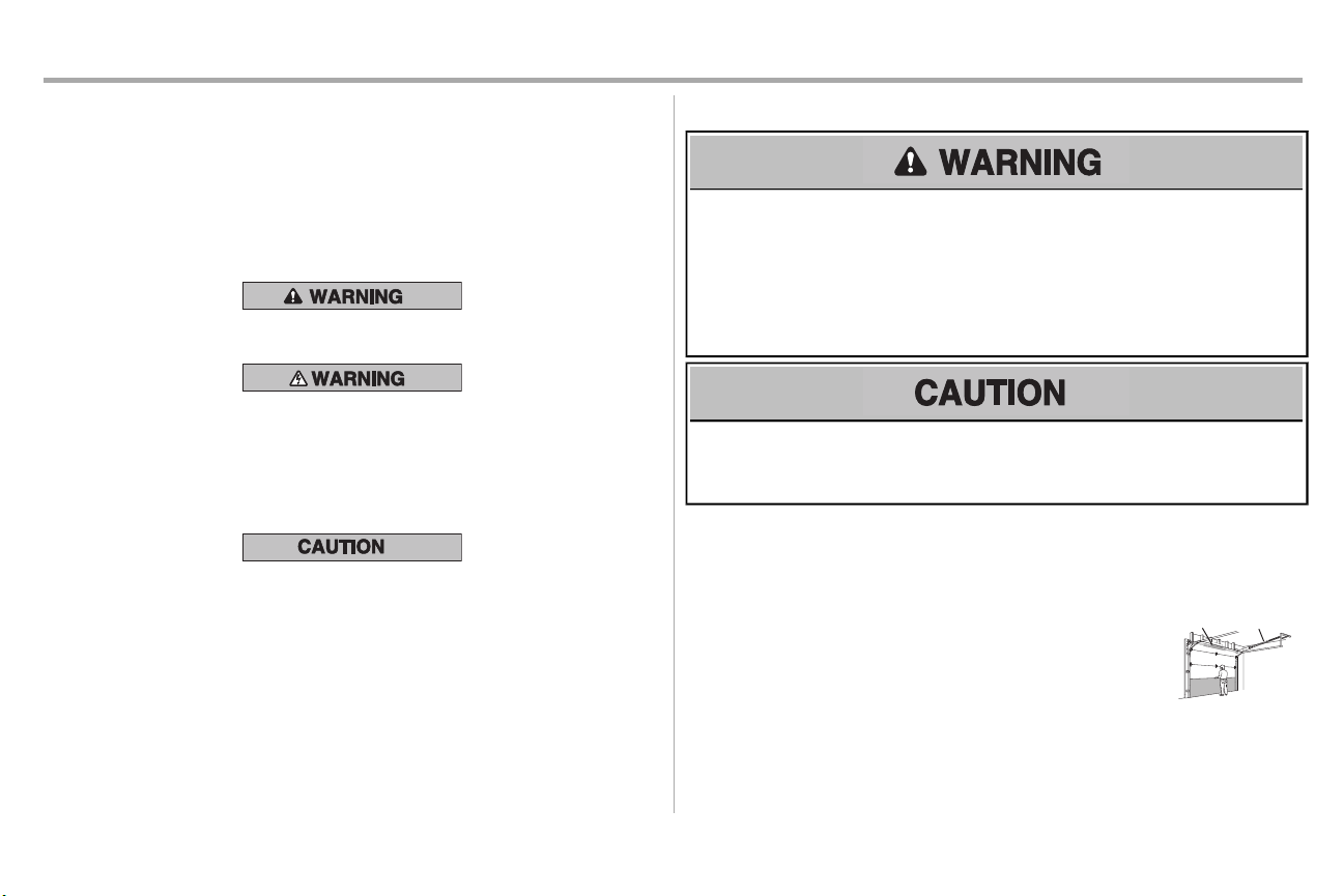
2. Liftthe door halfwayup. Release the door. Ifbalanced,it should
stayin place, supported entirely by itssprings.
3. Raise and lower the door to check for binding or sticking.Ifyour
door binds,sticks,or is out of balance, call a trained door systems
technician.
4. Checkthe seal on the bottom of the door.Any gap between the
floor and the bottom of the door mustnot exceed 1/4 inch (6 mm).
Otherwise,the safetyreversal systemmay not work properly.
5. The opener should be installed above the center of the door. If
there is a torsion spring or center bearing plate in the way of the
header bracket,it may be installed within 4 feet (1.2 m) to the left or
right of the door center. See page 13.
1
Page 3
2
1
3/16
7/16
1/2
5/32
5/16
5/8
9/16
1/4
7/16
Preparation
Additional Items You May Need:
Survey your garage area to see if you will need any of the following items:
n
(2) 2X4 PIECES OF WOOD
Maybe used to fasten the header bracketto the structural supports.Also used to position the
garage door opener during installation and for testing the safetyreversing sensors.
n
SUPPORT BRACKETANDFASTENING HARDWARE
Mustbe used if you have a finished ceiling in your garage.
n
EXTENSION BRACKETS (MODEL 41A5281) OR WOOD BLOCKS
Depending upon garage construction, extensionbracketsor wood blocksmay be needed to
install the safetyreversing sensor.
n
FASTENING HARDWARE
Alternate floor mounting of the safetyreversing sensor will require hardware not provided.
n
OUTSIDEQUICKRELEASE (MODEL 7702CB)
Required for a garage with NO access door.
n
DOOR REINFORCEMENT
Required if you have a lightweightsteel,aluminum, fiberglass or glass panel door.
n
RAIL EXTENSIONKIT
Required if your garage door is more than 7 feet (2.13 m) high.
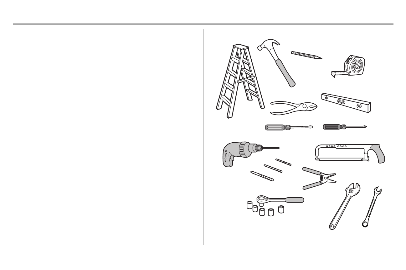
Tools Needed
2
Page 4
N
A
B
C
H
K
J
O
I
D
E
F
G
L
M
P
Preparation
Carton Inventory
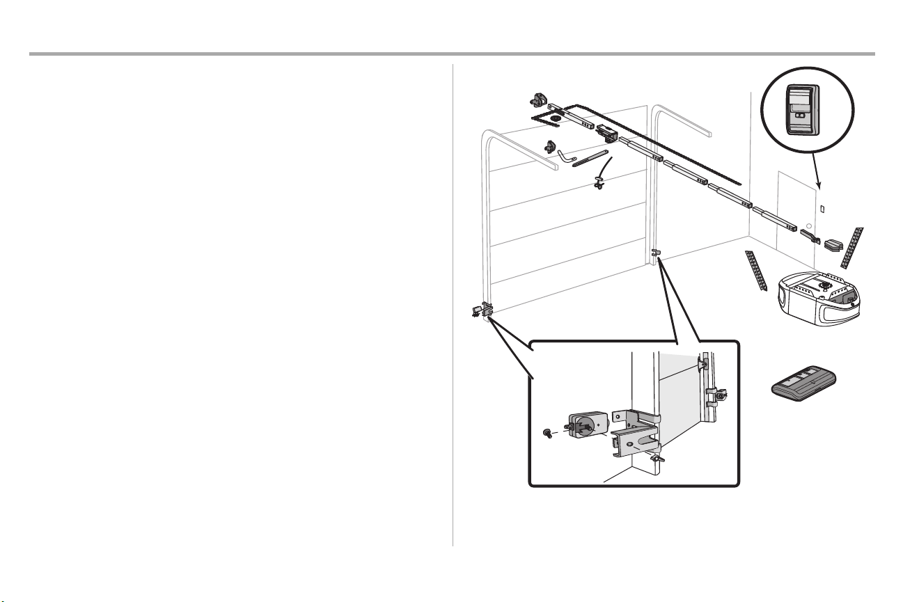
Your garage door opener is packaged in one carton which contains the motor unit and all parts
illustrated below.Accessoriesvary depending on the garage door opener model purchased.Depending
on your model, other accessories may be included with your garage door opener. Instructions for these
accessories will be attached to the accessoryand are notincluded in this manual. Ifanything is missing,
carefullycheck the packing material. Hardware for assemblyand installation is shown on the next page.
Save the carton and packing material until the installation and adjustment is complete.The images
throughout this manual are for reference only and your productmay look different.
A. Header bracket
B. Pulley
C. Door bracket
D. Curved door arm
E. Straight door arm (Packagedinside front rail section)
F. Trolley
NOTE: Be sure to assemble the trolley before sliding onto rail.
G. Emergency release rope and handle
H. Rail (1 front and 4 center sections)
I. Hanging brackets (2) (Packaged inside the front rail section)
J. Garagedoor opener (motor unit)
K. Chain spreader with screws
L. “U” bracket
M. Chain and cable
N. Door control
O. Remote control
P. The Protector System
Safetyreversing sensors with 2 conductor white and white/black wire attached: Sending Sensor (1),
Receiving Sensor (1), andSafety Sensor Brackets (2)
NOTSHOWN
White and red/white wire
Owner's manual
®
3
Page 5
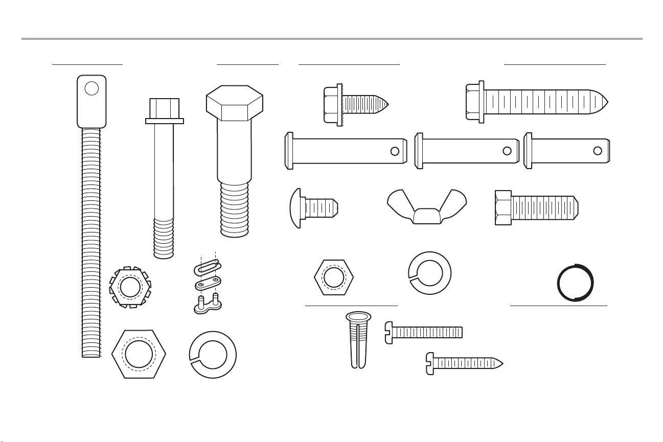
Bolt
1/4"-20x1-3/4"
Lock Nut
1/4"-20
Bolt
Nut 3/8" Lock Washer 3/8"
Master Link
Clevis Pin 5/16"x1-1/2"
Ring Fastener (3)
Hex Bolt 5/16"-18x7/8" (4)
Lock Washer
5/16"-18 (5)
Nut
5/16"-18 (6)
Self-Threading Screw
1/4"-14x5/8" (2)
Clevis Pin 5/16"x1"
Clevis Pin 5/16"x1-1/4"
Carriage Bolt
1/4"-20x1/2" (2)
Wing Nut 1/4"-20 (2)
ASSEMBLY HARDWARE INSTALLATION HARDWARE
Screw 6ABx1" (2)
Drywall Anchors (2)
Screw 6-32x1" (2)
DOOR CONTROL HARDWARE
Insulated
Staples
(N
ot Shown)
Lag Screw 5/16"-9x1-5/8" (4)
Threaded
Shaft
Preparation
Hardware Inventory
4
Page 6
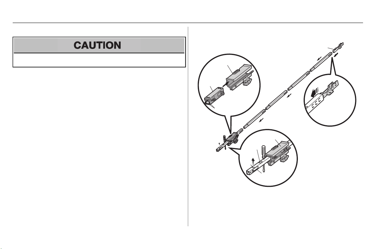
Assembly
To garage
door opener
(TO MOTOR UNIT)
Front Rail
Section
(TO DOOR)
“U” Bracket
Outer Trolley
Inner Trolley
Wear Pads
Rail
Tab
Trolley
Window
Cut-Out
SLIDE TO STOPS
ON TOP AND
SIDES OF
“U” BRACKET
Idler
Pulley
Hole
STEP 1 Assemble the rail and trolley
To prevent INJURY from pinching, keep hands and fingers away from the jointswhile assembling the
rail.
To avoid installation difficulties, do not run the garage dooropeneruntilinstructed to do so.
The frontrail hasa cut out “window” atthe door end (see illustration). The hole above thiswindow is
larger on the top of the rail than on the bottom.A smaller hole 3-1/2"(8.9 cm) awayis close to the rail
edge. Rotatethe back rail so it has a similar hole close to the opposite edge, about 4-3/4" (12 cm) from
the far end.
1. Removethe straight door arm and hanging bracketpackaged inside the front rail and set
aside for Installation Step 5 and 9. NOTE: To prevent INJURY while unpacking the rail
carefully remove the straight door arm stored within the rail section.
2. Align the rail sectionson a flat surfaceas shown and slide the tapered endsinto the larger
ones. Tabs along the side will lock into place.
3. Place the motor unit on packing material to protectthe cover,and restthe back end of the rail
on top. For convenience, put a support under the front end of the rail.
4. As a temporary stop,insert a screwdriver into the hole 10" (25 cm) from the front end ofthe rail,
as shown.
5. Checkto be sure there are 4plastic wear pads inside the inner trolley. Ifthey became loose
during shipping, check all packing material. Snap them back into position as shown.
6. Slide the trolley assemblytoward the screwdriveras shown.
7. Slide the rail onto the “U” bracket,until it reaches all the stopson the top and sides of the “U”
bracket.
5
Page 7
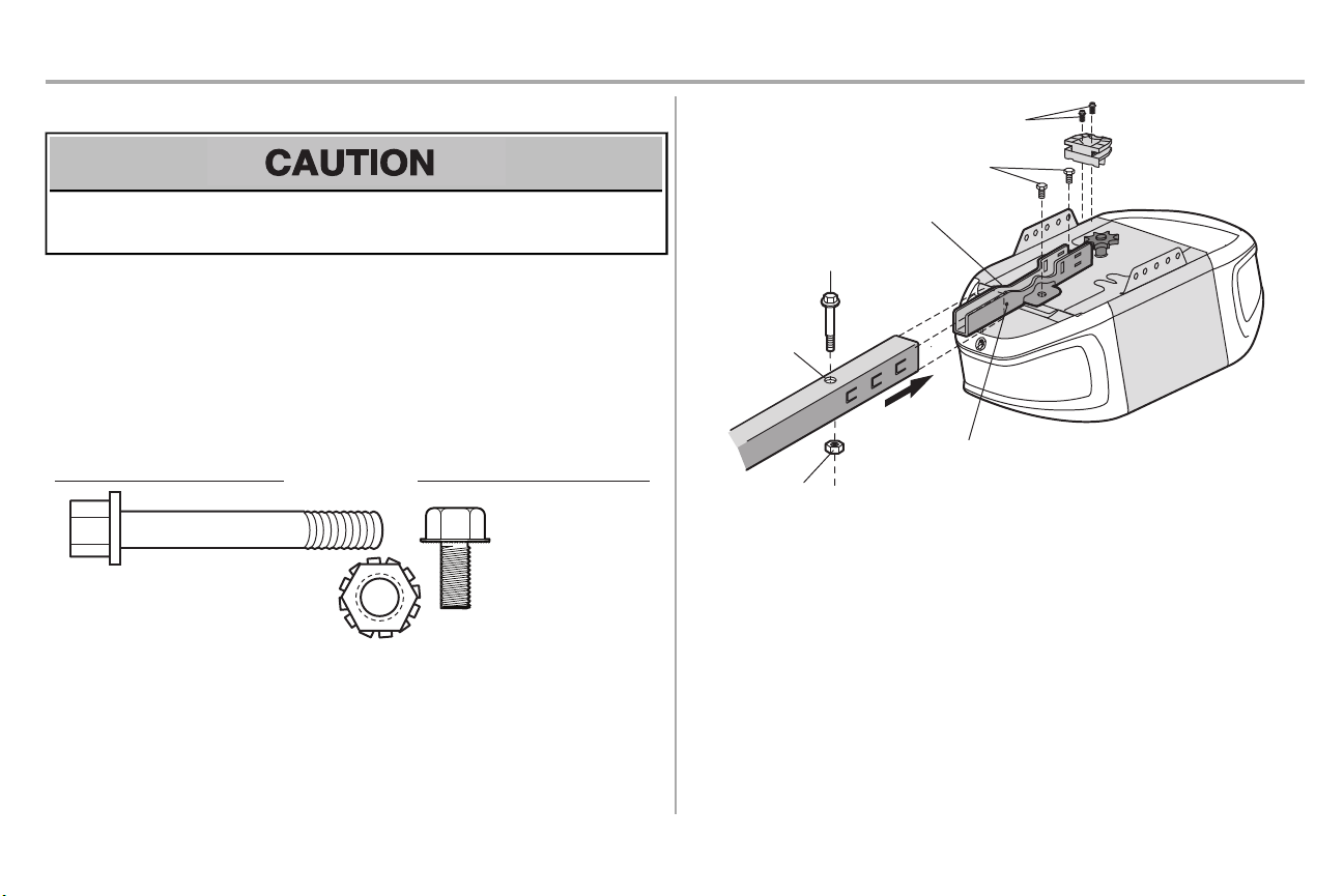
Assembly
(Mounted in the
Bolts
garage door
opener)
HARDWARE
Bolt 1/4"-20x1-3/4"
Lock Nut 1/4"-20
“U” Bracket
Bolts
Hex Screws
8-32x7/16
SLIDE RAIL TO
STOPS ON TOP AND
SIDES
Cover
Protection
Bolt Hole
Bolt 1/4"-20x1-3/4"
Lock Nut 1/4"-20
STEP 2 Fasten the rail to the motor unit
To avoid SERIOUS damage to garage door opener, use ONLY those bolts/fasteners mounted in the
top of the opener.
1. Inserta 1/4"-20x1-3/4" bolt into the cover protection bolt hole onthe back end of the rail as
shown.Tighten securely with a 1/4"-20 lock nut.Do NOT overtighten.
2. Removethe bolts fromthe top of the motor unit.
3. Usethe carton to support the front end of the rail.
4. Place the “U” bracket,flat side down onto the motor unit and align the bracketholes with the
bolt holes.
5. Fasten the “U” bracket with the previously removed bolts;DO NOT use any power tools. The
use of power toolsmay permanently damage the garage door opener.
6. Attach spreader to the motor unit with twoscrews.
6
Page 8
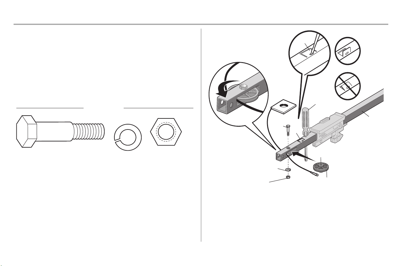
Assembly
HARDWARE
Bolt
Nut 3/8"
Lock Washer 3/8"
Screwdriver
Rail
Idler Pulley
Grease Inside Pulley
Bolt
Lock Washer 3/8"
Nut 3/8"
Rail
Tab
CORRECT
INCORRECT
Rail Tab
STEP 3 Install the idler pulley
1. Lay the chain/cable beside the rail, as shown. Grasp the end with the cable loop and pass
approximately 12" (30 cm) ofcable through the window.Allow it to hang until AssemblyStep 4.
2. Removethe tape from the idler pulley.The inside center should be pre-greased. Ifdry,
regrease to ensure proper operation.
3. Place the idler pulley into the window as shown.
4. Insertthe idler bolt from the top through the rail and pulley. Tighten with a 3/8" lock washer and
nut underneath the rail until the lockwasher is compressed.
5. Rotatethe pulley to be sure it spins freely.
6. Locate the rail tab. The rail tab is between the idler bolt and the trolley in the front rail section.
Usea flat head screwdriver and lift the rail tab until the tab is vertical (90º).
7
Page 9
Assembly
HARDWARE
Ma
ster
Link
Threaded Shaft
Chain Link
c.
Threaded
Shaft
Outer
Nut
Front Rail
Section
(TO DOOR)
Inner
Nut
Lock
Washer
Master
Link
Master
Link
b.
a.
Sprocket
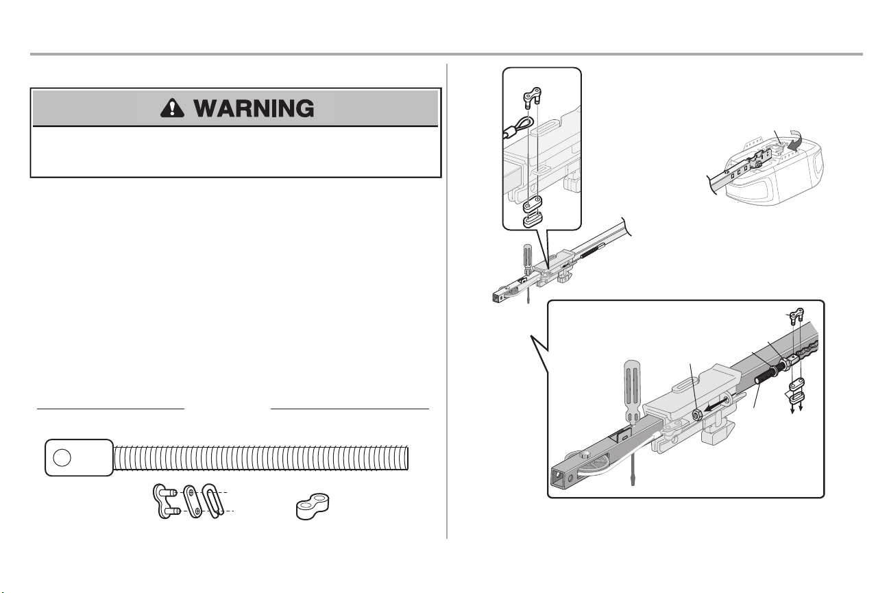
STEP 4 Install the chain
To avoid possible SERIOUS INJURY to fingers from moving garage door opener:
• ALWAYS keep hand clear of sprocketwhile operating opener.
• Securely attach chain spreader BEFORE operating.
1. Pull the cable around the idler pulley and toward the trolley.
2. Connectthe cable to the retaining slot on the trolley. (a)
a. Push pins of master link bar through cable link and trolley slot.
b. Push masterlink cap over pins and pastpin notches.
c. Slide clip-on spring over cap and onto pin notchesuntil both pins are securely
locked in place.
3. Withthe trolley against the screwdriver, dispense the remainder of the cable/chain along the
rail toward the motor unit into the slot on the chain spreader, around the sprocketonto the
chain spreader and continuing to the trolley assembly and continuing to the trolley assembly.
The sprocketteethmust engage the chain. (b)
4. Thread the inner nut and lock washer onto the trolley threaded shaft.
5. Insertthe trolley threaded shaftthrough the hole in the trolley. Be sure the chain is not
twisted.(c)
6. Loosely thread the outer nut onto the trolley threaded shaft.
7. Removethe screwdriver.
8
Page 10
Assembly
Outer
Nut
Lock
Washer
Trolley
Threaded
Shaft
Inner Nut
To Tighten
Inner Nut
To Tighten Outer Nut
Base of Rail
Mid length of Rail
Chain
1/4" (6 mm)
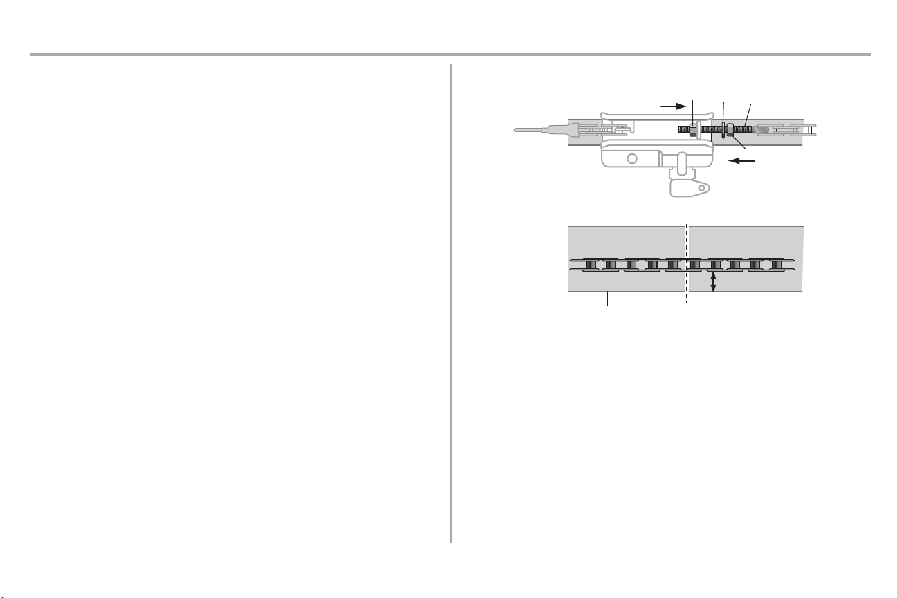
STEP 5 Tighten the chain
1. Spin the inner nut and lock washer down the trolley threaded shaft,awayfrom the trolley.
2. To tighten the chain, turn the outer nut in the direction shown.
3. When the chain is approximately 1/4" (6 mm) above the base of the rail at it's midpoint,retighten the inner nut to secure the adjustment.
Sprocketnoise can result if the chain is too loose.
When installation is complete, you may notice some chain droop with the door closed. Thisis normal. If
the chain returns to the position shown when the door is open, do not re-adjustthe chain.
NOTES:During future maintenance, ALWAYS pull the emergency release handle to disconnect the
trolley before adjusting the chain.
You may notice loosening of the chain after AdjustmentStep 3 (Test the Safety Reversal System). Check
for proper tension and readjustchain if necessary.Then repeat Adjustment Step 3.
You have now finished assemblingyourgarage dooropener.Please read the followingwarnings
beforeproceeding to the installationsection.
9
Page 11
Installation
IMPORTANT INSTALLATION INSTRUCTIONS
To reduce the risk of SEVERE INJURY or DEATH:
1. READ ANDFOLLOW ALL INSTALLATIONWARNINGS AND INSTRUCTIONS.
2. Install garage door opener ONLY on properly balanced and lubricated garage door. An
improperly balanced door may NOTreverse when required and could result in SEVERE
INJURYor DEATH.
3. ALL repairs to cables, spring assembliesand other hardware MUSTbe made by a trained
door systems technician BEFORE installing opener.
4. Disable ALL locksand remove ALL ropes connected to garage door BEFORE installing
opener to avoid entanglement.
5. Install garage door opener 7 feet (2.13 m) or more above floor.
6. Mount the emergencyrelease within reach,but at least 6 feet (1.83 m) above the floor and
avoiding contactwith vehicles to avoid accidental release.
7. NEVER connectgarage door opener to power source until instructed to do so.
8. NEVERwearwatches,rings or loose clothing while installing or servicing opener. They could
be caught in garage door or opener mechanisms.
9. Install wall-mounted garage door control:
• within sight of the garage door.
• out of reach of children at minimumheight of 5 feet (1.5 m).
• away from ALL moving partsof the door.
10. Placeentrapment warning label on wall next to garage door control.
11. Placemanual release/safetyreverse testlabel inplain view on inside of garage door.
12. Upon completion of installation,testsafetyreversal system.Door MUST reverse on contact
witha 1-1/2" (3.8 cm) high object(or a2x4 laid flat) on the floor.
13. To avoid SERIOUS PERSONAL INJURY or DEATH from electrocution,disconnectALL
electricpower BEFORE performing any serviceor maintenance.
14. DO NOT enable the Timer-to-Close functionality if operating either one-piece or swinging
garage doors. To be enabled ONLY when operating a sectional door.
10
Page 12
Installation
Header Wall
Vertical Centerline of Garage Door
2x4
Structural
Supports
Level
(Optional)
Unfinished
Ceiling
2x4
OPTIONAL CEILING MOUNT
FOR HEADER BRACKET
Sectional door with curved track
Header Wall
Track
2" (5 cm)
Highest Point
of Travel
Door
One-piece door with horizontal track
Header Wall
Track
2" (5 cm)
Highest
Point
of Travel
Door
One-piece door without track:
jamb hardware
Header Wall
8" (20 cm)
Highest
Point of
Travel
Door
Jamb
Hardware
One-piece door without track:
pivot hardware
Header Wall
8" (20 cm)
Highest
Point of
Travel
Door
Pivot
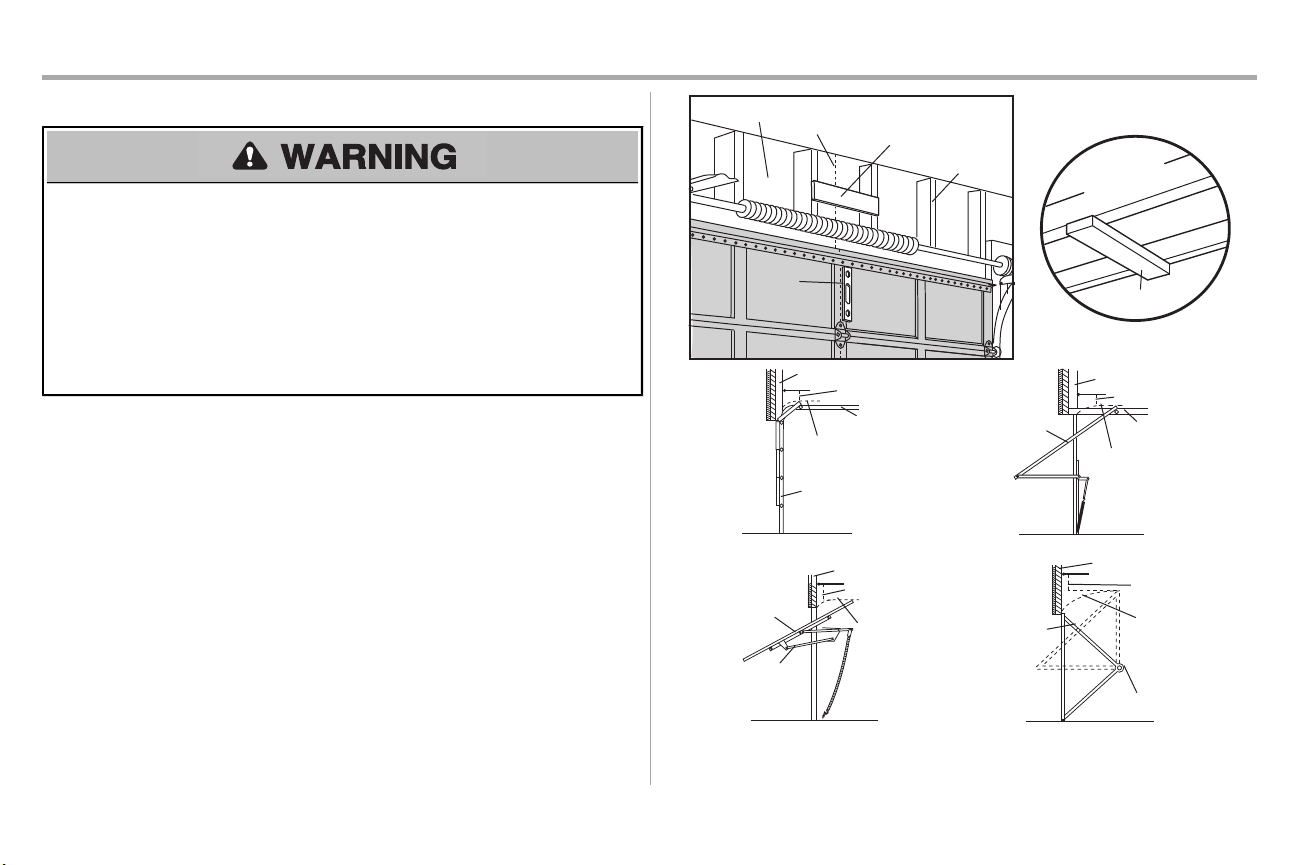
STEP 1 Determine the header bracket location
To prevent possible SERIOUSINJURY or DEATH:
• Header bracket MUST be RIGIDLY fastened to structural support on header wall or ceiling,
otherwise garage door might NOT reverse when required. DO NOTinstall header bracket over
drywall.
• Concreteanchors MUST be used if mounting header bracketor 2x4 into masonry.
• NEVER tryto loosen, move or adjustgarage door, springs, cables,pulleys,brackets,or their
hardware, ALL of which are under EXTREME tension.
• ALWAYS call a trained door systemstechnician if garage door binds,sticks,or is out of balance.
An unbalanced garage door might NOT reverse when required.
Installation procedures vary according to garage door types.Follow the instructions which apply to your
door.
1. Close the door and mark the inside vertical centerline ofthe garage door.
2. Extend the line onto the header wall above the door.
You can fasten the header bracket within4 feet (1.22 m) of the left or right of the door
center only if a torsionspring or center bearingplate is in the way; or you can attach it to
the ceiling when clearance is minimal.(It may be mounted on the wall upside down if
necessary, to gain approximately 1/2" (1 cm).
Ifyou need to install the header bracket on a2x4 (on wall or ceiling), use lag screws(not
provided) to securely fasten the 2x4 to structural supports.
3. Open your door to the highest point of travel as shown.Draw an intersecting horizontal line on
the header wall 2" (5 cm) above the high point.
l
2" (5 cm) above the high point for sectional door and one-piece door with track.
l
8" (20 cm) above the high point for one-piece door without track.This height will provide travel
clearance for the top edge of the door. NOTE:If the total number of inches exceeds the height
available in your garage, use the maximumheight possible, or refer to page 12 for ceiling
installation.
11
Page 13
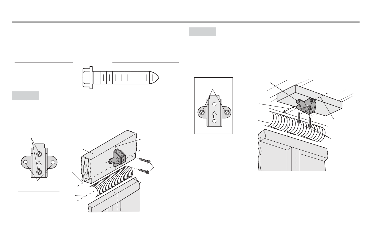
Installation
HARDWARE
Lag Screw 5/16"-9x1-5/8"
UP
Wall Mount
Optional Mounting
Holes
Vertical
Centerline of
Garage Door
(Header Wall)
Header
Bracket
2x4 Structural
Support
Door Spring
(Garage Door)
Highest Point
of Garage
Door Travel
Horizontal
Line
Lag Screw
5/16"-9x1-5/8"
UP
(Header Wall)
Ceiling Mounting
Holes
(Finished Ceiling)
Vertical
Centerline of
Garage
Door
Header
Bracket
6" (15 cm)
Maximum
Door Spring
(Garage Door)
Lag Screw
5/16"-9x1-5/8"
STEP 2 Install the header bracket
You can attach the header bracket either to the wall above the garage door, or to the ceiling. Follow the
instructions which will work best for your particular requirements.Do not installthe header bracket over
drywall. If installingintomasonry,use concrete anchors (not provided).
OPTION A WALL INSTALLATION
1. Centerthe bracket on the verticalcenterline with the bottomedge ofthe bracketon the
horizontal line as shown.
2. Mark the vertical set of bracketholes. Drill 3/16" pilot holes and fasten the bracketsecurely to a
structural support withthe hardware provided.
OPTION B CEILING INSTALLATION
1. Extend the vertical centerline onto the ceiling as shown.
2. Center the bracketon the vertical mark, no more than 6" (15 cm) from the wall. Make sure the
arrow is pointing away fromthe wall. The bracketcan be mounted flush against the ceiling
when clearance is minimal.
3. Mark the side holes.Drill 3/16" pilot holes and fastenbracket securely to a structural support
withthe hardware provided.
12
Page 14
Installation
HARDWARE
Clevis Pin 5/16"x1-1/2"
Ring Fastener
Clevis Pin
5/16"x1-1/2"
Ring Fastener
Connected Disconnected
One-piece
door
without
tracks
All other
door types
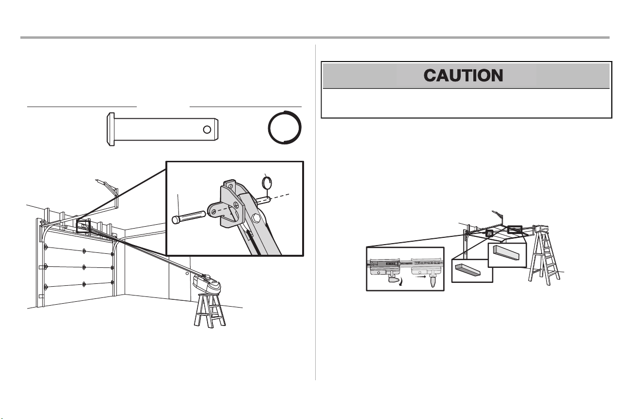
STEP3 Attach the rail to the header bracket
1. Align the rail with the header bracket. Insert the clevis pin through the holes in the header
bracketand rail. Secure with the ring fastener.
NOTE: Use the packing material as a protective base for the garage door opener.
STEP 4 Position the garage door opener
To prevent damage to garage door,rest garage door opener rail on 2x4 placed on top section of
door.
1. Removethe packing material and lift the garage door opener onto a ladder.
2. Fully open the door and place a 2x4 (laid flat) under the rail. For one-piece doors without
tracks,lay the 2x4 on it's side.
NOTE: A 2x4 is ideal for setting the distance between the rail and the door. Ifthe ladder is not tall
enough you will need help atthis point. Ifthe door hitsthe trolley when itis raised, pull the trolley release
arm down to disconnectthe inner and outer trolley. Slide the outer trolley toward the garage door
opener. The trolley can remain disconnected until instructed.
13
Page 15
Installation
Finished Ceiling
Unfinished Ceiling
HARDWARE
Hex Bolt 5/16"- 18x7/8"
Nut 5/16"-18
Lock Washer
5/16"-18
Lag Screw 5/16"-9x1-5/8"
Finished
Ceiling
(not provided)
Lag Screw
5/16"9x1-5/8"
1
2
3
(not
provided)
Hex Bolt
5/16"- 18x7/8"
Nut 5/16"-18
Lock Washer
5/16"-18
4
5
6
Lag Screw
5/16"9x1-5/8"
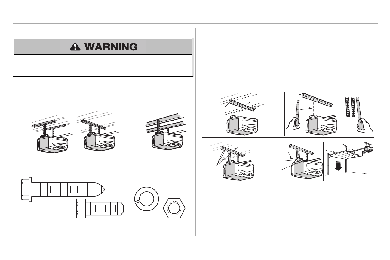
STEP 5 Hang the garage door opener
To avoid possible SERIOUS INJURY from a falling garage door opener, fasten it SECURELY to
structural supports of the garage. Concrete anchors MUST be used if installing ANY bracketsinto
masonry.
Hanging the garage door opener will vary depending on your garage. Below are three example
installations.Your installation may be different.For ALL installations the garage door opener MUSTbe
connected to structural supports.The instructions illustrate one of the examples below.
1. On finished ceilings, use the lag screwsto attach a support bracket (not provided) to the
structural supports before installing the garage door opener.
2. Make sure the garage door opener isaligned with the header bracket.Measure the distance
fromeach side of the garage door opener to the support bracket.
3. Cutboth pieces of the hanging bracket (not provided) to required lengths.
4. Attach the end of each hanging bracketto the supportbracketwithappropriate hardware (not
provided).
5. Attach the garage door opener to the hanging bracketswith the hex bolts,lockwashers,and
nuts.
6. Removethe 2x4 and manually closethe door. If the door hits the rail, raise the header bracket.
14
Page 16
Installation
or
or
NOTICE
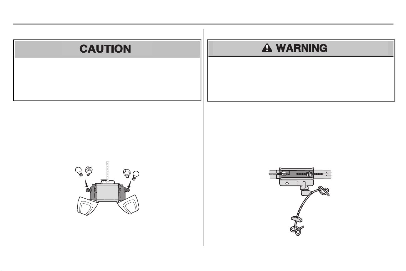
STEP 6 Install the light bulbs
To prevent possible OVERHEATING of the end panel or light socket:
• UseONLY A19 incandescent (100W maximum)or compact fluorescent (26W maximum)light
bulbs.
• DO NOTuse incandescent bulbs larger than 100W.
• DO NOTuse compactfluorescent light bulbs larger than 26W (100W) equivalent.
• DO NOTuse halogen bulbs.
• DO NOTuse short neck or specialtylight bulbs.
1. Pull on the top sides of the light lens and rotate the light lens down.
2. Insertan A19 incandescent (100W maximum)or compact fluorescent (26W, 100W equivalent)
light bulb into the light socket.
3. Rotatethe lens up to close.
NOTE: Do not use halogen, short neck,or specialty light bulbs as these may overheat the end panel or
light socket. Do not use LED bulbs as they may reduce the range or performance of your remote controls.
STEP 7 Attach the emergency release rope and handle
To prevent possible SERIOUSINJURY or DEATH from a falling garage door:
• Ifpossible, use emergencyrelease handle to disengage trolley ONLY when garage door is
CLOSED. Weak or broken springs or unbalanced door could resultin an open door falling rapidly
and/or unexpectedly.
• NEVER use emergency release handle unlessgarage doorway is clear of persons and
obstructions.
• NEVER use handle to pull door open or closed. Ifrope knot becomes untied, you could fall.
1. Insertone end of the emergency release rope through the handle. Make sure that “NOTICE” is
right side up. Tie a knot at least1 inch (2.5 cm) fromthe end ofthe emergency release rope.
2. Insertthe other end of the emergency release rope through the hole in the trolley release arm.
Mount the emergencyrelease within reach,but at least 6 feet (1.83 m) above floor, avoiding
contactwith vehicles to preventaccidental release and secure with a knot.
NOTE: Ifit is necessary to cut the emergency release rope, seal the cut end with a match or lighter to
prevent unraveling. Ensure the emergencyrelease rope and handle are above the top of all vehicles to
avoid entanglement.
15
Page 17
Installation
A horizontal and vertical reinforcementis needed for
li
ghtweight garage doors (fi
berglass, aluminum, steel,
doors with glass panel, etc.) (not provided).
A horizontal reinforcement brace should be long
enough to be secured to two or three vertical supports.
A vertical reinforcement brace should cover the height
of the top panel.
FIGURE 1
Self-Threading Screw
1/4"-14x5/8"
HARDWARE
FIGURE 2
FIGURE 4
FIGURE 5
FIGURE 3
Vertical
Reinforcement
Vertical Centerline
of Garage Door
UP
Door Bracket
Vertical Reinforcement
Vertical Centerline
of Garage Door
Bolt 5/16"-18x2"
(not provided)
Lock Washer 5/16"
Nut 5/16"-18
Door Bracket
UP
Vertical
Centerline
of Garage
Door
UP
Vertical Centerline of
Garage Door
Bolt 5/16"-18x2"
(not provided)
UP
Inside Edge of Door or
Reinforcement Board
Self-Threading Screw
1/4"-14x5/8"
Self-Threading
Screw
1/4"-14x5/8"
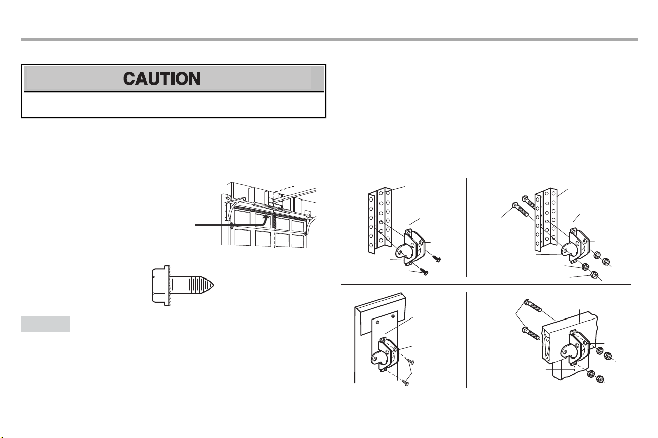
STEP 8 Install the door bracket
Fiberglass,aluminum or lightweightsteel garage doorsWILLREQUIRE reinforcementBEFORE
installation of door bracket.Contactyour door manufacturer for reinforcementkit.
Figure 1 shows one piece of angle iron as the horizontal brace. For the vertical brace, 2 pieces of angle
iron are used to create a U-shaped support. The bestsolution is to check with your garage door
manufacturer for an opener installationdoor reinforcement kit.
NOTE: Many door reinforcement kitsprovide for direct attachment of the clevis pin and door arm. In this
case you will not need the door bracket;proceed to the next step.
OPTION A SECTIONALDOORS
1. Center the door bracket on the previously marked vertical centerline used for the header
bracketinstallation. Note correctUP placement, as stamped inside the bracket.
2. Position the top edge of the bracket2"-4" (5-10 cm) below the top edge of the door, OR
3. Mark,drill holes and install as follows,depending onyour door’s construction:
directlybelow any structural support across the top of the door.
Metal or light weight doors using a vertical angle ironbrace between the door panel support
and the doorbracket:
• Drill 3/16" fastening holes.Secure the door bracket using the two selfthreading screws.
(Figure 2)
• Alternately,use two 5/16" bolts,lockwashers and nuts (not provided). (Figure 3)
Metal,insulated or light weight factory reinforced doors:
• Drill 3/16" fastening holes.Secure the door bracket using the self-threading screws.
(Figure 4)
Wood Doors:
• Usetop and bottomor side to side door bracketholes. Drill 5/16" holes through the door and
secure bracketwith 5/16"x2" carriage bolts,lockwashers and nuts (not provided). (Figure 5)
NOTE: The 1/4"-14x5/8" self-threading screws are notintended for use on wood doors.
16
Page 18
Installation
For a door with no exposed
framing, or for the optional
installation, use lag screws
5/16"x1-1/2" (not provided)
to fasten the door bracket.
Vertical
Centerline
of Garage
Door
Optional
Placement
of Door
Bracket
Door Bracket
Header Bracket
Header Wall
2x4 Support
(Finished Ceiling)
Door
Bracket
Top of Door
(Inside Garage)
Top Edge of
Door
Optional
Placement
Optional
Placement
Top Edge
of Door
Top of Door
(Inside Garage)
Door
Bracket
Carriage Bolt 5/16"x2"
(not provided)
Nut 5/16"-18
Lock Washer 5/16"
Metal Door
Wood Door
Self-Threading
Screw 1/4"-14x5/8"
STEP 8 Install the door bracket (continued)
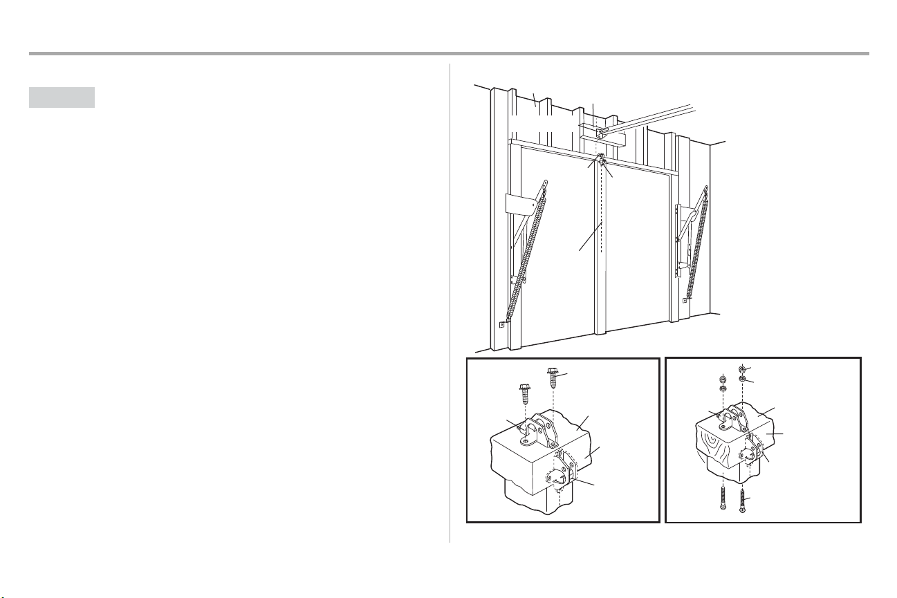
OPTION B ONE-PIECEDOORS
1. Center the door bracket on the top of the door, in line with the header bracket as shown.
2. Mark either the leftand right,or the top and bottomholes.
Metal Doors:
• Drill 3/16" pilot holes and fasten the bracketwith the self-threading screwsprovided.
Wood Doors:
• Drill 5/16" holes and use 5/16"x2" carriage bolts,lockwashers and nuts (not provided) or 5/16"x11/2" lag screws(not provided) depending onyour installation needs.
NOTE: The door bracketmay be installed on the top edge ofthe door if required for your installation.
(Refer to the dotted line optional placement drawing.)
17
Page 19
Installation
HARDWARE
Hex Bolt 5/16"-18x7/8"
Nut 5/16"-18
Lock
Washer
5/16"
-18
Clevis Pin 5/16"x1"
Clevis Pin 5/16"x1-1/4"
Ring Fastener
Straight
Door Arm
Curved
Door
Arm
(Groove
facing
out)
CORRECT
Straight
Door
Arm
Curved
Door
Arm
INCORRECT
Lock Washer
5/16" -18
Nut
5/16"-18
Hex Bolt 5/16"-18x7/8"
Clevis Pin 5/16"x1-1/4"
Ring Fastener
Clevis Pin
5/16"x1"
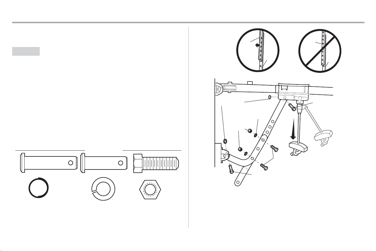
STEP 9 Connect the door arm to the trolley
Installation will vary according to the garage door type.Follow the instructions which apply to your door.
OPTION A SECTIONAL DOORS
IMPORTANT:The groove on the straight door arm MUST faceaway from the curved door arm.
1. Close the door. Disconnectthe trolley by pulling the emergencyrelease handle.
2. Attach the straight door arm to the outer trolley using the clevis pin. Secure with the ring
fastener.
3. Attach the curved door arm to the door bracketusing the clevispin. Secure with the ring
fastener.
4. Bring arm sections together. Find two pairs of holes that line up and join sections.Select holes
as far apart as possible to increase door arm rigidity and attach using the bolts,nuts,and lock
washers.
5. Pull the emergency release handle toward the garage door opener until the trolley release
arm is horizontal.The trolley will re-engage automaticallywhen the garage door opener is
activated.
NOTE: Ifthe holes in the curved door arm and the straight door arm do not align, reverse the straight
door arm, selecttwo holes (as far apart as possible) and attach using bolts , nuts,and lock washers . If the
straight door armis hanging down too far, you may cut 6 inches (15 cm) from the solid end.
18
Page 20
Installation
HARDWARE
Hex Bolt 5/16"-18x7/8"
Nut 5/16"-18
Lock
Washer
5/16"
-18
Clevis Pin 5/16"x1"
Clevis Pin 5/16"x1-1/4"
Ring Fastener
One-Piece Door without Track
One-Piece Door with Track
Straight
Door Arm
Curved
Door
Arm
(Groove
facing out)
CORRECT
INCORRECT
Straight
Door
Arm
Curved
Door
Arm
Ring
Fastener
Ring Fastener
Nut 5/16"-18
Nut 5/16"-18
Ring
Fastener
Ring Fastener
Lock Washer 5/16" -18
Lock Washer 5/16" -18
Clevis Pin 5/16"x1-1/4"
Clevis Pin
5/16"x1-1/4"
Hex Bolt 5/16"-18x7/8"
Hex Bolt 5/16"-18x7/8"
Clevis Pin
5/16"x1"
Clevis Pin
5/16"x1"
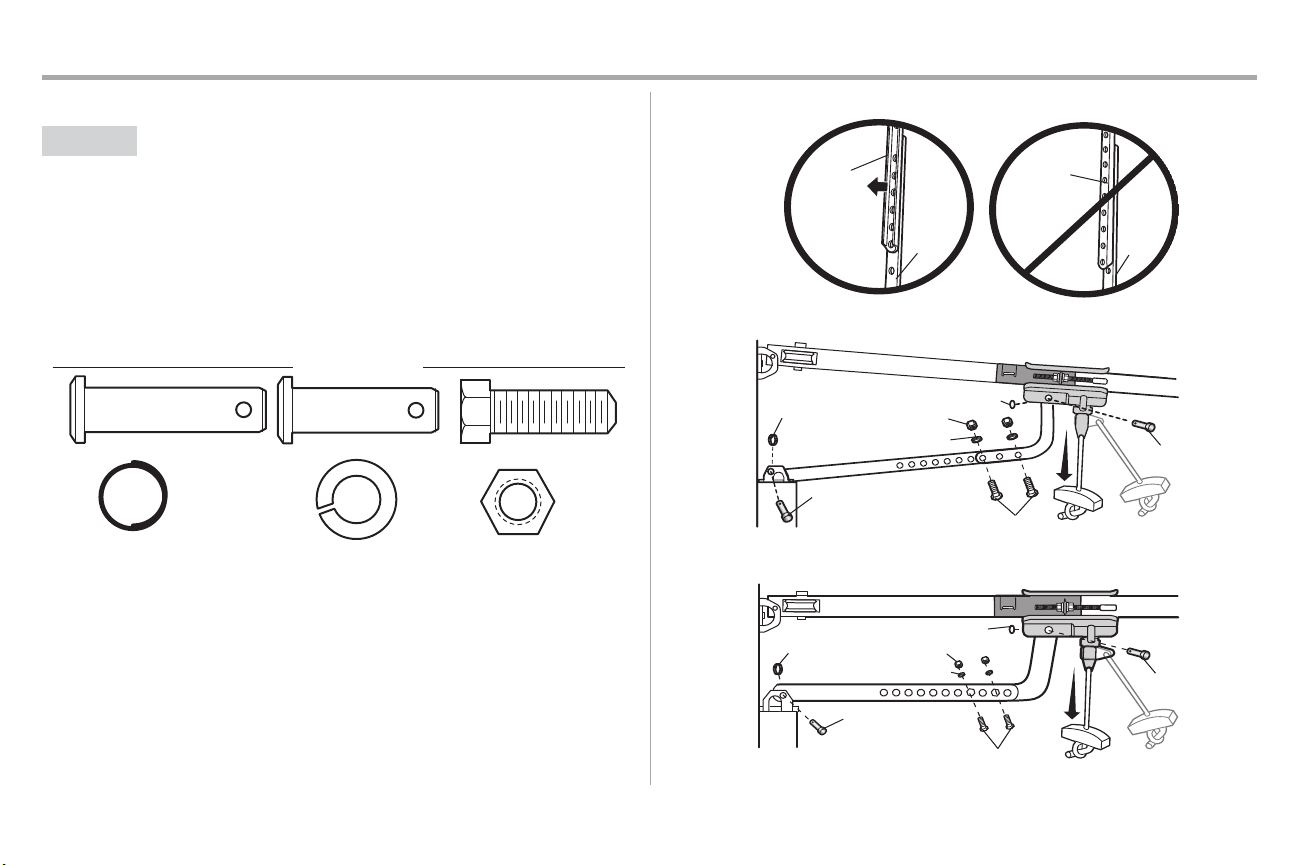
STEP 9 Connect the door arm to the trolley (continued)
OPTION B ONE-PIECE DOORS
IMPORTANT:The groove on the straight door arm MUST faceaway from the curved door arm.
1. Close the door. Disconnectthe trolley by pulling the emergencyrelease handle.
2. Fasten the straight door arm and the curved door armtogether to the longest possible length
3. Attach the straight door arm to the door bracket using the clevispin. Secure with the ring
4. Attach the curved door arm to the trolley using the clevispin. Secure with the ring fastener.
5. Pull the emergency release handle toward the garage door opener until the trolley release
(with a 2 or3 hole overlap) using the bolts,nuts,and lockwashers.
fastener.
arm is horizontal.
19
Page 21
Installation
HARDWARE
Screw
6ABx1"
(2)
Drywall
Anchors
(2)
Screw
6-32x1" (2)
7/16" (11 mm)
Wall
1
2 3
DRYWALL
GANG BOX
6ABx1"
6-32x1"
Drywall Anchor
4-5
6
6-32x1"
GANG BOX
8
DRYWALL
6ABx1"
Drywall Anchor
7
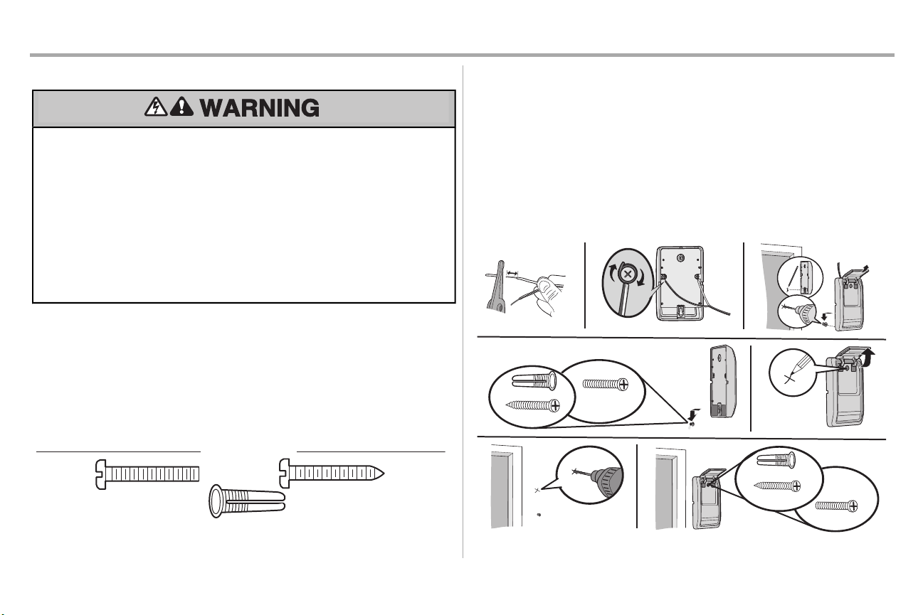
STEP10 Install the door control
To prevent possible SERIOUSINJURY or DEATH from electrocution:
• Be sure power is NOT connected BEFORE installing door control.
• ConnectONLY to 12 VOLT low voltage wires.
To prevent possible SERIOUSINJURY or DEATH from a closing garage door:
• Install door control within sight of garage door, out of reach of children at a minimum height of 5
feet(1.5 m), and away from ALL moving parts of door.
• NEVER permit children to operate or play with door control push buttons or remote control
transmitters.
• Activate door ONLY when itcan be seen clearly, is properly adjusted,and there are no
obstructions to door travel.
• ALWAYS keep garage door in sight until completelyclosed. NEVER permitanyone to cross path
of closing garage door.
INTRODUCTION
Compatible with MyQ®enabled accessories, see page 40. Your garage door opener is compatible with
up to 2 MyQ®door controls.NOTE: Older Chamberlain door controls and third party products are not
compatible.
Install the door control within sight of the door at a minimum height of 5 feet (1.5 m) where small children
cannot reach,and awayfrom the moving parts of the door. For gang box installations it is not necessary
to drill holes or installthe drywall anchors. Use the existingholes in the gang box.
NOTE: Your product may look different than the illustrations.
1. Strip 7/16 inch (11 mm) of insulation fromone end of the wire and separate the wires.
2. Connectone wire to each of the two screwson the back of the door control. The wires can be
connected to either screw.If your garage is pre-wired for the door control choose any two
wires to connect,note which wires are used so the correctwires are connected to the garage
door opener in a later step.
3. Mark the location of the bottommounting hole and drill a 5/32 inch (4 mm) hole.
4. Install the bottomscrew,allowing 1/8 inch (3 mm) to protrude from the wall.
5. Position the bottomhole ofthe door control over the screwand slide down into place.
6. Liftthe push bar up and mark the top hole.
7. Removethe door control from the wall and drill a 5/32 inch (4 mm) hole for the top screw.
8. Position the bottomhole ofthe door control over the screwand slide down into place. Attach
the top screw.
20
Page 22
Installation
HARDWARE
Ins
ulated
Staple
(Not Shown)
Staple
RED
WHITE
WHITE
GREY
7/16" (11 mm)
2
3
1
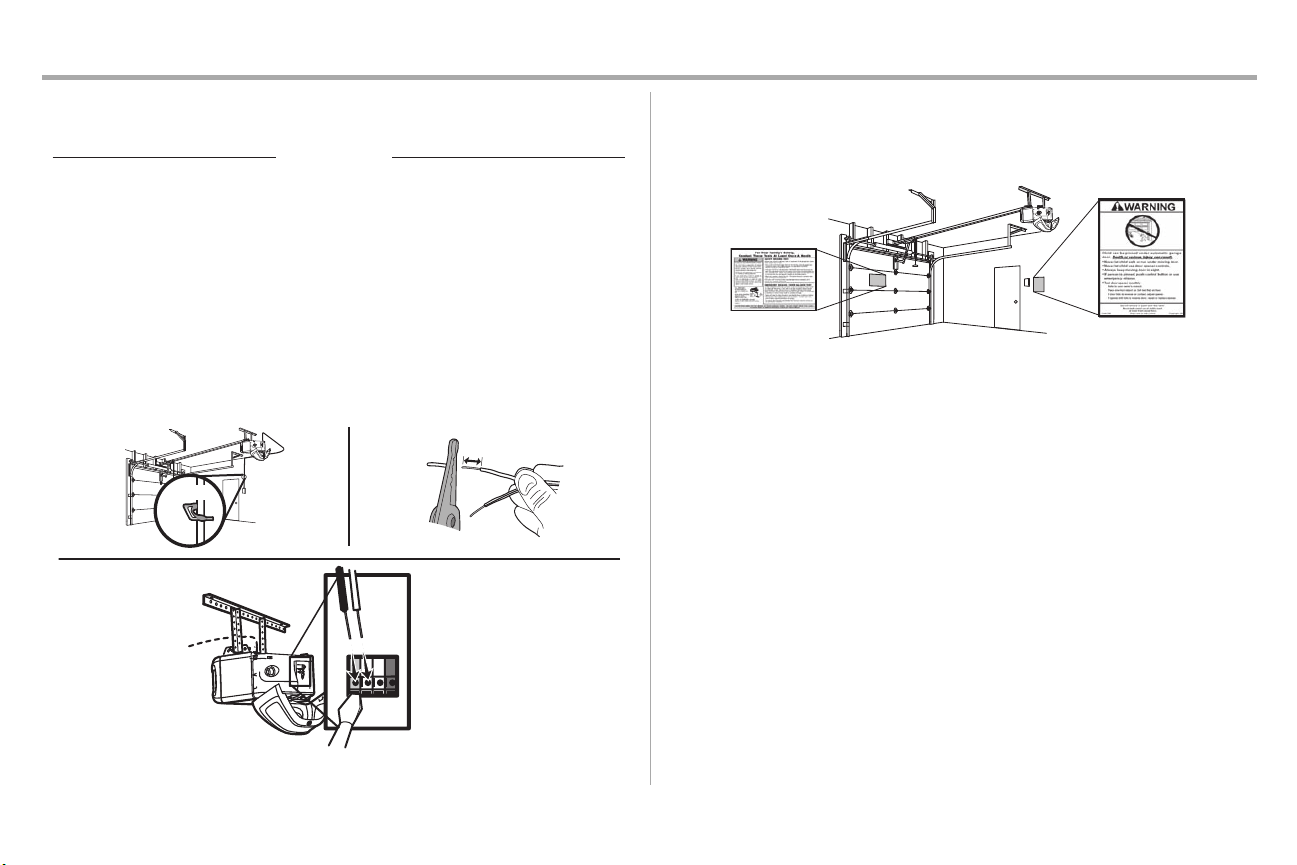
STEP 11 Wire the door control to the garage door opener
1. Run the whiteand red/white wire fromthe door control to the garage door opener. Attach the
wire to the wall and ceiling with the staple (not applicable for gang boxor pre-wired
installations).Do not pierce the wire withthe staple as thismay cause a short or an open
circuit.
2. Strip 7/16 inch (11 mm) of insulation fromthe end ofthe wire near the garage door opener.
3. Connectthe wire to the red and white terminalson the garage door opener. If your garage is
pre-wired make sure you use the same wires that are connected to the door control. To insert
or release wires from the terminal, push in the tab with screwdriver tip.
STEP 12 Attach the warning labels
1. Attach the entrapment warning label on the wall near the door control with tacks or staples.
2. Attach the manual release/safetyreverse testlabel in a visible location on the inside of the
garage door.
21
Page 23

Installation
Safety Reversing Sensor
6" (15 cm) max. above floor
Invisible Light Beam
Protection Area
HARDWARE
Carriage Bolt
1/4"-20x1/2"
Wing Nut
1/4"-20
No more
than 6 inches
(15 cm)
Carriage Bolt
1/4"-20x1/2"
Wing Nut
1/4"-20
1
2
3
STEP 13 Install the Protector System
®
Be sure power is NOT connected to the garage door opener BEFORE installing the safetyreversing
sensor.
To prevent SERIOUSINJURY or DEATH from closing garage door:
• Correctlyconnectand align the safetyreversing sensor. This required safetydevice MUST NOT be
disabled.
• Install the safetyreversing sensor so beam is NO HIGHERthan 6" (15 cm) above garage floor.
IMPORTANTINFORMATIONABOUTTHESAFETYREVERSINGSENSORS
The safety reversingsensors must be connected and aligned correctly before the garage door
openerwillmove in the down direction.
The sending sensor (with an amber LED) transmitsan invisible light beam to the receiving sensor (with a
green LED).If an obstructionbreaksthe light beam while the door is closing,the door will stop and
reverse to the full open position, and the garage door opener lightswill flash 10 times.
NOTE: For energy efficiencythe garage door opener will enter sleep mode when the door is fully
closed. The sleep mode shuts the garage door opener down until activated.The sleep mode is
sequenced with the garage door opener lightbulb; as the light bulb turns off the sensor LEDs will turn off
and whenever the garage door opener lights turn on the sensor LEDs will light.The garage door opener
will not go into the sleep mode until the garage door opener has completed 5 cyclesupon power up.
NOTE: Wheninstallingthe safety reversing sensors check the following:
l
Sensors are installed inside the garage, one on either side of the door.
l
Sensors are facing each other with the lensesaligned and receiving sensor lens does not
receive directsunlight.
l
Sensors are no more than 6 inches(15 cm) above the floor and the light beam is
unobstructed.
The safety reversing sensorscan be attached to the door track,the wall,or the floor. The sensors should
be no more than 6 inches (15 cm) above the floor. If the door trackwill not support the sensor bracketa
wall installation is recommended. Choose one of the following installations.
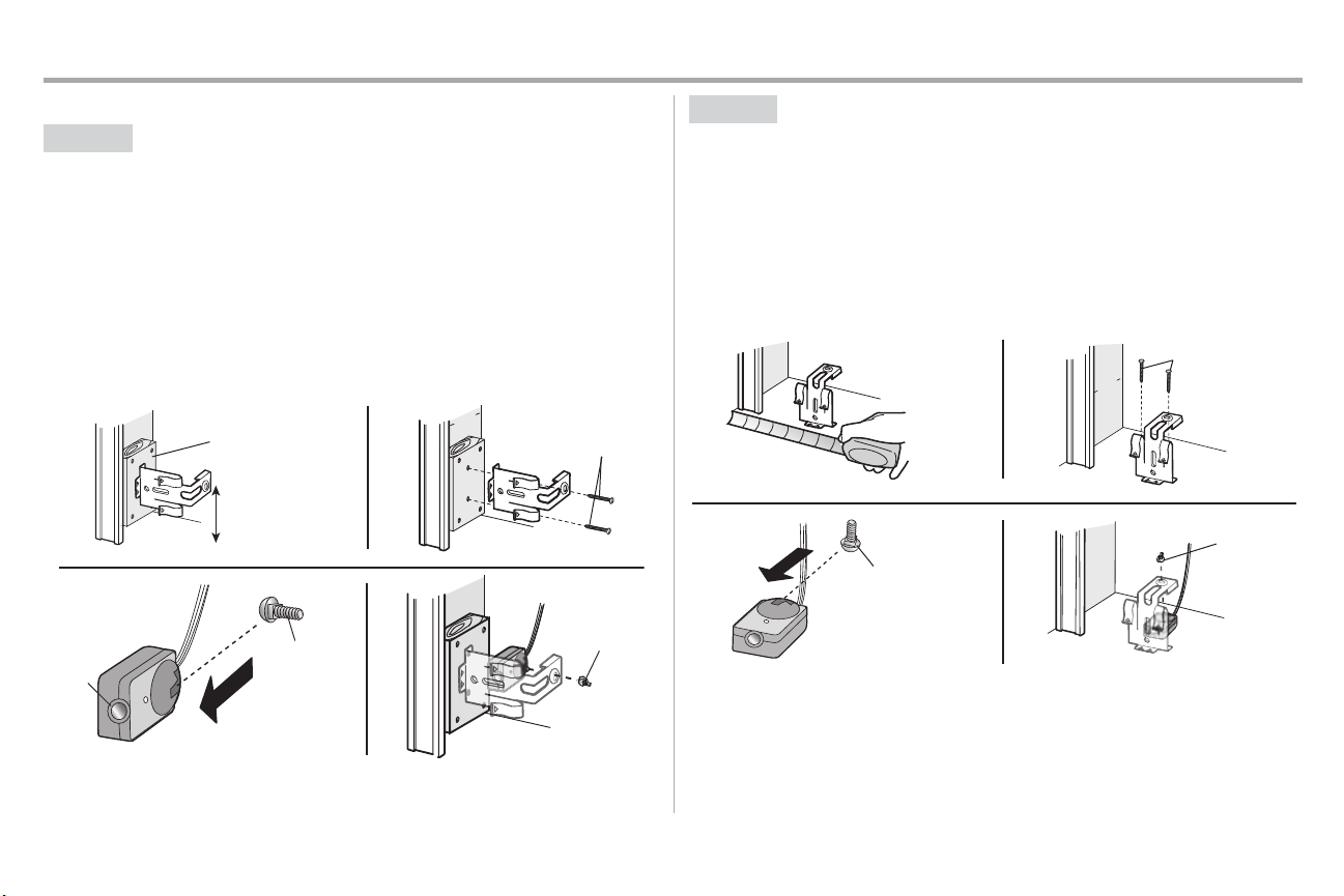
OPTION A DOORTRACKINSTALLATION
1. Slide the curved arms of the sensor bracket around the edge of the door track.Snap into place
so that the sensor bracketis flush against the track.
2. Slide the carriage boltinto the sloton each sensor.
3. Insertthe bolt through the hole in the sensor bracketand attach with the wing nut.The lenses
on both sensors should point toward each other. Make sure the lens is not obstructed by the
sensor bracket.
22
Page 24
Installation
(Not provided)
No more than
6 inches (15 cm)
1
2
Inside
G
arage
Wall
(Not provided)
Lens
Carriage Bolt
1/4"-20x1/2"
Wing Nut
1/4"-20
3
4
I
nsid
e
G
arage
Wa
l
l
(Not provided)
1 2
Carriage Bolt
1/4"-20x1/2"
Wing Nut
1/4"-20
3
4
STEP 13 Install the Protector System®(continued)
OPTION B WALLINSTALLATION
Ifadditional clearance is needed an extension bracket(not provided) orwood blockscan be used. Make
sure each brackethas the same amount of clearance so they will align correctly.
1. Position the sensor bracketagainst the wall with the curved arms facing the door. Make sure
there is enough clearance for the beam to be unobstructed.Mark holes.
2. Drill 3/16 inch pilot holes for each sensor bracketand attach the sensor bracketsto the wall
using lag screws(not provided).
3. Slide the carriage boltinto the sloton each sensor.
4. Insertthe bolt through the hole in the sensor bracketand attach with the wing nut.The lenses
on both sensors should point toward each other. Make sure the lens is not obstructed by the
sensor bracket.
OPTION C FLOORINSTALLATION
Usean extensionbracket (not provided) or wood blockto raise the sensor bracket if needed.
1. Carefullymeasure the position of both sensor bracketsso they will be the same distance from
the wall and unobstructed.
2. Attach the sensor bracketsto the floor using concreteanchors (not provided).
3. Slide the carriage boltinto the sloton each sensor.
4. Insertthe bolt through the hole in the sensor bracketand attach with the wing nut.The lenses
on both sensors should point toward each other. Make sure the lens is not obstructed by the
sensor bracket.
23
Page 25
Installation
HARDWARE
Ins
ulated
Staple
(Not Shown)
Staple
7/16" (11 mm)
WHITE
WHITE
GREY
RED
1
2
3
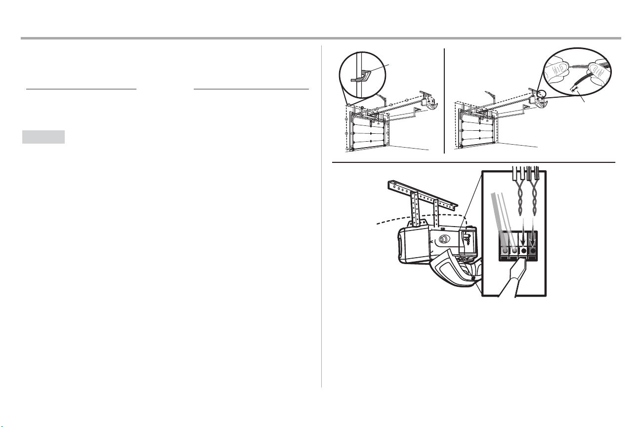
STEP 14 Wire the Safety Reversing Sensors
Ifyour garage already has wires installed for the safetyreversing sensors, proceed to page 25.
OPTION A
1. Run the wire fromboth sensors to the garage door opener. Attach the wire to the wall and
2. Strip 7/16 inch (11 mm) of insulation fromeach set of wires. Separate the wires. Twistthe white
3. Insertthe white wires into the white terminal on the garage door opener. Insertthe white/black
INSTALLATION WITHOUTPRE-WIRING
ceiling with the staples.
wires together. Twistthe white/blackwires together.
wires into the grey terminal on the garage door opener. To insert or remove the wires from the
terminal,push in the tab with a screwdriver tip.
24
Page 26
Installation
Safety reversing
sensor wires
Pre-installed
wires
White
White/Black
Yellow (for example)
Purple (for example)
Not Provided
Pre-installed wires
Safety reversing
sensor wires
7/16" (11 mm)
Yellow
Purple
1
3
4
7/16"
(11 mm)
2
WHITE
WHITE
RED
GREY
Purple
(for
example)
Yellow
(for example)
To insert or remove the wires from
the terminal, push in the tab with a
screwdriver tip.
5
STEP 14 Wire the Safety Reversing Sensors (continued)
OPTION B PRE-WIREDINSTALLATION
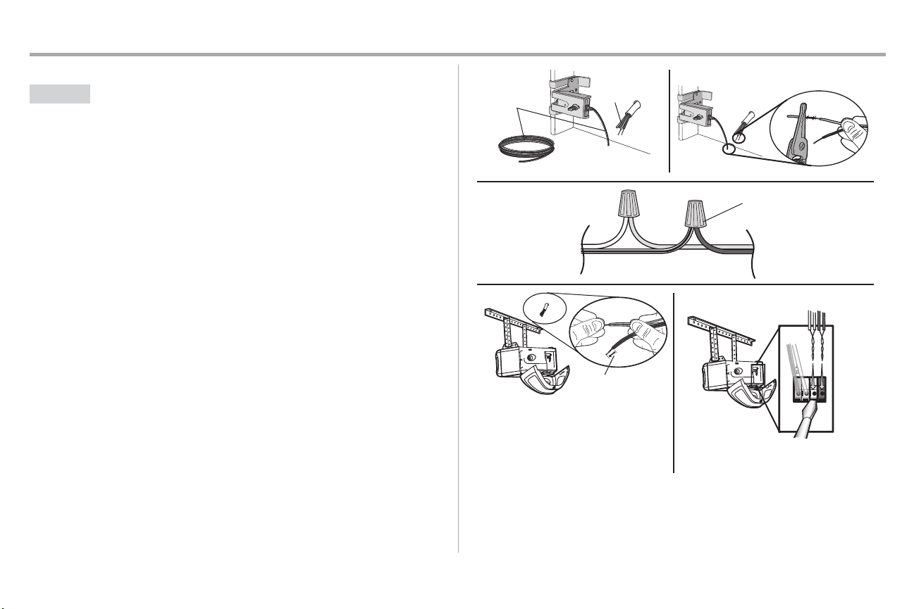
1. Cutthe end of the safetyreversing sensor wire, making sure there is enough wire to reach the
pre-installed wires from the wall.
2. Separate the safetyreversing sensor wires and strip 7/16 inch (11 mm) of insulation from each
end. Choose twoof the pre-installed wires and strip 7/16 inch (11 mm) of insulation from each
end. Make sure that you choose the same color pre-installed wires for each sensor.
3. Connectthe pre-installed wires to the sensor wires with wire nuts making sure the colors
correspond for each sensor. For example, the white wire would connect to the yellow wire and
the white/black wire would connect to the purple wire.
4. At the garage door opener, strip 7/16 inch (11 mm) of insulation from each end of the wires
previously chosen for the safetyreversing sensors.Twist the like-colored wires together.
5. Insertthe wires connected to the white safetysensor wires to the white terminal on the garage
door opener. Insertthe wires that are connected to the white/blacksafetysensor wires to the
grey terminal on the garage door opener.
25
Page 27
Installation
Ground Tab
Green
Ground
Screw
Ground
Wire
White Wire
Black
Wire
Black
Wire
STEP 15 Connect power
To prevent possible SERIOUSINJURY or DEATH from electrocution or fire:
• Be sure power is NOT connected to the opener, and disconnectpower to circuit BEFORE
removing cover to establish permanent wiring connection.
• Garage door installation and wiring MUSTbe in compliance withALL local electrical and building
codes.
• NEVER use an extension cord, 2-wire adapter, or change plug in any way to make it fitoutlet. Be
sure the opener is grounded.
To avoid installation difficulties, do not activate the garage dooropener at this time.
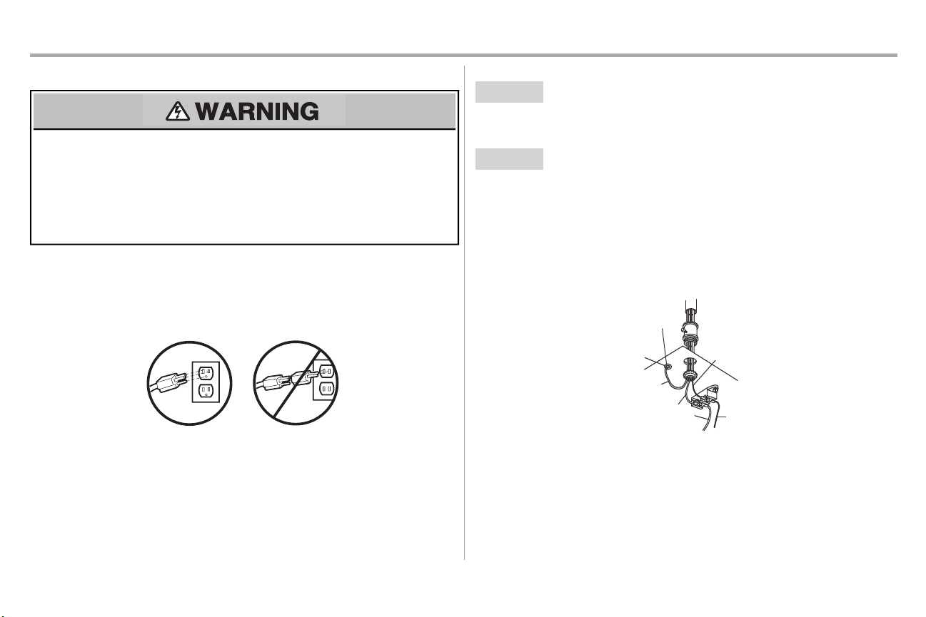
To reduce the riskof electric shock,your garage door opener has a grounding type plug with a third
grounding pin. This plug will only fitinto a grounding type outlet. If the plug doesn’t fitinto your outlet,
contacta qualified electrician to install the proper outlet.
THERE ARE TWO OPTIONS FOR CONNECTINGPOWER:
OPTION A
1. Plug in the garage door opener into a grounded outlet.
2. DO NOTrun garage door opener at this time.
OPTION B
If permanent wiring is required by yourlocal code, refer to the following procedure. To make a
permanent connection throughthe 7/8 inch hole in the top of the motor unit (accordingto local
code):
1. Removethe motor unit cover screwsand set the cover aside.
2. Removethe attached 3-prong cord.
3. Connectthe black (line) wire to the screwon the brass terminal; the white (neutral) wire to the
4. Reinstallthe cover.
TYPICAL WIRING
PERMANENT WIRING
screwon the silver terminal; and the ground wire to the green ground screw.The opener
must be grounded.
26
Page 28
Installation
Green LED
Amber LED
If the receiving sensor is in direct sunlight,
switch it with sending sensor so it is on the
opposite side of the door.
(invisible light beam)
SENDING SENSOR RECEIVING SENSOR
RED
WHITE
WHITE
GREY
3
2
1
1
2
STEP 16 Ensure the safety reversing sensors are aligned
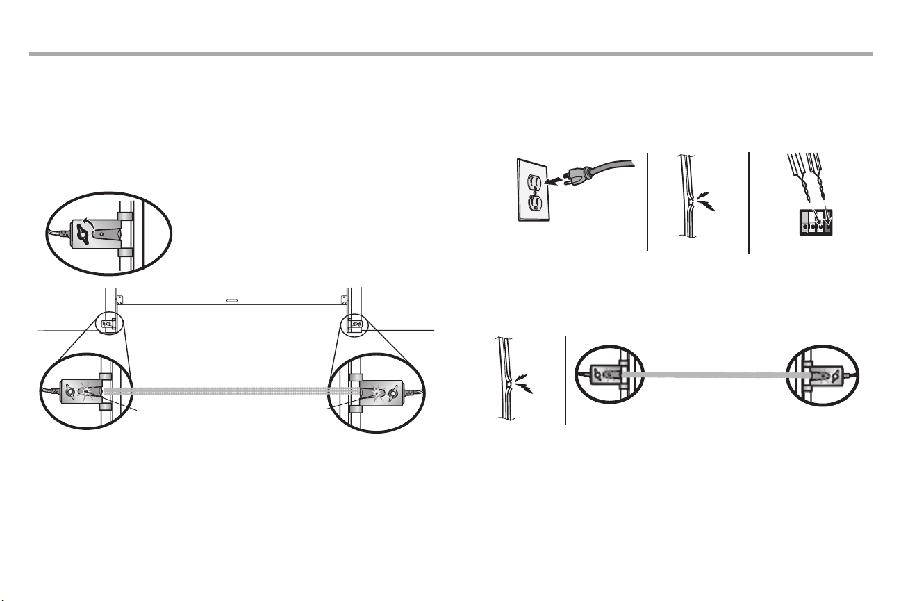
The doorwillnot close if the sensors have not been installedand alignedcorrectly.
When the light beam is obstructed or misaligned while the door is closing, the door will reverse and the
garage door opener lights will flash ten times.Ifthe door is already open, it will not close. The sensors
can be aligned by loosening the wing nuts,aligning the sensors, and tightening the wing nuts.
Checkto make sure the LEDsin both sensors are glowing steadily.The LEDs in both sensors will glow
steadilyif they are aligned and wired correctly.
IFTHE AMBER LED ON THE SENDING SENSOR IS NOT GLOWING:
1. Make sure there is power to the garage door opener.
2. Make sure the sensor wire is not shorted/broken.
3. Make sure the sensor has been wired correctly:white wires to white terminal and white/black
wires to grey terminal.
IFTHE GREEN LED ON THE RECEIVING SENSOR IS NOT GLOWING:
1. Make sure the sensor wire is not shorted/broken.
2. Make sure the sensors are aligned.
STEP 17 Ensure the door control is wired correctly
Ifthe door control has been installed and wired correctly,the command LED on the Multi-Function
Control Panel will blink.
27
Page 29
Adjustments
UP (Open)
DOWN (Close)
CORRECT
INCORRECT
UP Button
Adjustment
Button
DOWN Button
PROGRAMMING BUTTONS
Introduction
Withouta properly installed safetyreversal system, persons (particularly small children) could be
SERIOUSLY INJUREDor KILLED by a closing garage door.
• Incorrectadjustmentof garage door travel limitswill interfere with proper operation of safety
reversal system.
• AfterANY adjustments are made, the safetyreversal system MUSTbe tested.Door MUST reverse
on contactwith 1-1/2" (3.8 cm) high object(or 2x4 laid flat) on floor.
To prevent damage to vehicles,be sure fully open door provides adequate clearance.
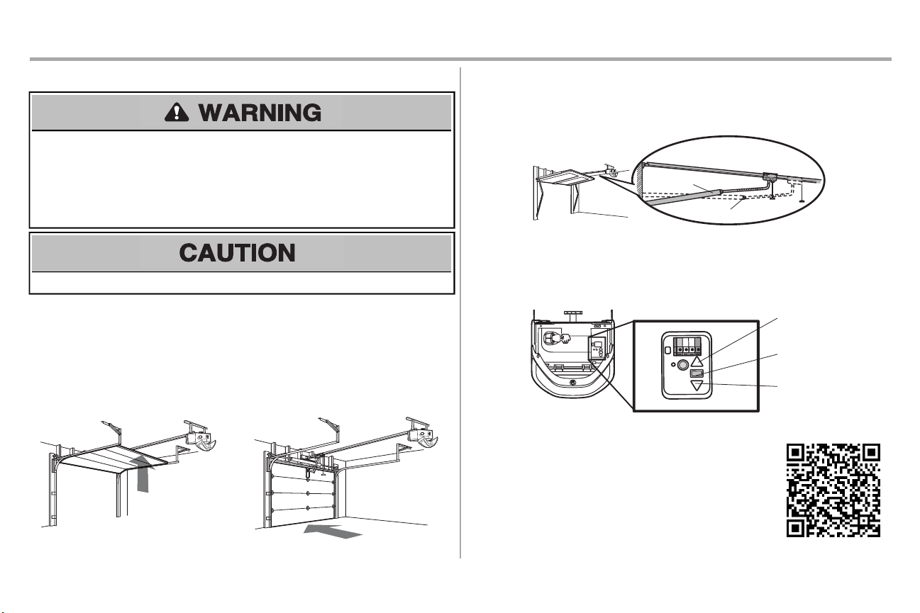
Your garage door opener is designed with electroniccontrols to make setup and adjustments easy.The
adjustmentsallow you to program where the door will stop in the open (UP) and close (DOWN) position.
The electronic controls sense the amount of force required to open and close the door. The force is
adjusted automatically when you program the travel.
Ifanything interferes with the door’s upward travel it will stop.Ifanything interferes withthe door’s
downward travel,it will reverse.
One-Piece Doors Only
When settingthe UP travel for a one-piece door ensure that the door does not slant backwards when
fullyopen (UP). If the door is slanted backwardsthis will cause unnecessary bucking and/or jerking
when the door is opening or closing.
Programming Buttons
The programming buttons are located on the left side panel of the garage door opener and are used
to program the travel.
To watch a short instructional video on howto program the travel on
your new garage door opener use your smartphone to read the QR
Code:
28
Page 30
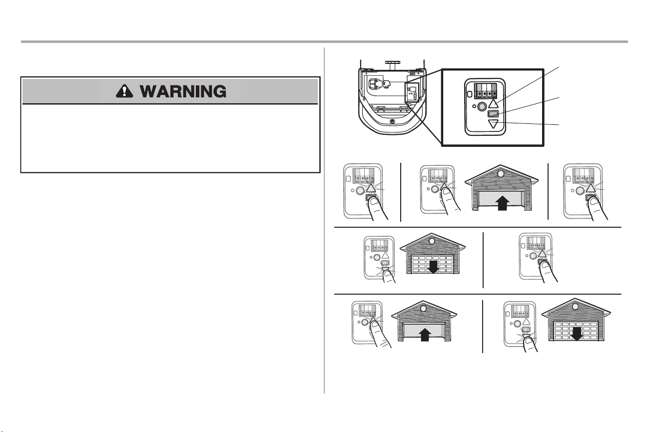
Adjustments
UP Button
Adjustment
Button
DOWN Button
PROGRAMMING BUTTONS
1 2
3
4 5
6 7
STEP1 Program the Travel
Withouta properly installed safetyreversal system, persons (particularly small children) could be
SERIOUSLY INJUREDor KILLED by a closing garage door.
• Incorrectadjustment of garage door travel limits will interfere with proper operation of safety
reversal system.
• After ANY adjustmentsare made, the safety reversal systemMUSTbe tested.Door MUST reverse
on contactwith 1-1/2" (3.8 cm) high object(or 2x4 laid flat) on floor.
1. Press and hold the Adjustment Button until the UP Buttonbegins to flash and/or a beep is
heard.
2. Press and hold the UP Button until the door is in the desired UP position.NOTE: The UPand
DOWNButtons can be used to move the door up and down as needed.
3. Once the door is in the desired UP position pressand releasethe Adjustment Button.The
* If the garage door opener lights are flashing 5 timesduring the stepsfor Program the Travel, the
programming has timed out. If the garage door opener lights are flashing 10 times during the stepsfor
Program the Travel, the safetyreversing sensors are misaligned or obstructed (refer to page 28). When
the sensorsare aligned and unobstructed,cycle the door through a complete up and down cycleusing
the remote control or the UP and DOWNbuttons.Programming is complete. If you are unable to operate
the door up and down, repeat the stepsfor Programming the Travel.
garage door opener lights will flash twice and the DOWN Buttonwill begin to flash.
4. Press and hold the DOWN Button until the door is in the desired DOWN position.NOTE: The
UPand DOWNButtonscan be used to move the door up and down as needed.
5. Once the door is in the desired DOWN position press and release the AdjustmentButton.The
garage door opener lights will flash twice and the UP Button will begin to flash.
6. Press and release the UP Button. When the door travels to the programmed UP position, the
DOWNButton will begin to flash.
7. Press and release the DOWN Button.The door will travel to the programmed DOWN position.
Programming is complete.
29
Page 31
Adjustments
1 2
1
2
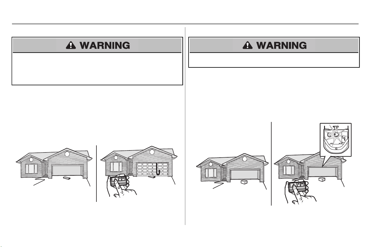
STEP 2 Test the Safety Reversal System
Withouta properly installed safetyreversal system, persons (particularly small children) could be
SERIOUSLY INJUREDor KILLED by a closing garage door.
• Safetyreversal system MUST be testedevery month.
• AfterANY adjustments are made, the safetyreversal system MUSTbe tested.Door MUST reverse
on contactwith 1-1/2" (3.8 cm) high object(or 2x4 laid flat) on the floor.
1. Withthe door fully open, place a 1-1/2 inch (3.8 cm) board (or a 2x4 laid flat) on the floor,
centered under the garage door.
2. Press the remote control push button to close the door.The door MUSTreverse when it makes
contactwith the board.
Ifthe door stops and does not reverse on the obstruction,the down travel needs to be increased (refer to
AdjustmentStep 1). Repeat the test. When the door reverses upon contactwith the 1-1/2 inch board,
remove the board and open/close the door 3 or 4 timesto testthe adjustment.If the garage door opener
continues to fail the safetyreversal test,call a trained door systemstechnician.
STEP 3 Test the Protector System
Without a properly installed safetyreversing sensor, persons (particularly small children) could be
SERIOUSLY INJURED or KILLED by a closing garage door.
1. Open the door. Place the garage door opener carton in the path of the door.
2. Press the remote control push button to close the door.The door will not move more than an
inch (2.5 cm),and the garage door opener lightswill flash 10 times.
The garage door opener will not close from a remote control if the LED in either safetyreversing sensor
is off (alerting you to the factthatthe sensor is misaligned or obstructed).If the garage door opener
closesthe door when the safetyreversing sensor is obstructed (and the sensors are no more than 6
inches [15 cm] above the floor), call for a trained door systemstechnician.
®
30
Page 32
Operation
IMPORTANT SAFETYINSTRUCTIONS
To reduce the risk of SEVERE INJURY or DEATH:
1. READ ANDFOLLOW ALL WARNINGS AND INSTRUCTIONS.
2. ALWAYS keep remotecontrols out of reach of children. NEVER permitchildren to operate or
play withgarage door control push buttonsor remote controls.
3. ONLY activate garage door when it can be seen clearly, it is properly adjusted,and there are
no obstructionsto door travel.
4. ALWAYS keep garage door in sight and away from people and objects until completely
closed. NO ONE SHOULD CROSS THE PATHOF THE MOVING DOOR.
5. NO ONE SHOULD GO UNDERA STOPPED,PARTIALLY OPENEDDOOR.
6. Ifpossible, use emergencyrelease handle to disengage trolley ONLY when garage door is
CLOSED. Use caution when using the release with the door opener. Weak or brokensprings
or unbalanced door could result in an open door falling rapidlyand/or unexpectedlyand
increasing the riskof SEVEREINJURYor DEATH.
7. NEVER use emergency release handle unlessgarage doorway is clear of persons and
obstructions.
8. NEVER use handle to pull garage door open or closed. If rope knot becomes untied,you
could fall.
9. AfterANY adjustments are made, the safetyreversal system MUSTbe tested.
10. Safetyreversal system MUSTbe tested everymonth. Garage door MUSTreverse on
contactwith 1-1/2" (3.8 cm) high object (or a 2x4 laid flat) on the floor. Failure to adjust the
garage door opener properly increasesthe risk of SEVERE INJURY or DEATH.
11. ALWAYS KEEP GARAGE DOOR PROPERLY BALANCED(see page 2).An improperly
balanced door may NOT reverse when required and could result in SEVERE INJURY or
DEATH.
12. ALL repairs to cables,spring assemblies and other hardware, ALL of which are under
EXTREME tension, MUSTbe made bya trained door systemstechnician.
13. ALWAYS disconnectelectricpower to garage door opener BEFORE making ANY
repairs or removing covers.
14. This operator system is equipped with an unattended operation feature. The door could
move unexpectedly.NO ONE SHOULDCROSS THE PATH OF THE MOVING DOOR.
15. DO NOT enable the Timer-to-Close functionality if operating either one-piece or
swinging garage doors. To be enabled ONLY when operating a sectional door.
16. SAVE THESE INSTRUCTIONS.
31
Page 33
Operation
MyQ® Accessories MEMORY CAPACITY
Remote Controls
Door Controls
Keyless Entries
Up to 8
Up to 2 MyQ® door controls
Up to 1
Features
Your garage door opener is equipped with features to provide you with greater control over your garage
door operation.
TIMER-TO-CLOSE (TTC) (Not available on all models)
The Timer-to-Close feature automaticallyclosesthe door after a specified timeperiod that can be
adjusted using the door control. DO NOT enable TTC if operating a one-piece door.TTC is to be used
ONLY with sectional doors. Factory default is set to off.The garage door opener will beep and the lights
will flashbefore closing the door. The TTC feature will deactivate if the garage door encounters an
obstruction twice;or the safetyreversing sensorsare incorrectlyinstalled. The garage door will reverse
open and WILL NOT close until the obstructionsare clear or the safetyreversing sensorsare correctly
installed.When the obstruction has been cleared orthe safetyreversing sensors have been aligned, the
door will close when the garage door opener is activated.TTCWILL NOT work if the garage door opener
is operating by batterypower or ifthe safetyreversing sensors are misaligned. This feature is NOT
intended to be the primary method of closing the door. A keyless entry shouldbe installed in the event
of an accidentallock out when using this feature.
®
MyQ
MyQ®technology usesa 900MHzsignal to provide two-waycommunication between the garage door
opener and MyQ®enabled accessories. Your garage door opener is compatible with up to 8 MyQ
accessories.
REMOTE CONTROLS AND DOOR CONTROLS (MyQ®)
Your garage door opener has already been programmed atthe factoryto operate with your remote
control,which changes witheach use, randomly accessing over 100 billion new codes.Compatible with
MyQ®enabled accessories, see page 40.
NOTE: Older Chamberlain remote controls,door controls, and third party products are not compatible.
®
THE PROTECTOR SYSTEM®(SAFETY REVERSING SENSORS)
When properly connectedand aligned, the safetyreversing sensors will detectan obstructionin the path
of the infrared beam.Ifan obstruction breaks the infrared beamwhile the door isclosing,the door will
stopand reverse to full open position, and the opener lights will flash 10 times.If the door is fullyopen,
and the safetyreversing sensors are notinstalled, or are misaligned, the door will not close from a
remote control. However,you can close the door if you hold the button on the door control or keyless
entry until the door is fully closed. The safetyreversing sensors do not effectthe opening cycle.
ENERGY CONSERVATION
For energy efficiencythe garage door opener will enter sleep mode when the door is fully closed.The
sleep mode shutsthe garage door opener down until activated. The sleep mode issequenced with the
garage door opener light bulb; as the light bulb turns off the sensor LEDs will turn offand whenever the
garage door opener lights turn on the sensor LEDs will light.The garage door opener will notgo into the
sleep mode until the garage door opener has completed 5 cyclesupon powerup.
LIGHTS
The garage door opener light bulbs will turn on when the opener isinitially plugged in; power is restored
afterinterruption,or when the garage door opener is activated.The lights will turn off automatically after
4-1/2 minutes.An incandescent A19 lightbulb (100 watt maximum) or for maximumenergy efficiencya
26W (100W equivalent) compact fluorescent light (CFL) bulb may be used. NOTE: Do not use halogen,
short neck, or specialty light bulbs as these may overheat the end panel or light socket. Do not use LED
bulbs as they may reduce the range or performance of your remote controls.
Light Feature
The garage door opener is equipped with an added feature;the lights will turn on when someone enters
through the open garage door and the safetyreversing sensor infrared beam is broken. For added
control over the light bulbs on your garage door opener, see page 33.
32
Page 34
Operation
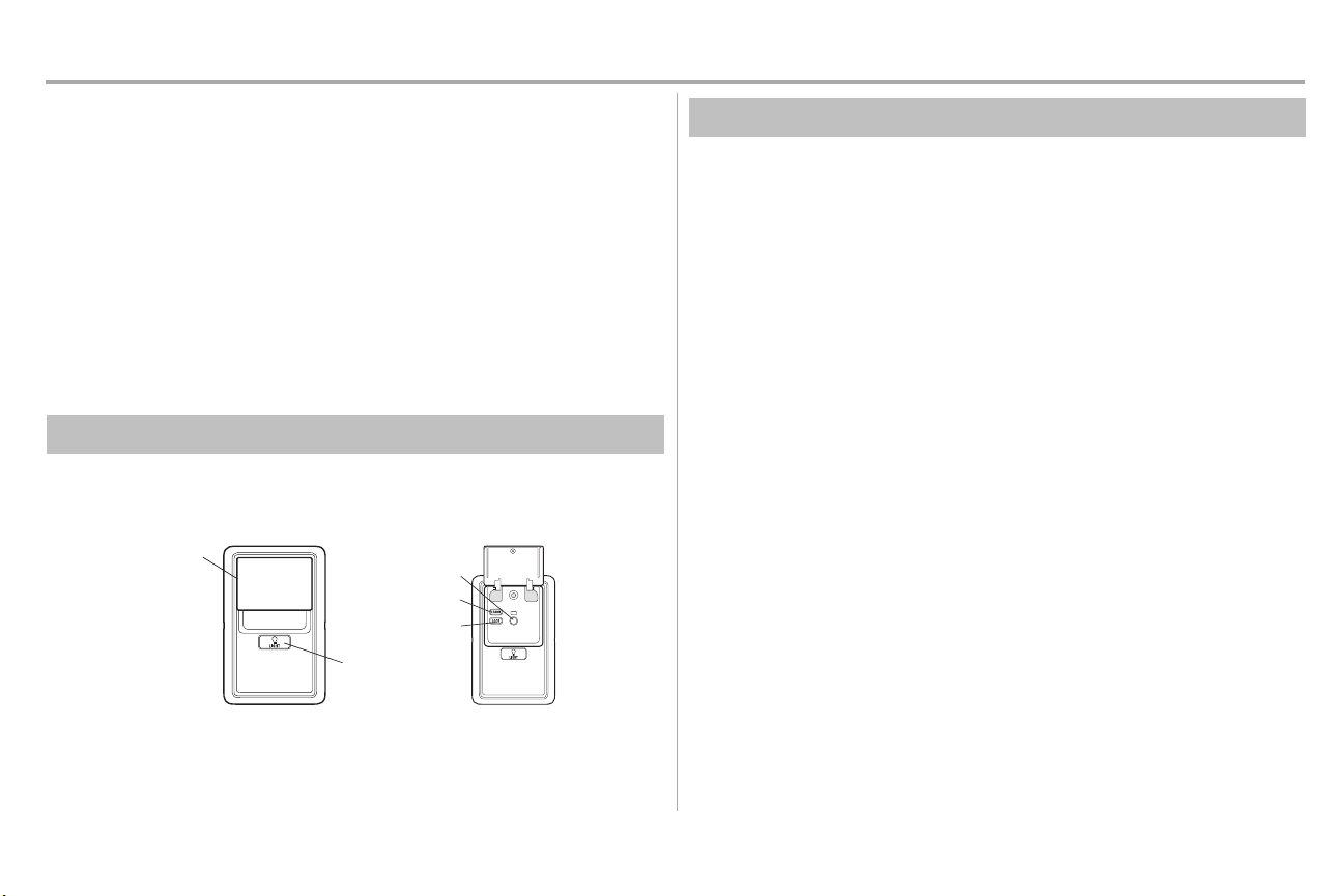
Push Bar
LIGHT Button
LOCK Button
Command LED
LEARN Button
Using your Garage Door Opener
The garage door opener can be activated through awall-mounted door control,remote control, wireless
keylessentryor MyQ®accessory.
When the door is closed and the garage door opener is activated the door will open. If the door senses
an obstruction or is interrupted while opening the door will stop. When the door is in anyposition other
than closed and the garage door opener is activatedthe door will close.If the garage door opener
sensesan obstruction while closing, the door will reverse.If the obstruction interrupts the sensor beam
the garage door opener lights will blink 10 times.However,you can close the door if you hold the button
on the door control or keyless entryuntil the door isfully closed. The safetyreversing sensors do not
affect the opening cycle.
The safety reversing sensor must be connected and aligned correctlybefore the garage door opener will
move in the down direction.
Using the Multi-Function Control Panel
SYNCHRONIZE THE DOOR CONTROL
To synchronize the door control to the garage door opener, press the push bar until the garage door
opener activates(it may take up to 3 presses). Test the door control by pressing the push bar, each press
of the push bar will activate the garage door opener.
MULTI-FUNCTIONCONTROLPANEL FEATURES
PUSH BAR
Press the push bar to open or close the door.
LIGHTS
Light Button
Press the LIGHT button to turn the garage door opener lightson or off.When the lights are turned on
theywill stayon until the LIGHTbutton is pressedagain, or until the garage door opener is activated.
Once the garage door opener is activated the lights will turn off after the specified period of time (the
factory setting is 4-1/2 minutes).The LIGHTbutton will not control the lightswhen the door is in motion.
To change the amountof time the garage dooropenerlights will stay on:
Press and hold the LOCK button (approximately10 seconds) until the garage door opener lightsflash.
The timeinterval is indicated by the number timesthe garage door opener flashes:
l
1 flash is 1-1/2 minutes
l
2 flashesis 2-1/2 minutes
l
3 flashesis 3-1/2 minutes
l
4 flashesis 4-1/2 minutes
To cycle through the time intervalsrepeat the step above.
Light Feature
The lights will turn on when someone enters through the open garage door and the safetyreversing
sensor infrared beam is broken.
l
Deactivate: Press and hold the LIGHTbutton (approximately 10 seconds) until the garage
door opener lights turn on, then offagain.
l
Activate: Start with the garage door opener lightson. Press and hold the LIGHTbutton
(approximately 10 seconds) until the garage door opener lights turn off,then on again.
Ifthe command LED is continuously blinking, the LOCK feature needs to be deactivated.
33
Page 35
Operation
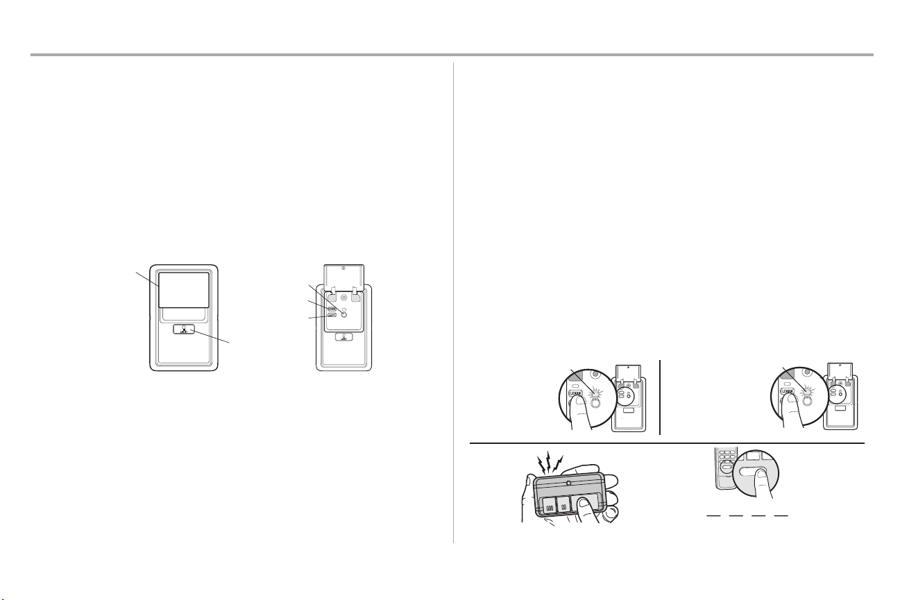
Push Bar
LIGHT Button
LOCK Button
Command LED
LEARN Button
The command LED
will flash once.
The command LED will
flash once again.
1
2
OR
PIN
? ? ? ?
4
GHI
5
JKL
7
P
RS
8
TUV
9
WXY
0
QZ
*
#
E
NT
E
R
0 QZ
*
#
ENTER
6
MNO
3
Motion Detecting Control Panel (continued)
LOCK
The LOCK feature is designed to prevent activation of the garage door opener from remote controls
while stillallowing activation from the door control and keylessentry. This feature is usefulfor added
peace of mind when the home is empty(i.e. vacation).
l
Activate: Press and hold the LOCK button for 2 seconds. The command LED will flash as
long as the lock feature is activated and your handheld remote control will not operate your
door at this time.
l
Deactivate: Press and hold the LOCK button again for 2 seconds. The command LED will
stopflashing and normaloperation will resume.
PROGRAM
Any compatible remote controls, wireless keylessentry,or MyQ®accessories can be programmed to the
garage door opener by pressing the Learn button.
Remote Control
Yourremote control has been programmed at the factory to operate with yourgaragedooropener.
Older Chamberlain remote controlsare NOTcompatible, see page 40 for compatible accessories.
Programming can be done through the door control or the learn button the garage door opener. To
program additional accessories refer to the instructions provided with the accessory or visit
www.chamberlain.com.If your vehicle is equipped with a Homelink®, you may require anexternal
adapter depending on the make,model, and year of your vehicle. Visit www.homelink.comfor additional
information.
TO ADD, REPROGRAM, OR CHANGE A REMOTE CONTROL/KEYLESS ENTRY PIN
USING THE MULTI-FUNCTIONCONTROLPANEL
1. Press the LEARNbutton on the door control to enter Programming Mode.
2. Press the LEARNbutton again,the LED will flash once.
3. Remote Control:
Press the button on the remote control that you wish to operate your garage door.
Keyless Entry:
Enter a 4-digit personal identification number (PIN) of your choice on the keylessentry
keypad.Then pressthe ENTERbutton.
The garage door opener lights will flash (or two clickswill be heard) when the code has been
programmed. Repeat the steps for programming additional remote controls or keyless entrydevices.
34
Page 36
Operation
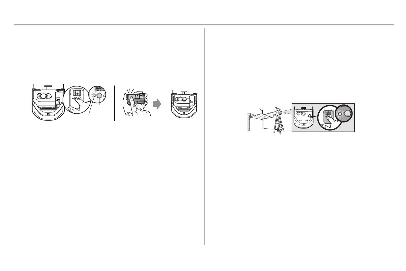
LEARN LED
LEARN
Button
“click”
“click”
1
2
Remote Control (continued)
PROGRAM A REMOTE CONTROL USING THE LEARN BUTTON
1. Locate the Learn Button.
2. Press and immediately release the Learn button.The Learn LEDwill glow steady for 30
seconds.Within 30 seconds...
3. Press and hold the buttonon the remotecontrol that you wish to use.
Release the button when the garage door opener lightsblink or two clicksare heard.
When replacing the light lens cover, ensure the antenna wires are hanging straight down.
To Erase the Memory
ERASE ALL REMOTE CONTROLS AND KEYLESS ENTRIES
1. Press and hold the learn button on garage door opener until the learn LED goes out
(approximately 6 seconds).All remotecontrol and keyless entrycodes are now erased.
Reprogram any accessory you wishto use.
ERASE ALL DEVICES (Including MyQ®enabled accessories)
1. Press and hold the learn button on garage door opener until the learn LED goes out
(approximately 6 seconds).
2. Immediately pressand hold the learn button again until the learn LED goes out. All codes are
now erased.
Reprogram any accessory you wishto use.
35
Page 37
Operation
NOTICE
N
O
TICE
To Open the Door Manually
To prevent possible SERIOUSINJURY or DEATH from a falling garage door:
• Ifpossible, use emergencyrelease handle to disengage trolley ONLY when garage door is
CLOSED. Weak or broken springs or unbalanced door could resultin an open door falling
rapidly and/or unexpectedly.
• NEVER use emergency release handle unlessgarage doorway is clear of persons and
obstructions.
• NEVER use handle to pull door open or closed. Ifrope knot becomes untied, you could fall.
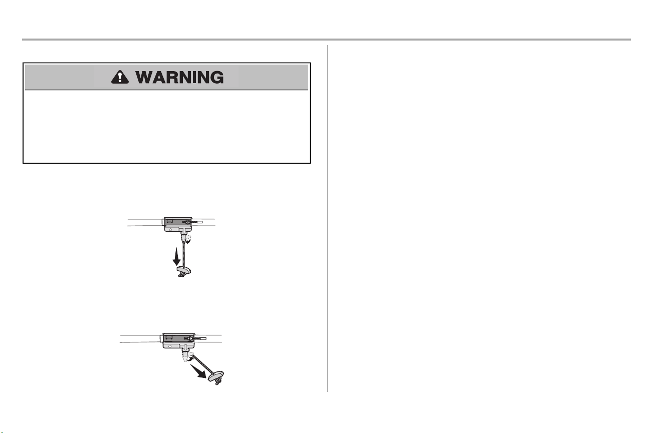
DISCONNECTTHE TROLLEY
1. The door should be fully closed if possible.
2. Pull down on the emergency release handle so the trolley release arm snaps to the vertical
position.The door can now be raised and lowered as often as necessary.
RECONNECT THE TROLLEY
1. Pull the emergency release handle toward the garage door opener so the trolley release arm
snaps to the horizontal position.
The trolley will reconnecton the next UP or DOWN operation, either manually or by using the
door control or remote control.
36
Page 38
Maintenance
1
2
3
Maintenance Schedule
EVERY MONTH
• Manually operate door. If it is unbalanced or binding, call a trained door systemstechnician.
• Checkto be sure door opensand closesfully. Adjustif necessary,see page 28.
• Testthe safety reversal system. Adjustif necessary,see page 28.
EVERY YEAR
• Oil door rollers,bearings and hinges.The garage door opener does not require additional
lubrication. Do not grease the door tracks.
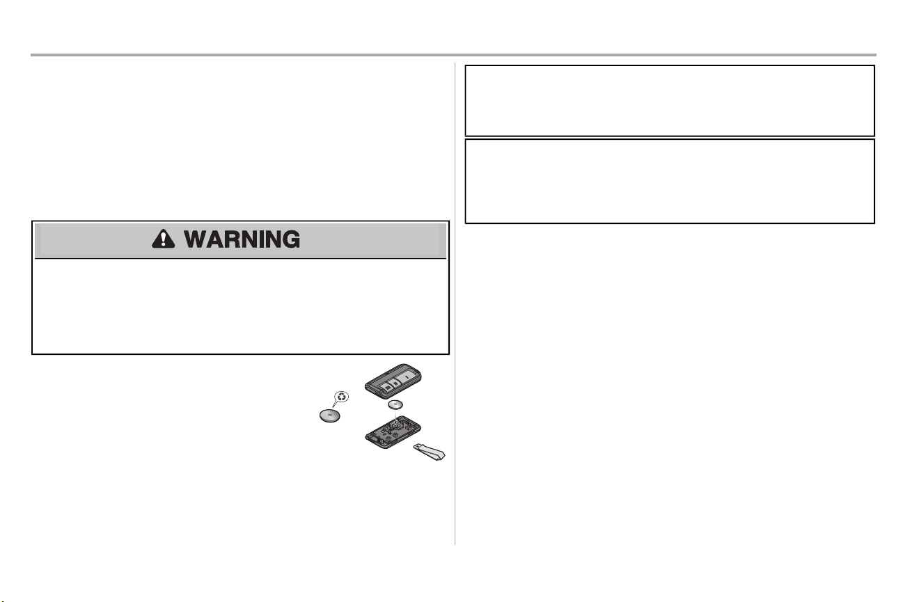
The Remote Control Battery
To prevent possible SERIOUSINJURY or DEATH:
• NEVER allow small children near batteries.
• Ifbatteryis swallowed,immediately notifydoctor.
To reduce risk of fire, explosion or chemical burn:
• Replace ONLY with 3V2032 coin batteries.
• DO NOTrecharge, disassemble, heat above 212°F (100°C) or incinerate.
The 3V2032 lithium batteryshould produce power for up to 5 years. If
the batteryis low,the remote control’s LED will not flash when the
button is pressed.
To replace battery,pry open the case firstin the middle (1), then at
each side (2 and 3) with the visor clip.
Replace the batterieswith only 3V2032 coin cell batteries.Insert
batterypositive side up. Dispose of old batteries properly.
NOTICE: To complywith FCC and/or Industry Canada (IC) rules, adjustment ormodificationsof thistransceiverare prohibited. THERE
ARENO USER SERVICEABLEPARTS.Any changes ormodifications not expresslyapproved b y the party responsible for compliance
could void the user'sauthorityto operate the equipment.
Thisdevicecomplieswith Part 15 of th e FCC rules and IC RSS-210 . Operation is subject to the following two conditions: (1) thisdevice
maynot cause harmfulinterference, and (2)thisdevice must accept any interference received, including interferen ce that may cause
undesired operation.
ThisClass Bd igitala pparatuscomplieswith Canadian ICES-003.
AVIS: Lesrèglesde la FCC et/ou d ’IndustrieCanada (IC)interdisent tout ajustement ou to ute modification de cerécepteur. IL
N’EXISTEAUCUNEPIÈCESUSCEPTIBLE D’ÊTREENTRETENUEPARL’UTILISATEUR. Tout changementou toute modification no n
expressément a pprouvé par la partieresponsable de laconformité peut avoirpour résultat d'annuler l'autoritéde l'utilisateur de faire
fonctionner l'équipement.
Cet a ppareilestconformeauxdispositionsde la partie 15 du règlement de la FCCetd e l'norme ICRSS-210. Son utilisation est
assujettie auxd euxconditoins suivantes :(1)cedispositifne peut cau serdes interférencesn uisibles,et (2)ce dispositifdoit accepter
toute interférence recue, y comprisune inte rférence pouvant causer un fonctionnement no n souhaité.
Cet a ppareilnumerique de la classeB estconforme a lanorme NMB-003 du Ca nada.
37
Page 39
Troubleshooting
Diagnostic Chart
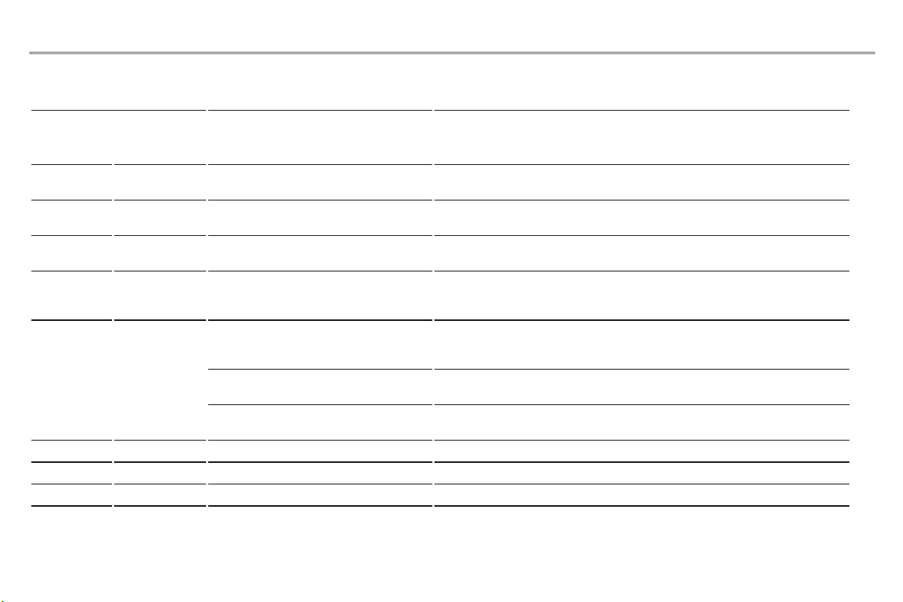
Your garage door opener is programmed with self-diagnosticcapabilities.The UP and DOWN arrows on the garage door opener flash the diagnosticcodes.
DIAGNOSTICCODE
Up Arrow
Flash(es)
1 1 The garage door opener will not close and the light
1 2 The garage door opener will not close and the light
1 3 The door control will not function. The wires for the door control are shorted or the door control is faulty.Inspectsafetysensor wire at all
1 4 The garage door opener will not close and the light
1 5 Door moves6-8" stops or reverses. Manually open and close the door. Checkfor binding or obstructions, such as a broken spring ordoor
1 6 Door coastsafterit has come to a complete stop. Program travel to coasting position or have door balanced by a trained door systemstechnician.
2 1-5 No movement, or sound. Replace logic board.
3 2 Unable to setthe travel or retain position. Checktravel module for proper assembly,replace if necessary.
Down Arrow
Flash(es)
SYMPTOM SOLUTION
bulbs flash.
bulbs flash.
bulbs flash.
No movement, only a single click. Manually open and close the door. Checkfor binding orobstructions,such as a broken spring or door
Opener hums for 1-2 seconds no movement. Manually open and close the door. Check for binding or obstructions,such as a brokenspring or door
Safetysensors are not installed, connected, or wires may be cut. Inspectsensor wires for a
disconnectedor cut wire.
There is a short or reversed wire for the safetysensors. Inspect safetysensor wire at all staple and
connection points,replace wire or correct as needed
staple pointsand connection points and replace wire or correct as needed.
Safetysensors are misaligned or were momentarily obstructed.Realign both sensors to ensure both
LEDs are steadyand notflickering. Make sure nothing is hanging ormounted on the door that would
interrupt the sensor’s path while closing.
lock,correctas needed. Check wiring connectionsat travel module and at the logic board. Replace
travel module ifnecessary.
lock,correctas needed. Replace logic board if necessary.
lock,correctas needed. Replace motor if necessary.
38
Page 40
Troubleshooting
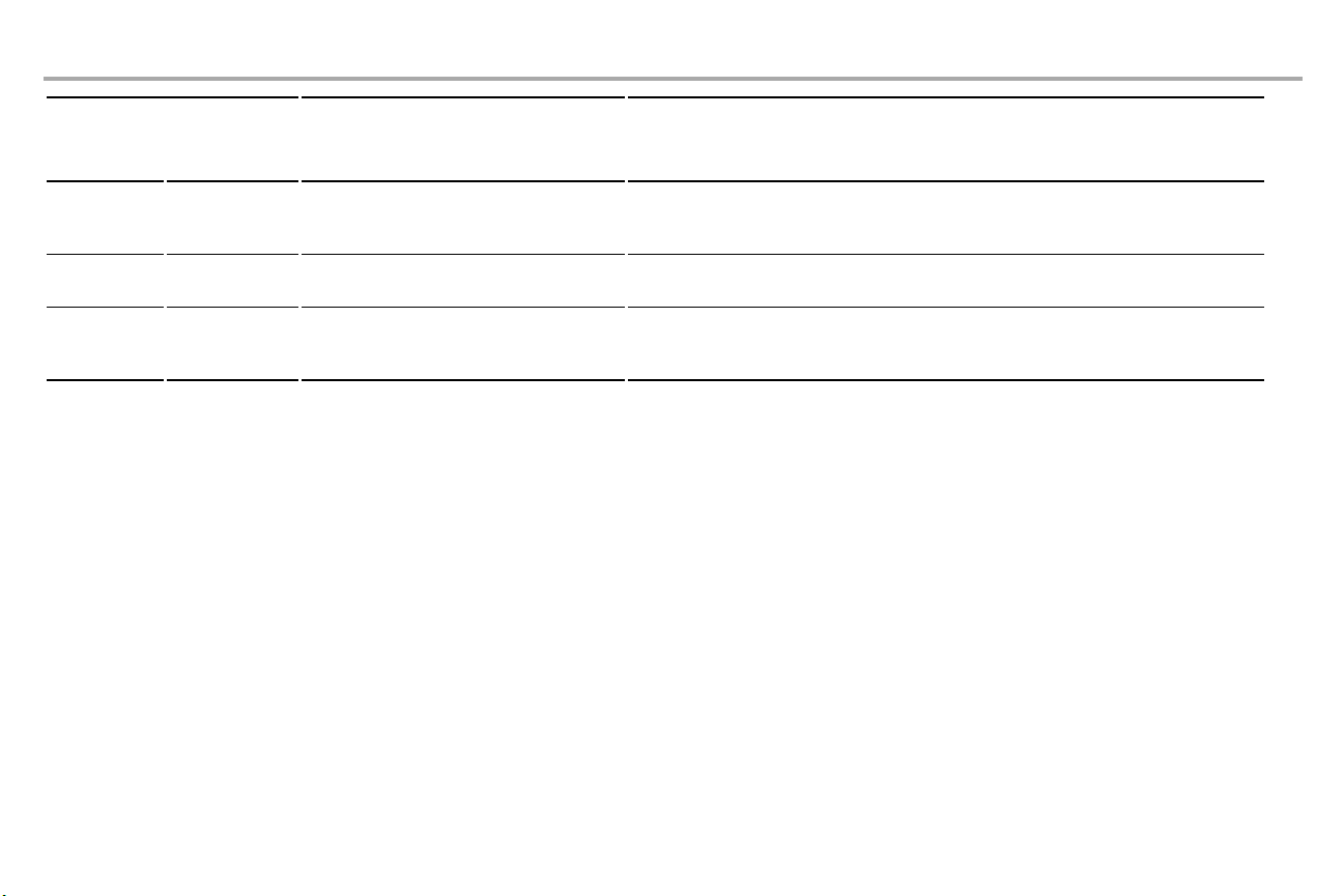
DIAGNOSTICCODE
Up Arrow
Flash(es)
4 1-4 Door is moving stops or reverses. Manually open and close the door. Checkfor binding or obstructions, such as a broken spring ordoor lock,
4 5 Opener runs approximately6-8",stops and reverses. Communicationerror to travelmodule.Check travel module connections,replace travel module if
4 6 The garage door opener will not close and the light
The garage door opener can beep for several reasons:
• Garage door opener has been activated through a device or feature such as Timer-toClose or garage door monitor, see page 32.
My remote control willnot activate the garage door:
• Verify the lock feature is not activated on the door control.
• Reprogram the remote control.
• Ifthe remote control will still not activate the door check the diagnosticcodes to ensure
the garage door opener is working properly.
My door will not close and the light bulbs blink on my motor unit:
The safety reversing sensor must be connected and aligned correctlybefore the garage
door opener will move in the down direction.
• Verify the safetysensors are properly installed,aligned and free of any obstructions.
Down Arrow
Flash(es)
SYMPTOM SOLUTION
correctas needed. If the door is binding orsticking contacta trained door systemstechnician. If door is not
binding or sticking attemptto reprogram travel (refer to page 28).
necessary.
bulbs flash.
Safetysensors are misaligned or were momentarily obstructed.Realign both sensors to ensure both LEDs
are steady and not flickering. Make sure nothing is hanging or mounted on the door that would interrupt
the sensor’spath while closing.
My garage dooropener light(s) willnot turn off when the door is open:
The garage door opener is equipped with a feature that turns the light on when the safetyreversing sensors
have been obstructed or when the motion sensor on the door control detects movement in the garage. These
featurescan be disabled using the door control, see page 33.
My neighbor’s remote controlopens my garage door:
Erase the memoryfrom your garage door opener and reprogram the remote control(s).
The LEDs on the doorcontrol blink:
Ifyou have a Smart Control Panel installed and the TTCis setto a customtime,press the ONbutton on the
Premium Motion-Detecting Control Panel to set the time properly.
My vehicle's Homelink®is not programmingto my garage dooropener:
Depending on the make,model, and year of your vehicle an external adapter may be required. Visit
www.homelink.com for additional information.
39
Page 41
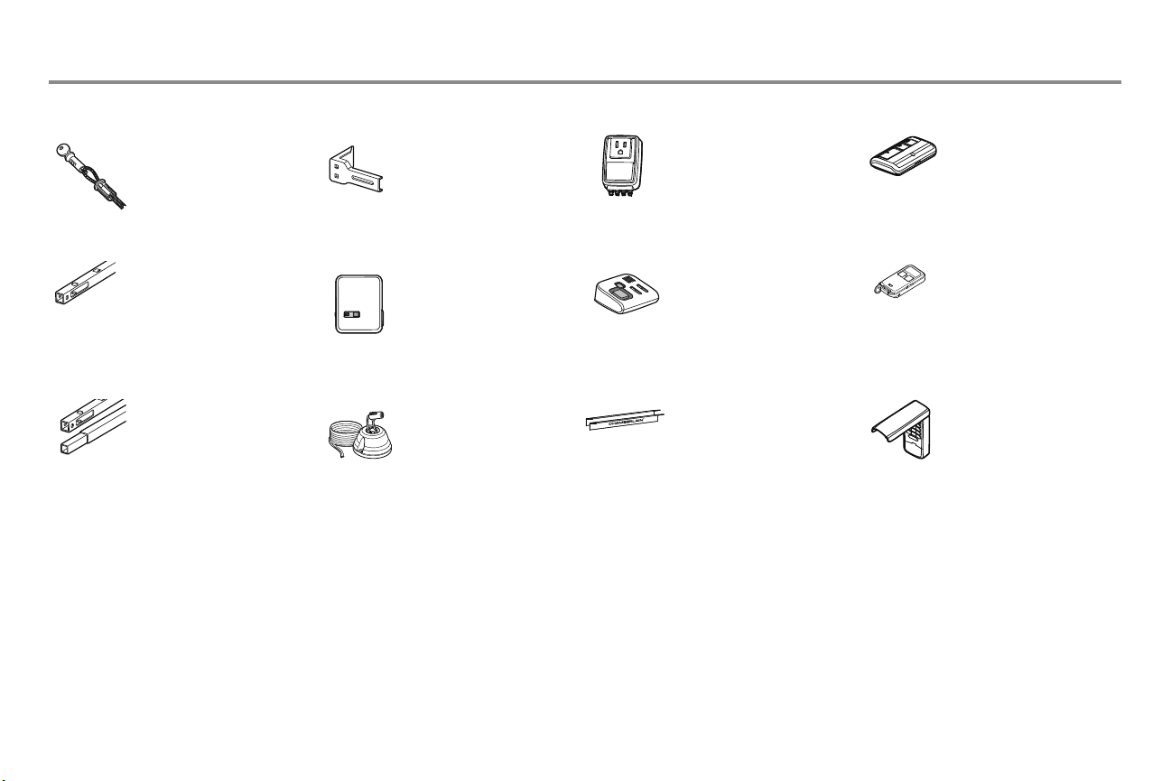
Accessories
7702CB
7708CB
7710CB
Outside Quick Release:
Required for a garage with NO
access door.
8 Foot (2.4 m) Rail Extension:
To allow an 8 foot (2.4 m) door
to open fully.
10 Foot (3 m) Rail Extension:
To allow a 10 foot (3 m) door
to open fully.
041A5281-1
PILCEV
CLLP1
Extension Brackets:
(Optional) For safety reversing
sensor installation onto the
wall or fl oor.
MyQ® Remote Light Control:
Control home lighting and
garage doors with one remote.
For use with plug-in lamps.
Synchronize to work with MyQ®
compatible garage door openers
and remote controls.
Laser Parking Assistant:
Park in the right spot every time!
A laser beam is activated by your
garage door opener and
projected on to the dashboard
of your vehicle to guide perfect
parking.
CLSS1
AGDMEV
BIK01
System Surge Protector:
The Garage Door Opener Surge
Protector is designed to protect
Chamberlain garage door
openers against damage from
lightning and power surges. Easy
to install.
Garage Door and Gate Monitor:
Monitor open/closed status for
up to 4 MyQ
door openers or gate operators
and close them from anywhere in
the home.
Installation Upgrade Kit:
The Installation Upgrade Kit
includes all components needed
to hang garage door openers up
to 24" (61 cm) from the ceiling.
®
compatible garage
953EV
956EV
940EV
Remote Control:
Works with ALL Chamberlain
openers from 1993-present.
®
compatible. Includes visor
MyQ
clip.
Keychain Remote Control:
Works with ALL Chamberlain
openers from 1993-present.
®
MyQ
compatible. With key ring.
Wireless Keypad:
For use outside of the home to
enable access to the garage
using a 4-digit PIN. Works with
ALL Chamberlain openers from
1993-present. MyQ® compatible.
40
Page 42

Warranty
®
CHAMBERLAIN
LIFETIME MOTOR LIMITED WARRANTY MODEL PD612EV
The Chamberlain Group, Inc.
residence in which this product is originally installed, that it is free from defects in materials and/
or workmanship for a period of two years from the date of purchase, except that the motor which is
warranted to be free from defects in materials and/or workmanship for the lifetime of the product.
The proper operation of this product is dependent on your compliance with the instructions regarding
installation, operation, and maintenance and testing. Failure to comply strictly with those instructions
will void this limited warranty in its entirety.
If, during the limited warranty period, this product appears to contain a defect covered by this limited
warranty, call 1-800-528-9131, toll free, before dismantling this product. You will be advised of
disassembly and shipping instructions when you call. Then send the product or component, pre-paid
and insured, as directed to our service center for warranty repair. Please include a brief description
of the problem and a dated proof-of-purchase receipt with any product returned for warranty repair.
Products returned to Seller for warranty repair, which upon receipt by Seller are confi rmed to be
defective and covered by this limited warranty, will be repaired or replaced (at Seller’s sole option) at
no cost to you and returned pre-paid. Defective parts will be repaired or replaced with new or factory
rebuilt parts at Seller’s sole option. [You are responsible for any costs incurred in removing and/or
reinstalling the product or any component.]
ALL IMPLIED WARRANTIES FOR THE PRODUCT, INCLUDING BUT NOT LIMITED TO ANY IMPLIED
WARRANTIES OF MERCHANTABILITY AND FITNESS FOR A PARTICULAR PURPOSE, ARE LIMITED
IN DURATION TO THE APPLICABLE LIMITED WARRANTY PERIOD SET FORTH ABOVE FOR THE
RELATED COMPONENT(S), AND NO IMPLIED WARRANTIES WILL EXIST OR APPLY AFTER SUCH
PERIOD. Some States do not allow limitations on how long an implied warranty lasts, so the
above limitation may not apply to you. THIS LIMITED WARRANTY DOES NOT COVER NON-DEFECT
DAMAGE, DAMAGE CAUSED BY IMPROPER INSTALLATION, OPERATION OR CARE (INCLUDING,
BUT NOT LIMITED TO ABUSE, MISUSE, FAILURE TO PROVIDE REASONABLE AND NECESSARY
MAINTENANCE, UNAUTHORIZED REPAIRS OR ANY ALTERATIONS TO THIS PRODUCT), LABOR
CHARGES FOR REINSTALLING A REPAIRED OR REPLACED UNIT, REPLACEMENT OF CONSUMABLE
ITEMS (E.G., BATTERIES IN REMOTE CONTROL TRANSMITTERS AND LIGHT BULBS), OR UNITS
INSTALLED FOR NON-RESIDENTIAL USE. THIS LIMITED WARRANTY DOES NOT COVER ANY
PROBLEMS WITH, OR RELATING TO, THE GARAGE DOOR OR GARAGE DOOR HARDWARE,
INCLUDING BUT NOT LIMITED TO THE DOOR SPRINGS, DOOR ROLLERS, DOOR ALIGNMENT
OR HINGES. THIS LIMITED WARRANTY ALSO DOES NOT COVER ANY PROBLEMS CAUSED BY
INTERFERENCE. UNDER NO CIRCUMSTANCES SHALL SELLER BE LIABLE FOR CONSEQUENTIAL,
INCIDENTAL OR SPECIAL DAMAGES ARISING IN CONNECTION WITH USE, OR INABILITY TO USE,
THIS PRODUCT. IN NO EVENT SHALL SELLER’S LIABILITY FOR BREACH OF WARRANTY, BREACH
OF CONTRACT, NEGLIGENCE OR STRICT LIABILITY EXCEED THE COST OF THE PRODUCT COVERED
HEREBY. NO PERSON IS AUTHORIZED TO ASSUME FOR US ANY OTHER LIABILITY IN CONNECTION
WITH THE SALE OF THIS PRODUCT.
Some states do not allow the exclusion or limitation of consequential, incidental or special damages,
so the above limitation or exclusion may not apply to you. This limited warranty gives you specifi c legal
rights, and you may also have other rights, which vary from state to state.
®
(“Seller”) warrants to the fi rst retail purchaser of this product, for the
TWO YEAR LIMITED WARRANTY
CHAMBERLAIN® TWO YEAR LIMITED WARRANTY
10 YEAR MOTOR LIMITED WARRANTY MODEL HD420EV
The Chamberlain Group, Inc.
residence in which this product is originally installed, that it is free from defects in materials and/
or workmanship for a period of two years from the date of purchase, except that the motor which is
warranted to be free from defects in materials and/or workmanship for a period of 10 years. The proper
operation of this product is dependent on your compliance with the instructions regarding installation,
operation, and maintenance and testing. Failure to comply strictly with those instructions will void this
limited warranty in its entirety.
If, during the limited warranty period, this product appears to contain a defect covered by this limited
warranty, call 1-800-528-9131, toll free, before dismantling this product. You will be advised of
disassembly and shipping instructions when you call. Then send the product or component, pre-paid
and insured, as directed to our service center for warranty repair. Please include a brief description
of the problem and a dated proof-of-purchase receipt with any product returned for warranty repair.
Products returned to Seller for warranty repair, which upon receipt by Seller are confi rmed to be
defective and covered by this limited warranty, will be repaired or replaced (at Seller’s sole option) at
no cost to you and returned pre-paid. Defective parts will be repaired or replaced with new or factory
rebuilt parts at Seller’s sole option. [You are responsible for any costs incurred in removing and/or
reinstalling the product or any component.]
ALL IMPLIED WARRANTIES FOR THE PRODUCT, INCLUDING BUT NOT LIMITED TO ANY IMPLIED
WARRANTIES OF MERCHANTABILITY AND FITNESS FOR A PARTICULAR PURPOSE, ARE LIMITED
IN DURATION TO THE APPLICABLE LIMITED WARRANTY PERIOD SET FORTH ABOVE FOR THE
RELATED COMPONENT(S), AND NO IMPLIED WARRANTIES WILL EXIST OR APPLY AFTER SUCH
PERIOD. Some States do not allow limitations on how long an implied warranty lasts, so the
above limitation may not apply to you. THIS LIMITED WARRANTY DOES NOT COVER NON-DEFECT
DAMAGE, DAMAGE CAUSED BY IMPROPER INSTALLATION, OPERATION OR CARE (INCLUDING,
BUT NOT LIMITED TO ABUSE, MISUSE, FAILURE TO PROVIDE REASONABLE AND NECESSARY
MAINTENANCE, UNAUTHORIZED REPAIRS OR ANY ALTERATIONS TO THIS PRODUCT), LABOR
CHARGES FOR REINSTALLING A REPAIRED OR REPLACED UNIT, REPLACEMENT OF CONSUMABLE
ITEMS (E.G., BATTERIES IN REMOTE CONTROL TRANSMITTERS AND LIGHT BULBS), OR UNITS
INSTALLED FOR NON-RESIDENTIAL USE. THIS LIMITED WARRANTY DOES NOT COVER ANY
PROBLEMS WITH, OR RELATING TO, THE GARAGE DOOR OR GARAGE DOOR HARDWARE,
INCLUDING BUT NOT LIMITED TO THE DOOR SPRINGS, DOOR ROLLERS, DOOR ALIGNMENT
OR HINGES. THIS LIMITED WARRANTY ALSO DOES NOT COVER ANY PROBLEMS CAUSED BY
INTERFERENCE. UNDER NO CIRCUMSTANCES SHALL SELLER BE LIABLE FOR CONSEQUENTIAL,
INCIDENTAL OR SPECIAL DAMAGES ARISING IN CONNECTION WITH USE, OR INABILITY TO USE,
THIS PRODUCT. IN NO EVENT SHALL SELLER’S LIABILITY FOR BREACH OF WARRANTY, BREACH
OF CONTRACT, NEGLIGENCE OR STRICT LIABILITY EXCEED THE COST OF THE PRODUCT COVERED
HEREBY. NO PERSON IS AUTHORIZED TO ASSUME FOR US ANY OTHER LIABILITY IN CONNECTION
WITH THE SALE OF THIS PRODUCT.
Some states do not allow the exclusion or limitation of consequential, incidental or special damages,
so the above limitation or exclusion may not apply to you. This limited warranty gives you specifi c legal
rights, and you may also have other rights, which vary from state to state.
41
®
(“Seller”) warrants to the fi rst retail purchaser of this product, for the
Page 43
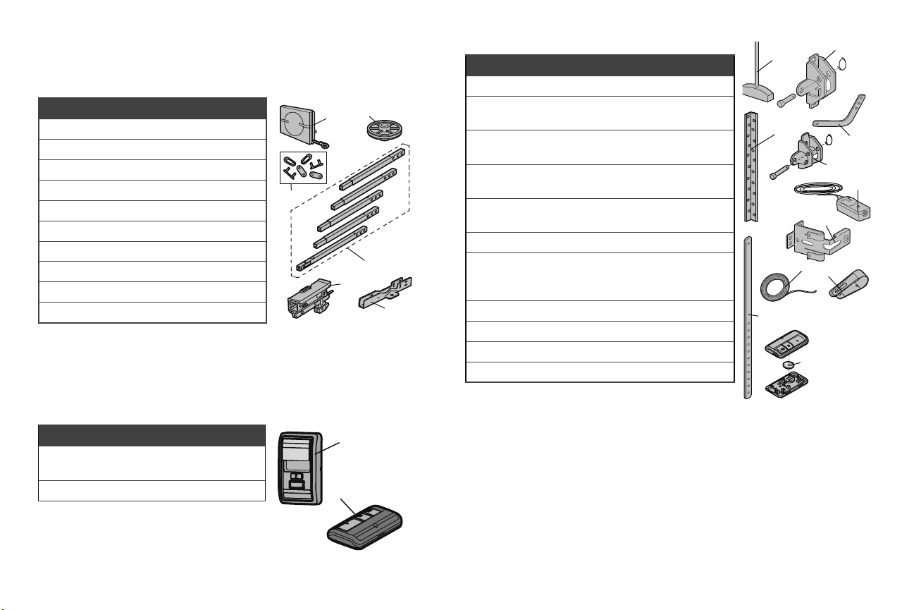
Repair Parts
Rail Assembly Parts
Description Part Number
1
Chain and Cable 41A5807
2
Pulley 144C56
3 Master Link 4A1008
4
Rail 41A5665
5 Trolley Assembly
6
“U” Bracket 12D598-1
Not Shown
Wear Pads 183A163
Hardware Bag 041A7920-1
Owner’s Manual
41C5141-1
114A4305
Installation Parts
3
2
Description Part Number
1 Curved Door Arm 178B35
2
1
3
4
5
6
2 Door Bracket with Clevis Pin and
Fastener
3 Emergency Release Rope and
Handle
4 Header Bracket with Clevis Pin and
Fastener
5 Remote Control
Visor Clip
6 Safety Sensor Bracket 041A5266-3
7 Safety Sensor Kit Receiving
and sending sensors with
2-conductor wire
8 Straight Door Arm 178B34
9 White and Red/White Wire 41B4494-1
10 3V2030 Lithium Battery 10A20
11 Hanging Brackets 12B776
41A5047-1
41A2828
41A5047-2
29B137
41A5034
NOTICE
11
9
8
10
1
4
7
6
5
Accessories
Description Part Number
1 Multi-Function Control
Panel
2 Remote Control 953ESTD
41A7185-1
Contact Information
For installation and service information call:
1
Before calling, please have the model number of the garage door opener. If you are calling
about a Troubleshooting issue, it is recommended that you have access to your garage door
2
opener while calling. If you are ordering a repair part please have the following information:
42
1-800-528-9131
part number, part name, and model number.
Address repair parts orders to:
The Chamberlain Group, Inc.
6050 S. Country Club Road
Tucson, AZ 85706
Page 44
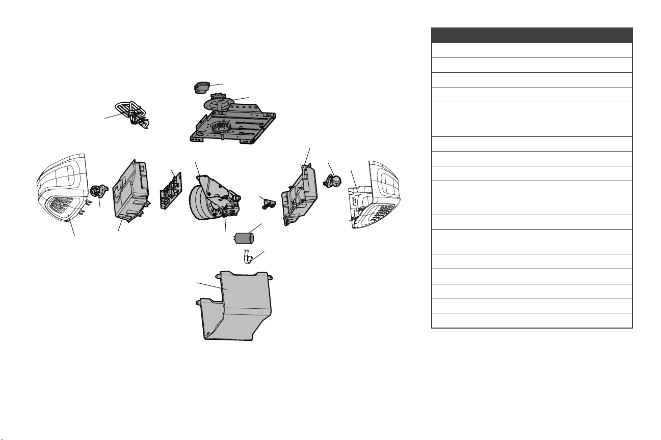
Repair Parts
Garage Door Opener Parts
13
4
5
11
10
12
9
Description Part Number
1 Chain Spreader 41A5615
2 Gear and Sprocket 41C4220A
1
2
3
4
5
14
6
8
7
3 End Panel with Light Socket 41A7760
4 Light Socket 41C279
5 Light Lens
Model HD420EV
Model PD612EV
6 Capacitor 30B532
7 Capacitor Bracket 12A373
8 Travel Module 41D7742-7
9 Cover
Model HD420EV
Model PD612EV
10 Receiver Logic Board 45ACT
11 End Panel for Receiver Logic Board
with Light Socket
12 Motor with Travel Module 41D7440
13 Line Cord 41B4245
14 Terminal Block 41A3150
Not Shown
Wire Harness Kit 41A7945
41D7572
41D7570
41A7620-7
41A7620-10
41D7638
114A4305D All Rights Reserved
© 2013, The Chamberlain Group, Inc.
43
 Loading...