

Page 1
ROLLING CODE
M
o
d
e
l
8
4
3
35
E
M
L
TM
TM
Illustrated Instruction Manual
for ML500 Garage Door Operator
Chamberlain Australia Pty Ltd
PO Box 1446
Lane Cove NSW 1595
www.motorlift.com.au
Chamberlain New Zealand Ltd
P.O. Box 100-221
Auckland 1330
www.motorlift.co.nz
Page 2

2
Page 3
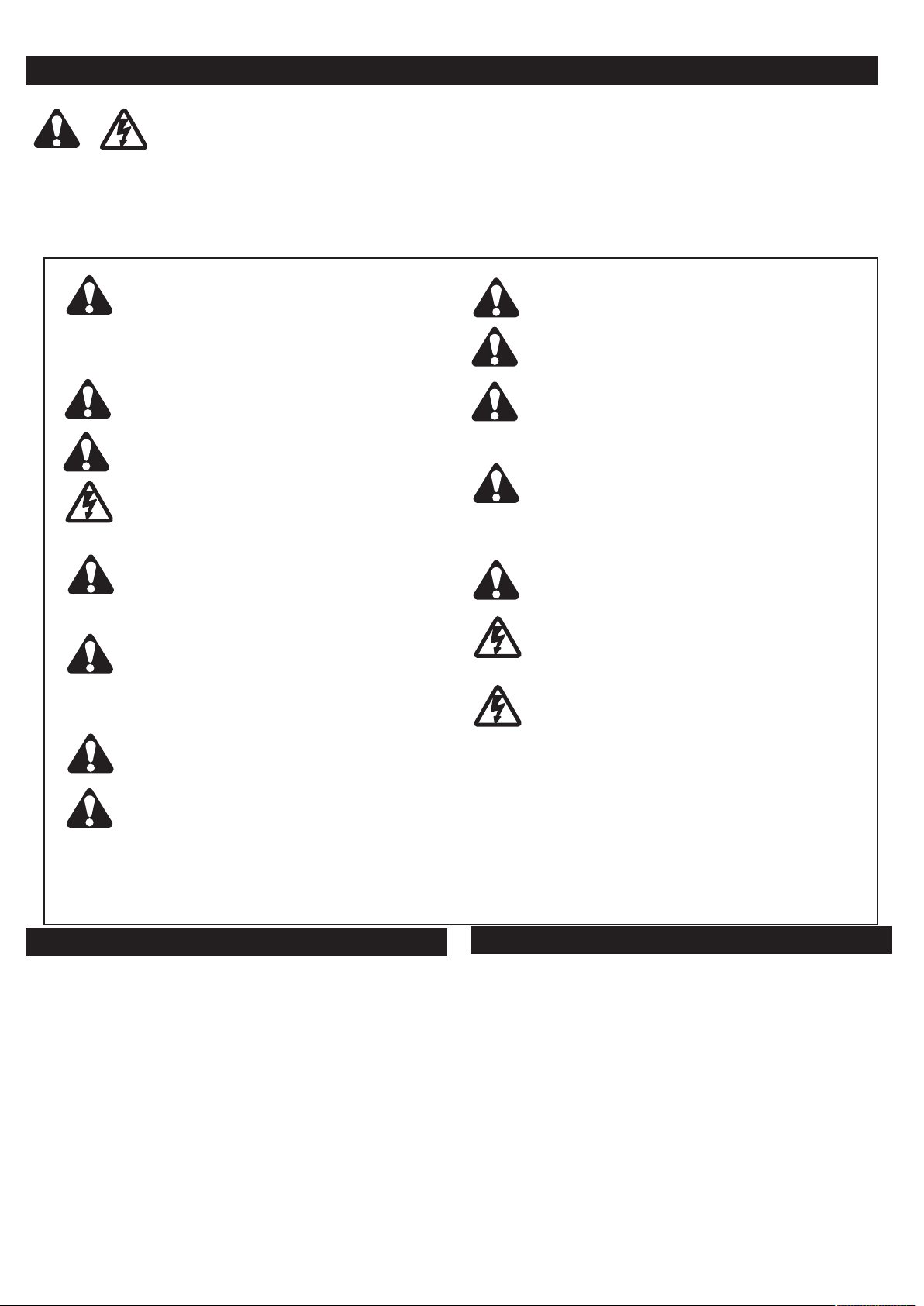
Start by Reading These Important Safety Rules
These safety alert symbols mean
Read these instructions carefully.
This garage door opener is designed and tested to offer reasonable safe service provided it is installed
and operated in strict accordance with the following safety rules.
Failure to comply with the following instructions may result in serious personal injury or property dam-
age.
WARNING
– a personal safety or property damage instruction.
WARNING: If your garage has no service entrance door, Model 1702AML Outside Quick Release must be installed.
This accessory allows manual operation of the garage door from outside in case of power failure.
Keep garage door balanced.
ing doors must be repaired. Garage doors, door
springs, cables, pulleys, brackets and their
hardware are under extreme tension and can
cause serious personal injury.
to loosen, move or adjust them.
garage door service.
Do not wear rings, watches or loose clothing
while installing or servicing a garage door
opener.
To avoid serious personal injury from entangle-
ment,
garage door
Installation and wiring must be in compliance
with your local building and electrical codes.
remove all ropes connected to the
before installing the door opener.
This is a class 2 double insulated product,
connection to earth is not required or provided.
Lightweight doors of fiberglass, aluminum
or steel must be substantially reinforced to
avoid door damage.
check with your garage door manufacturer for
an opener installation reinforcement kit.
The best solution is to
The safety reverse system test is very
important.
contact with a 40mm obstacle placed on the
floor. Failure to properly adjust the opener may
result in serious personal injury from a closing
garage door.
Your garage door
Repeat the test once a month
and make any needed adjustments.
This unit should not be installed in a damp
or wet space.
Sticking or bind-
Do not attempt
Call for
MUST
reverse on
Fasten the child warning label adjacent to the
lighted door control button as a reminder of safe
operating procedures.
Disengage all existing garage door locks
avoid damage to garage door.
Any door control buttons (if installed)
MUST be
to
located where the garage door is visible, but
out of the reach of children. Do not allow
children to operate push button(s) or remote
control(s). Serious personal injury from a
closing garage door may result from misuse
of the opener
.
Activate opener ONLY when the door is in
full view, free of obstructions and opener is
properly adjusted. No one should enter or
leave the garage while the door is in motion.
Do not allow children to play near the door.
Use manual release only to disengage the trolley and, if possible, ONLY when the door is
closed.
Do not use the red handle to pull the
door open or closed.
Disconnect electric power to the garage
door opener before making repairs or
removing covers.
This product is provided with a transformer and
power supply cord of special design which,
damaged, MUST be replaced by a transformer from your local Chamberlain distributor and fitted by a specialist
.
SAVE THESE INSTRUCTIONS
if
Door must not extend over a public byway
during operation.
Table of Contents Page llustration(s)
Safety Rules 3
Before You Begin 3
Door Types 41
Tools Required 42
Hardware Provided 43
Completed Installation 54
Assembly 5-7 5 - 10
Installation 7-10 11 - 17
Adjustment 11 18 - 20
Test the Safety Reverse System 11 19
I
Table of Contents Page llustration(s)
Install The Protector System™
(Optional) 11
Program Remote 11 20
Replace Light Bulb 12 21
Operation Of Your Opener 13
Care Of Your Opener 14
Maintenance Of Your Opener 14
Troubleshooting 14
Wiring the Multi-Function Door
Control Panel and the Lighted
Door Control Button (Optional) 12 22
Accessories 12 23
Replacement Parts 13 24
Specifications 14
3
Page 4
3
4
3
5
2
6
7
8
9
10
11
12
1
12
16
(4x)
18
13
17
1
5
Before You Begin
1
A
B
2
1
2
1. Look at the wall or ceiling above the garage door. The header bracket
ports.
2. Do you have a finished ceiling in your garage? If so, a support bracket and additional fastening hardware (not supplied) may be required.
3. Do you have an access door in addition to the garage door? If not, Model 1702AML Outside Quick Release
Accessory is required.
MUST
be securely fastened to structural sup-
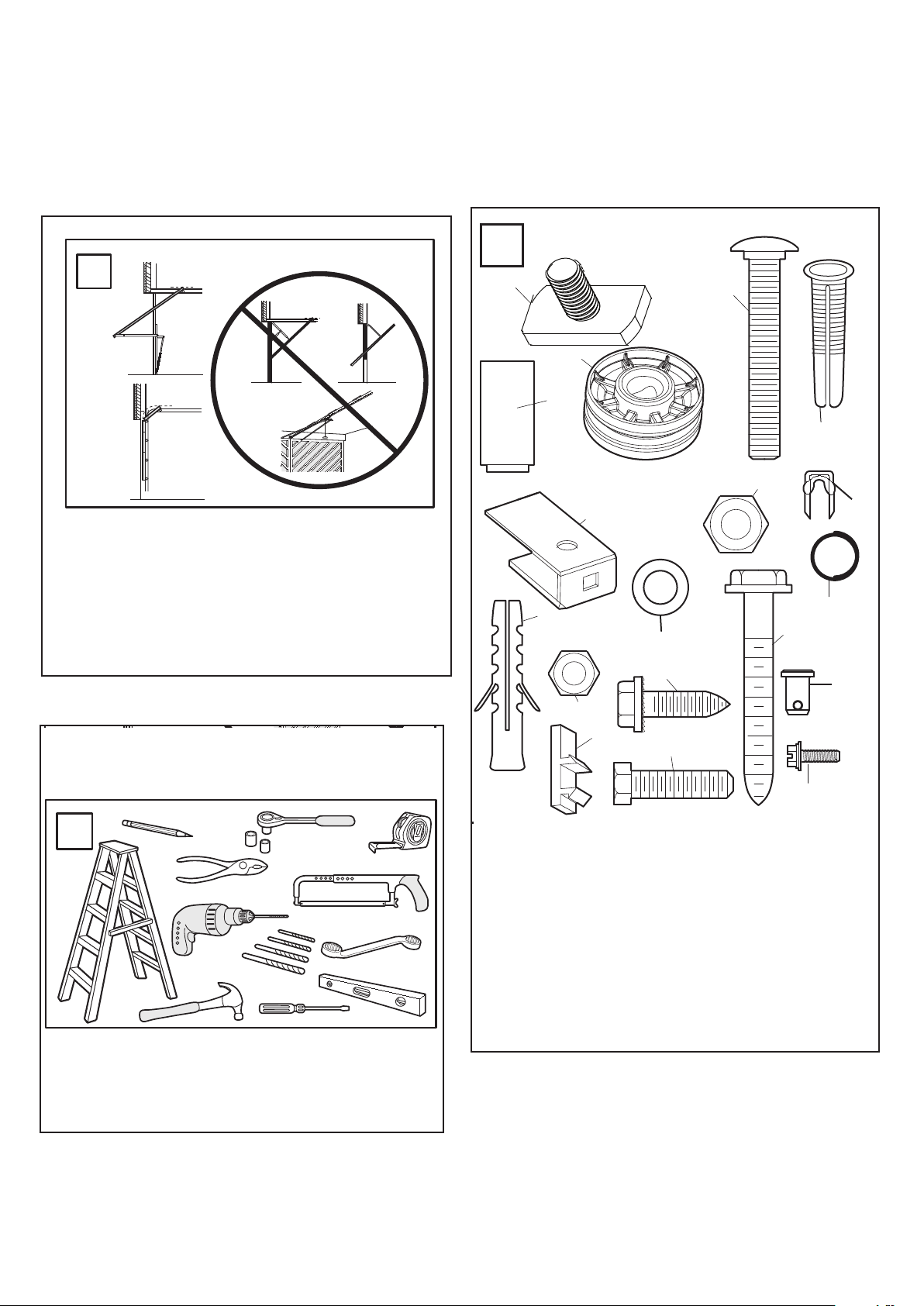
Door Types
A. One-Piece Door with Horizontal Track Only
B. Sectional Door with Curved Track
NOTE: Unit will not work with One-Piece Doors with
Horizontal and Vertical Tracks, Double-Wing Doors, or
Canopy Doors.
Tools Required for Installation
19
Hardware Provided
ASSEMBLY HARDWARE
1. Square Head Screw 6mm (2)
2. 8mm Carriage Bolt (1)
3. Cable Pulley (1)
4. Pin (1)
5. 8mm Lock Nut (1)
6. Pulley Bracket (1)
7. 6mm Nut (6)
8. Concrete Anchor (4)
9. 6mm Lag Bolt (4)
.
10. 6mm Self-Threading screw (4)
11. 6mm Hex Bolt (4)
12. Wire Clips (3)
13. Hex Screws (2)
14. C-Rail Bracket (see image 9)
15. Clevis Pin (2)
16. Ring Fastener (2)
17. Flat Washer (1)
18 Anchor (2)
19. Insulated Staples (10)
4
Page 5
1
2
3
4
5
6
7
8
9
10
11
12
NOTICE
9
4
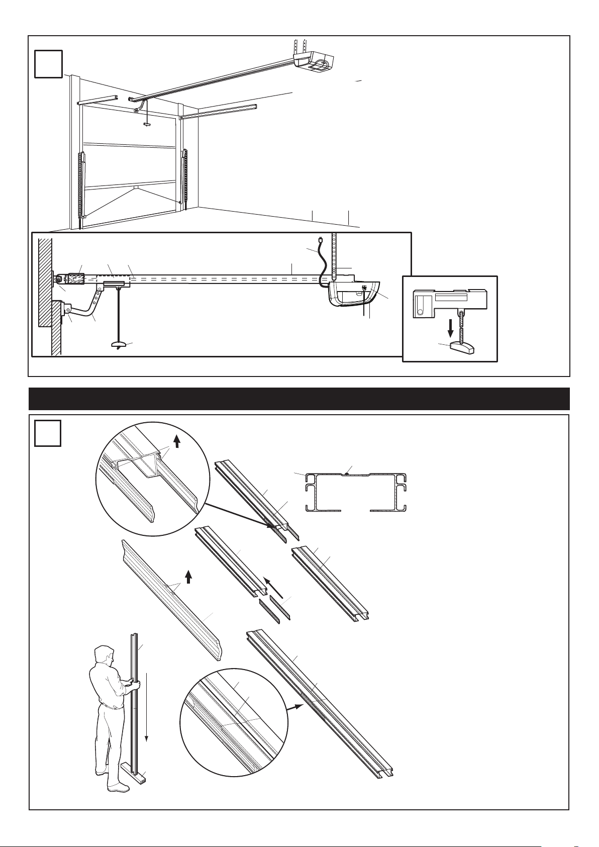
Completed Installation
1
1
1
4
4
1
5
5
4
6
2
2
4
5
4
3
3
As you proceed with the assembly, installation and
adjustment procedures in this manual, you may find
it helpful to refer back to this illustration of a completed installation.
(1) Cable Pulley Bracket
(2) Trolley
(3) Chain/Cable Assembly
(4) Rail
(5) Hanging Bracket
(6) Power Cord
(7) Opener
(8) Light Lens
(9) Manual Release
Rope & Handle
(10) Door Arm
(11) Door Bracket
(12) Header Bracket
5
Assembly
Assemble Rail
Place Rail pieces (1) on a flat surface
for assembly. Take special note of the
raised line on the Rail pieces (4) these
lines MUST line up in order for the Rail
to fit together properly. All three Rail
sections are interchangeable. Slide
Rail Braces (2) into slots on the sides of
Rail. Make sure small tabs on Rail
Braces (3) are up against top lip of Rail.
Connect Rail by sliding other end of
braces into next Rail. Be sure the
raised lines that run down Rail sections
(4) line up. Tap Rail assembly (5) on a
piece of wood (6) until Rail sections are
flush. Repeat for final Rail section.
5
Page 6

1
2
5
4
4
3
1
2
5
1
2
4
3
6
6
1
2
3
2
4
1
2
1
3
4
4
Assemble Cable Pulley Bracket
Insert Carriage Bolt (1) though square hole in Cable Pulley Bracket (4). Remove Chain/Cable assembly (3) from
carton. Wrap Cable around Cable Pulley (2) and insert Pulley into Bracket (
assembled in position shown).
Slide pin (5) through holes in Cable Pulley Bracket and Cable Pulley.
Magnet (6) MUST be installed in the position shown.
NOTE: Make sure the Bracket is
NOTE: Trolley with
7
Insert Chain/Cable into Rail
Slide Cable Pulley Bracket (1) into Rail assembly (3), be
sure to insert Cable Pulley Bracket as shown. Push Cable
Pulley Bracket toward front of Rail and slide Inner Trolley
(2) into Rail assembly. Magnet (4) MUST be installed in
position shown or unit will not function properly.
8
Attach Trolley to Rail
Turn Rail assembly over. Slide Outer Trolley (1) into Rail
assembly (2), be sure the end with Door Arm Hole (3) is
heading in direction of door (4). Slide Outer Trolley down
Rail until it engages with Inner Trolley.
6
Page 7

1
2
2
1
9
5
2
2
3
3
5
4
4
4
6
6
6
1
2
Attach Rail to Unit
Turn Rail assembly over. Wrap Chain around Drive Sprocket (1). Slide Rail assembly (2) toward unit and into slots
on top of unit. Attach C-Bracket (3) on the rail and secure with screws (4) as shown Push Cable Pulley Bracket
forward making Chain tight on sprocket. Chain MUST engage teeth on Drive Sprocket.
10
Attach Header Bracket
Turn Rail and Unit assembly over. Slide Cable Pulley Bracket (2) toward front end of Rail (3). Be careful Chain does not
come off Drive Sprocket on unit or become twisted. Slide Carriage Bolt (5) into Header Bracket (1). Secure with Lock
Nut (4) behind wash (6). Tighten Nut until Chain does not droop below rail. Do NOT over tighten.
INSTALLATION SECTION
Wear protective goggles when working overhead to
protect your eyes from injury.Disengage all existing
garage door locks to avoid damage to garage door. To
avoid serious personal injury from entanglement,
remove all ropes connected to garage door before
installing opener. Installation of this product shall
comply with ZH1/494, VDE 0700 Part 238, and VDE
0700 Part 1. It is recommended that the opener be
installed 2.1m (7 feet) or more above the floor where
space permits.
11
Find Center of Garage
Mark center of door (1). Extend line onto ceiling
(2).
7
Page 8

3
2
1
1
4
50mm
50mm
2
50mm
(2")
1
4
B
A
3
6
150mm
(6")
1
2
5
5
5
5
5
1
2
2
1
1
2
12
Install the Header Bracket
NOTE: Refer to vertical center and horizontal
lines created in step 12 for proper placement of
header bracket.
A. Wall Mount: Center the header bracket (1) on
the vertical center line (2) with the bottom edge
of the header bracket on the horizontal line (4)
(with the arrow pointing toward the ceiling).
Mark all of the header bracket holes (5). Drill
4.5 mm (3/16") pilot holes and fasten the
header bracket with wood screws (3).
B. Ceiling Mount: Extend vertical center line (2)
onto the ceiling. Center the header bracket (1)
on the vertical mark no more than 150 mm (6")
from the wall. Make sure the arrow is pointing
toward the opener. Mark all of the header
bracket holes (5). Drill 4.5 mm (3/16") pilot
holes and fasten the header bracket with wood
screws (3). For concrete ceiling mount, use
concrete anchors (6) provided.
Clearance between highest point of travel and
Rail should not exceed 50mm and can be zero
when clearance between door and ceiling is
only 30mm.
13
Attach Rail to Header Bracket
Position the opener on the floor below the mounting
bracket using some packaging material to protect the
unitʼs cover. Raise the rail the holes in the header sleeve
and the holes of the header to align bracket. Use the
clevis pin (1) provided to join the two pieces, then insert
the fastening ring (2) to secure in place.
Note: To enable the rail to clear sectional door springs,
it may be necessary to lift the opener onto a temporary
support. The opener must secured in place by means of
a support or by being held by another person.
8
Page 9

1
1
5
3
4
2
5
5
2
2
3
3
A
B
C
B
5
4
4
A
1
3
4
2
3
2
4
4
1
2
14
B
1
4
A
1
2
4
Fasten Door Bracket
A. Place Door Bracket (2) on the top of the door (3) and center over Vertical Center Line (1). Mark the two rear top
holes. Drill 4mm holes.
B. Mark the two top front holes. Drill 4mm holes. Fasten Door Bracket (2) to the top of the door (3) using Screws (4)
.
15
Hang Opener
Bend Hanging Brackets (1) so they are flat against ceiling. Measure distance from Header Bracket to Ceiling Mounting
Bracket Bolts. Mark length on ceiling starting at the Header Wall, along this point is where the unit will be mounted. Lift
door to full open position, rest opener on door. Insert Square Head Screws (A) into Rail assembly (B) approximately
120mm from end of Rail near motor unit. Slide Hanging Brackets on to Square Head Screws and secure Brackets with
Nuts (5). In this process the Square Head Screws hook into slots on the sides of Rail by turning 90° (C). For concrete
ceilings, drill 8mm pilot holes into ceiling and insert Concrete Anchors (2). Secure Hanging Brackets to ceiling with Lag
Screws (3). For wood ceilings, drill 4mm pilot holes and secure with Lag Screws (3).
9
Page 10

A
B
1
3
1
2
3
1
4
3
2
2
3
1
1
5
1
2
3
1
3
4
5
3
16
1
4
5
8
6
7
2
9
10
3
9
Connect Door Arm to Trolley
A. Preferred Installation:
Disconnect Trolley by pulling on the red handle and slide towards door. With door closed connect Straight Door
Arm (5) to Trolley (4) with Bolt (3), secure with Nut (1). Connect Curved Door Arm (2) to Door Bracket with Bolt (3)
Secure with Nut (1). Align Straight and Curved Door Arms with a 2 hole overlap connect with Bolt (3), secure with
Nut (1), If Straight Door Arm (5) is too long, cut the end of the Door Arm.
B. Where extra travel distance is required:
With door closed connect Curved Door Arm (2) to Door Bracket with Bolt (3), secure with Nut (1). Lift Curved Door
Arm (2) to meet Trolley, connect door arm to Trolley with Bolt (3), secure with Nut (1).
Connect Electric Power
To avoid installation difficulties, do not run the garage door opener until instructed to do so.
Plug the opener into electric outlets as specified by local wiring codes. The opener light will turn on when power is
connected and remain on for 2-1/2 minutes.
17
Attach Limit Switches
NOTE: The limits must be installed as shown. If installed incorrectly the unit will not function properly.
Close garage door by hand. Determine the position of the Close Limit Switch (1) (Long wire) by aligning the center of
trolley and the center of the Limit Switch. The Limit Switches are actuated by a magnet in the Inner Trolley.
Insert bottom tab (5) of Limit Switch (1) into bottom lip of Rail (7). Insert top tab (4) under top lip of Rail (6). Lift limit
assembly against top lip of Rail and tighten screw (8) to secure Close Limit Switch.
Open garage door by hand to the full open position. Pull red handle to open door past Inner Trolley. Determine the
position of the Open Limit Switch (3) (Short Wire) by aligning the center of the Trolley and the center of the Limit Switch.
Insert bottom tab (5) of Limit Switch (1) into bottom lip of rail (7). Insert top tab (4) under top lip of rail (6). Lift limit
assembly against top lip of rail and tighten screw (8) to secure Open Limit Switch.
Insert wires for Limit Switch (9) into top channel of Rail (10). Secure wires with wire clip. the wires must be secured so
they do not interfere with the travel of the Trolley. Activate remote, the opener will operate and reconnect to the door
automatically.
Run opener 2 full travel cycles. If the door reverses in mid travel go to Setting the Force Section. Adjust Limit Switches
as necessary to fully open and close the door without reversing.
10
Page 11

1
2
1
18
1.
2.
3.
1
2
1
2
Setting the Force
The Force is programmed to operate most doors, however,
if Limits are not able to be set, or the door reverses during
normal operation follow this procedure: Locate the Program
Button (1) on the left side panel of unit (2). Push the
Program Button twice to enter unit into Auto-Force
Adjustment Mode. The green LED will flash slowly. Activate
unit with remote and run the unit to the Open Limit. Activate
unit again to run the unit to the Closed Limit. The door must
travel through a complete cycle up and down in order for the
Force to be set properly. If the unit stops before it reaches
the Open or Close Limit repeat the process. The green LED
will stop flashing when the Force has been learned
19
Test the Safety Reverse System
The safety reverse system test is important. Garage
door must reverse on contact with a 40mm obstacle
laid flat on the floor. Failure to properly adjust opener
may result in serious personal injury from a closing
garage door. Repeat test once a month and adjust as
needed.
.
Procedure: Place a 40mm obstacle (1) laid flat on the
floor under the garage door. Operate the door in the
down direction. The door must reverse on the
obstruction. If the door stops on the obstruction, it is not
traveling far enough in the down direction. Move Close
Limit closer to door
When the door reverses on the 40mm obstacle, remove
the obstruction and run the opener through a complete
travel cycle. Door must not reverse in closed position. If
it does, adjust Limit and repeat safety reverse test.
Place 20kg at the center of the door and ensure that the
door will not move up more than 500mm.
SAVE THESE INSTRUCTIONS
Install Protector System™(Optional) – (See accessories)
After opener has been installed and adjusted, The Protector System™ accessory can be installed. Instructions are
included with this optional device.
The Protector System™ provides an additional measure of safety against a small child being caught under a
garage door.
It uses an invisible beam which, when broken by an obstruction, causes a closing door to open and prevents an open door
from closing and is
strongly recommended for homeowners with young children.
Program Remotes
20
Activate the opener only when door is in full view, free
of obstruction and properly adjusted. No one should
enter or leave garage while door is in motion.
Your garage door opener receiver and Remote Control
Transmitter are set to a matching code. If you purchase
additional Remote Controls, the garage door opener must
be programmed to accept the new Remote code.
To program receiver to match additional Remote
Control codes:
1.Press and release the program button on the side of the
unit (1). The green LED will glow steadily for 30 seconds.
2.Within 30 seconds press and hold the button on the
hand-held Remote (2).
3.Release the button when the motor unit light blinks. It
has learned the code. If the light bulb is not installed, two
clicks will be heard.
To erase all codes from motor unit memory or to
deactivate any unwanted Remote, first erase all codes:
Press and hold the program button (1) on motor unit until
the learn indicator light goes out (approximately 6
seconds). All previous codes are now erased. Reprogram
each Remote or Keyless Entry you wish to use.
11
Page 12

1
2
21
LOCK
LIGHT
8
8
4
2
3
1
WHT
2
RED
1
1
2
1
RED
WHT
LOCK
LIGHT
1
2
7
3
5
6
8
9
10
4
LOCK
LIGHT
8
9
7
3
2
5
4
LOCK
LIGHT
6
1
22
Replace Light Bulb
Replace light bulb (1) with a 21
watt ma-mum light bulb. Insert
bulb into socket (2) as shown.
The light will turn on and remain
lit for 2 1/2 minutes when power
is connected. After 2 1/2 minutes
it will turn off.
Wiring the Backlit Door Control Button or the (optional) Multi-Function Door Control Panel
Locate any Wall Mounted Door Control where the garage door is visible, away from door and door hardware, at a
minimum height of 1.5m. fasten the child warning label on the wall near the Door Control.
There are 2 screw terminals (1) on the back of the Door Control (2). Strip about 6mm of insulation from bell wire (4).
Separate wires enough to connect the white/red wire to terminal screw 1 and the white wire to terminal screw (1).
Backlit Door Control Button: Fasten to an inside garage wall with sheet metal screws (3) provided with Backlit Push
Button. Drill 4mm holes and use anchors (6) if installing into drywall or concrete. A convenient place is beside the service
door and out of reach of children.
Multifunction Door Control (optional): Insert a small flat head screwdriver into the top of the Wall Control (10), gently
pry the cover off. Fasten to an inside garage wall with sheet metal screws (8) as follows:
• Install bottom screw, allowing 3mm to protrude from the wall.
• Position bottom of door control over screw head and adjust for snug fit.
• Install top screw with care to avoid cracking plastic housing.
• Replace cover by inserting bottom tabs (9) and snapping into place. To remove cover after mounting, gently pry at top
with paper clip or small flat head screwdriver.
Run the bell wire up the wall and across the ceiling to the garage door opener. Use insulated staples (5) to secure wire.
The opener Quick-Connect Terminals (7) are located in the recess next to the learn button on the left side panel. Insert bell
wire into holes in the Quick Connect Terminals as follows: Red/White to Red and White to White.
Do not over tighten.
23
Accessories
(1) Model 84330AML Single Function Remote Control
(2) Model 84335AML 3-Function Mini Remote Control
(3) Model 84333AML 3- Function Remote Control
(4) Model 770AML The Protector System
(5) Model 8747AML Wireless Keyless Entry Keypad
(6) Model 845AML Multi-Function Door Control Panel
(7) Model 75AML Backlit Door Control Button
(8) Model 760AML Outside Keylock
(9) Model 1702AML Outside Quick Release
12
Page 13

41A5674
41A5643
41A5644
41A5675
41A5676
1
2
3
5
6
7
4
012B0905
012B0906
012C0908
012C0788
8
24
41A5674-2
Replacement Parts
(1) 41A5644 Trolley with Chain/Cable Assy.
(2) 41A5674-2 Head Only
(3) 41A5643 Hardware Bag
(4) 012B0905 Door Bracket
012B0906 Door bracket
(5) 012C0788 Header Bracket
(6) 012C0908 Rail end piece
(7) 41A5675 Rail Hardware
(8) 41A5676 Rail Sections
Operation Of Your Opener
Your opener can be activated by any of the following devices:
• The Remote Control Transmitter. Hold the push button down until the door starts to move.
• The Backlit Door Control Button (if you have installed this accessory). Hold the button down until door starts to move.
• The Outside Keylock or Keyless Entry System (if you have installed either of these accessories).
Opening the Door Manually:
Door should be fully closed if possible. Weak or broken springs could allow an open door to fall rapidly. Property
damage or serious personal injury could result.
The door can be opened manually by pulling the release handle down. To reconnect the door, activate the unit.
Do not use the manual release handle to pull the door open
or closed.
When the Opener is Activated by Remote Control or Door Control Button:
1. If fully open, the door will close.
2. If closed, the door will open.
3. If opening or closing, the door will stop.
4. If partially open, the door will move in the opposite direction of last travel.
5. If an obstruction is encountered while closing, the door will reverse to the open position.
6. If an obstruction is encountered while opening, the door will reverse for 1 second.
7. The optional Protector System™ uses an invisible beam which, when broken by an obstruction, causes a closing
door to open and prevents an open door from closing. It is STRONGLY RECOMMENDED for homeowners with
young children.
Allow a 15 minute cooling period after 5 continuous operations of the opener.
The opener light will turn on: 1. when opener is initially plugged in;
2. when the power is interrupted; 3. when the opener is activated.
The light turns off automatically after 2-1/2 minutes. Bulb size is
21 Watts maximum.
13
Page 14

TROUBLE SHOOTING
1. Opener doesn’t operate from remote:
• Does the opener have electric power? Plug lamp into outlet. If it
doesn’t light, check the fuse box or the circuit breaker. (Some outlets
are controlled by a wall switch.)
• Have you disengaged all door locks? Review installation instruction
warning on page 1.
• Try a new battery.
• If you have two or more remotes and only one operates, review
receiver programming procedures in Step 21.
• Is there a build-up of ice or snow under door? The door may be
frozen to ground. Remove any obstruction.
• The garage door spring may be broken. Have it professionally
replaced.
2. Remote has short range:
• Is battery installed? Try a new one.
• Change the location of the remote control in the car.
• The metal garage door, foil-backed insulation or metal siding will
reduce the transmission range.
3. Door reverses for no apparent reason and opener lights don’t
blink:
• Is something obstruction the door? Pull Manual Release Handle.
Operate door manually. If it is unbalance or binding, call for professional garage door service.
• Reprogram the Force.
• Clear any ice or snow from garage floor area where garage door
closes.
• If door reverses in fully closed position, adjust the Close Limit.
Repeat safety reverse test after adjustment is complete.
The need for occasional adjustment of the Limit positions is normal.
Weather conditions in particular can affect door travel.
4. Door reverses for no apparent reason and door control button
light blinks for 5 seconds after reversing:
• Check The Protector System™ (if you have installed this accessory).
if the light is blinking, correct alignment.
TROUBLE SHOOTING CONTINUED
5. The garage door opens and closes by itself:
• (Keypad or Code Switch transmitters only) Is there a neighbor with a
garage door opener using the same code? Change your code.
• Make sure remote push button is not stuck in ON position.
6. Door does not close completely:
Adjust the Close Limit.
Repeat safety reverse test after any adjustment of door arm length,
or Close Limit.
7. Door opens but won’t close:
• Check The Protector System™ (if you have installed this accessory).
If the light is blinking, correct alignment.
Repeat the safety reverse test after the adjustment is complete.
8. Opener light does not turn on:
Replace light bulb (21 Watts maximum).
9. Opener light does not turn off:
Defective logic board.
10. Opener motor hums briefly, then won’t work:
• Garage door springs are broken. Close door and use Manual
Release Rope and handle to disconnect Trolley. Open and close door
manually. A properly balanced door will stay in any point of travel
while being supported entirely by its springs. If it does not, call for a
professional garage door service to correct the problem.
• If problem occurs on first operation at opener, door may be locked.
Disable door lock.
11. Opener won’t activate due to power failure:
• Pull Manual Release Handle to disconnect Trolley. Door can be
opened and closed manually. The next time opener is activated, the
Trolley will reconnect.
• The Outside Quick Release accessory 1702AML (if fitted) disconnects the Trolley from outside the garage in case of power failure.
Specifications
Input Voltage . . . . . . . . . . . .230 VAC 50/60 Hz
Max. Pull force . . . . . . . . . .600N
Rated Power Input . . . . . . .85 Watts
Rated Load . . . . . . . . . . . . .3.0 Nm
Standby Power . . . . . . . . . .9 Watts
Max. Door Weight . . . . . . . .60kg
Motor
Type . . . . . . . . . . . . . . . . . .63:1 Worm Gear Reduction
Volts . . . . . . . . . . . . . . . . . .24VDC
Drive Mechanism
Length of Travel . . . . . . . . .2.3M
Travel Rate . . . . . . . . . . . . .8cm/sec
Lamp . . . . . . . . . . . . . . . . . .24V 21 Watts
Safety
Electronic . . . . . . . . . . . . . .Auto-Force Adjustment
Electrical . . . . . . . . . . . . . . .Thermal Fuse in Transformer
Limit Adjustment . . . . . . . . .Manual
Dimension
Length (Overall) . . . . . . . . .2.75m
Headroom Required . . . . . .30mm
Hanging Weight . . . . . . . . . .9kg
Receiver Code Registers
Rolling Code . . . . . . . . . . . .8
Keypad . . . . . . . . . . . . . . . .1
Operating Frequency . . . . .433.92MHz
Care Of Your Opener
When properly installed, opener will provide high
performance with a minimum of maintenance. The
opener does not require additional lubrication.
Limit and Force Adjustments: These adjustments must
be checked and properly set when opener is installed.
Only a screwdriver is required to adjust the limits. Weather
conditions may cause some minor changes in the door
operation, requiring some re-adjustments, particularly
during the first year of operation. Refer to the Limit and
Force Adjustments on page 2. Follow the instructions
carefully and repeat the safety reverse test after any
adjustment.
Remote Control Transmitter: Additional Remotes can
be purchased at any time for use in all vehicles using
garage. Refer to Accessories.The receiver must be
programmed to operate with any new Remote.
Remote Control Battery: The lithium batteries should
produce power for up to 5 years. If transmission range
decreases, replace battery.
To Change Battery: Insert batteries positive side up. To
replace cover, snap shut along both sides. Do not dispose
of the old battery with household waste. Take batteries to
a proper disposal center.
Maintaining Your Opener
• Apply grease to rail and trolley
• Oil door rollers, bearings and hinges
• DO NOT lubricate the opener itself
• DO NOT APPLY grease to the door tracks
14
Page 15

CHAMBERLAIN 1 YEAR LIMITED WARRANTY
Motorlift ML500
Garage Door Operator
Chamberlain Australia Pty Limited / Chamberlain New Zealand Limited
(Seller) warrants to the original purchaser of the Motorlift ML500
Garage Door Operator (Unit) that it is free from defects in material
and/or workmanship for a period of 12 months from the date of first
purchase from the Seller.
Please retain your proof-of-purchase in the unlikely event you require
warranty service.
If, during the limited warranty period, the Unit fails due to defects in
materials or workmanship Chamberlain will, provided the defective part
or Unit is returned freight and insurance prepaid and well packaged to
the nearest Chamberlain office or authorised installer, undertake to
repair or, at its option, replace any defective part or Unit and return it to
the Buyer at no cost. Repairs and replacement parts are warranted for
the remaining portion of the original warranty period.
Limited warranty on motor
Chamberlain will furnish a replacement motor free of charge, if it is
found to be defective. Labour costs may apply.
Where the Unit has been installed by an authorised installer,
Chamberlain will furnish replacement parts free of charge through the
authorised installer. A service fee for on-site service may apply.
In-warranty service
During the warranty period, if the product appears as though it may be
defective, call our toll free service before removal of the unit. A
Chamberlain technician will diagnose the problem and promptly supply
you with the parts for “do-it-yourself” repairs, or provide you with shipping instructions for a factory repair or replacement. If an authorised
installer installed your unit you must call them for prompt on-site service.
Liability – New Zealand only
Except as set out in the Fair Trading Act 1986 and the
Consumer Guarantees Act 1993:
(a) all other guarantees, warranties and representations
in relation to the Unit or its supply are excluded to the extent
that the Seller can lawfully exclude them; and
(b) under no circumstances shall the Seller be liable for
consequential, incidental or special damages arising in connection with the use, or inability to use, the Unit, other than
those which were reasonably foreseeable as liable to result
from the failure.
NOTE: We request that you attach your sales docket or
invoice to this manual to enable you to establish the date of
purchase in the unlikely event of a service call being made.
Chamberlain reserves the right to change the design and
specification without prior notification. Some features or
accessories may not be available in certain markets or areas.
Please check with your distributor.
New Zealand Ltd
Phone toll free 0800 MERLIN
Fax toll free 0800 653 663
www.motorlift.co.nz
If our service centre determines that a warranty claim has been made
in respect of a failure or defect arising under out of any exclusion set
out below, we may charge you a fee to repair and/or return the Unit to
you.
Exclusions
This warranty does not cover any failure of the Unit due to:
1. non-compliance with the instructions regarding installation,
operation, maintenance and testing of the Unit or of any product with
which the Unit is used.
2. any attempt to repair, dismantle, reinstall or move the
Product to another location once the Product is installed by any person
other than an authorised installer.
3. tampering, neglect, abuse, wear and tear, accident, electrical
storm, excessive use or conditions other than normal domestic use.
This warranty does not cover any problems with, or relating to, the
garage door or garage door hardware, including but not limited to the
door springs, door rollers, door alignment or hinges, any problems
caused by electrical faults, replacement of batteries or light bulbs or
labour charges for reinstalling a repaired or replaced Units.
Liability – Australia only
Under no circumstances shall the Seller be liable for consequential,
incidental or special damages arising in connection with the use, or
inability to use, the Unit. In no event shall the Seller's liability for damages or injury arising from breach of law or contract or for negligence,
exceed the cost of repairing or replacing the Unit or refunding the purchase price of the Unit.
Under Division 2 Part V of the Trade Practices Act, 1974, certain warranties and conditions (Implied Terms) are implied into contracts for the
supply of goods or services if the goods or services are of a kind ordinarily acquired for personal, domestic or household use or consumption. Liability for breach of those Implied Terms cannot be excluded or
limited and the limitations and exclusions above do not apply to the
Implied Terms.
Except for the Implied Terms and the warranties set out above, the
Seller excludes all warranties and conditions implied by statute, at law,
in fact or otherwise.
:
Australia Pty Ltd
Phone toll free 1800 638 234
Fax toll free 1800 888 121
www.motorlift.com.au
15
Page 16

NOTES:
114A3449 ANZ
 Loading...