

Page 1
IPAC Server
IPAC Server
IPAC Server
Administrator’s
Manual
Page 2

Page 3

IPAC Server Administrator’s Manual Page 2 of 334
Table of Contents!
1. Getting Started ................................................................................................ 10
System Overview: IPAC Server™ and the IPAC SYSTEM ........................................ 11
IPAC Server™ .................................................................................................. 13
IPAC SYSTEM control panels in Client Mode .......................................................... 14
Browser Requirements ...................................................................................... 15
Main Features of the IPAC Server™ ..................................................................... 16
2. Network Environment ....................................................................................... 17
Networking Requirements IPAC Server™ with multiple IPAC SYSTEM panels on a single
LAN ................................................................................................................ 18
Adding an IPAC SYSTEM to the IPAC Server™ ...................................................... 21
Adding an IPAC SYSTEM panel using manual handshake mode ............................... 22
Accessing IPAC Server™ .................................................................................... 23
3. Home ............................................................................................................. 25
4. Status ............................................................................................................. 26
Browsing the Dashboard .................................................................................... 27
Managing the Dashboard ................................................................................... 30
Using Display Filters ......................................................................................... 39
Live Map/Floorplan ........................................................................................... 41
5. Accounts ......................................................................................................... 42
What is an Account? ......................................................................................... 43
Defining the Initial System Account Administrator ................................................. 44
Viewing Account Details .................................................................................... 48
Creating Tenant Accounts .................................................................................. 50
Managing Account Contact Information ............................................................... 53
6. Administrators and Administrator Roles ............................................................... 54
Administrator Roles .......................................................................................... 58
Definitions of Permissions .................................................................................. 59
7. Schedules and Holidays ..................................................................................... 64
What are Schedules? ........................................................................................ 65
What are Holidays? ........................................................................................... 66
Browsing the Schedules List ............................................................................... 67
Viewing Schedule Details ................................................................................... 68
Creating a Schedule .......................................................................................... 69
Managing Schedules ......................................................................................... 72
Browsing the Holidays List ................................................................................. 74
Creating a Holiday ............................................................................................ 75
Managing Holidays ............................................................................................ 76
8. Devices ........................................................................................................... 77
Managing Multiple Control Panels ........................................................................ 79
Programmable Devices ...................................................................................... 80
Page 4

IPAC Server Administrator’s Manual Page 3 of 334
3
Special Options for Devices: Floors and Elevators ................................................. 81
Special Options for Devices: Cameras ................................................................. 84
Special Options for Devices: DVRs ...................................................................... 87
Special Options for Devices: Muster Points ........................................................... 90
Special Options for Devices: Keypad Commands ................................................... 92
Special Options for Devices: Guard Tour .............................................................. 95
Special Options for Devices: Salto Routers and Salto Door Locks ............................. 97
Special Options for Devices: DEDs (Data Entry Devices) ...................................... 101
Viewing Video ................................................................................................ 104
Viewing Panel and Board Details ....................................................................... 107
Update and/or Configure a Control Panel ........................................................... 109
Control Panel Options ...................................................................................... 110
Adding Control Boards ..................................................................................... 113
Managing Control Boards ................................................................................. 114
Browsing the Devices List ................................................................................ 118
Viewing Device Details .................................................................................... 119
Creating Devices ............................................................................................ 122
Device Profiles ............................................................................................... 123
Live Status .................................................................................................... 125
Managing Devices ........................................................................................... 127
9. Maps/Floorplans ............................................................................................. 134
Maps/Floorplans Definitions ............................................................................. 135
Browsing Maps/Floorplans ............................................................................... 136
Managing Maps/Floorplans ............................................................................... 137
Live Map ....................................................................................................... 143
10. Antipassback ................................................................................................. 145
Antipassback Zones ........................................................................................ 146
Antipassback Definitions .................................................................................. 147
Hard Antipassback .......................................................................................... 147
Soft Antipassback Reset Interval ...................................................................... 147
Antipassback Immunity ................................................................................... 147
Important Antipassback Considerations ............................................................. 148
Managing Antipassback Controls ....................................................................... 149
11. Cards ............................................................................................................ 154
What is a Card? .............................................................................................. 155
Browsing the Cards List ................................................................................... 156
Adding Cards ................................................................................................. 158
Managing Card Formats ................................................................................... 161
Managing Card Assignments ............................................................................ 168
Managing Cards ............................................................................................. 169
12. Badging ........................................................................................................ 171
What are Badges? .......................................................................................... 172
Badge Templates ............................................................................................ 173
13. Users and Groups ........................................................................................... 182
What are Users, User Aliases, and Groups? ........................................................ 183
Page 5

IPAC Server Administrator’s Manual Page 4 of 334
4
Browsing the Groups List ................................................................................. 184
Viewing Group Details ..................................................................................... 185
Creating a Group ............................................................................................ 187
Creating a Group Enabled Schedule .................................................................. 189
Managing Groups ........................................................................................... 191
Browsing the Users List ................................................................................... 193
Viewing User Details ....................................................................................... 195
Creating a User .............................................................................................. 197
Managing Users .............................................................................................. 202
Managing Custom Fields .................................................................................. 204
14. Activity ......................................................................................................... 207
Browsing the System Activity Log ..................................................................... 208
Index of Events .............................................................................................. 210
Generating an Activity Report........................................................................... 213
Exporting the Activity Log ................................................................................ 215
15. Reporting ...................................................................................................... 216
What is Reporting? ......................................................................................... 217
Browsing the Reports List ................................................................................ 218
Creating a New Report .................................................................................... 219
Managing Reports ........................................................................................... 221
Browsing the Scheduled Reports List ................................................................. 224
Creating a New Scheduled Report ..................................................................... 225
Managing Scheduled Reports ........................................................................... 227
Running a Muster Report ................................................................................. 229
Browsing the Administrative Journal .................................................................. 230
16. Threat Levels ................................................................................................. 231
Who Can Change Threat Levels? ....................................................................... 232
Threat Level Influence ..................................................................................... 233
Threat Level Configuration ............................................................................... 235
Threat Level Severity ...................................................................................... 238
Editing Permissions for Threat Levels ................................................................ 240
Editing Devices for Threat Levels ...................................................................... 241
Editing Schedules for Threat Levels ................................................................... 242
Threat Levels and Shared Devices .................................................................... 243
17. Email Notifications .......................................................................................... 245
What are Email Notifications? ........................................................................... 246
Browsing the Notifications List .......................................................................... 247
Creating Notification Rules ............................................................................... 248
Managing Notification Rules ............................................................................. 249
Sample Email Notifications ............................................................................... 250
18. System Management ...................................................................................... 251
Maintenance Mode .......................................................................................... 252
Browsing the System Status Page/Using Maintenance Mode ................................. 253
Browsing the System Logs ............................................................................... 256
Using System Tools ........................................................................................ 257
Page 6

IPAC Server Administrator’s Manual Page 5 of 334
5
Panel Comms Monitoring ................................................................................. 258
Session Management ...................................................................................... 259
Manage Running Reports ................................................................................. 260
Fetch Panel Logs ............................................................................................ 261
SNMP Agent Settings ...................................................................................... 266
Upgrading Your Firmware ................................................................................ 267
Upgrading Panels ........................................................................................... 269
License Keys .................................................................................................. 270
Manage Branding ........................................................................................... 272
FIPS Mode ..................................................................................................... 274
Importing User Data ....................................................................................... 275
Backing up Your Database ............................................................................... 278
Backup Server ............................................................................................... 280
Report Service ............................................................................................... 282
Configuring the Network .................................................................................. 283
Configuring Network Routing ............................................................................ 285
Configuring the SMTP Server ............................................................................ 286
Panel Discovery .............................................................................................. 288
Custom Server Certificates .............................................................................. 291
ES IP Pool Configuration .................................................................................. 292
19. Tenant Accounts ............................................................................................ 294
Changes in System Account Administrator Access ............................................... 295
Tenant Administrator Access ............................................................................ 300
20. Appendices .................................................................................................... 302
Appendix 1: Glossary ...................................................................................... 303
Appendix 2: Use of Report Service .................................................................... 309
Appendix 3: Salto Equipment ........................................................................... 312
Appendix 4: DVR Installation Notes ................................................................... 328
Xtralis DVR Installation Notes ........................................................................... 328
Exacq DVR Installation Notes ........................................................................... 329
Dedicated Micros DVR Installation Notes ............................................................ 330
To install the Dedicated Micros time synchronization utility: ................................. 330
To schedule the execution of the time synchronization utility: ............................... 331
Intellex DVR Installation Notes ......................................................................... 333
To install the Intellex client software: ................................................................ 333
To add your IPAC Server as a trusted site on Internet Explorer when using the Intellex
DVR: ............................................................................................................ 333
To configure the Windows NTP synchronization program for Intellex. ..................... 334
Page 7

IPAC Server Administrator’s Manual Page 6 of 334
6
Table of Figures
Figure 1. IPAC Server™ ....................................................................................... 13
Figure 2. IPAC SYSTEM Client Mode ....................................................................... 14
Figure 3. IPAC Server™ on a single LAN ................................................................. 18
Figure 4. IPAC Server™ with Multiple Panels on Multiple LANs ................................... 19
Figure 5. IPAC SYSTEM Client Mode ....................................................................... 21
Figure 6. Back of IPAC Server™ appliance .............................................................. 23
Figure 7. IPAC Server™ direct console static IP setup .............................................. 24
Figure 8. Home Page for IPAC Server™ .................................................................. 25
Figure 9. View Dashboard and Live Status .............................................................. 27
Figure 10. Dashboard Activity List – Pulse Event Entry ............................................... 30
Figure 11. Dashboard Activity List – Latch Event Entry ............................................... 30
Figure 12. Dashboard Activity List – Unlatch Event Entry ............................................ 31
Figure 13. Dashboard Activity List – Door Locked Event Entry ..................................... 31
Figure 14. Dashboard Activity List – Door Unlocked Event Entry .................................. 31
Figure 15. Dashboard Activity List: Door Returned to Unlock Schedule ......................... 32
Figure 16. Dashboard Display Filter ......................................................................... 32
Figure 17. Alarm Console Settings .......................................................................... 33
Figure 18. Creating an Alarm Text Message .............................................................. 34
Figure 19. Alarm Update/Acknowledgement ............................................................. 35
Figure 20. Alarm Clear .......................................................................................... 35
Figure 21. Alarm Console Settings for Doors, Valid Credential Devices, and Elevators ..... 36
Figure 22. Settings for Event Triggers, Input Switches, Etc. ........................................ 37
Figure 23. Swipe & Show display ............................................................................ 38
Figure 24. Filters .................................................................................................. 39
Figure 25. Filter Details ......................................................................................... 39
Figure 26. Create New Filter ................................................................................... 40
Figure 27. View Live Map ....................................................................................... 41
Figure 28. Log In .................................................................................................. 44
Figure 29. System Account Administrator Creation Page ............................................ 45
Figure 30. Set up System Account .......................................................................... 46
Figure 31. View Account Details .............................................................................. 48
Figure 32. Create Tenant Account ........................................................................... 50
Figure 33. View Active Account ............................................................................... 51
Figure 34. Edit Account Details ............................................................................... 53
Figure 35. View Current Administrators .................................................................... 55
Figure 36. Create New Administrator ....................................................................... 55
Figure 37. View Administrator Details ...................................................................... 56
Figure 38. View Administrator Roles ........................................................................ 58
Figure 39. Create New Administrator Role ................................................................ 62
Figure 40. View Schedules List ............................................................................... 67
Figure 41. View Schedule Details ............................................................................ 68
Figure 42. Create New Schedule ............................................................................. 69
Figure 43. Edit Schedule ........................................................................................ 72
Figure 44. View Holidays List .................................................................................. 74
Figure 45. Create a Holiday .................................................................................... 75
Figure 46. Edit a Holiday ........................................................................................ 76
Figure 47. Create New Floor ................................................................................... 81
Figure 48. Create New Elevator .............................................................................. 82
Figure 49. List of Devices ....................................................................................... 84
Figure 50. Create Cameras .................................................................................... 85
Page 8

IPAC Server Administrator’s Manual Page 7 of 334
7
Figure 51. DVR Driver Details ................................................................................. 87
Figure 52. Install DVR Driver .................................................................................. 88
Figure 53. Create New DVR .................................................................................... 88
Figure 54. Create Muster Point ............................................................................... 91
Figure 55. Create Keypad Command Device ............................................................. 93
Figure 56. Create Guard Tour ................................................................................. 96
Figure 57. Create Salto Router ............................................................................... 98
Figure 58. Create Salto Door Lock ........................................................................... 99
Figure 59. Create a Data Entry Device (DED) .......................................................... 102
Figure 60. Viewing Live Video ............................................................................... 104
Figure 61. Event Based Video Playback .................................................................. 106
Figure 62. Control Panel Details ............................................................................ 107
Figure 63. Configure IPAC SYSTEM panel ............................................................... 109
Figure 64. Add a Control Panel ............................................................................. 110
Figure 65. Devices: Control Panels ........................................................................ 111
Figure 66. Devices: Edit Control Panel Details ......................................................... 111
Figure 67. Add New Board ................................................................................... 113
Figure 68. Define Door Board Settings ................................................................... 114
Figure 69. Define IO Board Settings ...................................................................... 116
Figure 70. View Devices List ................................................................................. 118
Figure 71. Device Details: Valid Credential Device ................................................... 120
Figure 72. Create a Device ................................................................................... 122
Figure 73. Customize Live Status Message ............................................................. 125
Figure 74. Configure a Door ................................................................................. 128
Figure 75. Create a Map ...................................................................................... 137
Figure 76. Add an Icon ........................................................................................ 139
Figure 77. Add a Region ...................................................................................... 141
Figure 78. View Live Map ..................................................................................... 144
Figure 79. Create Antipassback Zone ..................................................................... 149
Figure 80. Viewing Cards List ............................................................................... 156
Figure 81. Add New Cards .................................................................................... 158
Figure 82. Add Card by Value ............................................................................... 160
Figure 83. View Card Formats ............................................................................... 161
Figure 84. View Card Format Details ...................................................................... 162
Figure 85. Create New Card Format ...................................................................... 163
Figure 86. Copy Card Format ................................................................................ 165
Figure 87. Edit Card Format ................................................................................. 166
Figure 88. Delete Multiple Cards ........................................................................... 169
Figure 89. Create Badge Template ........................................................................ 173
Figure 90. Template Properties .............................................................................
174
Figure 91. Field Properties ................................................................................... 175
Figure 92. Choose Color ...................................................................................... 176
Figure 93. Examples of Standard Text Objects ........................................................ 176
Figure 94. User Photo Icon ................................................................................... 177
Figure 95. User Photo Properties ........................................................................... 178
Figure 96. Static Image Icon ................................................................................ 178
Figure 97. Static Image Properties ........................................................................ 179
Figure 98. Print Badge ......................................................................................... 181
Figure 99. View Groups List .................................................................................. 184
Figure 100. View Group Details .............................................................................. 185
Figure 101. Create New Group ............................................................................... 187
Figure 102. Edit a Group ....................................................................................... 191
Figure 103. View Users List .................................................................................... 193
Page 9

IPAC Server Administrator’s Manual Page 8 of 334
8
Figure 104. View User Details ................................................................................. 195
Figure 105. Create a New User ............................................................................... 197
Figure 106. Select a Card Popup List ....................................................................... 198
Figure 107. Create a User Alias .............................................................................. 200
Figure 108. Aliased User ........................................................................................ 200
Figure 109. Rehoming a User Alias .......................................................................... 201
Figure 110. Edit a User .......................................................................................... 202
Figure 111. View Custom Fields List ........................................................................ 204
Figure 112. Create a Custom Field .......................................................................... 205
Figure 113. Rename a Custom Field ........................................................................ 205
Figure 114. View System Activity Log ...................................................................... 208
Figure 115. Generate Activity Report ....................................................................... 213
Figure 116. View Activity Report ............................................................................. 214
Figure 117. Export Activity Log ............................................................................... 215
Figure 118. View Reports List ................................................................................. 218
Figure 119. Create New Report ............................................................................... 219
Figure 120. View a Report ..................................................................................... 221
Figure 121. Edit a Report ....................................................................................... 222
Figure 122. View Scheduled Reports List .................................................................. 224
Figure 123. Create New Scheduled Report ............................................................... 225
Figure 124. View a Scheduled Report ...................................................................... 227
Figure 125. Edit a Scheduled Report ....................................................................... 228
Figure 126. Generating a Muster Report .................................................................. 229
Figure 127. View Administrative Journal .................................................................. 230
Figure 128. Threat Level engaged ........................................................................... 234
Figure 129. Create a Threat Level ........................................................................... 236
Figure 130. Edit Threat Level ................................................................................. 236
Figure 131. Threat Level Severity ........................................................................... 238
Figure 132. Change Threat Level Icon ..................................................................... 239
Figure 133. Change Threat Level Popup ................................................................... 239
Figure 134. Setting threat level permissions for a group ............................................ 240
Figure 135. Setting threat level permissions for a device ............................................ 241
Figure 136. Setting threat level permissions for a schedule ........................................ 242
Figure 137. Enabling threat levels ........................................................................... 243
Figure 138. View Email Notifications List .................................................................. 247
Figure 139. Create Notification Rule ........................................................................ 248
Figure 140. Edit Email Notification Rule ................................................................... 249
Figure 141. Maintenance Mode Warning Message ...................................................... 252
Figure 142. System Status ..................................................................................... 253
Figure 143. View System Log: Application ................................................................
256
Figure 144. Enter System Command ....................................................................... 257
Figure 145. Panel Comms Monitoring ...................................................................... 258
Figure 146. System: Active Sessions ....................................................................... 259
Figure 147. Managing Reports ................................................................................ 260
Figure 148. Fetch Panel Logs Display Page ............................................................... 261
Figure 149. Individual List of Panel Logs Display Page ............................................... 262
Figure 150. Viewing Individual Panel Log Details ....................................................... 263
Figure 151. Set System Date and Time .................................................................... 264
Figure 152. System: SNMP Agent Settings ............................................................... 266
Figure 153. Upgrade System Firmware .................................................................... 267
Figure 154. Upgrading a Panel ............................................................................... 269
Figure 155. Upload License File .............................................................................. 271
Figure 156. Manage Branding ................................................................................. 272
Page 10

IPAC Server Administrator’s Manual Page 9 of 334
9
Figure 157. Enabling FIPS Mode ............................................................................. 274
Figure 158. Import User Data, Step One .................................................................. 275
Figure 159. Import User Data, Step Two .................................................................. 276
Figure 160. Backup and Restore the Database .......................................................... 278
Figure 161. Backup Server Settings ........................................................................ 280
Figure 162. Activating Report Service ...................................................................... 282
Figure 163. Configure the Network ......................................................................... 283
Figure 164. Configure Network Routing ................................................................... 285
Figure 165. Configure SMTP Server ......................................................................... 286
Figure 166. Panel Discovery ................................................................................... 288
Figure 167. Panel Scan .......................................................................................... 289
Figure 168. Discovered Panels ................................................................................ 289
Figure 169. Configuring Panel ................................................................................ 290
Figure 170. Custom Server Certificates .................................................................... 291
Figure 171. Elevator System IP Pool Configuration .................................................... 292
Figure 172. Active Account .................................................................................... 295
Figure 173. Select Active Account ........................................................................... 295
Figure 174. View Accounts List ............................................................................... 296
Figure 175. Share a Door or Valid Credential Device .................................................. 298
Page 11

IPAC Server Administrator’s Manual Page 10 of 334
10
1. Getting Started
Page 12

IPAC Server Administrator’s Manual Page 11 of 334
11
System Overview: IPAC Server™ and the IPAC SYSTEM
IPAC Server™ is a standalone access control system. With the use of the IPAC Server™
appliance, it can also span multiple facilities, with the master server residing at one of those
facilities, as determined by the end user. All IPAC Server™ appliances are fully browsermanaged, and accessible via the Internet with appropriate network configuration.
IPAC Server™’s software application interface is accessible via a web browser, and is divided
into six sections. When you scroll over a section link, a corresponding dropdown menu
displays, providing access to data maintained in that section.
The Home section provides links to common tasks based on the level of access of the
Account Administrator.
The Status section lets the System Account Administrator access the Dashboard which
provides a three-fold administrative functionality for monitoring and controlling the output
behavior of programmable system devices, and Maps/Floorplans which allows the
administration of maps/floorplans
The History section provides access to Activity, which includes System Activity log, Activity
Reporting, and Activity Export; Reporting, which includes Reports, Scheduled Reports, and
Muster Reports; and the Administrative Journal. The System Activity log tracks accessrelated events, such as doors being opened and closed, and devices being switched on and
off. Activity Reporting allows Account Administrators to gather information based on certain
events, for specific devices, or for certain groups and users. Activity Export allows for the
creation of a tab separated file for events during a given timeframe. The Administrative
Journal tracks actions performed by Account Administrators of IPAC Server™, such as the
creation or deletion of an access schedule.
The Users section allows Administrators to manage the set of users to be given access to
the facility. Groups are managed from this section. Card inventory is also managed from
this section.
The Configuration section provides Administrators to ability to set up various areas of the
account. The Account section shows the Account Details as well as permits the creation of
the System Account as well as any additional Tenant Accounts. This section also allows you
to define rules for automatically emailing select individuals when specific security events
occur, to establish alarm text for alarm events, and to define custom fields for maintaining
additional information on users who have access to a facility. New Administrators as well as
additional Administrator Roles are managed from this section. Threat level management, if
active, is controlled from this section. The Cards section manages card formats and
badging. The Devices section lets System Account Administrators manage doors, devices,
control panels, and DVRs associated with the building, as well as antipassback
administration. The Scheduling section provides Administrators the ability to manage
specific periods of time during which a device might be accessed or operated. The
Dashboard section allows the creation of maps/floorplans and for the display and creation of
filters.
The System section is used to configure and monitor system operations, including licensing,
database backups, firmware upgrades, and data imports.
At the top of each page you will also find:
A Help link that transfers you to Brivo’s help documentation.
A Log Out button at the end of the section menu bar that allows you to exit IPAC Server™ in
a secure manner.
A Threat Level icon that allows the user to change the threat level of the account, provided
Page 13

IPAC Server Administrator’s Manual Page 12 of 334
12
the individual logged in has the privilege to use this function.
NOTE:
Individuals with access to IPAC Server™ are referred to as
Administrators. Administrators have varying levels of control as
described in the Administrator Roles section.
Individuals with access to a facility who cannot log in to IPAC Server™
are referred to as Users.
Page 14
IPAC Server Administrator’s Manual Page 13 of 334
13
IPAC Server™
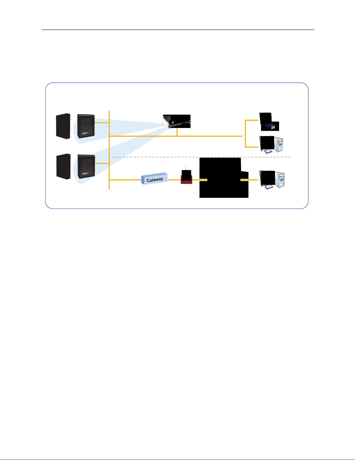
IPAC Server™ is an access control
appliance
and software interface that is compatible with
IPAC SYSTEM control panels, as well as other compatible control panels.
Figure 1.
IPAC Server™
Optional Remote Access
Local Administrator Access
Internet
Standard Web Browsers
LAN
IPDC
ST
A
T
U
S
ACTIVE
N
E
T
WO
R
K
IPAC
IPDC
ST
A
T
U
S
ACTIV
E
N
E
T
WO
RK
IPAC
Page 15

IPAC Server Administrator’s Manual Page 14 of 334
14
IPAC SYSTEM control panels in Client Mode
An IPAC SYSTEM panel is in Client Mode when it has been connected to an IPAC Server™
appliance and therefore becomes integrated into the IPAC Server™ system.
Figure 2.
IPAC SYSTEM Client Mode
WARNING: IPAC SYSTEM firmware changes
Once an IPAC SYSTEM panel has been
connected to an IPAC Server™ appliance,
its firmware has replaced and it can no
longer function as an independent panel.
NOTE:
The majority of this document assumes you have a single
System Account. For a description of how IPAC Server™
operates differently when Tenant Accounts are defined, see
the
Tenant Accounts
Section.
In situations where only one business occupies a building,
security is managed via a single System Account. If,
however, there are multiple businesses leasing portions of a
building, the System Account can be used to manage
building-wide security, while individual Tenant Accounts are
created for each business, enabling them to manage their
own internal security.
IPDC
STAT
US
ACT
IVE
NETWORK
IPAC
Page 16

IPAC Server Administrator’s Manual Page 15 of 334
15
Browser Requirements
You can use any standard Web browser to access the interface. Note that video playback
functionality may vary by DVR type. Please see specific DVR driver documentation for more
information.
The interface uses
cookies
to preserve session information. If your browser disallows
cookies, the interface will not function properly.
The interface uses JavaScript™ to validate form data, control navigation and display images.
If your browser has
scripting
disabled, the interface will not function properly.
Some functional elements appear in pop-up windows. If you have installed software that
blocks pop-up windows, the interface will not function properly.
Page 17

IPAC Server Administrator’s Manual Page 16 of 334
16
Main Features of the IPAC Server™
Application runs locally on the IPAC Server™ access control appliance
Up to 500,000 users
Up to 1,000 readers/doors
Customizable administrator roles
Supports the ability to add control panels and IPDCs
Supports Digital Video Playback with supported DVRs
Supports an integrated badging application
Supports interactive maps and floorplans
Supports varied threat levels for increased security
Supports global antipassback
Supports mustering
Supports reporting
Supports guard tours
Page 18

IPAC Server Administrator’s Manual Page 17 of 334
17
2. Network Environment
This section describes the basic operation of the IPAC Server™ series in an IP network
environment.
First, the network requirements are identified. Next, the steps for accessing IPAC Server™
are outlined.
Page 19

IPAC Server Administrator’s Manual Page 18 of 334
18
Networking Requirements
IPAC Server™ with multiple IPAC SYSTEM panels on a single LAN
The following network requirements are applicable to a system in which an IPAC Server™
appliance is managing one or more IPAC SYSTEM control panels on a single LAN (i.e., a
single IP subnet or address space), as shown in the figure below.
Figure 3.
IPAC Server™ on a single LAN
Requirements
Comment
Ethernet 10/100 Base T LAN
CAT5 Cabling with RJ45 Connectors
Ethernet Hub/Switch set to AutoNegotiate
Most hubs and switches default to
auto-negotiate, which is the preferred
setting.
IP Addressing – IPAC Server™
A static IP address is required for the
IPAC Server™ appliance. Consult your
local network administrator for a
suitable static IP address for the
appliance.
IP Addressing – IPAC SYSTEM
The IPAC SYSTEM panels being
controlled by the IPAC Server™
appliance may be configured with
either DHCP or a static IP address.
Please see the local network
administrator for a preferred
configuration for these settings.
Proxy (not required)
The existence of a proxy on the LAN
is not relevant to the IPAC Server™
because it is a Web server; however,
outside access to the appliance may
IPDC
STA
T
U
S
ACTIVE
NETWORK
IPAC
IPAC
Page 20

IPAC Server Administrator’s Manual Page 19 of 334
19
require the end user to be aware of
proxy settings for proper behavior of
his/her browser. Consult your local
network administrator for further
information about proxy settings.
IPAC Server™ with multiple IPAC SYSTEM panels on multiple LANs
The following network requirements are applicable to a system in which an IPAC Server™
appliance is managing one or more IPAC SYSTEM control panels on multiple LANs (i.e.,
typically multiple sites, each with their own connection to the Internet or a corporate WAN)
as shown in the figure below.
Figure 4.
IPAC Server™ with Multiple Panels on Multiple LANs
The following requirements for a multi-site IPAC Server™ network are in addition to the
requirements for a single LAN.
Requirements
Comment
Site-to-site (LAN-to-LAN) connectivity
The sites where the IPAC Server™
and IPAC SYSTEM equipment is
located must all be able to connect to
a common networking environment
such as the Internet or a corporate
WAN
IP routing
There must be an IP route
established between the sites where
the OnSite equipment is located.
IPAC
IPDC
STATU
S
A
CT
IVE
NETWO
R
K
IPAC
IPDC
STATU
S
A
CT
IVE
NETWO
R
K
Page 21

IPAC Server Administrator’s Manual Page 20 of 334
20
This must be performed by the
network administrator for those sites.
Typical approaches include VPNs,
public IP addresses, port forwarding,
etc. Contact the network
administrator to determine the proper
configuration.
Page 22

IPAC Server Administrator’s Manual Page 21 of 334
21
Adding an IPAC SYSTEM to the IPAC Server™
The IPAC Server™ appliance can support up to as many control panels as necessary for
their full reader capacity. The panels can be a mix of IPAC SYSTEM control panels with up
to fourteen expansion boards each and IPDCs.
In either case, the panels or IPDC must be individually configured with the IP address of the
IPAC Server™ appliance it will get data from.
In order to configure a panel or device, you will need the following:
• A network connection to the panel or device
• The IP address of the IPAC Server™ appliance
Refer to the documentation for the IPAC or IPDC for instructions on network access to those
devices.
The IP address of the IPAC Server™ appliance is available from the System Administrator.
To configure the panel or device to connect to an IPAC System or IPDC, do the following:
1. Open
HHHUhttp://
ip-address
/cgi-bin/server.cgiUHHH in a browser, where
ip-address
is the
address of the panel or device you are configuring.
2. In the Server IP Address box, enter the IP address of the IPAC Server™
appliance from where the panel or device will retrieve data.
Figure 5.
IPAC SYSTEM Client Mode
3. Click Save.
The panel or device will connect to the server and retrieve whatever firmware/settings are
necessary.
WARNING:
Do not interrupt the process once
started. If you make a mistake, let the
process finish before attempting to
correct. Interrupting the installation of
new firmware can damage the panel or
device functionality.
Please enter the IP address of the IPAC System that this panel should connect to.
The panel will contact the configured server and download firmware, then install that firmware.
Warning: All data is erased from the panel, and it becomes a client of the configured server.
IPAC Server Settings
Page 23

IPAC Server Administrator’s Manual Page 22 of 334
22
Adding an IPAC SYSTEM panel using manual handshake mode
Usually, Panel Discovery is the primary method by which the IPAC Server™ detects and
adds new panels. However, there are times when complex networking setups (firewalls,
WANs) do not allow for this. A secondary manual handshake process with instructions listed
below allows for a panel to be added to the IPAC Server™ in situations where Panel
Discovery is not used. A laptop will be required for this process.
1. Plug the laptop into the ADMIN port on the main board of the IPAC SYSTEM
panel.
2. Power the laptop on.
3. The panel must use firmware version 1.1.1 or later. To upgrade:
a) Open browser to “onsite.brivo.com”
b) Enter
admin into the username field and click Login.
c) Click the link that says “Click here if you have an ACS Onsite backup file you
wish to restore.”
d) Click the Upgrade Firmware option from the navigation menu on the left.
e) Click the Export Data button, and click “Cancel” on the “Save As” dialog box
that pops up.
f) Click the Browse button and select the brivo-onsite-1.1.1.bin file downloaded
from www.brivo.com
g) Click Upgrade. The upgrade process will take a few minutes.
4. Open your browser to http://onsite.brivo.com/cgi-bin/server.cgi
5. Enter the IP Address of the appliance into the field on the page.
6. Click Save.
7. The system will take a few minutes to handshake with the IPAC Server™
appliance.
The IPAC SYSTEM has now been configured to operate with the IPAC Server™ appliance.
Page 24

IPAC Server Administrator’s Manual Page 23 of 334
23
Accessing IPAC Server™
This section describes how to connect to the IPAC Server™ appliance.
In order to access IPAC Server™ you will need to:
Connect a laptop to the IPAC Server™ appliance
Set a static IP address
Alternately, you can use the IPAC Server™ Console Interface to configure a static IP
address. To do this you will need to:
Connect a monitor and keyboard to the IPAC Server™ appliance
Set a static IP address
Connecting to IPAC Server™ appliance from Laptop:
The IPAC Server™ will boot with a static IP address of: 169.254.242.207.
You will need to:
1. Connect your laptop to Ethernet Port 1 (clearly labeled) on the back of the
appliance.
Figure 6.
Back of IPAC Server™ appliance
2. Your laptop should default to an appropriate address on this same network (i.e.,
169.254.xxx.xxx); if it does not, please use the manual networking settings
tools on your laptop to configure it to an address on the 169.254.xxx.xxx
network).
3. Log on to your laptop and open a browser to http://169.254.xxx.xxx to access
IPAC Server™.
4. See the
Configuring the Network
section for information on how to assign a
static IP address for the LAN.
Page 25

IPAC Server Administrator’s Manual Page 24 of 334
24
Direct console:
The IPAC Server™ appliance supports a USB keyboard and monitor to present a basic
network configuration console-based interface. It is generally necessary to configure a static
IP address for the IPAC Server™ appliance. The Network Settings dialog prompts for static
address parameters.
NOTE
:
If DHCP is required, please use the initial static IP address for the
appliance to log into the main application and select DHCP
addressing.
1. Connect a VGA monitor and keyboard to appropriate ports on the IPAC Server™
appliance
2. Log in with username “admin” and no password (for first login) or use the
initially configured admin password.
3. To set a static IP address for the LAN, select Network Settings from the main
menu.
4. Enter the appropriate IP address information.
Figure 7.
IPAC Server™ direct console static IP setup
5. Press Enter to save settings.
Page 26

IPAC Server Administrator’s Manual Page 25 of 334
25
3. Home
The Home page is the initial page displayed after logging into the interface. The Home page
provides a list of Common Tasks and Reports available to the Administrator. The contents of
these lists can change dependent upon the permissions of the Administrator as defined by
their Administrator Role. For example, if an administrator could not add new cards, the Add
New Cards link would not appear in the Common Tasks list. For more information on the
setup and defining of Administrators and Administrator Roles, see the Accounts chapter.
Figure 8.
Home Page for IPAC Server™
Page 27

IPAC Server Administrator’s Manual Page 26 of 334
26
4. Status
The Status Page provides a two-fold administrative functionality for monitoring and
controlling the output behavior of programmable system devices, as well as the monitoring
of live device maps and floorplans.
On the Dashboard itself, the left side of the Dashboard page displays the Activity list. It is a
dynamic system Activity Log that automatically refreshes in three seconds or less with the
most recent events in reverse chronological order (i.e., most recent event at the top;
earliest event at the bottom) and associates these events with a time-stamp and the name
of the device involved. The right side of the Dashboard page displays the Device Status,
Hardware Status, and Schedule Status lists. The Device Status tab lists system devices in
alphabetical order, along with their lock/unlock status. The Hardware Status lists the
connection status of control panels associated with the account. The Schedule Status tab
lists schedules that are configured as group activated. For Administrators configured to use
it, the Device Status and Schedule Status lists also provides corresponding command button
mechanisms to control the output behaviors of specific devices or schedules.
On the Edit Device page, system devices
must
be configured for an output behavior of
Pulse, Latch or Unlatch
and
have the Control from browser option checked to be controllable
from the Device Status list on the Dashboard page. System devices configured for an output
behavior of Follow are
not
controllable from the Dashboard page.
There is a Status feature on the Dashboard that allows the user to see the physical position
of the door as open or closed, live video (if cameras and DVRs are configured), as well as
customized, color-coded messages for programmable devices. Programmable devices are
described in the section on Live Status in the chapter on
Devices
.
There is a Change Threat Level icon that enables certain Administrators to change the
current threat level. For more information, see the chapter on
Threat Levels
.
Users can control which device status is displayed on the Device Status section of the
Dashboard by creating Display Filters. For more information, see the section on
Using
Activity Filters.
Page 28

IPAC Server Administrator’s Manual Page 27 of 334
27
Browsing the Dashboard
The Dashboard page provides a dynamic system activity log that automatically refreshes
periodically with the most recent events (such as when a door is accessed or a device is
activated), along with the corresponding time-stamp and device name. Administrators with
appropriate permissions can view
all
system activity entries displayed on the Dashboard
page.
To view the Dashboard page:
From any other page in the system, click the Status link from the dropdown menu and
select Dashboard to access the Dashboard page.
Figure 9.
View Dashboard and Live Status
Details displayed include:
Activity
o Time. The time at which the event occurred.
o Event. The type of system activity event. There are three types of events that
may be listed.
i. Standard device-related events are shown in black. This includes such
occurrences as a door unlocking according to schedule or a timerdriven device turning itself on.
ii. For user access events, such as an authorized user entering a valid
PIN, the user’s name is listed in blue. Clicking on a user name takes
you to the corresponding User Detail page.
iii. Alarms and alert events, such as Door Forced Open or Failed Access
Attempt messages are displayed in red.
o Device. The device at which the event occurred. Clicking the device name
takes you to the corresponding Device Details page.
• Alarm Console
o Bulk Alarm Acknowledge Checkbox. Located to the far left of the screen next
to the Time header, this checkbox allows the administrator to select all
current alarm events.
Page 29

IPAC Server Administrator’s Manual Page 28 of 334
28
o Alarm Acknowledge Checkbox. Located to the left of each alarm event, this
checkbox allows the administrator to select an event(s).
o Time. The time when the event occurred.
o Event. The alarm or alert system activity event, such as Door Forced Open or
Failed Access Attempts.
o Details. The device where the alarm event occurred and if multiple alarms
have occurred in the same location, the number of events will follow the
location in parentheses.
o Acknowledge. Shows the number of selected alarm events and links to the
Alarm Details popup window. At least one alarm must be selected for the
Acknowledge link to work.
o Additional Information (+). This button calls up the Alarm Details popup
window for a specific alarm event, discussed further in the Alarm Text section
below.
• Swipe & Show
o User. The user name as well as the date and time of the swipe event.
o Device. A link to select which device to monitor in the upper right corner of
the Swipe & Show display area.
o Photo. A display of the photo on record pulled from the user profile. If no
photo is available, the Default User Icon is presented.
o Image Gallery. Shows the last eight valid credential reads displaying the user
name, time and date stamp, and photo on record from the user profile. If no
photo is available, the Default User Icon is presented.
NOTE:
With systems that have large amounts of data, the IPAC Server will
begin to immediately populate the device status, hardware status, and
schedule status pages but may take some time to completely finish
loading all devices, hardware, and schedules.
Device Status
o Name. The name of the logical device configured for use at your installation.
Clicking the device name takes you to the corresponding Device Details page.
In the case of Guard Tours, clicking on the arrow icon will expand or close the
details of the Guard Tour.
o Status. The current output behavior status of the logical device configured for
use at your installation. (The status of devices configured for an output
behavior of Follow will
not
be displayed.)
o If appropriate, buttons to control the state of the device will appear as well.
o If applicable, previously created Display Filters will be accessible via a
dropdown list.
• Hardware Status
o Name. The name of the control panel, or an indication that the panel has not
been configured.
Page 30

IPAC Server Administrator’s Manual Page 29 of 334
29
o Panel ID. The unique identifier that separates this panel from all others in the
system. Might be blank if a control panel has been configured, but has not
yet been given a physical Panel ID to be associated with.
o Status. The connection status of the panel and its IP address if connected.
o Note: Additional information may appear in the event that a panel requires
upgrade or other circumstances.
• Schedule Status
o Name. The name of the schedule. Clicking the schedule name takes you to
the corresponding Schedule Details page.
o Status. The current status of the schedule, showing either not activated or
activated until the date and time the schedule ends.
o Buttons to control the state of the schedule.
Administrators with appropriate permissions can:
Select a filter from the dropdown list in order to control which device status is displayed on
Device Status section of the Dashboard.
View the most recent activity events in the Activity list on the Dashboard page.
Click a user name in the Activity list on the Dashboard page to access the corresponding
User Details page.
Click a device name in the Device Status list on the Dashboard page to access the
associated Device Details page.
View and acknowledge alarm events on the Alarm Console page of the Dashboard.
View the Swipe & Show gallery and see the last valid access event (with photo, time, and
date) as well as click on a gallery photo image to call up that previous valid access event
(with photo, time, and date).
Page 31
IPAC Server Administrator’s Manual Page 30 of 334
30
Managing the Dashboard
Practically speaking, the Dashboard page is intended to give Administrators more immediate
control over their installation environment. The Pulse feature provides a standard remote
“buzz-through” access on doors for authorized users who may have forgotten their
credential, entered a PIN incorrectly several times, or attempted entry out-of-schedule. The
Latch/Unlatch toggle feature allows Administrators to intentionally latch or unlatch a
programmable device that is configured for that output behavior. The Lock Early/Unlock
Early/Follow Schedule feature allows Administrators to manually override a door locking
schedule to allow/disallow access under certain special circumstances.
Using the Dashboard’s Pulse Feature
The Dashboard’s Pulse feature provides a standard remote “buzz-through” access on doors
for authorized users.
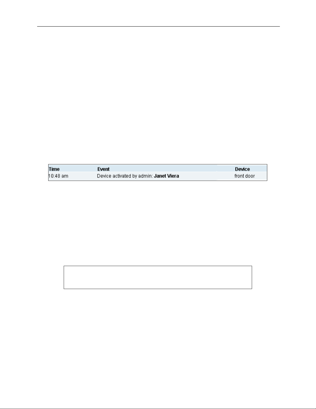
1. To pulse a device, click the Pulse button associated with it on the Dashboard's
Device Status list. The system displays the Device output pulsed dialog box.
2. Click OK to acknowledge the dialog. Within a few seconds, an event entry similar
to the example shown below displays at the top of the Dashboard's Activity list.
Figure 10.
Dashboard Activity List – Pulse Event Entry
Using the Dashboard’s Latch/Unlatch Feature
The Dashboard’s Latch/Unlatch toggle feature allows Administrators to intentionally latch or
unlatch a programmable device that is configured for that output behavior.
1. To latch a device, click the Latch button associated with it on the Dashboard's
Device Status list. The system displays the Device output latched dialog box.
2. Click OK to acknowledge the dialog. Within a few seconds, an event entry similar
to the example shown below is displayed at the top of the Dashboard's Activity
list.
Figure 11.
Dashboard Activity List – Latch Event Entry
3. To unlatch the device, click the Unlatch button associated with it on the
Dashboard's Device Status list. The system displays the Device output unlatched
dialog box.
4. Click OK to acknowledge the dialog. Within a few seconds an event entry similar
to the example shown below display at the top of the Dashboard's Activity list.
Page 32

IPAC Server Administrator’s Manual Page 31 of 334
31
Figure 12.
Dashboard Activity List – Unlatch Event Entry
Using the Dashboard’s Lock Early/Unlock Early/Follow Schedule Feature
The Dashboard’s Lock Early/Unlock Early/Follow Schedule feature allows administrators to
manually override a door timer schedule to allow/disallow access under certain special
circumstances. When desired, the Administrator can then return the door device to its
normal lock/unlock schedule.
NOTE:
Doors or devices that are overridden will only remain overridden until
the next scheduled event in the schedule, either to engage (lock) or to
disengage (unlock). The device or door still follows its schedule on the
next appropriate schedule block.
1. To lock a door
before
its normal scheduled time, click the Lock Early button
associated with it on the Dashboard's Device Status list. The system displays the
Door locked ahead of schedule dialog box.
2. Click OK to acknowledge the dialog. Within a few seconds an event entry similar
to the example shown below display at the top of the Dashboard's Activity list.
Figure 13.
Dashboard Activity List – Door Locked Event Entry
3. To unlock a door
before
its normal scheduled time, click the Unlock Early button
associated with it on the Dashboard's Device Status list. The system displays the
Door unlocked ahead of schedule dialog box.
4. Click OK to acknowledge the dialog. Within a few seconds an event entry similar
to the example shown below display at the top of the Dashboard's Activity list.
5. The “Activate Devices” field does not default to appear checked. You must check
this box to allow this Administrator to activate devices from the Dashboard.
Figure 14.
Dashboard Activity List – Door Unlocked Event Entry
6. To return a door to its normal lock/unlock schedule, click the Follow Schedule
button associated with it on the Dashboard's Device Status list. The system
displays the Door returned to following configured unlock schedule dialog box.
Page 33

IPAC Server Administrator’s Manual Page 32 of 334
32
7. Click OK to acknowledge the dialog. Within a few seconds, an event entry similar
to the example shown below display at the top of the Dashboard's Activity list.
Figure 15.
Dashboard Activity List: Door Returned to Unlock Schedule
To select a filter for devices displayed on the Dashboard
1. From the Status link at the top of any page, click on the Dashboard link.
2. Select a filter from the dropdown list next to Filter.
Figure 16.
Dashboard Display Filter
3. The corresponding device status for the selected filter will display. For more
information on how to create a filter, refer to the section on
Using Display
Filters.
Using the Dashboard’s Alarm Console Feature
The Dashboard’s Alarm Console feature allows administrators to view and acknowledge
alarm events either individually or in bulk. When desired, the administrator can enter
messages about alarm events on the alarm details page, acknowledging the alarm, updating
it for future review, or clearing them from the alarm console depending upon the type of
alarm event.
To enable the Alarm Console
1. From the Configuration dropdown menu, choose the Accounts tab and click on
the Accounts link. The list of Accounts will appear.
2. Select the account where you want to activate Alarm Console. The Edit Account
Details page appears.
3. Click Edit at the bottom of the Account Details page.
4. Check the Enable checkbox under Alarm Console Settings.
Page 34

IPAC Server Administrator’s Manual Page 33 of 334
33
5. If you only want alarms generated during a specific schedule to appear on the
alarm console and require acknowledgement, you may select a schedule from
the dropdown menu next to Alarm Active Schedule.
6. If you wish to assign a priority system to alarm events, you may input an Alarm
Priority Minimum and Alarm Priority Maximum as a numeric range.
7. You may ignore Threat Levels or select under what Threat level conditions the
device will report alarm events.
8. Click Save.
To enable Alarm for Control Panels
1. From the Configuration dropdown menu, choose the Accounts tab and click on
the Accounts link. The list of Accounts will appear.
2. Select the account where you want to activate Alarm Console. The Edit Account
Details page appears.
3. Click Edit at the bottom of the Account Details page.
4. If you want specific instruction text to appear when an alarm event for a control
panel occurs, select from the Instruction Text dropdown menu. See the Alarm
Text section of the manual on how to create instruction text.
5. You may assign an Alarm Priority to alarm events for control panels.
6. Click Save.
Figure 17.
Alarm Console Settings
Alarm Text
Alarm Text allows administrators with appropriate permissions to create instructions for
alarm events and precanned acknowledgements for use when reviewing and acknowledging
alarm events.
Page 35

IPAC Server Administrator’s Manual Page 34 of 334
34
To create new Alarm Text
1. From the Configuration dropdown menu, choose the Accounts tab and click on
the Alarm Text link. The Alarm Text list will appear.
2. Click on the Create New Alarm Text button.
3. Select the Type of alarm text you would like to generate from the dropdown
menu.
4. Type in a Summary to describe the alarm text.
5. Enter the Text of the alarm text into the provided field.
6. Click Save.
Figure 18.
Creating an Alarm Text Message
To acknowledge, update, or clear an Alarm Event(s)
1. From the Dashboard, click on the Alarm Console tab. The Alarm Console section
of the Dashboard displays all the listed alarm events.
2. Select a single alarm event by checking the checkbox on the left next to the
single alarm event, or you may select all events by checking the checkbox next
to Time at the top of the Alarm Console tab.
3. Click the + button or the Bulk link above it to take you to the Alarm Details
popup window.
4. If desired, select a precanned acknowledgement from the Canned Message
dropdown menu or simply enter information into the Message text field below.
5. To update an alarm event, click the Update Alarm button. This returns you to
the Alarm Console dashboard, and an Alarm Updated message appears in the
activity log along with any message entered into the Message text field.
6. To acknowledge an alarm event, click the Acknowledge Alarm button. You are
returned to the Alarm Console dashboard, and an Alarm Acknowledged message
appears in the activity log along with any message entered into the Message
text field.
7. To clear an alarm event, click the Clear Alarm button. You are returned to the
Alarm Console dashboard, and an Alarm Cleared message appears in red in the
activity log, along with any message entered into the Message field.
Page 36

IPAC Server Administrator’s Manual Page 35 of 334
35
NOTE: Clearing Alarms
Clearing an alarm removes an alarm event that is still not in its normal
state off of the alarm console. For example, normally a door ajar alarm
stays on the console until it is both acknowledged and the door is
closed again. If you want to remove the alarm event before actually
closing the door, you can acknowledge the alarm event, then bring up
the Alarm Details popup window again and press the Clear Alarm
button, which will forcibly remove the alarm event from the alarm
console.
Figure 19.
Alarm Update/Acknowledgement
Figure 20.
Alarm Clear
Enabling Alarm Events for Doors, Valid Credential Devices, and Elevators
An administrator with appropriate permissions can enable alarm events for doors, valid
credential devices, and elevators by defining the privileges on the Edit Device page. This
allows failed access events to appear as alarms, as well as allowing the combination of
multiple alarm events of the same type into a single reported alarm event.
Page 37

IPAC Server Administrator’s Manual Page 36 of 334
36
To enable alarm events for doors, valid credential devices, and elevators
1. From the Configuration dropdown menu, choose the Devices tab and then click
on Devices. If you are enabling an existing device to use Alarm Console, simply
click on the device you wish to enable and click Edit at the bottom of the Device
Details page, then skip to step 5.
2. Click on the Create New Device button.
3. Select the Type of device from the dropdown menu, choosing Door, Valid
Credential Device, or Elevator.
4. Select a Subtype if you wish to make this a device profile.
5. In the Alarm Console Settings section of the page, check the Include failed
access as alarm checkbox if you wish to include failed access events as alarm
events.
6. Check the Combine Alarms checkbox if you wish to combine multiple alarm
events of the same type into a single reported alarm event.
7. Enter Instruction text if desired.
8. Enter an Alarm Priority if desired.
9. Select an Alarm Active Schedule from the dropdown menu if desired. If a
schedule is selected here, the alarm events will appear during the selected
schedule as well as during any selected schedule under the Alarm Console
Settings for the entire account.
10. You may ignore Threat Levels or select under what Threat level conditions the
device will report alarm events.
11. Click Save.
Figure 21.
Alarm Console Settings for Doors, Valid Credential Devices, and Elevators
Enabling Alarm Events for Event Triggers, Input Switches, and Schedule Controlled Devices
An administrator with appropriate permissions can enable alarm events for event triggers,
input switches, schedule controlled devices, and muster points by defining the privileges on
the Edit Device page. This allows standard events to appear as alarms, as well as allowing
the combination of multiple alarm events of the same type into a single reported alarm
event.
Page 38

IPAC Server Administrator’s Manual Page 37 of 334
37
To enable alarm events for event triggers, input switches, and schedule controlled devices
1. From the Configuration dropdown menu, choose the Devices tab then click on
the Devices link. If you are enabling an existing device to use Alarm Console,
simply click on the device you wish to enable and click Edit at the bottom of the
Device Details page, then skip to step 5.
2. Click on the Create New Device button.
3. Select the Type of device from the dropdown menu, choosing event trigger,
input switch, schedule controlled device, or muster point.
4. Select a Subtype if you want to make this a device profile.
5. In the Alarm Console Settings section of the page, check the Standard events as
alarm checkbox if you wish to include standard events as alarm events.
6. Check the Combine Alarms checkbox if you wish to combine multiple alarm
events of the same type into a single reported alarm event.
7. Enter Instruction text if desired.
8. Enter an Alarm Priority if desired.
9. Select an Alarm Active Schedule from the dropdown menu if desired. If a
schedule is selected here, the alarm events will appear during the selected
schedule as well as during any selected schedule under the Alarm Console
Settings for the entire account.
10. You may ignore Threat Levels or select under what Threat level conditions the
device will report alarm events.
11. Click Save.
Figure 22.
Settings for Event Triggers, Input Switches, Etc.
Using the Dashboard’s Swipe & Show feature
The Dashboard’s Swipe & Show feature allows administrators to view valid credential events
at a selected device, seeing the current and the seven previous events. When desired, the
administrator can select any of the photos in the gallery and call up the photo, time, and
date of that particular valid credential event.
Page 39

IPAC Server Administrator’s Manual Page 38 of 334
38
To use Swipe & Show
1. From the Status dropdown menu, select Dashboard.
2. Click on the Swipe & Show tab of the Dashboard.
3. Click on the Select Device link in the upper right hand corner of the Swipe &
Show section. The Select Device popup window appears.
4. Choose a device from the available list by clicking on it. You are returned to the
Swipe & Show page.
5. The last valid credential device read displays the user name, as well as the time
and date stamp of the read, along with the photo image attached to the user
profile.
6. The last eight valid credential device reads along with their respective photo
images display along the bottom of the page. Selecting any of the images from
the gallery at the bottom recalls the user photo and the time and date of last
access.
7. As new valid credential reads occur, the oldest image is removed and the newest
image is placed at the beginning of the line.
Figure 23.
Swipe & Show display
Page 40

IPAC Server Administrator’s Manual Page 39 of 334
39
Using Display Filters
IPAC Server™ allows users to control the devices for which status displayed on the Device
Status section of Dashboard by creating Display Filters.
To view filters
1. Scroll over the Configuration link. The sub-navigation menu displays.
2. From the Dashboard link, click Display Filters. The Display Filters page displays.
Figure 24.
Filters
3. To view the details for a particular filter, click on the filter’s name. The Filter
Details page displays.
Figure 25.
Filter Details
To create a filter
1. Scroll over the Configuration link. The sub-navigation menu displays.
2. From the Dashboard link, click Display Filters. The Display Filters page displays.
3. Click “Create New Filter” at the top of the page. The “Edit Filter” page will
display.
Page 41

IPAC Server Administrator’s Manual Page 40 of 334
40
Figure 26.
Create New Filter
4. In the field next to “Name,” enter a name for the filter.
5. Click to select which device(s) will appear in the filter. A popup list will
appear. Select each new device to add to the filter which will then appear in the
Selected Devices box.
6. Click Save. You are returned to the Filter Details page.
To edit a filter
1. Scroll over the Configuration link. The sub-navigation menu displays.
2. From the Dashboard link, click Display Filters. The Display Filters page displays.
3. Click the filter you wish to edit. The Filter Details page displays.
4. Click “Edit Filter” at the bottom of the page. The “Edit Filter” page will display.
5. When you have finished making changes to the filter, click Save. You are
returned to the Filter Details page.
To delete a filter
1. Scroll over the Configuration link. The sub-navigation menu displays.
2. From the Dashboard link, click Display Filters. The Display Filters page displays.
3. Click the filter you wish to delete. The Filter Details page displays.
4. Click “Delete” at the bottom of the page. Click OK in the confirmation prompt.
You are returned to the Filters page.
Page 42

IPAC Server Administrator’s Manual Page 41 of 334
41
Live Map/Floorplan
Once a map/floorplan has been created, icons added, and regions established, then an
administrator with appropriate permissions can utilize the Live Map feature under the
Dashboard link.
To use the Live Map feature:
1. Scroll over the Status link. The sub-navigation menu displays.
2. From the sub-navigation menu, click the Maps/Floorplans link. A popup window
with a list of map names appears. Select the map you wish to use.
3. The Live Map page will appear with the icons and regions in their current states
(either normal or alarm).
NOTE:
An icon representing a programmable device or door will appear as its
normal color (default is green) if in a normal state (such as unlocked or
locked). The icon will switch to its alarm color (default red) if in an
alarm state such as door ajar or wire cut.
4. To interact with a device, scroll over the icon representing that device. The
name and current status of the device will appear in a popup window.
5. If the device can be controlled via the browser, if you click on the icon, a button
will appear (for example, Pulse for a door).
6. Zoom – to zoom in, out, or reset the default size of the live map, there are three
buttons in the upper right hand corner of the screen (+), (-), and (fit).
7. Choose Map – to choose a new map for live view, click on the Choose Map
button and a popup window with available maps will appear. Select the map
you wish to view live and you are returned to the Live Map page.
Figure 27.
View Live Map
Page 43

IPAC Server Administrator’s Manual Page 42 of 334
42
5. Accounts
Page 44

IPAC Server Administrator’s Manual Page 43 of 334
43
What is an Account?
An
account
is essentially a “span of control.” With the IPAC Server™ family of applications,
there is usually only one account: the System Account. This is the account that manages
the overall facility at which the system is installed. The control of all doors, exterior and
interior, as well as all devices, is managed by this one account.
If sections of the facility are leased out, then there may also be one or more Tenant
Accounts in addition to the System Account. In cases such as this, the System Account is
used to manage the overall facility, such as access to lobby doors or a cafeteria. Tenant
Accounts, on the other hand, are used to manage the access of user groups associated with
the tenant organization.
NOTE:
Administration permissions to sub-accounts are controlled by the rolebased administration settings. Roles can be granted permissions to
sub-accounts, so system account administrators can be given as
restricted as needed set of capabilities in sub-accounts.
Page 45

IPAC Server Administrator’s Manual Page 44 of 334
44
Defining the Initial System Account Administrator
An Administrator with full permissions must be defined for the System Account before any
other data is entered. When you first log in to the System Account, you are automatically
taken to the Welcome page and prompted to create a System Account Administrator.
To log in for the first time:
1. In your web browser, enter the address for the IPAC Server™.
2. The Log In page displays.
Figure 28.
Log In
3. In the Username field, enter admin.
4. Leave the Password field blank.
5. Click Login. The Welcome page displays.
Page 46

IPAC Server Administrator’s Manual Page 45 of 334
45
Figure 29.
System Account Administrator Creation Page
To define the initial System Account Administrator
1. In the First Name, Middle Name and Last Name fields enter the first, middle, and
last names of the Administrator for the System Account. The first name and last
name are required fields.
2. If you want a photograph linked to this administrator, you may click on either
the Take Photo button to use a webcam or the Upload Image to upload an
already existing image.
3. The Username defaults to
admin. For security reasons, you may want to
change the Username of the System Account Administrator, but you are not
required to do so.
4. Select a Preferred Language from the dropdown list.
5. Select a Preferred Date Format from the dropdown list.
6. In the Password field, enter a password for the Administrator. Re-enter the
exact same password in the Confirm Password field. Both of these fields are
required.
7. Select an Email for the System Account Administrator.
Page 47

IPAC Server Administrator’s Manual Page 46 of 334
46
NOTE:
The password that is set on this first page is used to control access to
the console configuration for IPAC Server™. After setting up your
initial Administrator, you will need to use that password with the
username ‘admin’ to log into the console. The password may then be
changed from the console if necessary.
Do not lose this password, or you will not be able to log into the
console interface in the future without it.
NOTE:
The Username and Password fields are required for all Administrators.
The username and password combination determine the
Administrator’s access to the IPAC Server™ application, and must be
entered the next time the Administrator logs in.
8. Click Save and continue to Account Setup. The Edit Account Details page
displays.
To set up the System Account:
Figure 30.
Set up System Account
1. After defining a System Account Administrator, you are prompted to name the
System Account and identify a main contact for it. Other than Name, all of the
fields on this page are optional.
Page 48

IPAC Server Administrator’s Manual Page 47 of 334
47
2. Enter the Name for the System Account. If the facility is occupied by a single
business, you probably want to use the name of that business. If the facility has
more than one tenant, you may want to use the building name, the building
address, or the landlord’s name.
3. Enter the Main Contact for the System Account. This is the person primarily
responsible for the operation of IPAC Server™ at this facility. For Tenant
Accounts, the main contact is the person who deals with the System Account
management company.
4. Enter the complete Address for the main contact. The format of this address will
vary depending on the location of the facility. For example, in the United States
the address should include a street number and name on line, possibly a suite or
office number on the second line, and the city, state and zip code on the last
line.
5. Enter the complete Phone number for the main contact. The format of the phone
number will vary depending on the location of the facility. For example, in the
United States the phone number should include a 3-digit area code, a 7-digit
number, and possibly an extension.
6. Enter an Email address for the main contact.
7. Enable Threat Level functionality. Check the “Enable Threat Levels” to be able to
use Threat Level functionality.
8. Click Save and Finish Setup. The System Activity page displays. You are now
ready to begin configuring the system. See the section on
System Management
.
Page 49

IPAC Server Administrator’s Manual Page 48 of 334
48
Viewing Account Details
Administrators with appropriate permissions can view basic account information on the
Account Details page. This overview displays contact information for the account as well as
a list of Administrators and devices defined for the account.
To view details for a specific account:
1. Scroll over the Configuration link at the top of any page. The sub-navigation
menu displays.
2. From the Account link, click Account Details. The Account Details page displays.
Figure 31.
View Account Details
Details displayed include:
Main Contact. The name of the person primarily responsible for the operation of the system
at this facility
Address. The complete mailing address for the main contact for the account.
Phone. The phone number(s) for the main contact.
Email. The email address for the main contact.
Enable Threat Levels. Whether or not the account has Threat Level functionality enabled.
Alarm Console Settings. Whether or not this account has Alarm Console functionality
enabled, and if enabled, when alarms are active, any alarm priorities that have been set,
and if alarms are linked to specific threat levels.
Alarm for Control Panels. Whether or not there are any alarm texts for control panel alarm
Page 50
IPAC Server Administrator’s Manual Page 49 of 334
49
events and what the alarm priority is for those events.
Password Complexity Rules. Whether or not the password rules for the account will follow:
o A minimum password length (the default is 8 characters).
o Requiring at least one non-alphanumeric character.
o Requiring at least one upper-case and one lower-case letter.
o Requiring at least one numeric character.
Statistics. Shows the number of Users, Groups, Schedules, Account Administrators, and
Devices for the selected account.
NOTE:
Administrator status is assigned to a user on the Administrators page.
See Creating an Administrator for more information.
NOTE:
Doors and devices are defined in the Devices section. See the section
on
Managing Devices
for more information.
Administrators with appropriate permissions can:
Click Back to List to return to the Accounts list.
Click Create New Account to access a blank Edit Account Details page in order to create a
new Tenant Account.
Click Edit to access the Edit Account Details page associated with this account.
Page 51

IPAC Server Administrator’s Manual Page 50 of 334
50
Creating Tenant Accounts
By default, the account you create when you first log in is automatically defined as the
System Account. All subsequent accounts are automatically defined as Tenant Accounts.
Only Administrators with appropriate permissions can create new Tenant Accounts.
To create a Tenant Account:
1. Scroll over the Configuration link at the top of any page. The sub-navigation
menu displays.
2. From the Account link, click Account Details. The Account Details page displays.
3. Click Create New Account. The Edit Account Details page displays with blank
fields.
Figure 32.
Create Tenant Account
4. In the Name field enter a descriptive name for the account, such as the name of
the business. This is the only required field on this page
5. In the Main Contact field enter the name of the person primarily responsible for
managing the interface for this account.
Page 52

IPAC Server Administrator’s Manual Page 51 of 334
51
6. In the Address field enter the complete address for the person identified as the
main contact. The format of this address will vary depending on the country in
which the account is located. For example, in the United States the address
should include the street number and name, office number, city, state, and zip
code.
7. In the Phone field enter the complete phone number for the person identified as
the main contact. As with the address, the format of the phone number will
depend on the country. In the United States, this field would contain a threedigit area code, a seven-digit number, and possibly an extension.
8. In the Email field enter the email address for the main contact.
9. Enable Threat Level functionality for the account. Check the “Enable Threat
Levels” to be able to use threat levels on the tenant account.
10. Enable Alarm Console Settings functionality for the account. Check the “Enable”
checkbox to set scheduling, priority, and threat level functionality.
11. In the Password Complexity Rules section, enter the required minimum
password length, and whether or not the password will require nonalphanumeric, upper-case and lower-case, and/or numeric characters.
12. Click Save. At the top of the page, the active account displays. To change the
active account, click on the Active Account link and select the new Active
Account from the list.
Figure 33.
View Active Account
NOTE:
You now have a multi-account setup. See Tenant Accounts for
guidelines on managing these accounts.
Page 53

IPAC Server Administrator’s Manual Page 52 of 334
52
13. If you choose not to assign an Administrator to the new account, you can:
o Click Create New Account to create another Tenant Account without first
assigning an Administrator to this one. You can always assign an Administrator at
a later time.
o Click Back to List to return to the Accounts list without first assigning an
Administrator to this account. You can always assign an Administrator at a later
time.
o Click Edit to access the Edit Account Details page to make changes to this
account before first assigning an Administrator.
o Click Delete to remove the account from the system.
NOTE:
If there are no Administrators with permissions to a Tenant Account,
the tenant will not be able to log in to the account, and the account will
remain under the complete control of the System Account until an
Administrator is assigned.
Page 54

IPAC Server Administrator’s Manual Page 53 of 334
53
Managing Account Contact Information
Once an account is created, all contact information can be edited by any Account
Administrator with appropriate permissions.
To edit account contact information:
1. Scroll over the Configuration link at the top of any page. The sub-navigation
menu displays.
2. From the Account link, click Account Details. The Account Details page displays.
3. Click Edit. The Edit Account Details page displays.
Figure 34.
Edit Account Details
4. You can change the account Name, but you cannot delete it. This is the only
required field on this page.
5. Update the remaining fields according to the procedures for creating tenant
accounts.
6. Enable Threat Levels functionality for the account. If you choose to allow the
account to be able to use Threat Levels, click the “Enable Threat Levels” box.
7. Enable Alarm Console Settings for the account. If you choose to allow the
account to use Alarm Console Settings, click the “Enable” box.
8. Edit Password Complexity Rules for the account as needed.
9. Click Save. You are returned to the Account Details page with the updated
information displayed.
Page 55

IPAC Server Administrator’s Manual Page 54 of 334
54
6. Administrators and Administrator
Roles
Administrators are people with access to IPAC Server™, the web-based interface. These
permissions are defined by the administrator roles feature, which details very specifically
what sections of the interface an administrator has access to as well as what processes an
administrator is allowed to use.
The creation of the first administrator, or System Administrator, is detailed in the previous
chapter.
Page 56

IPAC Server Administrator’s Manual Page 55 of 334
55
To view current administrators:
1. Scroll over the Configuration link. The sub-navigation menu displays.
2. From the Account link, select Administrators. The Administrators List page
displays.
Figure 35.
View Current Administrators
To create a new administrator:
1. Scroll over the Configuration link. The sub-navigation menu displays.
2. From the Account link, select Administrators. The Administrators List page
displays.
3. Click on the Create New Administrator button.
Figure 36.
Create New Administrator
4. Click on the User link. The Select User popup window will appear. Select the
user to link to this administrator or click the None (Leave selection blank)
button. If you click the None (Leave selection blank) button, you are not able to
save the administrator.
Page 57

IPAC Server Administrator’s Manual Page 56 of 334
56
5. Select a Username for this administrator.
6. Select a Preferred Language from the dropdown list.
7. Select a Preferred Date Format from the dropdown list.
8. Select a Password for the new administrator and enter it again in the Confirm
Password field. The required Password Complexity Rules are listed above the
Password field.
9. Select one or more Available Roles and click on the left arrow to move the
administrator roles from the right box to the left.
10. Click Save. You are returned to the Administrator Details page.
Figure 37.
View Administrator Details
To edit an administrator:
1. Scroll over the Configuration link. The sub-navigation menu displays.
2. From the Account link, select Administrators. The Administrators List page
displays.
3. Click on the administrator you wish to edit. The Administrator Details page
displays.
4. Click Edit. The Edit Administrator page displays.
5. Update the necessary fields and click Save. You are returned to the
Administrator Details page.
To delete an administrator:
1. Scroll over the Configuration link. The sub-navigation menu displays.
2. From the Account link, select Administrators. The Administrators List page
displays.
3. Click on the administrator you wish to delete. The Administrator Details page
displays.
4. Click Delete and click OK in the confirmation popup window. You are returned to
the Administrators List page.
Page 58

IPAC Server Administrator’s Manual Page 57 of 334
57
WARNING: Deleting Administrators
Deleting an administrator cannot be undone. Do not delete an
administrator without being fully aware of the consequences.
WARNING: No Administrators Left!
“Warning: There are no administrators on this account with full access.
Please create an administrator login with full access to this account
before performing any other user operations.”
If you get this message while deleting a user or administrator, you
have attempted to disable the last administrator with full access to this
system. Please make sure another administrator has full access before
disabling this one.
Page 59

IPAC Server Administrator’s Manual Page 58 of 334
58
Administrator Roles
Administrator roles are an assigned set of permissions that allow an administrator access to
the various sections of the IPAC Server™. For example, the IPAC Server™ provides a few
preloaded administrator roles, one of which is called Receptionist. An administrator who
has been given the role of receptionist has the capability to view and modify device status
and to view activity. If additional permissions are desired, a new administrator role can be
created or an existing administrator role can be edited to add new permissions.
Administrators can be assigned a number of different roles, all granting different
permissions. If any action is granted by a role, an administrator with that role is allowed
that action regardless of other roles the administrator may have.
Each account in the system has a reserved role, called System Administrator or Account
Administrator (for the system and sub-accounts respectively). These roles cannot be
modified or deleted, and have certain permissions that cannot be granted to other roles.
For example, the ability to create and edit new administrator roles is restricted to the
reserved role only. As a special case, the System Administrator role must always be
assigned to at least one administrator. This protects against accidental complete system
lock-out.
To view administrator roles:
1. Scroll over the Configuration link. The sub-navigation menu displays.
2. From the Account link, select Administrator Roles. The Administrator Roles List
page displays.
Figure 38.
View Administrator Roles
Page 60

IPAC Server Administrator’s Manual Page 59 of 334
59
Definitions of Permissions
Below is a list of definitions for each of the various permissions allowed when setting up or
editing an administrator role.
Administrator Controls
View – allows an administrator to view content for a particular permission.
Modify – allows an administrator the ability to modify data in relation to a particular
permission.
Create – allows an administrator the ability to create new data in relation to a particular
permission.
Delete – allows an administrator to delete data in relation to a particular permission.
Allow – allows an administrator the right to perform an action in regards to a particular
permission.
Targets – refers to the entities within an account that this permission will be affecting.
Permissions:
Make System Backup – allows an administrator with this permission to perform a system
backup of the IPAC Server™.
System Settings – allows an administrator to view and/or modify the system settings of the
IPAC Server™, including things like system date/time, upgrading the firmware, and license
keys.
Network Settings – allows an administrator to view and/or modify the network settings of
the IPAC Server™, including things like network configuration or panel discovery.
Database – allows an administrator to view and/or modify the database of the IPAC
Server™. This includes such activities as bulk user imports, and backing up and restoring
the full application database.
Accounts - allows an administrator to view and/or modify information related to one or more
accounts of the IPAC Server™.
Administrators – allows an administrator to view, modify, create, and/or delete
administrators on the IPAC Server™.
Administrator Roles – allows an administrator to view administrator roles.
Users – allows an administrator to view, modify, create, and or delete users in the IPAC
Server™ database.
Manage User Group Memberships – allows an administrator to view and/or modify the group
members of users in the IPAC Server™ database for one or more accounts.
Custom Field Definitions – allows an administrator to view, modify, create, and/or delete
custom fields of the IPAC Server™ for one or more accounts.
Custom Field Data – allows an administrator to view and/or modify the data in custom fields
in the IPAC Server™ database for one or more accounts.
Cards – allows an administrator to view, create, and/or delete cards in the IPAC Server™.
Page 61

IPAC Server Administrator’s Manual Page 60 of 334
60
Card Formats – allows an administrator to view, modify, create, and/or delete card formats
in the IPAC Server™.
Badge Templates – allows an administrator to view, modify, create, and/or delete badge
templates in the IPAC Server™.
Print Badge – allows an administrator to print badges in from a given set of badge
templates on the IPAC Server™.
Control Panels – allows an administrator to view, modify, create, and/or delete control
panels associated with the IPAC Server™.
Devices – allows an administrator to view, modify, create, and/or delete devices in the IPAC
Server™.
Device Status – allows an administrator to view and/or modify the status of devices
associated with the IPAC Server™ for a given set of devices.
DVR Drivers – allows an administrator to view, create, and/or delete DVR drivers for the
IPAC Server™.
Filters – allows an administrator to view, modify, create, and/or delete filters in the IPAC
Server™.
Groups – allows an administrator to view, modify, create, and/or delete groups in the IPAC
Server™.
Holidays – allows an administrator to view, modify, create, and/or delete groups in the IPAC
Server™.
Maps – allows an administrator to view, modify, create, and/or delete maps in the IPAC
Server™.
Email Notifications – allows an administrator to view, modify, create, and/or delete email
notifications in the IPAC Server™.
Schedules – allows an administrator to view, modify, create, and/or delete schedules in the
IPAC Server™.
Threat Levels – allows an administrator to view, modify, create, and/or delete threat levels
in the IPAC Server™.
Antipassback Zones – allows an administrator to view, modify, create, and/or delete
antipassback zones in the IPAC Server™.
Activity – allows an administrator to view activity in the IPAC Server™.
Administrative Journal – allows an administrator to view the Administrative Journal in the
IPAC Server™.
Change Threat Level – allows an administrator to change the threat level in the IPAC
Server™ for one or more accounts.
Schedules Status – allows an administrator to view and/or modify the status of schedules in
the IPAC Server™ for one or more accounts.
Reset Antipassback Zones – allows an administrator to reset antipassback zones in the IPAC
Server™ for one or more accounts.
View Live Video – allows an administrator to view live video in the IPAC Server™ for one or
more accounts.
Page 62

IPAC Server Administrator’s Manual Page 61 of 334
61
View Archive Video – allows an administrator to view archive video in the IPAC Server™ for
one or more accounts.
Alarm Console Settings – allows an administrator to view, modify, create, and delete the
alarm console settings in the IPAC Server™ for one or more accounts.
Alarm Console – allows an administrator to acknowledge the alarm console for one or more
accounts.
Alarm Bulk Acknowledge – allows an administrator the right to bulk acknowledge alarm
events on the alarm console.
Reports – allows an administrator the right to view, modify, create, and delete reports.
Scheduled Reports – allows an administrator the right to view, modify, create, and delete
scheduled reports.
To create an administrator role:
1. Scroll over the Configuration link at the top of any page. The sub-navigation
menu displays.
2. From the Account link, click Administrator Roles from the dropdown list. The
Administrator Roles list displays.
3. Click Create New Administrator Role. The Edit Administrator Role page displays.
Page 63

IPAC Server Administrator’s Manual Page 62 of 334
62
Figure 39.
Create New Administrator Role
4. Enter a Role Name for the new Administrator Role.
5. Select which Accounts in which you wish this Administrator Role to be used. If
you wish it to be used in all accounts, simply check the All Accounts checkbox.
6. If you wish this administrator role to be limited by a specific schedule, click on
the Limiting Schedule link and select the appropriate schedule from the popup
window.
7. You may have the administrator role ignore the Threat Level, or select under
what threat level condition the administrator role will function.
8. Select which Permissions this administrator role will have. See Definitions of
Permissions above for details on each permission.
9. When finished, click Save. You are returned to the Administrator Role List page.
Page 64

IPAC Server Administrator’s Manual Page 63 of 334
63
To edit an administrator role:
1. Scroll over the Configuration link at the top of any page. The sub-navigation
menu displays.
2. From the Account link, click Administrator Roles from the dropdown list. The
Administrator Roles list displays.
3. Click on the administrator role you wish to edit. The Administrator Role Details
page displays.
4. Click Edit. The Edit Administrator Role page displays.
5. When you have finished making changes to the administrator role, click Save.
You are returned to the Administrator Role Details page.
To delete an administrator role:
1. Scroll over the Configuration link at the top of any page. The sub-navigation
menu displays.
2. From the Account link, click Administrator Roles from the dropdown list. The
Administrator Roles list displays.
3. Click on the administrator role you wish to delete. The Administrator Role
Details page displays.
4. Click Delete. A popup box appears warning you this action is permanent. Click
OK. You are returned to the Administrator Roles list page.
NOTE:
Any administrators using a deleted role will simply lose any permissions
that role allowed them to use, unless duplicated by another role that
they also have assigned. If the deleted administrator role was the only
role assigned to them, their admin login will still work, but they will
have no ability to use the system other than to change their password.
To copy an administrator role:
For ease of use, administrator roles can be duplicated using a copy feature. This allows, for
example, a certain set of permissions to be used multiple times for different accounts
without having to recreate the role manually every single time.
1. Scroll over the Configuration link at the top of any page. The sub-navigation
menu displays.
2. From the Account link, click Administrator Roles from the dropdown list. The
Administrator Roles list displays.
3. Click on the administrator role you wish to copy. The Administrator Role Details
page displays.
4. Click Copy This Role. The Edit Administrator Role page displays with all of the
details of the copied role.
5. Enter a new Role Name for the new role.
6. Make any addition changes as needed. When finished, click Save. You are
returned to the Administrator Role Details page.
Page 65

IPAC Server Administrator’s Manual Page 64 of 334
64
7. Schedules and Holidays
Page 66

IPAC Server Administrator’s Manual Page 65 of 334
65
What are Schedules?
A
schedule
is an editable, reusable time template that can be used to control such things as
when a door is accessible or when a device is activated. A user’s access privileges are the
result of a three-way relationship that is created between: (1) a group of users, (2) a
secured device, and (3) a schedule.
A group of users is permitted access to a device, such as a door, according to a predefined
schedule. This access is granted on the Edit Group page. (Refer to the section on
Creating a
Group
.) This page lets you define access to single door or device differently for individual
groups of users. For example, the group “Staff” may have access to the “Front Door”
according to the schedule “Work Day,” which allows them to access the door, using a valid
credential, between the hours of 7:00AM and 6:00PM. At the same door, the group
“Cleaning Crew” may have access according to the “Night Shift” schedule, permitting them
access only during the hours of 8:00PM and midnight.
Schedules also allow one-time active or inactive blocks to be defined. For example, if a
training session will be taking place at 7:00 PM to 10:00 PM on the 1
st
of the month, the
“Work Day” schedule can add a one-time change to the schedule allowing the “Staff” group
to have access to the facility until 10:00 PM on that day. Additionally, monthly recurring
schedule blocks can be defined as well, for example, if the training session were to become
a monthly occurrence.
A door can also be assigned an Unlock Schedule, which specifies a period of time during
which no credential is required to access the door; all users have free access during the
Door Unlock Schedule period. Likewise, a device may be assigned an Active Schedule, a
period during which the device is in operation. Before any of these devices are created, you
must first define the schedule according to which they will operate. (For more information
on devices, see the section on
Managing Devices
.)
Page 67

IPAC Server Administrator’s Manual Page 66 of 334
66
What are Holidays?
An observed holiday is a specific time period during which schedules refer to their Holiday
override columns instead of to the day of week. If a schedule’s Holiday column is blank, the
schedule will not be active during that time period.
Page 68

IPAC Server Administrator’s Manual Page 67 of 334
67
Browsing the Schedules List
The Schedules list displays a list of all schedules currently defined for the account.
Administrators with appropriate permissions can view the schedules associated with their
own accounts.
To view the list of schedules:
1. Scroll over the Configuration link at the top of any page. The sub-navigation
menu displays.
2. From the Scheduling link, click Schedules. The Schedules list page displays.
Figure 40.
View Schedules List
Details displayed include:
This page lists all the schedules currently defined for the account. Two schedules are
defined automatically when the System Account is first created: “Always” and “Monday –
Friday 9-5”.
Administrators with appropriate permissions can:
Click a schedule to access the corresponding Schedule Details page.
Click Create New Schedule to access a blank Edit Schedule page in order to define a new
schedule.
Page 69

IPAC Server Administrator’s Manual Page 68 of 334
68
Viewing Schedule Details
Administrators with appropriate permissions can view basic schedule information on the
Schedule Details page. This overview indicates the times during which the selected schedule
is active.
To view details for a specific schedule:
1. Scroll over the Configuration link at the top of any page. The sub-navigation
menu displays.
2. From the Scheduling link, click Schedules. The Schedules list page displays.
3. Click the schedule you want to view. The corresponding Schedule Details page
displays.
Figure 41.
View Schedule Details
Details displayed include:
For each day of the week, Sunday through Saturday, this page indicates the “on” periods for
the selected schedule. In other words, when this schedule is assigned to a door, these are
the periods during which the door is automatically unlocked. When it is assigned to a group,
these are the periods during which users may access the device(s) for which they have
privileges. Schedules may be affected by Threat Levels and the Threat Level indicator shows
if a schedule is affected or if the schedule ignores Threat Levels (as above).
Administrators with appropriate permissions can:
Click the name of the Activating Group to access the associated Group Details page.
Click Back to List to return to the Schedules list.
Click Create New Schedule to access a blank Edit Schedule page in order to create a new
schedule.
Click Edit to access the Edit Schedule page associated with this schedule.
Click Delete to remove the schedule from the system.
Page 70

IPAC Server Administrator’s Manual Page 69 of 334
69
Creating a Schedule
Administrators with appropriate permissions can create new schedules.
NOTE:
Please refer to the section on Creating a Group Enabled Schedule
before assigning an activating group to any schedule or
unchecking the Auto-Deactivate checkbox.
To create a schedule:
1. Scroll over the Scheduling link at the top of any page. The sub-navigation menu
displays.
2. From the sub-navigation menu, click Schedules. The Schedules list page
displays.
3. Click Create New Schedule. The Edit Schedule page displays with blank fields.
Figure 42.
Create New Schedule
4. Enter a brief, descriptive Name for the schedule, such as “Night Shift” or
“Cleaning Crew.”
Page 71

IPAC Server Administrator’s Manual Page 70 of 334
70
5. If this is a Group Enabled Schedule, select the Enabling Group from the dropdown list and enter an associated Grace Period. Please refer to the section on
Creating a Group Enabled Schedule
before assigning an activating group to any
schedule. To turn off the auto-deactivate feature of group enabled schedules,
uncheck the Auto Deactivate checkbox. Once this is done, this then treats the
group enabled schedule like a normal schedule without requiring any further
input from the enabling group until the device is deactivated manually.
WARNING: Turning off the Auto-Deactivate feature
All panels attached to the IPAC Server™ appliance must have
firmware 3.0.5 or later to be able to turn off the Auto-Deactivate
functionality.
WARNING: Group Enabled Schedules
Group Enabled Schedules support the IPAC Server™ FirstPerson-In and Supervisor-on-Site functionality. If you assign an
enabling activating group to a schedule without first
understanding how this feature works you may inadvertently
create a security risk. Refer to the section on Creating a Group
Enabled Schedule before assigning an activating group to any
schedule.
6. For each day of the week, use the schedule graph to define a block of time
during which the schedule is active. Active blocks determine when a group of
users has access to a door or device or when a device is operational.
• To define an active block, click on a gray column for any day
(i.e., Mon). Click at the desired start point (e.g.., 8:00 AM) and
drag the cursor down to the desired end point (e.g., 5:59 PM),
and then release. Two things happen. First, this block of time is
added to the Block drop-down list as a menu option (e.g., as
Mon 8:00 am – 5:59 pm). Second, whenever the block is
highlighted in the schedule graph, the start and end times
display in the Start and End fields.
• To edit a block of time once it is defined, click the block name on
the Block drop-down list or click the highlighted block on the
schedule graph, and then use the Start and End fields to change
the time range.
• To delete an access block, click inside the block to highlight it
then click Delete Block. The block is cleared from the schedule
graph, the associated menu option is removed from the Block
drop-down list, and the Start and End fields become inactive.
• To repeat an access period for the work week, fill in the Monday
column, and then click Copy Mon -> Mon-Fri.
• To clear all active blocks, click Clear.
• To revert to the most recently saved settings, click Revert.
Page 72

IPAC Server Administrator’s Manual Page 71 of 334
71
7. A schedule refers to its Holiday column during defined holiday periods. In the
Holiday column, enter the time period during which the door or device can be
accessed or a device can be activated during the holiday periods for this
schedule. For example, you might have a schedule called “Cleaning Crew” that is
active 6:00 pm through 2:00 am Monday through Friday. But on holidays, you
want to limit access to 6:00 pm through 10:00 pm.
NOTE:
If the Holiday column is left blank, no access will be permitted during
holidays.
8. Threat Level determines if a schedule is affected by Threat Levels, and if so, at
what point. The default selection is to have a schedule ignore Threat Levels, but
a schedule can be activated at a certain Threat Level and may include when
Threat Levels are less or more severe than the selected Threat Level. For
example, a schedule may be active at a Medium Threat Level and all less severe
Threat Levels or perhaps a schedule may only activate when a High Threat Level
or more severe Threat Levels are initiated.
9. Schedule Exceptions allow an administrator to create a One-Time Exception or
Repeated Exceptions.
• For One-Time Exceptions, select whether or not the exception will be
to be active during a normally closed portion of the schedule or to be
inactive during a normally open portion of the schedule. Then select
the time and date from the calendar in the From: and To: fields. Once
complete, click on the icon to add the One-Time Exception to the
Exception List.
• For Repeated Exceptions, select whether or not the exception will be to
be active during a normally closed portion of the schedule or to be
inactive during a normally open portion of the schedule. Repeated
exceptions are based on a weekly rotation, so select the 1
st
through
the 5
th
, then the day of the week, and finally the time of day in the
From: and To: fields. Once complete, click on the icon to add the
Repeated Exception to the Exception List.
10. Click Save. The Schedule Details page displays. This schedule can now be used
to define access permissions and to control devices.
Page 73

IPAC Server Administrator’s Manual Page 72 of 334
72
Managing Schedules
Administrators with appropriate permissions can edit and delete all schedules associated
with an account.
To edit an existing schedule:
1. Scroll over the Configuration link at the top of any page. The sub-navigation
menu displays.
2. From the Scheduling link, click Schedules. The Schedules page displays.
3. Click the schedule you want to edit. The corresponding Schedule Detail page
displays.
4. Click Edit. The Edit Schedule page displays.
Figure 43.
Edit Schedule
5. Edit the schedule according to the preceding guidelines for
Creating a Schedule
.
6. Click Save. You are returned to the Schedule detail page.
Page 74

IPAC Server Administrator’s Manual Page 73 of 334
73
To delete a schedule:
1. Scroll over the Configuration link at the top of any page. The sub-navigation
menu displays.
2. From the Scheduling link, click Schedules. The Schedules list page displays.
3. Click the name of the schedule you wish to delete. The corresponding Schedule
Detail page displays
4. Click Delete. A confirmation prompt displays.
5. Click OK in the confirmation prompt. The Schedules page displays with the
deleted schedule removed from the list.
Page 75

IPAC Server Administrator’s Manual Page 74 of 334
74
Browsing the Holidays List
The Holidays list displays a list of all holidays currently defined for the account.
Administrators with appropriate permissions can view the holidays associated with their own
accounts.
To view the list of holidays:
1. Scroll over the Configuration link at the top of any page. The sub-navigation
menu displays.
2. From the Scheduling link, click Holidays. The Holidays list page displays.
Figure 44.
View Holidays List
Details displayed include:
Name. The name of the holiday. Holidays are listed in chronological rather than alphabetical
order.
Time and Date. The calendar date and time on which this holiday is to be observed. At the
listed time on the start date, all schedules will operate according to their Holidays hours, as
indicated on the Schedule Details page.
Administrators with appropriate permissions can:
Click a holiday to access the corresponding Edit Holiday page.
Click Create New Holiday to access a blank Edit Holiday page in order to define a new
holiday for the account.
Page 76

IPAC Server Administrator’s Manual Page 75 of 334
75
Creating a Holiday
Administrators with appropriate permissions can create new holidays.
To create a holiday:
1. Scroll over the Configuration link at the top of any page. The sub-navigation
menu displays.
2. From the Scheduling link, click Holidays. The Holidays list page displays.
3. Click Create New Holiday. The Edit Holiday page displays.
Figure 45.
Create a Holiday
4. Enter a brief, meaningful Name for the holiday, such as “Memorial Day.”
5. Click anywhere in the Start field and type in the date or click the calendar icon
to open a pop-up calendar and select the date on which this holiday should be
observed. Do the same for the End field.
6. Click Save. The Holidays page displays with the new holiday listed.
Page 77

IPAC Server Administrator’s Manual Page 76 of 334
76
Managing Holidays
Administrators with appropriate permissions can edit or delete a holiday.
To edit a holiday:
1. Scroll over the Configuration link at the top of any page. The sub-navigation
menu displays.
2. From the Scheduling link, click Holidays. The Holidays list page displays.
3. Click the name of the holiday you want to edit. The corresponding Edit Holiday
page displays.
Figure 46.
Edit a Holiday
4. Update the Name, Start, and End fields according to the preceding guidelines for
Creating a Holiday
.
5. Click Save. You are returned to the Holidays list with the changes reflected.
To delete a holiday:
1. Scroll over the Configuration link at the top of any page. The sub-navigation
menu displays.
2. From the Scheduling link, click Holidays. The Holidays list page displays.
3. Click the holiday you want to delete. The corresponding Edit Holiday page
displays.
4. Click Delete. A message displays warning that this operation cannot be undone.
5. Click OK. You are returned to the Holidays list with the deleted holiday removed
from the list. Holiday schedules will no longer be observed on this day.
Page 78

IPAC Server Administrator’s Manual Page 77 of 334
77
8. Devices
The IPAC SYSTEM control panel consists of one or more control boards used to manage the
doors and devices defined for an account. A
control board
is either a Door Board or an Input
Output (IO) Board. Each control board has a number of input and output
points
, which are
actual connections wired to switches, relays and Wiegand readers. In the case of Door
Boards, the points are grouped into two
door nodes
per board, each node containing all of
the inputs and outputs necessary to control a single door. Door boards can therefore be
configured to drive two doors (one per node). Or, they can be used to control one door and
multiple devices, since the input and output points of the second door node can be used to
drive devices.
NOTE:
Although it is labeled DOOR BOARD, the IPAC SYSTEM Door Board can
be used to drive any type of device that can be wired to close contacts
or driven by a relay; it does not have to be used to control just a door.
NOTE:
Keep in mind, when configuring the input and output points on the
control boards, that the configuration must match the actual physical
wiring of the panel. Consult your dealer to ensure that the configuration
in IPAC Server™ matches the actual control panel wiring.
Control boards are accessible from the System Account only, as is all hardware-related
information.
An IPAC SYSTEM panel installation can comprise up to 15 boards. This includes the main
board and up to 14 Door Boards and/or IO Boards.
With the IPAC SYSTEM panel, control boards can be used to manage the following devices:
Doors, both external and internal.
Switch Input Devices, such as a manual switch or any device that can create a contact
closure.
Valid Credential Input Devices, such as a Wiegand card reader.
Schedule Controlled Devices, such as a light switch trigger.
Event Triggered Devices, such as a door forced open event.
Page 79

IPAC Server Administrator’s Manual Page 78 of 334
78
Elevators
Floors
DVRs
Cameras
Muster Points
Guard Tours
Keypad Commands
Salto Router Devices
Salto Door Locks
DED (Data Entry) Devices
The Devices tab also allows users to define Antipassback zones and create device profiles in
order to expedite the creation of multiple similar devices.
Page 80

IPAC Server Administrator’s Manual Page 79 of 334
79
Managing Multiple Control Panels
The IPAC Server™ appliance offers the option of adding more than one control panel,
upgrading a control panel through the IPAC Server™ interface, and configuring a panel
through the web interface.
For configuration purposes, an IPAC SYSTEM panel in Client Mode and its attached
expansion boards is considered a control panel, as are a single HID E/ERW-400 IPDC, IPDC1 or IPDC-2. IPAC SYSTEM panels are capable of controlling up to 30 readers, while the
IPDC or the IPDC-1 controls one reader and the IPDC-2 controls two readers.
The input/output points on boards may be utilized to control devices attached to any control
panel used by the IPAC Server™ appliance. This cross-panel setup can allow a more
efficient use of all of the system’s input and output points.
Page 81

IPAC Server Administrator’s Manual Page 80 of 334
80
Programmable Devices
The following devices produce messages indicating their live status, which is then shown on
the Dashboard:
Switch Input Device: A device with one input point and an optional output that has the state
of On or Off. The device can have the following behaviors: Toggle, Latch, Unlatch, Pulse, or
Follow. A schedule associated with the device causes it to be available for activation via its
input point during the selected times for the schedule.
Schedule Controlled Device: A device whose input is a schedule and that has an optional
output associated with it. The timer's state is On during the times selected in its schedule;
otherwise it is Off. The device can have these behaviors: Toggle, Latch, Unlatch, Pulse, or
Follow.
Valid Credential Input Device: A device whose input is a card reader and that has an
optional output associated with it. A valid credential device has no state, so its behaviors
are limited to: Toggle, Latch, Unlatch, and Pulse. Valid credential devices have permissions
associated with them and appear in the group permissions area. Valid credential devices do
not have Disengage messages because they do not have On or Off states, nor do they have
schedules.
Event Triggered Device: A device whose input is the specific event associated with it from
the door that the event triggered device is created to watch. An event triggered device can
have an optional output associated with it. The device can always have these behaviors:
Toggle, Latch, Unlatch, or Pulse. If an event triggered device is watching for Door Ajar
events, then it has a state and can have a Follow behavior. If the Follow behavior is
selected, then the device can have a Disengage message. The schedule associated with an
event triggered device defines when it is active because a client might want to respond to
the event differently during business hours than during non-business hours.
The device types above all allow the following types of Target Output:
Relay: When this type of output is targeted, the selected relay will obey the prescribed
output behavior.
Schedule: When this type of output is targeted, the selected Group Activated Schedule
obeys the prescribed output behavior.
Threat Level: When this type of output is targeted, the selected Target Threat Level is
changed to correspond with the prescribed output behavior.
Page 82

IPAC Server Administrator’s Manual Page 81 of 334
81
Special Options for Devices: Floors and Elevators
In order to create an elevator that provides access to a certain floor, you may want to
create the floor first.
To Create a Floor:
1. Scroll over the Configuration link. The sub-navigation menu displays.
2. From the Devices link, click Devices from the dropdown list. The Device List page
displays.
3. Click Create New Device.
4. From the device type dropdown list, select “Floor.”
5. Enter the name of the floor.
Figure 47.
Create New Floor
6. Choose the owner of the floor from the dropdown list.
7. If you have created a Device Profile, you may select it from the dropdown list.
8. If you wish for the floor to remain unlocked during certain hours, choose a schedule
during which you would like it to remain open from the Unlock Schedule dropdown
list. If you wish for the floor to remain locked, choose “none” from the dropdown list.
9. If the account has a TKE license, the Landing ID may be selected from the dropdown
list.
10. You may have the floor ignore Threat Levels or select under what Threat Level
conditions the floor will operate.
Page 83

IPAC Server Administrator’s Manual Page 82 of 334
82
11. Assign schedules for when select groups can access the floor by choosing a schedule
from the dropdown list of next to each group. If you do not want a certain group to
access that floor, choose “no access.”
12. If you want other accounts to be able to assign access permissions to this floor,
choose the schedule during which other groups may assign these permissions from
the dropdown list.
13. Click Save.
To create an Elevator:
1. Scroll over the Configuration link. The sub-navigation menu displays.
2. From the Devices link, click Devices from the dropdown list. The Device list
displays.
3. Click Create New Device.
4. From the device type dropdown list, select “Elevator.”
5. Enter the name of the elevator.
Figure 48.
Create New Elevator
6. Choose the owner of the elevator from the dropdown list.
7. If you have created a Device Profile, you may select it from the dropdown list.
Page 84

IPAC Server Administrator’s Manual Page 83 of 334
83
8. Under the Control Panel dropdown menu, select the control panel that
corresponds to your elevator.
9. Select the input.
10. Enter (in seconds) the amount of time for the device to pulse when provided
with a valid credential.
11. If you wish to require the display of two credentials in order to permit access,
enable a two-factor credential schedule from the dropdown list. If you do not
wish to require two-factor credentials, choose “none.”
12. Enter (in seconds) the amount of time allowed before the option to display two
credentials expires.
13. If you wish to enable alarm console settings, check the “include failed access as
alarms” checkbox. You may also combine alarms, provide instruction text, set
alarm priority, schedule when the alarm will function, and whether or not an
elevator will function during certain threat levels.
14. If you wish to enable antipassback, check the enable box. You may also enable
soft reset with a given number of minutes and determine which antipassback
zones will be primary or alternative.
15. You may have the elevator ignore Threat Levels or select under what Threat
Level conditions the elevator will operate and if the elevator will require two
factor credentialing.
16. If you want to control access to a particular floor, match the relay to the
corresponding floor by selecting from the dropdown list.
17. If you wish to apply any Keypad Commands to this elevator, click on the icon
and select the Keypad Command from the popup window.
18. Click Save.
Page 85

IPAC Server Administrator’s Manual Page 84 of 334
84
Special Options for Devices: Cameras
IPAC Server™ provides Live Video from the dashboard to users with previously defined
permission. The cameras are configured on the Devices page. Users can add a camera or a
DVR in any order; however, in order for the Dashboard to display Live Video, the Camera
must be linked to the DVR.
To create a camera
1. Scroll over the Configuration link. The sub-navigation menu displays.
2. From the Devices link, click Devices from the dropdown list. The Device list
displays.
3. Click the “Create New Device” button.
Figure 49.
List of Devices
4. Select “camera” from the dropdown list and click “Next.” The “Edit Device” page
displays.
5. Enter the name of the camera in the field next to Name.
6. If you have already installed a DVR driver, select a DVR from the dropdown list.
For more on installing DVR drivers, see
Special Options for Devices: DVRs
.
7. Click the Select button, and if your DVR supports listing cameras, you may
choose a camera from the available list. Otherwise, please enter the appropriate
camera number in the field provided.
NOTE:
Depending upon the security settings of your particular browser, a
Security Warning popup box may appear. If it does, press No and
continue with the operation.
8. If you wish the photo attached the user profile to display when a card swipe
occurs, check the Display Photo checkbox.
9. In the Devices field, use the arrows to move devices from the “Available
Devices” box to the “Monitored Devices” box in order to choose which devices
you would like the camera to monitor.
Page 86

IPAC Server Administrator’s Manual Page 85 of 334
85
10. In the Account Visibility field, use the arrows to determine which accounts have
permission to access the camera and Live Video. Use the arrows to move an
account from “Available Accounts” to “Permitted Accounts.”
Figure 50.
Create Cameras
11. To allow users to view Live Video and the status of the camera from the
Dashboard, check the box next to “Control from Browser” under the Live Status
field.
12. Click Save.
To edit a camera
1. Scroll over the Configuration link. The sub-navigation menu displays.
2. From the Devices link, click Devices from the dropdown list. The Device list
displays.
3. Click on the Camera you wish to edit. The device’s details display.
4. Click “Edit Device.” The Edit Device page displays.
5. When you have finished making changes to the camera, click Save. You are
returned to the list of Devices.
Page 87

IPAC Server Administrator’s Manual Page 86 of 334
86
To delete a camera
1. Scroll over the Configuration link. The sub-navigation menu displays.
2. From the Devices link, click Devices from the dropdown list. The Device list
displays.
3. Click on the camera you wish to delete. The device’s details display.
4. Click “Delete.” A pop-up box appears warning you that this action is permanent.
Click OK. You are returned to the list of devices.
Page 88

IPAC Server Administrator’s Manual Page 87 of 334
87
Special Options for Devices: DVRs
In order to create a DVR for usage with a camera, you must first install the DVR driver.
NOTE
:
The Xtralis DVR requires a plug-in to be loaded on your local
machine in order to function properly. This plug-in may be
downloaded from the Brivo website under the Support/Manuals &
Downloads/3
rd
party support section.
NOTE
:
DVRs require a license key. Without the license key, the DVRs
functionality will be disabled.
To view the list of installed drivers
1. Scroll over the Configuration link. The sub-navigation menu displays.
2. From the Devices link, click Devices from the dropdown list. The Device list
displays.
3. Click the DVR Drivers link. The DVR Drivers page displays.
4. Click on the driver whose information you wish to view. The details for the driver
displays.
Figure 51.
DVR Driver Details
To install a DVR driver
1. Scroll over the Configuration link. The sub-navigation menu displays.
2. From the Devices link, click Devices from the dropdown list. The Device list
displays.
Page 89

IPAC Server Administrator’s Manual Page 88 of 334
88
3. Click the DVR Drivers link. The DVR Drivers page displays.
4. Click on the Install New Driver button on the right.
Figure 52.
Install DVR Driver
5. Click the Browse button to locate the DVR driver file on your computer. Once
you have found it, click Add. You are returned to the DVR Drivers page with the
newly-installed driver listed.
To create a DVR
1. Scroll over the Configuration link. The sub-navigation menu displays.
2. From the Devices link, click Devices from the dropdown list. The Device list
displays.
3. Click the Create New Device button.
4. Select DVR from the dropdown list and click Next. The Edit Device page
displays.
Figure 53.
Create New DVR
5. Enter the name of the DVR in the field next to Name.
Page 90

IPAC Server Administrator’s Manual Page 89 of 334
89
6. Select a driver from the dropdown list. For more information on installing DVR
drivers, refer to the previous section.
7. Enter the Server Name. If you do not know the name of the server, contact your
network administrator.
8. Select the Time Zone where the DVR will be installed.
9. Enter the Max Video Age in days to determine the day range of videos logged.
10. Enter the number of seconds next to Playback Offset to specify if there is a lag
in connection or not.
11. If your DVR requires a user name and password to play the video, the Advanced
Settings field will become active. Enter the user name and password in the
respective fields.
12. If your DVR requires that you specify the DVR port number, a DVR Port field will
appear for you to enter the number. If your DVR does not require a specific port,
this option will not appear.
13. Click Save. You are returned to the list of Devices.
To edit a DVR
1. Scroll over the Configuration link. The sub-navigation menu displays.
2. From the Devices link, click Devices from the dropdown list. The Device list
displays.
3. Click on the DVR whose information you wish to edit. The Edit Device page
displays.
4. When you have finished making changes to the DVR, click Save. You are
returned to the list of devices.
To uninstall a DVR driver
1. Scroll over the Configuration link. The sub-navigation menu displays.
2. From the Devices link, click Devices from the dropdown list. The Device list
displays.
3. Click on the DVR Driver you wish to uninstall. The device’s details display.
4. Click “Uninstall Driver” at the bottom of the page. Click OK at the pop-up
prompt. When the driver finishes the uninstall process, you are returned to the
DVR Drivers page.
To delete a DVR
1. Scroll over the Configuration link. The sub-navigation menu displays.
2. From the Devices link, click Devices from the dropdown list. The Device list
displays.
3. Click on the DVR you wish to delete. The device’s details display.
4. Click “Delete” and then click the OK button in the pop-up prompt. You are
returned to the list of devices.
Page 91

IPAC Server Administrator’s Manual Page 90 of 334
90
Special Options for Devices: Muster Points
The Muster Point feature allows administrators to use the normal antipassback functionality
to track the presence of users in a facility. Antipassback zones are also used for mustering
with the addition of a new muster point device type that is a dedicated way to move users
into a different zone for tracking purposes.
Muster point devices are a device type that only requires a reader input and a zone
configuration. Users that present a credential at a reader are moved into the zone. No
permissions or other setup are required, as the mustering point does not actually control
access to any resources. It accepts all credentials tied to a user as valid and shows up in the
activity log as a valid read access. As with other IPAC Server™ antipassback functionality,
panel boundaries have no effect on this feature.
To create a muster point:
1. Scroll over the Configuration link. The sub-navigation menu displays.
2. From the Devices link, click Devices from the dropdown list. The Device List
page displays.
3. Click Create New Device.
4. From the device type dropdown list, select Muster Point. Click Next.
NOTE
:
Antipassback zones need to be pre-established before Muster Points
can be functional.
5. Enter the name of the muster point.
6. Choose the owner of the muster point from the dropdown list.
7. Choose the control panel from the dropdown list.
8. Choose the Input and Muster Zone from the dropdown list.
9. You may have the muster point ignore Threat Levels or select under what Threat
Level conditions the muster point will operate.
10. If you wish to apply any Keypad Commands to the Muster Point, click on the
icon and select the Keypad Command from the popup window.
11. Click Save. You are returned to the Device Details page.
Page 92

IPAC Server Administrator’s Manual Page 91 of 334
91
Figure 54.
Create Muster Point
To edit a muster point:
1. Scroll over the Configuration link. The sub-navigation menu displays.
2. From the sub-navigation menu, click Devices from the dropdown list. The Device
List page displays.
3. Click on the muster point you wish to edit. The Device Details page displays.
4. Click Edit. The Edit Device page displays.
5. After you have finished making changes, click Save. You are returned to the
Device Details page.
To delete a muster point:
1. Scroll over the Configuration link. The sub-navigation menu displays.
2. From the Devices link, click Devices from the dropdown list. The Device List
page displays.
3. Click on the muster point you wish to delete. The Device Details page displays.
4. Click Delete. Click OK in the confirmation prompt. You are returned to the
Device List page.
Page 93

IPAC Server Administrator’s Manual Page 92 of 334
92
Special Options for Devices: Keypad Commands
The Keypad Command feature allows administrators to define a numeric sequence at a
keypad to a specific output behavior. This Keypad Command has its own set of permissions
that can be overseen by the administrator, and the Keypad Command functionality can tie
to any reader-based device.
Keypad Command devices are a device type that only requires a keypad reader. Users that
enter a preset numeric sequence will activate the specified keypad command. Be aware that
these keypad command numeric sequences are not unique and that the same numeric
sequence can be used at different devices for different output behaviors.
To create a keypad command:
1. Scroll over the Configuration link. The sub-navigation menu displays.
2. From the Devices link, click Devices from the dropdown list. The Device List
page displays.
3. Click Create New Device.
4. From the device type dropdown list, select Keypad Command Device. Click Next.
5. Enter the name of the keypad command device.
6. Choose the owner of the keypad command device from the dropdown list.
7. Choose the control panel from the dropdown list.
8. Enter the Numeric Sequence for the keypad command device.
9. Choose the Target Output from the dropdown list.
10. Choose the Output Behavior from the dropdown list and any delay if desired.
11. Click the icon to choose the Output relay.
12. Under the Relay column, click on the (Click to select panel) area and the control
panel list popup will appear. Select the appropriate control panel and then
select which relay from the dropdown list.
13. Choose at which threat levels this device will operate.
14. Select which groups will have access to this keypad command device in the
Access Permissions section.
15. Choose which devices to apply this keypad command to in the Apply On Devices
section. Click the icon to call up a popup list of available devices. Click on the
device and you are returned to the Edit Device page.
16. Click Save. You are returned to the Device Details page.
Page 94

IPAC Server Administrator’s Manual Page 93 of 334
93
Figure 55.
Create Keypad Command Device
To edit a keypad command:
1. Scroll over the Configuration link. The sub-navigation menu displays.
2. From the sub-navigation menu, click Devices from the dropdown list. The Device
List page displays.
3. Click on the keypad command device you wish to edit. The Device Details page
displays.
4. Click Edit. The Edit Device page displays.
5. After you have finished making changes, click Save. You are returned to the
Device Details page.
To delete a keypad command:
1. Scroll over the Configuration link. The sub-navigation menu displays.
2. From the Devices link, click Devices from the dropdown list. The Device List
page displays.
Page 95

IPAC Server Administrator’s Manual Page 94 of 334
94
3. Click on the keypad command device you wish to delete. The Device Details
page displays.
4. Click Delete. Click OK in the confirmation prompt. You are returned to the
Device List page.
Page 96

IPAC Server Administrator’s Manual Page 95 of 334
95
Special Options for Devices: Guard Tour
NOTE
:
Guard Tour requires a license key. Without the license key, Guard
Tour functionality will be disabled.
The Guard Tour feature allows administrators to assign series of readers to act as tour stops
that must be visited at an established interval. Guard Tour allows any reader from any
device to be utilized in one or more tours. The Guard Tour feature sends alarm messages to
the Dashboard if the tour is not successfully completed. Guard Tour also allows relays to be
activated if a tour stop is overdue, which can be linked to, for example, a buzzer or flashing
light.
Individual stops on a tour can be controlled and may be activated or deactivated as needed,
and guard tours can be subject to both assigned schedules and threat levels.
To create a guard tour:
1. Scroll over the Configuration link. The sub-navigation menu displays.
2. From the Devices link, click Devices from the dropdown list. The Device List
page displays.
3. Click Create New Device.
4. From the device type dropdown list, select Guard Tour. Click Next.
5. Enter the name of the guard tour.
6. Choose the owner of the keypad command device from the dropdown list.
7. Choose the Interval of the guard tour.
8. Select the group that is responsible for the guard tour.
9. Check the Control Individual Stops checkbox if you want them individually
controlled. Enter the Active Stop Label and Inactive Stop Label if checked.
10. Select the Active Schedule for the guard tour from the dropdown list.
11. If you wish to enable alarm console settings, check the “Combine Alarms”
checkbox. You may also provide instruction text, set alarm priority, schedule
when the alarm will function, and whether or not the alarms will function during
certain threat levels.
12. You may have the guard tour ignore Threat Levels or select under what Threat
Level conditions the will operate.
13. Choose which devices to make Tour Stops for the guard tour. Click the icon to
add a device to the Tour Stops list. Click on (Click to select device) to call up a
popup list of available devices. Click on the device and you are returned to the
Edit Device page.
14. If desired, you may (Click to select panel) to have the guard tour activate an
Overdue Relay and/or an Active Relay. If selected, these relays will activate
when the appropriate situation occurs.
15. Click Save. You are returned to the Device Details page.
Page 97

IPAC Server Administrator’s Manual Page 96 of 334
96
Figure 56.
Create Guard Tour
To edit a guard tour:
1. Scroll over the Configuration link. The sub-navigation menu displays.
2. From the sub-navigation menu, click Devices from the dropdown list. The Device
List page displays.
3. Click on the guard tour you wish to edit. The Device Details page displays.
4. Click Edit. The Edit Device page displays.
5. After you have finished making changes, click Save. You are returned to the
Device Details page.
To delete a guard tour:
1. Scroll over the Configuration link. The sub-navigation menu displays.
2. From the Devices link, click Devices from the dropdown list. The Device List
page displays.
3. Click on the guard tour you wish to delete. The Device Details page displays.
4. Click Delete. Click OK in the confirmation prompt. You are returned to the
Device List page.
Page 98

IPAC Server Administrator’s Manual Page 97 of 334
97
Special Options for Devices: Salto Routers and Salto Door Locks
NOTE
:
Before the installation and configuration of any Salto products with
the IPAC Server, please follow all preliminary instructions from Salto
to ensure the Salto router or Salto door locks are properly
configured. Please refer to the Salto Quick Start Guide on the Brivo
website for further details.
The following equipment is required to install and configure Salto equipment on the IPAC
Server.
• A laptop running Windows Vista or later for use with the Salto executable file
• The PPD (Portable Programming Device) using firmware version 1.23 or later
Additionally, the Salto router MUST be configured along with any nodes prior to configuring
any Salto door locks.
The Salto routers and door locks feature allows administrators to install and configure Salto
wireless door locks.
To create a Salto Router:
1. Scroll over the Configuration link. The sub-navigation menu displays.
2. From the sub-navigation menu, click Devices from the dropdown list. The Device
List page displays.
3. Click Create New Device.
4. From the dropdown menu, select Salto Router Device and click Next.
5. Enter the Name of the router.
6. If available, select the Account Owner from the dropdown list.
7. Select the Control Panel the Salto Router will be linked to.
8. Enter the IP Address/MAC address for the Salto Router.
9. Enter the correct Service Port. This defaults to 1234.
10. If you wish to enable alarm console settings, check the “Combine Alarms”
checkbox. You may also provide instruction text, set alarm priority, schedule
when the alarm will function, and whether or not the alarms will function during
certain threat levels.
11. Click Save.
Page 99

IPAC Server Administrator’s Manual Page 98 of 334
98
Figure 57.
Create Salto Router
To create a Salto Door Lock:
1. Scroll over the Configuration link. The sub-navigation menu displays.
2. From the sub-navigation menu, click Devices from the dropdown list. The Device
List page displays.
3. Click Create New Device.
4. From the dropdown menu, select Salto Door Lock and click Next.
5. Select the Owner from the dropdown list.
6. Select the Salto Router and Lock ID from the dropdown lists.
7. Select an Unlock Schedule if any for the Salto Door Lock.
8. Select the Passthrough Period for the Salto Door Lock. The default is 10
seconds.
9. If you wish to control the Salto Door Lock from your browser, check the Control
From Browser checkbox.
10. If you wish to enable alarm console settings, check the “Combine Alarms”
checkbox. You may also provide instruction text, set alarm priority, schedule
when the alarm will function, and whether or not the alarms will function during
certain threat levels.
11. You may have the Salto Door Lock ignore Threat Levels or select under what
Threat Level conditions the will operate.
12. You may select which groups have Access Permissions to the Salto Door Lock
and under which schedules these permissions will operate.
Page 100

IPAC Server Administrator’s Manual Page 99 of 334
99
13. If tenant accounts exist, under the Account Visibility section you may select the
schedule each account can use to assign its groups access to this device as well
as allowing the tenant account to activate the device by checking the Activate
Devices checkbox. Note that this makes the device 'shared' among accounts,
making this schedule visible to any account with access to this device.
14. Click Save.
Figure 58.
Create Salto Door Lock
To edit a Salto Router or Salto Door Lock:
1. Scroll over the Configuration link. The sub-navigation menu displays.
2. From the sub-navigation menu, click Devices from the dropdown list. The Device
List page displays.
3. Click on the Salto Router or Salto Door Lock you wish to edit. The Device
Details page displays.
4. Click Edit. The Edit Device page displays.
 Loading...