

Page 1
™
www.chamberlain.de
Email: info@chamberlain.de
Mechanical & electronical Installation HC624ML
Instalación eléctrica & mecánica HC624ML
Installazione mecaniche & elettrica HC624ML
Instalação mecânica & eléctrica HC624ML
en
es
pt
it
Declaration of Conformity
Automatic Gate Opener Model HC624ML Series are in conformity to the applicable
sections of StandardsEN300220-3 • EN55014 • EN61000-3 • EN60555, EN60335-1 • ETS
300 683 • EN60335-1: 2002 • EN60335-2-103: 2003 • EN55014-1: 2000 + A1 + A2 •
EN55014-2: 2001 • EN61000-3-2: 2000 • EN61000-3-3: 1995 + A1 • EN 301 489-3,
V1.3.1 • EN 300 220-3 V1.1.1 • EN13241-1
per the provisions & all amendments
of the EU Directives .............................................2006/95/EC, 2004/108/EC, 1999/5/EG
Declaration of Incorporation
Automatic Gate Opener Models , when installed and maintained according to all the
Manufacturer’s instructions in combination with a Gate, which has also been installed and
maintained according to all the Manufacturer’s instructions, meets the provisions of EU
Directive 98/38/EC and all amendments.
I, the undersigned, hereby declare that the equipment
specified above and any accessory listed in the manual
conforms to the above Directives and Standards.
B.P.Kelkhoff
Manager, Regulatory Affairs
Chamberlain GmbH
D-66793 Saarwellingen
July, 2008
™
TM
TM
Page 2
en-1
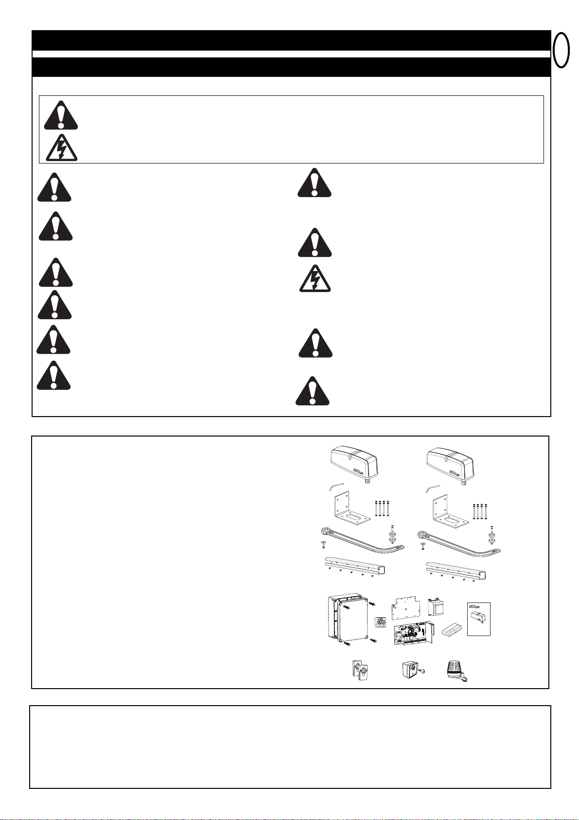
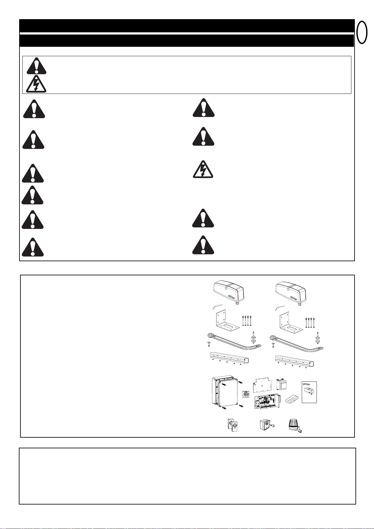
CARTON CONTENTS HC624
Drive motors 2x
Release key 2x
Box for control 1x
Cover for box 1x
Hinges for box 4x
Control 1x
Transformer 1x
Baseplate For Transformer 1x
Remote control 1-2x*
Radio receiver 1
Radio module 1x
Hardwarebag For Box 1x
Pillar fittings 2x
Gate fittings 2x
Door arm 2x
Hardwarebag 1x
Instructions 1x
Flashing light 1x
Key switch 1x
Photocells 1x
* depending on model resp. available as optional accessory
INSTALLATION CHECKLIST - PREPARATIONS
Check the carton contents and read the instructions carefully. Make sure your gate equipment operates perfectly. The gate must run evenly and
smoothly and must not stick at any point. Remember that the ground level may be several centimeters higher in winter. The gate must be stable
and as free of backlash in order to prevent any unwanted movement. The easier the gate movement the less power is needed by the motor.
Write down any materials you still need and obtain them before starting to install. Heavy-duty plugs, bolts, gate stops, cables, distribution boxes,
tools, etc.
PLEASE START BY READING THESE IMPORTANT SAFETY RULES • SAVE THESE INSTRUCTIONS
This safety alert symbol means "Caution" - failure to comply with such an instruction involves risk of personal injury or
damage to property. Please read these warnings carefully.
This gate drive mechanism is designed and tested to offer appropriately safe service provided it is installed and operated in
strict accordance with the following safety rules.
Incorrect installation and/or failure to comply with the following instructions may result in serious personal injury or property
damage.
Installation and wiring must be in compliance with
your local building and electrical installation codes.
Power cables must only be connected to a properly
earthed supply.
Any entrapment possibility by the moving wing
between wing & walls must be secured with safety
edges or IR-sensors.
Disconnect electric power to the system before making
repairs or removing covers.
A disconnecting device must be provided in the
permanently-wired installation to guarantee all-pole
disconnection by means of a switch (at least 3mm
contact gap) or by a separate fuse.
When using tools and small parts to install or carry
out repair work on a gate exercise caution and do not
wear rings, watches or loose clothing.
Make sure that people who install, maintain or operate
the gate drive and/or the control board are qualified and
follow these instructions.
Keep these instructions in a safe place so that you can
refer to them quickly when you need to.
Please remove any locks fitted to the gate in order to
prevent damage to the gate.
Frequently examine the installation for imbalance and
signs of wear or damage to cables, hardware and
mountings. Do not use if repair or adjustment is
necessary. Gates which stick or jam must be repaired
immediately. Employ a qualified technician to repair the
gate, never attempt to repair it yourself.
Keep additional accessories away from children. Do not
allow children to play with pushbuttons or remote controls.
A gate can cause serious injuries as it closes.
After the installation a final test of the full function of
the system and the full function of the safety devices
must be done.
The full protection against potential squeeze or
entrapment must work direct when the drive arms are
installed.
This drive cannot be used with a gate incorporating a
wicket door unless the drive cannot be operated with
the wicket door open.
IMPORTANT FITTING AND OPERATING INSTRUCTIONS
WARNING / ATTENTION
TM
T
M
T
M
T
M
T
M
T
M
T
M
T
M
Page 3
en-2
BEFORE YOU BEGIN: The HC624 is suitable for use with wide pillars, up to about 29cm in width.Width of doorwing must comply with chart.
The maximum recommended opening angle of the gate is 105 degrees. Ensure that ample space is available next to the drive for the arms and
assembly. Gates exposed to a high wind load must be fixed with an electric lock for additional protection. Gate stops must be installed
There are many important factors when deciding on the correct motor. Assuming a well functioning gate, the initial force is the most difficult
moment. When the gate is moving it generally requires a considerably smaller amount of force.
Gate Size: Gate size is an important factor. Wind can slow down gate or distort it, leading to higher amount of required force.
Gate weight: Specification of gate weight represents only a rough parameter, which can vary according to actual demand. Operation is
important.
Influence of temperature: Low outdoor temperatures can impede or even prevent starting torque (ground deformation etc.). High outdoor
temperatures can lead to premature initiation of temperature protection (approx. 135°)
Attention: Motors are not designed to run continuously (continuous operation). The motor warms up and can reach a temperature at which it
shuts down until operating temperature is reached again. Outside temperature and gate represent important parameters for actual operating
duration.
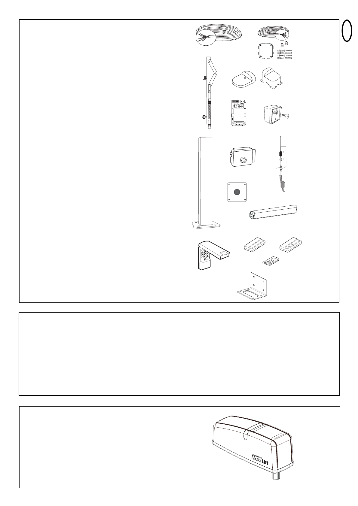
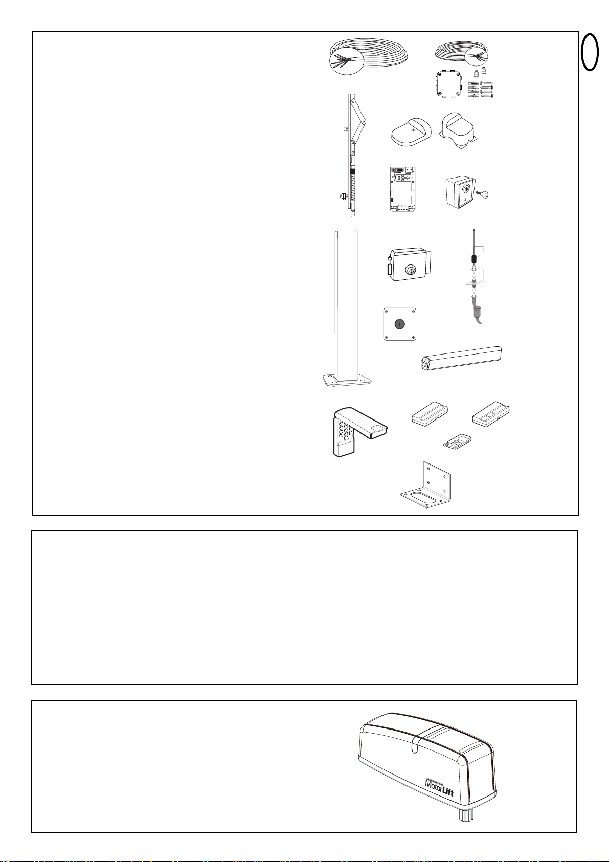
AVAILABLE INSTALLATION ACCESSORIES
1. 041ASWG-0482-50 50m roll of installation cable, 6-pole for
outdoor use, Laying possible without
cable duct with the identical wire colours
as motor
2. LA400-JB40E Kit for cable extension of one installation
unit. Consists of 12m of cable 6-pole with
identical colours, distribution box IP65,
cable screw joints and fastening material
3. E-lock 203285 (12Volts)
4. Transformer for E-lock 207399
5. Floor locking 203339 (in combination with E-lock)
6. Stops for wings 203315 (standard) and 203322
(high)
7. Safety edge 600046 2.5m set of safety edge
(profile & rail)
600053 20m of rubber profile (small)
600077 20m of mounting rail
600077-1 2m of mounting rail
600060 Assembly pack is required for
each safety edge
8. IR Sensor stand 600008 single, height 530mm
9. Emergency Stop switch 600084 plastic enclosure, IP65
10. Keyswitch 100034 2-Function, flush-mount
100041 2-Function, surface-mount
11. External Antenna 041ASWG-ANT
12. Remote Controls 84330EML 1-channel
84333EML 3-channel
84335EML 3-channel, mini
13. Wireless keypad 8747EML
14. Base plate standard ART-7
TECHNICAL DATA:
Motor voltage 24V
Nominal power 10W
Max. power 40W
Current nom. 0,5A
Current max. 1,3A
Torque max. 200Nm
Opening time 90° ~16 sec.
Cycles/h ~ 20
Consecutive cycles max. 8
Operating temperature -20°C - +55°C
Degree of protection IP44
Weight 8kg
2
3
4
5
6
7
8
9
10
11
12
13
1
14
3x
TM
T
M
Page 4
en-3
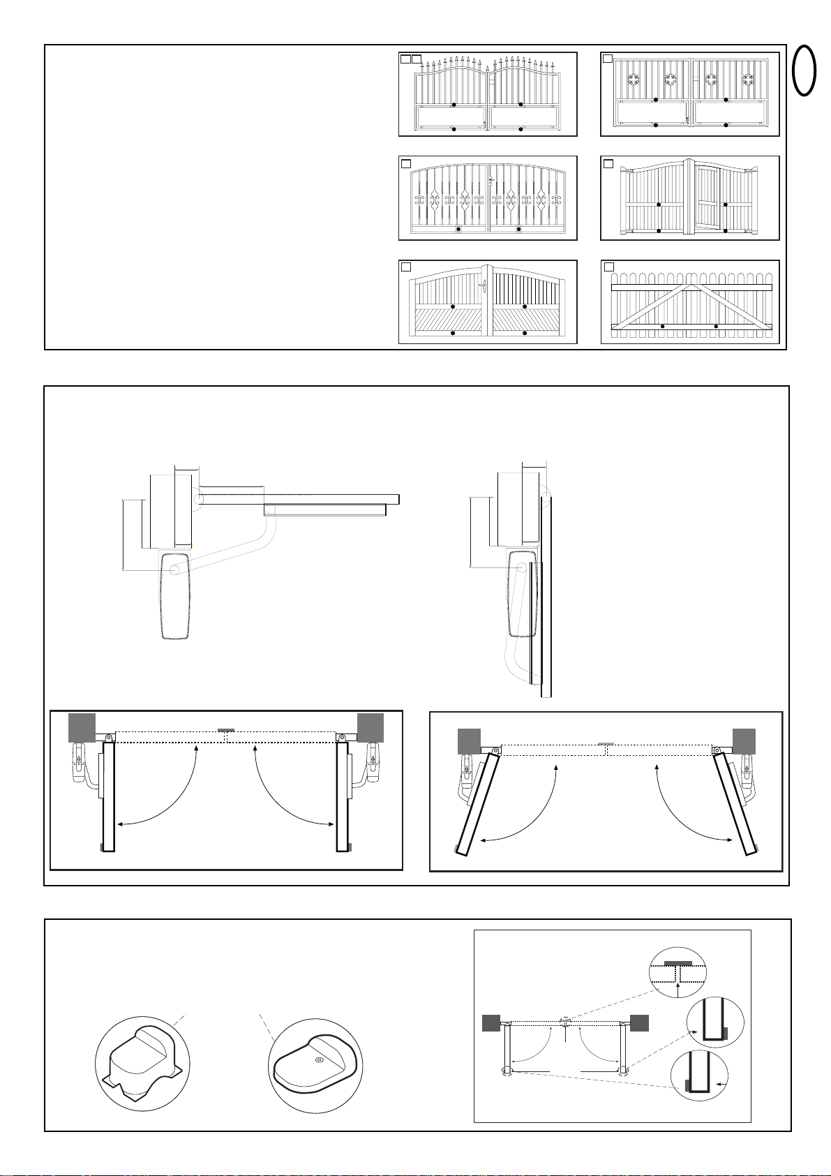
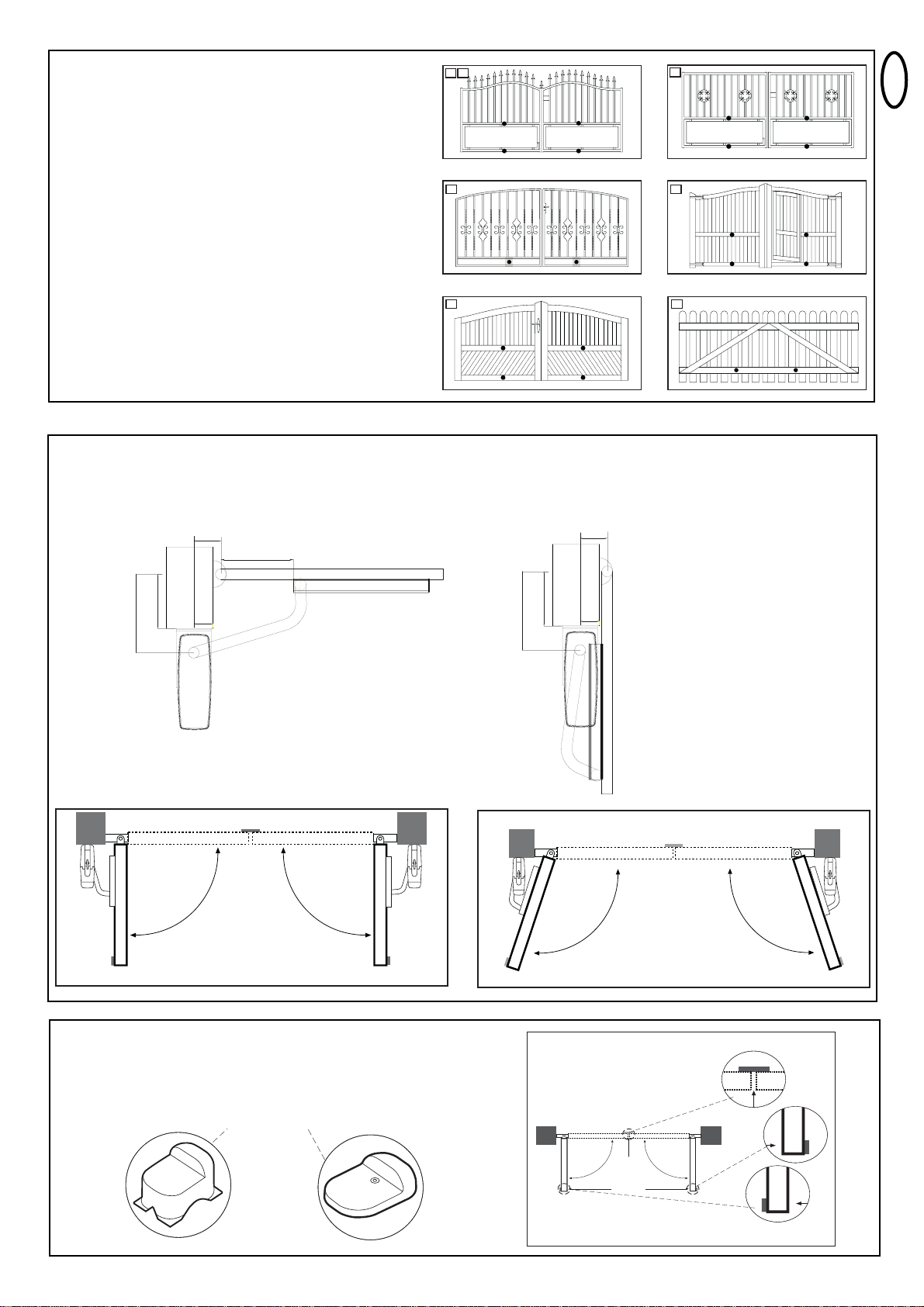
GATE TYPES
The location of the motor installation depends on the type of gate.
If the gate stop is on the floor the motor should also be installed as
low as possible in order for the gate not to be distorted. Only use
frame elements for fastening.With steel gates the fittings should be
fastened to the main frame. If you are not sure about the stability of
the frame in question then reinforce it.
With wooden gates the frame has to be drilled through
completelywhere the fittings are to be fastened. Attaching a plate
from the outside is recommended in order to prevent fastening from
becoming loose. Thin wooden gates must be reinforced additionally
as they do not withstand the strain otherwise.
GATE CONFIGURATION
The ART is suitable for use with wide pillars, up to about 29cm in width. The amount of room around the pier affects the opening angle and the
position of the arms.
GATE STOPS
A SWING GATE NEEDS A FIXED GATE STOP IN BOTH THE OPEN AND
CLOSE POSITIONS. Gate stops save wear and tear on the motor, gate and
fittings. Operating a gate without fixed limit stops results in poor performance. It is
often dangerous, leads to premature wear and voids your warranty!
Max gate width/weight
Max gate height
2,5m per wing / 150Kg
2,0m per wing / 200Kg
1,5m per wing / 250Kg
1,5m
Specifications calculated without windload
2 A
B
C D
E F
290
200
max.
100
100
267
200
70
o
90
o
90
290
70
max.
105° 105°
0
90
0
90
Page 5
en-4
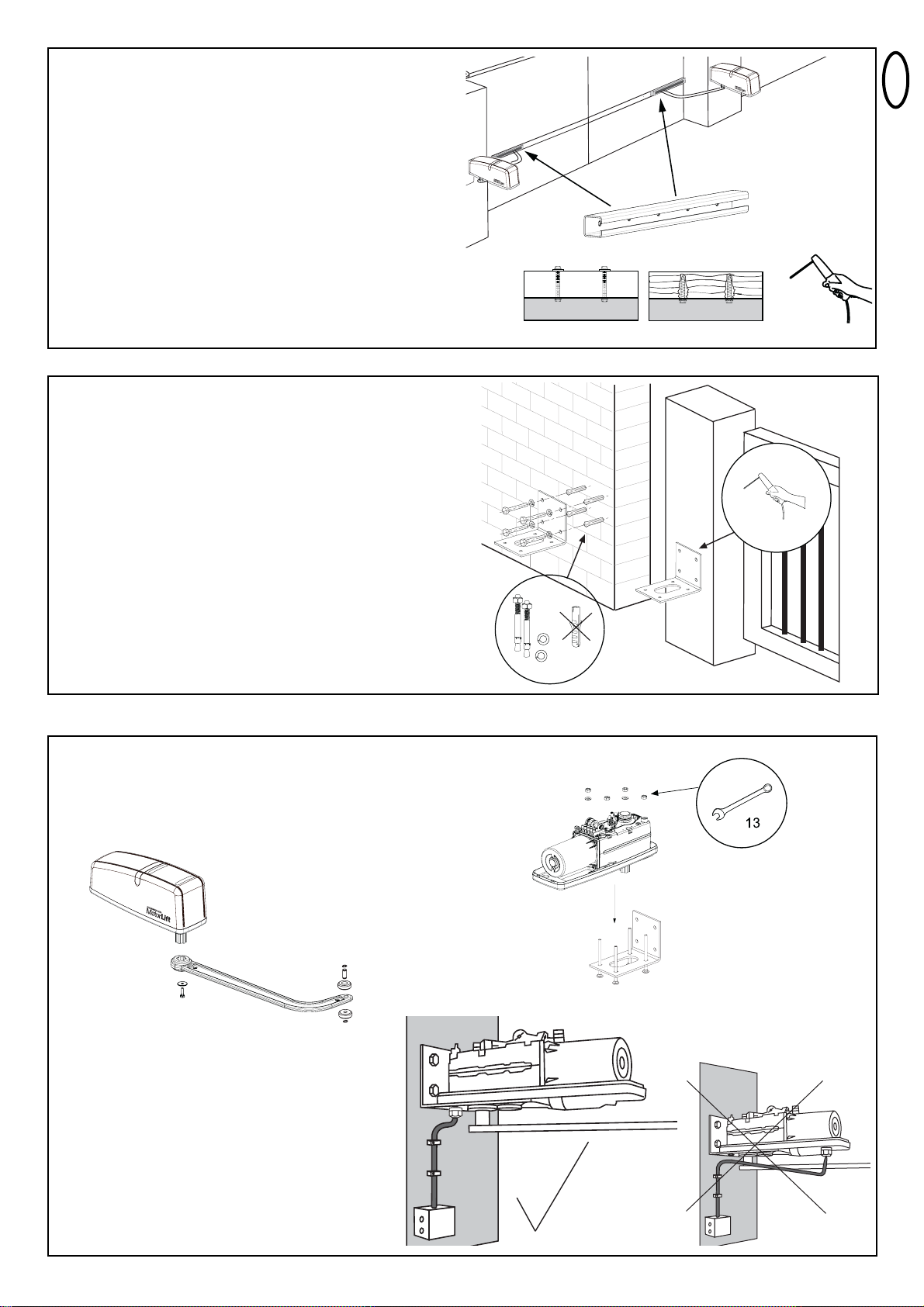
BASE PLATE
Select and mark the mounting height on the pier.
Finding the right mounting position. Mount the drive on the pier and
attach it to the gate. The drive exerts a great amount of force on the
pier. A steel pier will provide the most stability. Welding the supplied
hinge plate directly on to the pier will generally provide enough room
for mount. In the case of thick brick or concrete pillars, the hinge
plate should be welded onto a support plate, that is mounted in such
a way that the plugs cannot work loose. Adhesive shear connectors
are better than steel or plastic wedge anchors for this purpose. A
threaded rod is then mounted into the masonry with a stress free
adhesive seal. A watertight distribution unit should be mounted on
the pier next to the hinge plate. The feed cable for the wing gate
opener is led into this unit from underneath.
GATE FITTING
With steel gate the fastenings should either be welded on or drilled
through completely. If drilling then attach large washers or a plate to
the back of the frame.With wooden gates the gate frame has to be
drilled through completely where the fittings are to be fastened.
Attach reinforcement plate on the outside and inside of the gate in
order to prevent wood from giving and the connection to become
loose.
Thin wooden gates without metal frame must be reinforced
additionally, as they do not withstand the strain otherwise.
Before installing the gate fitting, check if you measured the right
position for it. Adjust if needed.
Attach gate fitting with a c-clamp or mark its designated position.
To compare, open the gate to designated OPEN position.
Now finally mont gate fitting.
Mount operator and run cable the right way
Once the base plate has been mounted, the drive can then be fitted.
The drives can be used left or right without requiring conversion. For
the purposes of fitting the drive, the lock screws need to be reinserted and tightened up.
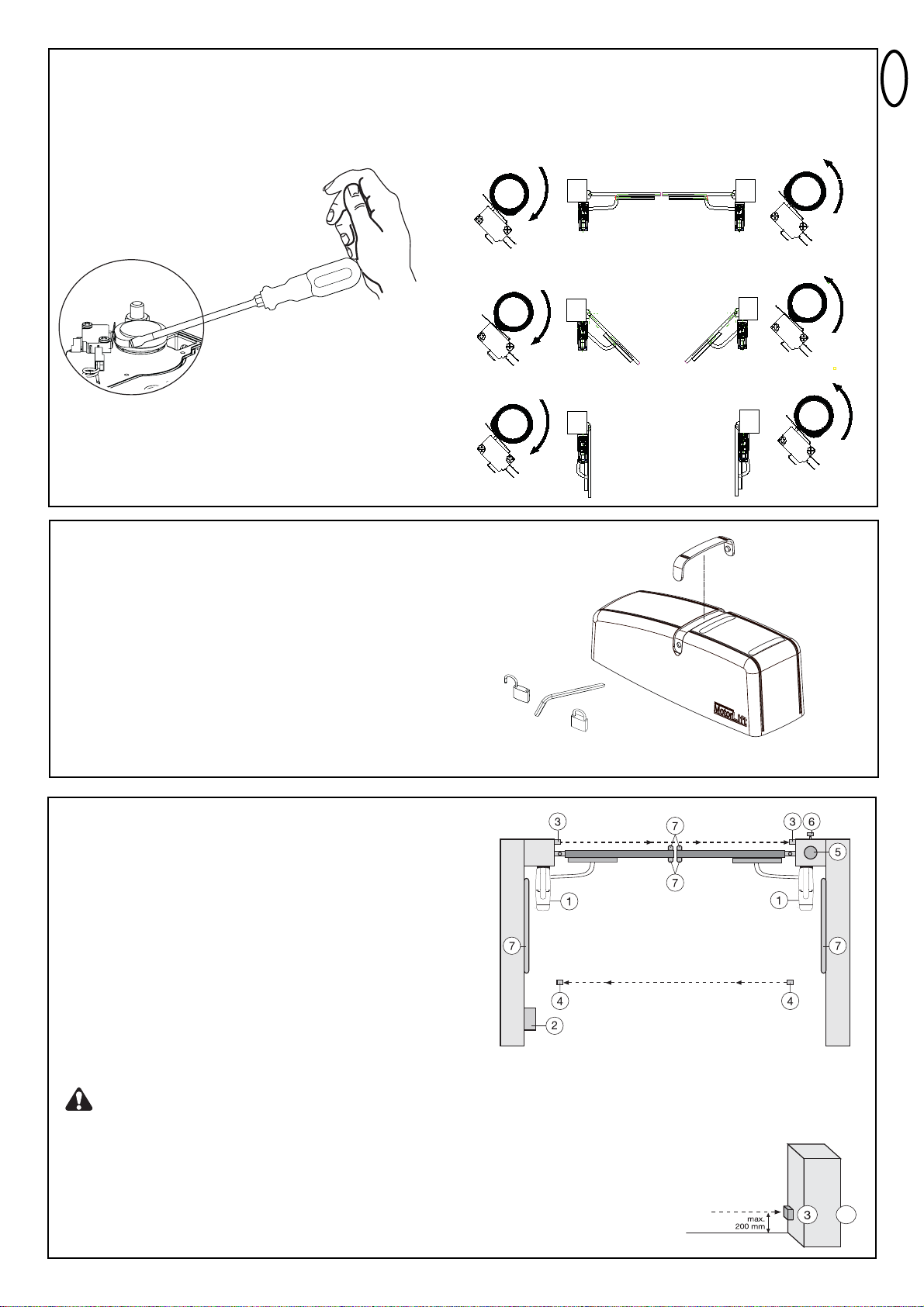
Several openings for the cable have been pre-punched in the
base and need only be broken through, as required. The
drive must be standing on a solid surface for the purposes of
breaking the holes through to prevent the PVC base plate
from breaking. A small, flat screwdriver should be used for
breaking the holes through. For this purpose, tap on the
screwdriver handle with the palm of the hand from the inside.
Repeat this as necessary at several points on the pre-marked
circle. The pre-punched area can then be easily removed and
the strain relief supplied as standard fitted in its place.
T
M
TM
T
M
TM
T
M
TM
Page 6
en-5
RELEASE/ MANUAL GATE OPERATION
The release lock for the casing is located under the rubber waterproof
cover. Use the socket spanner supplied in the hardware bag to lift the
cover up. The release key located beneath the hood should be
inserted into the side openings and turned approx. 180 degrees until
it cannot turn any further. The drive has now been released. To reengage it, the key should be turned back to its original position.
Take care when unlatching the drive for manual operation. The
door leaf can move in an uncontrolled way, especially if it is
defective and not properly balanced.
Before initial operation check if operator does not come in contact
with the gate in the fully OPEN position.
SWITCHES, CAMS AND RIGHT ADJUSTMENT
There is a small switch operated by a cam under the operator’s
cover. The cam rotates simultaneously to the operator and pushes
the switch temporarily. The cam can be adjusted (rotated). (Tight)
Deinstallation is not required.
Use pliers or a big screwdriver to adjust (see picture).
RIGHT ADJUSTMENT
Gate closed: switch free
Gate at approx. 45°: switch fully pushed (cam operates
switch)
Gate open: switch free
TYPICAL CONFIGURATION OF A UNIT:
1. Motor
2. Control board
3. Photocell (active for closing), max. height 200 mm
First photocell.
4. photocell (active for opening and closing), max. height 200 mm
Second photocell (optional).
5. Flashing light (optional)
Important visual information on the movement of the gate.
6. Key-operated switch or wireless keypad (optional)
Is mounted on the outside. The gate is opened by key or by
entering a number.
7. Contact strip (optional)
Safeguards the gate on being touched. Contact strips can be
mounted on the gate or on the pillars. If required, contact strips
must be mounted at a height of up to 2.5m.
The control board complies with the latest EU
guidelines. One of these guidelines specifies that the
closing forces at the gate edge must not exceed 400 N (40 kg) for
the last 500 mm before the door is CLOSED. Above 500 mm, the
maximum force at the gate edge must not exceed 1400 N (140
kg). If this cannot be ensured, a contact strip must be mounted on
the gate at a height up to 2.5 m or on the pillar on the opposite
side (EN12453).
Note: The listed accessories on page 2 are especially suited for the professional
installation of a gate system.
4
+
Page 7
en-6
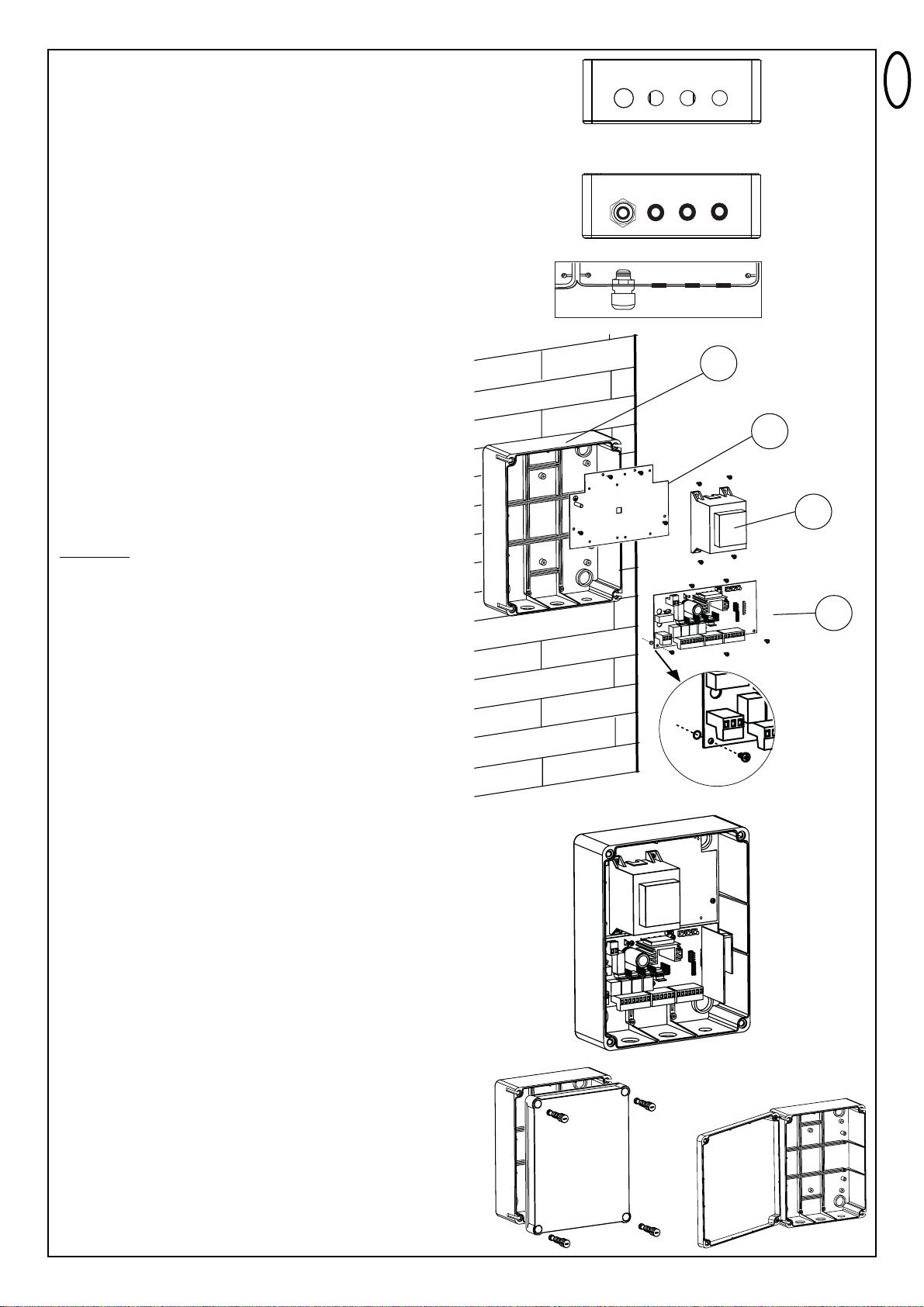
INSTALLATION OF CONTROL BOX
The control consists of several components which are fitted together
and are screwed into the box. Precision is important.
Complete the electrical installation (wiring, supply etc.) before turning
your attention to this point.
Find the following parts in the control box:
- Remote control 1-2x*
- Exterior installation box 1
- Cover for box 1
- Control 1
- Transformer 1
- Baseplate for transformer 1
- Radio receiver 1
- Radio module 1
- Cable bushing large 1
- Cable bushing small 1
- Flat washer 5
- Screws 3,5x 9,5 mm 17
* depending on model resp. available as optional accessory
PREPARING THE CONTROL BOX
Open the 4 pre-cut holes at the bottom of the casing with a
screwdriver or a similar device.
Attach large cable bushing on the left then the rest as shown in
picture.
Humidity and water destroy the control. All openings and cable
bushings must be sealed against water (waterproof). The control box
with the motor control is to be mounted with the cable bushings
facing down.
RECOMMENDED PROCEDURE:
A. Fasten control box of casing to wall, after previously measuring
required distances and establishing correct position of drill-holes.
(Hardware not included)
B. Fasten baseplate for transformer in casing. (Screws 3.5 x 9.5mm)
C. Fasten transformer on to baseplate; do this using 4 screws
( Screws 3.5 x 9.5mm). On the right hand side of transformer
there is sufficient space for a second transformer( Screws 3.5 x
9.5mm), which can control locking of a 12Volts E Lock.
(accessories).
Attach short earthing cable (yellow/green) to the plate using a
screw and a washer.
D. Attach logic board underneath baseplate; do this using 5 screws
and fasten in the box at the marked positions. Before that pull all
plug ins from their sockets. A small bag contains jumpers for the
control. These might be needed later on individual settings in the
controls’ programming. (refer to JUMPERS)
Put the 4 large closure screws of the box through cover of the
box. Fasten 2 of them (left or right) approx 2cm into the box. After
that the cover may be opened to the side.
Close box on a trial basis turning the screws all the way in. If the
lid does not close completely, then the box is not fitted to the wall
evenly and is therefore distorted. This must be corrected. It is very
important for the box to be waterproof once closed.
A
B
C
D
X 5
Page 8
+
-
en-7
TECHNICAL DATA OF MOTOR CONTROL:
Voltage 230VAC
Transformer 230/24VAC minimum60VA
Output motor 24VDC max.
Supply accessories 24VDC - 100mA
Operating temperature -20°C - +55°C
Degree of protection IP54
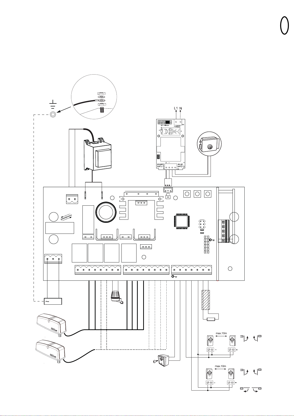
WIRING OF CONTROL / SUMMARY
a) start with still dead 230Volts supply cable on the left side of the box.
b) Attach cable eye to ground wire. Then connect ground wire to base
plate with washer and nut (exactly as shown in picture detail).
Connect all other cables to control.
Attention:Check repeatedly that cable colours are connected correctly
to motor. Otherwise motor might be damaged or will not operate
properly. Pay special attention when using distribution boxes.
We recommend the following accessories: LA400-JB40E Kit for
cable extension of one installation unit. Consists of 12m of
cable 6-pole with identical colours, distribution box IP65,cable screw
joints and fastening material
PE
LN
230VAC
PE
TRANSFORMER
250V/2A
T
M
T
M
230VAC
30VDC
INPUT
24VAC
250V/2A
MOTOR
MASTER
RED
SECOND
BLUE
MOTOR
RED
24V/150mA
/ LAMP
BLUE
-
+
BRN GRN WHT YEL
MASTER
BRN GRN WHT YEL
SECOND
P1 P2 P3
PHOTO
COM
1 2
COM
1/2 MOTOR
STOP/8.2K
OPEN / PED
JP1
JP2
STOP/8.2K
PHO2
PHO1
LEARN
DIAGNOSTIC
STOP/*
8.2
Ω
8.2
Ω
Ω
RADIO
801719
T
M
T
M
+
+
+
+
+
Page 9
en-8
DESCRIPTION OF PUSH BUTTONS
P1 button to program “simple” mode
P2 button to program “individual” mode
P3 button to program “Timer to close”
Description of LED’s (light-emitting diode)
Description Colour Function
STOP/8.2KOhms green monitors emergency switch
or safety edge
ON: blocks control board
OFF: OK
“Key symbol” red key switch
ON: key switch is operating
OFF: key switch is not
operating
PHO2 red Photocells 2
ON: OK (active)
OFF: no photocell fitted
PHO1 red Photocells 1
ON: OK (active)
OFF: no photocell fitted
LEARN yellow learn mode indication
ON: learn mode active
OFF: learn mode inactive
DIAGNOSTIC red diagnosis mode
Refer to FAQ’s
DESCRIPTION FUNCTION
L Connector L 230V supply
N Connector N 230V supply
Battery Connector for a battery kit +/-
475E + 041ADBL-0115
Motor MASTER motor 1 (master opens first)
Motor SECOND motor 2 (Second opens second)
24V/150mA Flashing light (accessory)
MASTER Motor1
BRN brown cable
GRN green cable
WHT white cable
YEL yellow cable
SECOND Motor2
BRN brown cable
GRN green cable
WHT white cable
YEL yellow cable
“Key symbol” key switch
COM negative pole
PHOTO1 Photocells 1
PHOTO2 Photocells 2
COM negative pole
STOP 8.2KOhms connector for emergency switch or
safety edge with 8.2KOhms
RADIO connection for 801719 radio receiver
E-lock symbol connection for E-lock control board
INPUT 24VAC 24V power input from transformer.
Can be connected with any polarity.
Transformer 230VAC 230V supply to transformer. Can be
connected with any polarity.
250V/2A Fuse 250V/2A (2x included)
Only modify settings when control bord
is disconnected. Otherwise modifications will
not be accepted!!!
Page 10
en-9
COM
PHOTO
1 2
COM
STOP/*
8.2
Ω
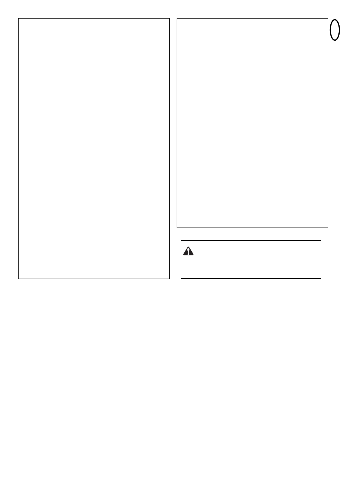
KEY SWITCH (OPTIONAL)
The system can be operated by key switch. It is possible to operate
only 1 wing or two wings. This depends on how the JUMPERS are
used (connectors: key symbol and COM)
COM
PHOTO
1 2
COM
STOP/*
8.2
Ω
COM
PHOTO
1 2
COM
STOP/*
8.2
Ω
Ω
8.2
Ω
8.2
+
+
+
+
+
E-LOCK (OPTIONAL)
The control board allows the use of a 12V E-lock. (instructions
included with E-lock).
A support board must be connected for the E-lock on the main
board.
Attach support board next to the transformer on to the baseplate
using screws.
Open its casing and make all necessary electrical wiring.
Plug support board in to where the E-lock symbol is depicted.
PHOTOCELLS (OPTIONAL)
The photocells are for safeguarding the gate and must be used. The
fitting location depends on the gate’s design. EN12453 specifies that a
pair of photocells must be installed at a height of 200 mm and activated
to “Close”. The photocells consist of a transmitter and a receiver and
must be opposite each other. The photocell is mounted on the wall
using small screws and wall plugs. To enable the “Automatic Closing”
function, the Chamberlain failsafe photocell must be installed. The
Chamberlain failsafe system (2-cable system) has small LEDs (light)
that can be seen from the outside on both sides to indicate the status
of the photocell.
Diagnosis at the Chamberlain failsafe photocell
LED constant = OK
LED flashes = photocell disables control board
LED off = no current, incorrect connection or polarity
Diagnosis on the control board
LED off = OK no photocell connected
LED on constantly = OK
LED flashes = photocell disables control board
Connection between 1 & COM will give:
ignored when gate is opening, when closing if beam is blocked gate
stops then reopens (does not matter when beam is unblocked).
Connection between 2 & COM will give:
when gate is opening block beam gate stops when you un-block beam
gate caries on opening.
When gate is closing block beam gate stops un-block beam gate
reopens.
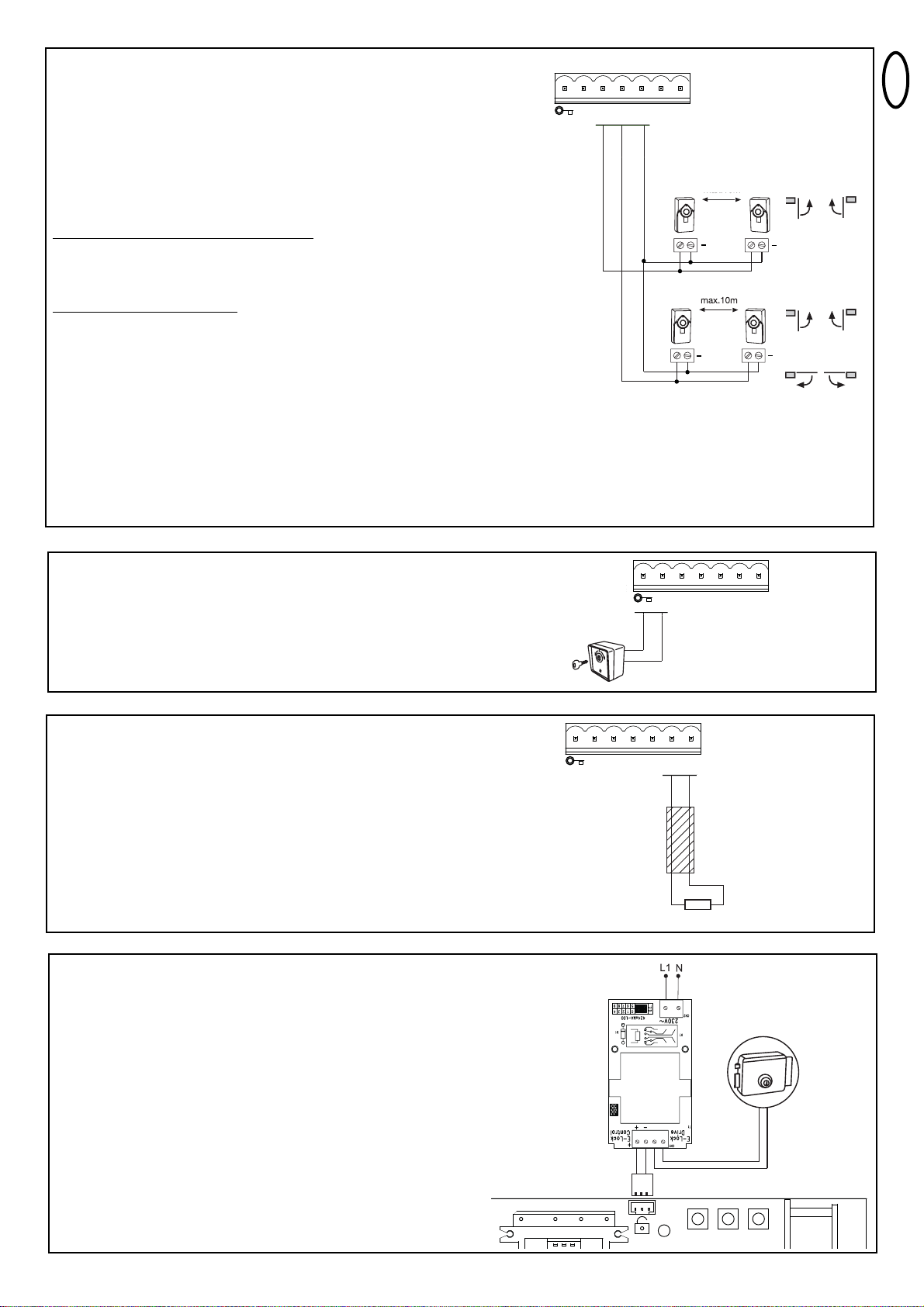
SAFETY EDGE (OPTIONAL)
A safety edge working according to the 8.2 kilo ohm principle can be
connected to the control board, i.e. a 8.2 kilo ohm test resistor is
attached to the end of the safety edge. It ensures that the electric
circuit is monitored permanently. The control board is supplied with
an 8.2 kilo ohm resistor installed. Several safety edges are
connected in series.
Cable cross-section: 0.5 mm2or more.
P1 P2 P3
Page 11
en-10
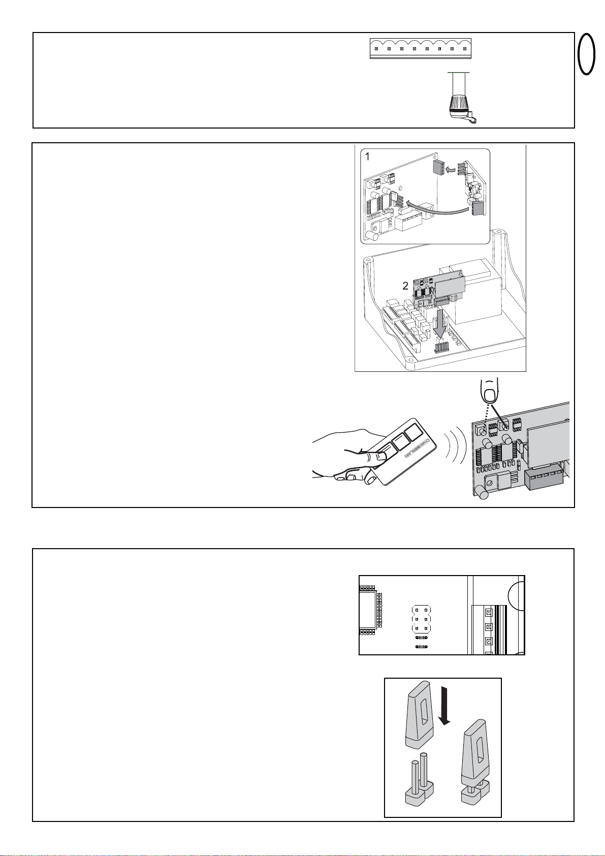
RADIO
There are two small cartons. One of the cartons contains the receiver,
which stores remote control codes. The other one contains the radio
module, which receives the radio signal.
1. connect the smaller radio module with the receiver
Make sure all pins are properly engaged
2. connect the receiver with the control board
Antenna: The receiver includes a short antenna. It should
not come in contact with any cable and should not be rolled
up. It is possible to install an external antenna which
enlarges the operating distance of the remote control
(optional accessory).
PROGRAM / DELETE REMOTE CONTROLS
The receiver has two channels CH1 and CH2. Using the different
channels enables the opening of one wing resp. both wings. For
example, if CH1 receives the code from the remote control only one
wing will open. Choosing a different button on the remote control in
combination with CH2 will cause both wings to open.
In order to store a code press a previously selected button on the
remote control while simultaneously pressing the learn-buttons CH1
or CH2 of the receiver. Repeat for all remote controls.
A maximum of 12 remote controls can be programmed to each
channel.
Note: Make sure not to pogramm the same remote button to CH1
and CH2, otherwise the gate may work improperly. Redo
programming if required.
DELETE
Press learn-buttons (CH1 or CH2) for approx. 10 seconds until LED
goes out. All codes programmed to this channel are deleted.
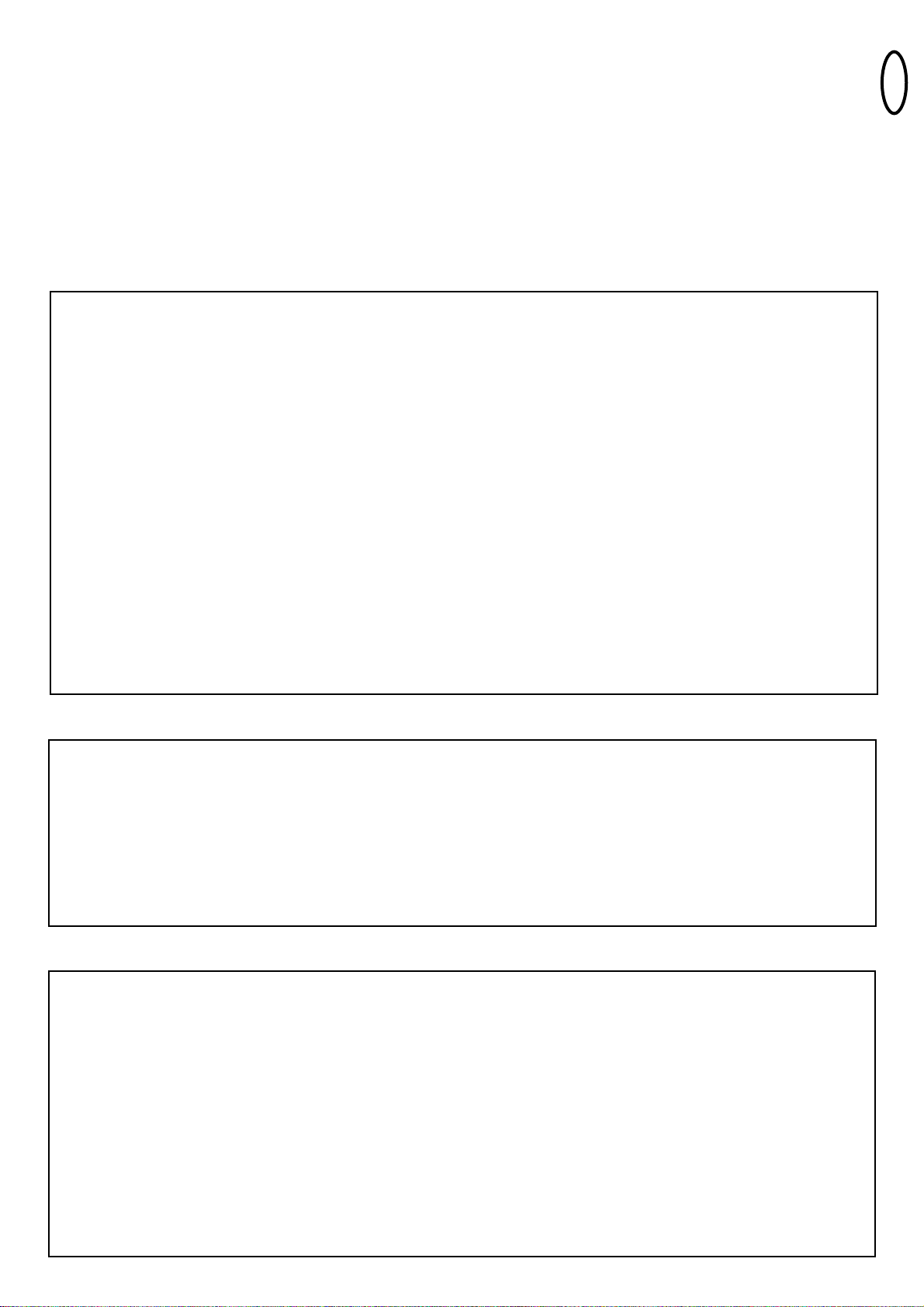
1 / 2 Motor
1 or 2 motors are connected to the control board.
FREE: both motors connected
LINKED: only one motor connected
STOP / 8.2 KOhms
Defines if connector STOP / 8.2 KOhms is used for an emergency
stop switch or for a safety edge. The emergency stop switch stops
any movement of the system immediately. The safety edge causes
the wings to reverse for one second.
FREE: Factory setting is for 8.2 KOhms. In this case safety edge
must be installed or a 8.2 KOhms resistor must be
connected.
LINKED: used for emergency stop switch, in this case the pre-
installed resistor has to be removed from terminals and
replaced by a suitable switch or terminals have to be
bridged.
Open / Ped
Defines if key switch operates only one wing (Master) or both wings
FREE: only one wing (Master)
LINKED: both wings
JUMPERS
30VDC
MOTOR
MASTER
+
-
MOTOR
SECOND
24V/150mA
BR
/ LAMP
+
-
RED
BLUE
FLASHING LAMP (OPTIONAL)
A flashing lamp can be connected to the control board. It warns
when the gate is being moved. The flashing light should be fitted as
high as possible and in good clear view. The control board emits a
constant signal that the lamp converts to a flashing signal.
Cable cross-section: 0.5 mm2or more.
Voltage: 24 V DC
ª
1/2 MOTOR
STOP/8.2K
Ω
OPEN / PED
JP1
JP2
Page 12
en-11
INITIAL OPERATION
BASIC SETTING
Proceed step by step. If you are not sure, start again at the beginning. Take sufficient time to make these settings.
1. Are all components required for operation connected? Motors, photocells, safety contact strip, stop switch.
2. Make sure that nobody is present in the range of the gates.
3. Check/Adjustment/Correction of cams on both motors
Gate closed: switch free
Gate at approx. 45°: switch fully pushed (cam operates switch)
Gate open: switch free
(for adjustment refer to mechanical installation)
PROGRAMMING TRAVEL DISTANCES “ADVANCED”
NOTE: In this mode P1 must be pressed 9 times. With every time the button is pressed a position (time) is stored. (This allows
programming of SOFT-STOP (slow travel) in order to adjust to application. Long or short phases of SOFT-STOP are possible.
1. Both wings must be closed.
2. Press P1 and P2 for approx.5-6 seconds until wing / motor 1 starts opening.Release buttons!!!
3. Press P1 again. SOFT-STOP for wing / motor 1 in OPEN direction starts at this point.
4. Press P1 again when OPEN position is reached.Now wing / motor 2 starts automatically to open.
5. Press P1 again. SOFT-STOP for wing / motor 2 in OPEN direction begins at this point.
6. Press P1 again when OPEN position is reached. Now wing / motor 2 starts closing automatically.
7. Press P1 again. SOFT-STOP for wing / motor 2 in CLOSE direction begins at this point.
8. Press P1 again when CLOSE position is reached. Now wing / motor 1 starts automatically to close.
9. Press P1 again. SOFT-STOP for wing / motor 1 in CLOSE direction begins at this point.
10. Press P1 again when CLOSE position is reached.
Done!
BASIC SETTING:
1. Press buttons P1, P2 and P3 simultaneously for approx. 2-3 seconds until yellow LED flashes.
2. Monitor the gate. Press and hold P1 for 1-2 seconds. The wing with motor 1 opens. If motor 1 closes, it is wired incorrectly and
the red and blue wires of the motor cable must be inverted. (Caution: Disconnect Power!)
Repeat steps 1 and 2. Leave gate/s in partially open position.
NOTE: General operation – if you release the button, the gate will immediately stop. By pressing the button again the gate will
move in the opposite direction until you release the button, and so on.
3. Press and hold P2 for 1-2 seconds. The wing with motor 2 must open. (Do not open gate completely, only short distances.)
If motor 2 closes, it is wired incorrectly and the red and blue wires of the motor cable must be inverted.
(Caution: Disconnect Power!)
Repeat steps 1 and 2. Leave gate/s in partially open position.
NOTE: The control board is active for this manual setting mode for approx. 20 seconds. If necessary, start again by pressing P1,
P2 and P3 simultaneously.
Now check the following:
1. If both operators connected open both wings completely.
2. Both wings must open completely. Do not open the wings too far! A gate stop in OPEN position is required.
Caution: Gate must not come in contact with operator (i.e. when operator has been released for manual operation)
Wait until learn-LED goes out (20 seconds after a button was pressed).
PROGRAMMING TRAVEL DISTANCES “SIMPLE I”
NOTE: only with stops in OPEN and CLOSE position
1. Wings must be closed
2. Press P1 until wing / motor 1 starts opening (learn-LED flashes resp. glows)
Automatic programming starts (slow travel)
Wing 1 moves to the stop in OPEN position
Wing 2 moves to the stop in OPEN position
Then wing 2 moves to the stop in CLOSE position.
Then wing 1 moves to the stop in CLOSE position.
When the learn-LED goes out the programming has finished.
Page 13
en-12
NOTE: If one wing reaches a stop and button P1 is not pressed, then the motor moves towards the stop and stores this position
automatically.
COMPLETION OF INSTALLATION / PROGRAMMING
Once the travel distances are programmed, the remote controls can be programmed as well.
(Refer to PROGRAMM / DELETE REMOTE CONTROLS).
1. Operate the gate with a remote control or with a connected switch and monitor the direction. Close the gate again WITHOUT
any interuptions.
2. If all adjustments are done, check operation of photocells, switch, flashing light, remotes, accessories, etc.
3. Advise people using the gate with regard to gate operation, safety functions and how to release the gate in order to operate it
manually.
TIMER TO CLOSE
NOTE: Only possible with connected photocells (1 + COM). Time frames from 2 seconds up to 120 seconds are possible.
Activate:
1. Press and hold P2 until yellow LED starts flashing
2. Now count the time you wish to program
3. Press P2 again. Done!
Deactivate:
1. Press and hold P2 until yellow LED starts flashing.
2. Press P3. Yellow LED goes out. Done!
TORQUE OF MOTOR
Thrust of the motor is set automatically while programming
the travel distance. Thrust can only be modified by
programming the travel distance again. If gate movement is
impeded by weather or changes to the installation (rust or
inappropriate lubrication) it may have to be repaired.
The control board complies with the latest EU
guidelines. One of these guidelines specifies that the
closing forces at the gate edge must not exceed 400 N (40 kg) for
the last 500 mm before the door is CLOSED. Above 500 mm, the
maximum force at the gate edge must not exceed 1400 N (140 kg). If
this cannot be ensured, a contact strip must be mounted on the gate
at a height up to 2.5 m or on the pillar on the opposite side
(EN12453).
Page 14

en-13
Indication Description Remedy
1x blinking Motor 1 has insufficient connection to control board Green or white cable not wired or badly connected Check
terminals precisely. Consider wire lengths
2x blinking Motor 2 has insufficient connection to control board Refer to 1x blinking
3x blinking Limits for motor 2 have not been accepted A: Open gate wide enough when programming the travel. Make
A: After or during first travel: operator did not open sure cam passes all 3 states (switch free, pushed, free)
open wide enough to meet not meet passpoint B: Check terminals precisely. Consider wire lengths
(cam did not operate switch)
B: Motorcables have insufficient connection to contol board
Yellow or white cable not wired or badly connected
4x blinking Limits for motor 1 have not been accepted Refer to 3x blinking
5x blinking Travel has not been programmed Repeat programming travel
The process of programming has been interrupted
6x blinking Force to operate the gate is too high
A: Gate is out of order A: Repair gate
B: Gate is rough-running B: Check if gate can be easily moved
C: Gate stopped through windload C: Do not operate gate by windstorm
D: Reprogram travel to achieve sufficient level of fo
7x blinking Photocells 1 block installation
A: Object blocks photocells A: Remove object
B: Alignment of the lenses is incorrect B: Check alignment
C: Power supply to photocells is insufficient C: Check cable widths and contacts
8x blinking Photocells 2 block installation Refer to 7x blinking
9x blinking Emergency stop switch blocks installation A: Check wiring
B: Check basic setting of control board (Jumpers)
10xblinking Safety edge blocks installation
A: Object obstructs safety edge A: Remove object
B: Defective safety edge B: Check wiring. Check resistor 8.2KOhms
C: Power too low or broken wire in supply C: Check basic setting of control board (Jumpers)
11xblinking Power supply to control board is too low
A: Defective supply 230V or malfunctioning contact A: Check electric contact
B: Broken wire in supply cable (copper cable) B: Check by electrician
C: The battery (accessory) to operate the gate whilst C: Allow battery to charge 24 hours
power failure is dead.
12xblinking EEPROM Fault
Power up failed Replace contol board
INDICATION OF THE DIAGNOSIS LED
Page 15

en-14
The gate opener doesn’t respond at all; no LED is
on.
Possibly power failure.
1. Check conductor and zero conductor.
2. Check house fusing.
Immediately after the gate has started moving, it
stops and reverses.
Obstacle in area of gate.
Check area of gate for objects
If there is no obstacle, make another initial
operation to ensure the force will be learned
again.
The gate opener does not open the gate fully. 1. Are the post dimensions A+B correct?
2. Has the travel of the controller been set
correctly?
1. Check A+B dimensions.
2. Reprogram if required
Gate can only be opened
1.photocell blocks 1.Function and connection must be
checked
“Timer to close” doesn’t work.
1. Only works if the 2-cable photocell
770E(ML) or 771E(ML) has been
installed.
The control board does not work any more using
the transmitter, only with the switch and even then
only as long as a button is pressed and kept
pressed.
A safety photocell, a contact strip or the stop
disables the control board
Only one photocell was connected for OPEN
At least one photocell must be
connected and activated for CLOSED
or OPEN.
The gate opener doesn’t respond at all, although
the controller has been connected (LEDs are on).
1. Remote control has not been programmed.
2. LEDs indicate a fault.
3. Photocell connected incorrectly.
4. Motor terminal possibly not connected
properly.
1. Programming remote control.
2. Find and rectify fault(s) (see description of
LEDs).
3. Check photocell connection / programming.
4. Check terminals and connections.
Control board does not work with transmitter 1.transmitter not programmed
2.An photocell blocks
1.Program transmitter
2.Check photocells
The control board is not running No travel has been learned Learn travel.
See Initial operation
The wings do not open completely. 1.Insufficient force in the event of high
wind loads (entire gates)
2.Gate sluggish/heavy
1.Reset force ( increase )
2.Improve ease of movement
3.Program control board again
The remote control’s range is too short.
The installation of an external aerial is recommended as the controller with the short cable
aerial is located either behind the post or near ground level in most cases. The optimum
location of the aerial is as high as possible in all cases. An appropriate aerial with installation
kit can be obtained from Chamberlain as an accessory with the product ref. no. ANT4X-1LM.
The gate must follow a slope.
Not recommended! Change gate! The gate can move in an uncontrolled (dangerous) manner if
the gate opener has been released. A stronger force is needed in the upwards direction of the
slope and then, in the opposite direction, the gate opener’s force is too strong.
The gate post is so thick that I am unable to
comply with the requisite A+B dimensions.
Reduce post thickness or shift gate location.
FAQs
Page 16
es-1
CONTENIDO DEL CARTÓN HC624
Motores de accionamiento 2 unidades
Llave de desbloqueo 2 unidades
Caja para el mando 1 unidad
Tapa para la caja 1 unidad
Bisagras para la caja 4 unidades
Mando 1 unidad
Transformador 1 unidad
Placa de base del transformador 1 unidad
Emisora manual 1-2 unidades *
Radioreceptor 1 unidad
Pieza de recepción de radio para radioreceptor 1 unidad
Bolsa de accesorios caja 1 unidad
Placas de fondo 2 unidades
Brazo de la puerta 2 unidades
Herraje de puerta (raíl) 2 unidades
Bolsa de accesorios montaje 1 unidad
Instrucciones de montaje y manejo 1 unidad
Lámpara de señales 1 unidad*
Interruptor de llave 1 unidad*
Barrera de luz 1 unidad*
*Accesorios en función del modelo o que se pueden recibir
opcionalmente.
LISTA DE CHEQUEO PARA LA INSTALACIÓN - PREPARATIVOS
Controle el contenido del paquete y lea atentamente las instrucciones. Garantice el modo de trabajo sin trabas de su dispositivo para la puerta. La
puerta debe funcionar uniformemente y sin sacudidas, no puede atascarse en ningún lugar. Piense que el suelo se puede elevar algunos
centímetros en invierno. Para evitar molestos movimientos pendulares, la puerta de estar estable y a ser posible no tener juego. Cuanto más
suaves marchen las hojas de la puerta tanto menos fuerza precisará el accionamiento.
Tome notas de qué material aún necesita y adquiéralo antes de iniciar el montaje. Bulones de anclaje de fijación por pegado (tacos estables),
tornillos, topes, cables, cajas de distribución, herramientas, etc.
ANTES DE COMENZAR, LEA LAS NORMAS DE SEGURIDAD QUE RESULTAN FUNDAMENTALES
Este símbolo de advertencia sobre seguridad indica "Precaución”. En caso de no cumplirse supondrá un riesgo de lesión
personal o daño a la propiedad. Lea estas advertencias detenidamente.
El mecanismo de apertura de la puerta se ha diseñado y probado con el fin de proporcionar un servicio adecuadamente seguro
siempre y cuando sea instalado y operado ateniéndose estrictamente a las siguientes normas de seguridad.
La incorrecta instalación o no atenerse a las siguientes instrucciones puede causar graves lesiones personales o daños a la
propiedad.
La instalación y el cableado deberán efectuarse
respetando las regulaciones locales para instalaciones
eléctricas y de construcción. El cable de alimentación
sólo puede ser conectado a una toma con la correcta
puesta a tierra.
Cualquier posibilidad de quedarse aprisionado por la
hoja en movimiento entre la hoja y la pared se deberá
proteger mediante cantos protectores o sensores
infrarrojos.
.
Desconecte el sistema del suministro eléctrico antes de
realizar cualquier tipo de reparación o retirar las
cubiertas. Se deberá aportar un dispositivo de
desconexión en la instalación con cableado
permanente para garantizar la desconexión de todos los
polos, mediante un interruptor (un entrehierro de
contacto de 3 mm como mínimo) o por un fusible
separado.
Cuando utilice herramientas y piezas pequeñas para
la instalación o al efectuar una reparación en la
puerta, proceda con precaución y no lleve anillos,
relojes o ropa holgada.
Asegúrese de que quien instale, efectúe el
mantenimiento u opere el mecanismo de apertura de la
puerta, respete las presentes instrucciones. Consérvelas
en un lugar seguro para poder consultarlas rápidamente en
Retire los bloqueos montados en la puerta para prevenir
que ésta resulte deteriorada.
Es de suma importancia asegurarse de que la puerta
siempre se deslice suavemente. Las puertas que se
encajen o se atasquen deberán repararse
inmediatamente. Recurra a los servicios de un técnico
debidamente cualificado para reparar la puerta, nunca
intente repararla por su cuenta.
Mantenga los accesorios adicionales fuera del alcance de
los niños. No permita que los niños jueguen con pulsadores
o controles remotos. Una puerta puede generar graves
lesiones cuando se está cerrando.
Después de la instalación, se deberá realizar una
prueba final comprobando el funcionamiento del
sistema y que los dispositivos de seguridad funcionen
perfectamente.
Cuando se hayan instalado los brazos del mecanismo de
apertura, la protección completa contra un posible
aplastamiento o aprisionamiento deberá funcionar
inmediatamente.
El mecanismo de apertura no se puede utilizar con
una puerta que incorpore una portezuela a menos que
el mecanismo de apertura no se pueda operar con la
portezuela abierta.
INSTRUCCIONES IMPORTANTES PARA EL MONTAJE Y LA UTILIZACIÓN
ADVERTENCIA / PRECAUCIÓN
TM
T
M
T
M
T
M
T
M
T
M
T
M
T
M
Page 17
es-2
ANTES DE COMENZAR: HC624 es adecuado especialmente para postes anchos de hasta 29 cm. La anchura de una hoja de la puerta no puede
diferir de los valores indicados en la tabla. El ángulo de apertura máximo recomendado de la puerta es de 105 grados. El automatismo requiere
espacio en el lateral para los brazos y el montaje. Compruebe que se disponga del mismo. No obstante, las puertas con una intensa carga de viento
se deberán asegurar además con una cerradura eléctrica. En cualquier caso, deben montarse topes de suelo.
Hay muchos factores que son determinantes para la elección de un accionamiento adecuado. Partiendo de una puerta que funciona bien, el
„arranque“ representa la mayor dificultad. Si la puerta está en movimiento, precisa casi siempre de una fuerza considerablemente menor.
• Tamaño de la puerta: El tamaño de la puerta es un factor muy importante. El viento puede frenar la puerta o deformarla y aumentar mucho la
fuerza necesaria.
• Peso de la puerta: La indicación del peso de la puerta representa sólo una magnitud aproximada que puede desviarse fuertemente de las
necesidades reales. La función es importante.
• Influencia de la temperatura: Unas temperaturas exteriores bajas pueden dificultar el arranque (modificaciones del suelo) o impedirlo. Unas
temperaturas exteriores elevadas pueden activar antes la protección por calor (aprox. 135º C).
ATENCIÓN: Los accionamientos no se han diseñado para trabajar permanentemente con la máxima duración de conexión (servicio
permanente). El accionamiento se calienta demasiado y se desconecta hasta que ha alcanzado de nuevo la temperatura de conexión. La
temperatura exterior y la puerta representan importantes magnitudes para la duración real de conexión.
ACCESORIOS DE INSTALACIÓN SUMINISTRABLES
1. 041ASWG-0482-50 50m cable de conexión Ring, de 6 polos
para la zona exterior. Es posible el
tendido sin tubo vacío con los mismos
colores que el accionamiento.
2. LA400-JB40E Kit para la prolongación de cable para
una instalación. Consta de 12 m de
cable, de 6 polos con los mismos
colores, caja de distribución IP65,
atornilladuras de cable y material de
fijación.
3. Cerradura eléctrica 203285 (12 voltios)
4. Transformador para cerradura eléctrica 207399
5. Bloqueo para el suelo 203339 (en combinación con la cerradura
eléctrica)
6. Topes para el suelo 203315 para hojas de puerta (estándar) y
203322 (altas)
7. Regleta de contacto 600046 juego 2,5 m
(perfil de goma & riel de fijación)
600053 20m perfil de goma (pequeño)
600077 20m riel de fijación
600077-1 2m riel de fijación
(600060) Juego de montaje se precisa
para cada regleta de contacto
8. Columna soporte 600008 aislada para barrera de luz
530mm
9. Interruptor de emergencia 600084 carcasa de PVC, IP65
10. Interruptor de llave 100034 2 órdenes, bajo enlucido
100041 2 órdenes, sobre enlucido
11. Antena exterior 041ASWG-ANT
12. Emisora manual 84330EML 1-canal
84333EML 3-canal
84335EML 3-canal Mini
13. Cerrojo de codificación 8747EML
14. Placa de fondo standard ART-7
DATOS TÉCNICOS (ACCIONAMIENTO)
Voltaje del motor 24V
Potencia nominal 10 w
Potencia máxima 40 w
Intensidad de corriente nominal 0,5A
Intensidad de corriente máxima 1,3A
Par de giro máximo 200Nm
Tiempo de apertura 90° ~ 16 s
Ciclos/h ~ 20
Ciclos sucesivos máximos 8
Temperatura de trabajo: -20ºC ÷ +55ºC
Grado de protección: IP44
Peso: 8kg
2
3
4
5
6
7
8
9
10
11
12
13
1
14
3x
TM
T
M
Page 18
es-3
TIPOS DE PUERTAS
El tipo de puerta es determinante para el lugar de montaje del
accionamiento. Si el tope de la puerta está en el suelo, el
accionamiento se debe montar asimismo lo más bajo posible para
que no pueda torcer la puerta. Emplee sólo piezas del marco para
la fijación. En el caso de las puertas de acero, la fijación del herraje
de la puerta debe realizarse en el marco principal. Si no está claro
si el soporte disponible es suficientemente estable, refuércelo. En
el caso de las puertas de madera, hay que taladrar totalmente el
marco de la puerta en el lugar de montaje del herraje de la puerta.
Se recomienda una placa desde el lado exterior para que la fijación
no se pueda aflojar con el tiempo. Las puertas delgadas de madera
deben ser reforzadas adicionalmente pues no soportan los
esfuerzos.
SITACIÓN DE LA PUERTA
HC624 es adecuado especialmente para postes anchos de hasta 29 cm. La anchura de una hoja de la puerta influenca il angulo de la apertura y la
posición de los brazos.
TOPES
Una puerta giratoria requiere un tope fijo en puerta ABIERTA y puerta
CERRADA. Los topes preservan el automatismo, la puerta y los herrajes. El hecho
de accionar la puerta sin topes finales fijos provocaría una marcha perjudicial, que
a menudo es peligrosa y conlleva un desgaste prematuro en una puerta pesada,
frecuentemente expuesta al viento.
Máx. anchura/peso de la puerta
Máx. altura de la puerta
2,5 m por hoja / 150 kg
2,0 m por hoja / 200 kg
1,5 m por hoja / 250 kg
1,5 m
Datos sin carga de viento
2 A
C D
B
E F
100
100
267
290
200
max.
70
290
200
max.
70
o
90
o
90
105° 105°
0
90
0
90
Page 19

es-4
PLACA DE FONDO
Seleccione y marque la altura de instalación en el poste.
¿Ha encontrado un espacio adecuado? Proceda entonces a ajustar el
automatismo en el poste y la puerta. Las fuerzas, que el automatismo
descarga en el poste, son muy intensas. Con un poste de acero se
tienen los menores problemas en cuanto a estabilidad. En la mayoría
de los casos, ya se presentan medidas de montaje aceptables si se
suelda la placa con bisagras suministrada directamente en el poste.
En caso de postes de piedra o de hormigón gruesos, la pieza con la
bisagra se tiene que soldar en una placa soporte y fijarla de tal
manera que no se puedan aflojar los tacos durante el servicio. Más
aptos que los tacos expansibles de acero o de PVC, se consideran las
anclas de unión adherente, con las cuales se puede pegar un tornillo
prisionero sin tensión en la mampostería. Coloque una caja de
distribución estanca al agua junto a la placa con bisagras en el poste.
En este caso el cable conector del automatismo de puerta batiente se
inserta desde abajo.
HERRAJE DE LA PUERTA
Para puertas de acero, los herrajes se deberán soldar o sujetar con
pernos. Cuando se apliquen los pernos a la puerta, utilice arandelas
grandes o una placa en el otro lateral. El mecanismo de apertura
ejerce una fuerza elevada en este enganche.Para las puertas de
madera, los herrajes se deben sujetar con pernos. Cuando se somete a
cargas, la madera se deforma y el perno se afloja. Debido al movimiento
generado por la repetida carga, la madera se va deformando cada vez
más hasta que la puerta no se cierra correctamente y debe de ser
reparada.
Antes de montar de forma definitiva la guarnición de la puerta
debe comprobarse si su posición es la correcta o si debe
corregirse.
Fije la guarnición de la puerta en un primer momento con una
prensa de tornillo o marca el lugar previsto. Como
comparación, la puerta se abre hasta la posición posterior
máxima ABIERTA. Ahora, realizar el montaje definitivo.
MONTAJE DEL AUTOMATISMO ET ACOMODAR EL
CABLE CORRECTAMENTE
Una vez montada la placa del poste, se puede proceder a colocar el
automatismo. Los automatismos se pueden emplear a la izquierda o a
la derecha sin necesidad de reformas. Para ello se insertan los 4
tirafondos de nuevo por abajo y se aprietan firmemente.
Ya vienen troqueladas varias salidas para el cable en el fondo,
que en caso necesario, bastará con perforar por completo.
Para perforar los agujeros, el automatismo deberá hallarse
apoyado sobre una base estable para que la placa de fondo
PVC del automatismo no se rompa. Para perforar los agujeros
se puede usar un pequeño destornillador plano cuyo mango
golpeará desde el interior manteniendo la mano abierta. Puede
resultar necesario repetirlo en varios puntos en el círculo
previamente marcado. La zona troquelada previamente se
rompe y se puede incorporar aquí la descarga de tracción
suministrada.
T
M
T
M
T
M
T
M
T
M
TM
Page 20

es-5
INTERRUPTOR Y AJUSTE CORRECTO
Debajo de la cubierta del accionamiento hay un pequeño interruptor
eléctrico que es accionado por una leva. La leva gira con el
accionamiento y presiona temporalmente el interruptor.
La leva puede ajustarse (girarse) de forma simple (dura).
No es necesario un desmontaje.
Utilice para ello unos alicates o un destornillador grande (véase la
imagen).
AJUSTE CORRECTO:
PUERTA CERRADA: Interruptor de fin de carrera no pulsado
PUERTA aprox. 45°: Interruptor de fin de carrera completa
mente pulsado (la punta de la leva
activa el interruptor de fin de carrera)
PUERTA ABIERTA: Interruptor de fin de carrera ya no
pulsado
DESBLOQUEAR AUTOMATISMO PARA SERVICIO MANUAL
Debajo de la cubierta protectora de salpicaduras de agua de goma
se halla la cerradura de desbloqueo para dicha cubierta. Mediante la
llave del cilindro que se encuentra en la bolsa de accesorios se
puede levantar la cubierta. La llave de desbloqueo, que se halla por
debajo de la cubierta, se inserta en una de las aperturas laterales y
se gira en unos 180 grados hasta el tope. El automatismo queda
desbloqueado. Para el bloqueo, vuelva a girar la llave hacia atrás.
Precaución: Desbloquea el motor con ciudado para operación
manual. La hoja de puerta puede moverse de manera
incontrolada, sobre todo cuando tiene un defecto o no se
encuentra en equilibrio.
Antes de la primera puesta en funcionamiento debe
comprobarse que el accionamiento no pueda chocar en la
posición PUERTA-ABIERTA máxima posible (tope final) con la
puerta.
ESTRUCTURA TÍPICA DE UNA INSTALACIÓN :
1. Motor
2. Mando
3. Barrera de luz (activa en cerrado), altura máx. 200 mm
Primera barrera de luz.
4. Barrera de luz (activa en abierta/cerrado), altura máx. 200 mm
Segunda barrera de luz (opcional).
5. Luz intermitente (opcional)
Importante observación óptica sobre el movimiento de la puerta.
6. Interruptor de llave o cerrojo de codificación (opcional)
Se coloca en el lado exterior. Mediante la llave o la introducción de
un número se abre la puerta.
7. Regleta de contacto (opcional)
Asegura la puerta en caso de tocarse. Las regletas de contacto se
pueden colocar en la puerta o en las columnas. Si es necesario, las
regletas de contacto se deben colocar hasta una altura de 2,5 m.
El mando cumple con las directrices EN más actuales. Una
de estas directrices prescribe que las fuerzas de cierre en el
canto de la puerta no deben sobrepasar los 400 N (40 kg) dentro de
los últimos 500 mm ante de puerta CERRADA. La fuerza máxima en
el canto de la puerta puede ser de 1400 N (140 kg) en más de 500
mm. Si no se puede garantizar esto, se deberá colocar
necesariamente una regleta de contacto en su caso hasta una altura
de 2,5 m en la puerta o en la columna de enfrente (EN 12453).
Observación: Para la instalación correcta de una instalación de puerta son
especialmente adecuados los accesorios que figuran en la página 2.
4
+
Page 21

es-6
MONTAJE DE LA CAJA DE MANDO
El mando consta de varios componentes que encajados entre ellos
se roscan en la caja. Es necesario trabajar con limpieza. Complete la
instalación eléctrica (tendido de los cables, líneas accesorias, etc.)
antes de ocuparse de este punto.
En la caja de mando se encuentran varias piezas:
- Emisora manual 1-2 unidades *
- Montaje externo caja 1 unidad
- Tapa para la caja 1 unidad
- Bisagras para la caja 4 unidades
- Mando 1 unidad
- Transformador 1 unidad
- Placa de base del transformador 1 unidad
- Radioreceptor 1 unidad*
- Pieza de recepción de radio para radioreceptor 1 unidad*
- Paso de cable grande 1 unidad
- Paso de cable pequeño 3 unidades
- Arandela plana 5 unidades
- Tornillos 3,5 x 9,5 mm 17 unidades
*Accesorios en función del modelo o que se pueden recibir
opcionalmente.
PREPARATIVOS DE LA CAJA DE MANDO
Abrir los 4 agujeros en el fondo de la carcasa mediante
desatornillador o una herramienta similar. Fijar el paso grande de
cable a la izquierda, los restantes tal como muestra.
La humedad y el agua destruyen el mando. Todas las aberturas y
pasos de cables tienen que estar cerradas necesariamente de modo
impermeable al agua. La caja de mando con el mando del motor se
debe montar con los pasos de cables hacia abajo.
MODO DE PROCEDER RECOMENDADO
A. Atornillar la parte inferior de la carcasa en la pared. Antes, medir
las distancias necesarias y establecer los taladros adecuados
(material de fijación no incluido).
B. Atornillar firmemente la placa de base para el transformador en la
carcasa (tornillo 3,5 x 9,5 mm).
C. Atornillar el transformador a la placa de base.
Monte el transformador sobre la placa de base de acero con 4
tornillos. (tornillo 3,5 x 9,5 mm) A la derecha junto al transformador
hay espacio para otro transformador (tornillo 3,5 x 9,5 mm), que
puede controlar una cerradura eléctrica para bloquear las hojas de
las puertas con 12 voltios (accesorio). Fije el cable de toma a tierra
corto (amarillo/verde) con el tornillo y la arandela en la placa.
D. Montar el mando debajo de la placa de base.
Fije el mando en la caja mediante 5 tornillos (3,5 x 9,5 mm) en los
puntos marcados. Extraiga antes todas las uniones de enchufe de
los casquillos.
Una pequeña bolsa contiene puentes de conexión para el mando.
Estos se necesitarán eventualmente más adelante para un ajuste
individual en la programación del mando. (ver: puentes de
conexión/Jumper)
Pase los 4 tornillos grandes de cierre de la caja por la tapadera de la
misma. Atornille 2 de los tornillos de cierre (a la izquierda o derecha)
aprox. 2 cm en la caja. A continuación, se puede abatir la tapadera
hacia un lado.
Cierre la caja a modo de prueba apretando por completo los
tornillos. Si la tapadera no cierra correctamente, es que la caja se
apoya de modo no uniforme en la pared alabeándose. Esto se debe
corregir. Es muy importante que la caja cierre luego de modo
impermeable al agua.
A
B
C
D
X 5
Page 22

+
-
es-7
DATOS TÉCNICOS DEL MANDO DEL MOTOR
Tensión: 230VAC
Transformador: 230/24VAC mínimo 60VA
Salida del motor: 24VDC máx.
Suministro accesorios: 24VDC - 100mA
Temperatura de trabajo: -20ºC ÷ +55ºC
Grado de protección: IP54
CABLEADO DEL MANDO / VISIÓN DE CONJUNTO:
a. Comience con el cable de alimentación de 230 voltios en el lado
izquierdo de la caja aún sin tensión.
b. Una el conductor de toma a tierra del cable de alimentación con la
placa de base. Conecte todos los demás cables al mando.
ATENCIÓN: Controle varias veces si los cables de color del motor
están conectados correctamente, de lo contrario el motor puede sufrir
daños o no funcionará correctamente. Preste sobre todo atención si
se emplean cajas de distribución.
Recomendamos los accesorios: LA400-JB40E; Kit para la
prolongación de cable para una instalación. Consta de 12 m de cable,
de 6 polos con los mismos colores que el accionamiento, caja de
distribución IP65, atornilladuras de cable y material de fijación.
PE
LN
230VAC
PE
TRANSFORMER
250V/2A
T
M
TM
230VAC
30VDC
INPUT
24VAC
250V/2A
MOTOR
MASTER
RED
SECOND
BLUE
MOTOR
RED
24V/150mA
/ LAMP
BLUE
-
+
BRN GRN WHT YEL
MASTER
BRN GRN WHT YEL
SECOND
P1 P2 P3
PHOTO
COM
1 2
COM
1/2 MOTOR
STOP/8.2K
OPEN / PED
JP1
JP2
STOP/8.2K
PHO2
PHO1
LEARN
DIAGNOSTIC
STOP/*
8.2
Ω
8.2
Ω
Ω
RADIO
801719
TM
TM
+
+
+
+
+
Page 23

es-8
DESCRIPCIÓN DE LAS TECLAS
P1 Botón de programación
P2 Botón de programación
P3 Botón de programación
Descripción de los LEDs (diodos luminosos)
Descripción color función
STOP/8,2K verde control interruptor de parada o regleta
de contactos
CONECTADO: Bloquea el mando
DESCONECTADO: OK
“Símbolo de llave” rojo interruptor de llave
CONECTADO: Interruptor accionado
DESCONECTADO: Interruptor no
accionado
PHO2 rojo barrera de luz 2
CONECTADO: OK (activa)
DESCONECTADA: no barrera de luz
PHO1 rojo barrera de luz 1
CONECTADO: OK (activa)
DESCONECTADO: no barrera de luz
LEARN amarillo estado del programa de aprendizaje
CONECTADO: Programa de
aprendizaje activo
DESCONECTADO: Ningún programa
de aprendizaje
DIAGNOSTIC rojo programa de diagnóstico
(ver “cuestiones que se plantean con
frecuencia")
Realizar los cambios siempre sin
corriente, de lo contrario, estos no se
aceptarán!!!
DESCRIPCIÓN DE FUNCIONES
L conexión L 230 voltios línea de alimentación
L conexión L 230 voltios línea de alimentación
Battery Conexión de un kit de batería +/-
475E + 041ADBL-0115
Motor MASTER Motor 1 (Master, se abre primero)
Motor SECOND Motor 2 (Second, se abre segundo)
24V /150mA luz intermitente (accesorio)
MASTER Motor1
BRN cable marrón
GRN cable verde
WHT cable blanco
YEL cable amarillo
SECOND Motor2
BRN cable marrón
GRN cable verde
WHT cable blanco
YEL cable amarillo
“Símbolo de llave” interruptor de llave
COM Negativo
PHOTO 1 barrera de luz 1
PHOTO 2 barrera de luz 2
COM Negativo
STOP 8,2K conexión para interruptor de parada o regleta de
conexiones con 8,2K Ohmios
RADIO enchufe de conexión para 801719
Receptor de radio
„Símbolo“ cerradura E entrada cerradura eléctrica “Entrada de
mando”
INPUT 24VAC 24 voltios tensión de entrada del transformador.
Se puede conectar con la polaridad que se
desee
Transformer 230VAC 230 voltios cable alimentación al
transformador. Se puede conectar con la
polaridad que se desee.
250V/2A Fusible 250V/2A (2x existente)
Page 24

es-9
BARRERAS DE LUZ (OPCIONAL)
Las barreras de luz sirven para el aseguramiento de la puerta y se
tienen que emplear. El lugar de montaje depende del tipo de
construcción de la puerta. Según la norma EN12453, se tiene que
instalar fuera un par de barreras de luz a una altura de 200 mm
activas en „cerrar“. Las barreras de luz constan de un emisor y un
receptor y tienen que encontrarse una pieza enfrente de la otra. La
barrera de luz se debe fijar a la pared mediante tornillos y tacos
pequeños. Si se quiere que sea posible la función „cierre
automático“, se tiene que instalar la barrera de luz Chamberlain –
Failsafe. El sistema Chamberlain –Failsafe (sistema de 2 cables)
posee en ambos lados un pequeño LED (luz) que se puede ver
desde fuera, para mostrar el estado de la barrera de luz.
Diagnóstico en la barrera de luz Chamberlain-Failsafe
LED constante = OK
LED parpadea = la barrera de luz bloquea el mando
LED apagado = no hay corriente, conexión errónea o polarización
cambiada
Diagnóstico en el mando
LED apagado = OK, ninguna barrera de luz conectada
LED encendido constantemente = OK
LED parpadea = el mando bloquea
COM
PHOTO
1 2
COM
STOP/*
8.2
Ω
PULSADOR / INTERRUPTOR DE LLAVE (OPCIONAL)
El mando / el accionamiento se puede activar mediante el pulsador
o el interruptor de llave. Es posible la apertura de una ó 2 hojas
según el ajuste de los puentes de conexión.
(Conexión: símbolo de llave y COM)
REGLETA DE CONTACTO (OPCIONAL)
En el mando se puede conectar una regleta de contacto que
funciona según el principio de 8,2 Kohmios, es decir, al final de la
regleta de contacto se encuentra fijada una resistencia de control
de 8,2 Kohmios. Esta garantiza la supervisión continua del circuito
de corriente. El mando se suministra con una resistencia
incorporada de 8,2 Kohmios. Varias regletas de contacto se
conectan en serie.
Sección del cable: 0,5 mm o mayor.
COM
PHOTO
1 2
COM
STOP/*
8.2
Ω
COM
PHOTO
1 2
COM
STOP/*
8.2
Ω
Ω
8.2
Ω
8.2
+
+
+
+
+
CERRADURA ELÉCTRICA (OPCIONAL)
El mando ofrece la posibilidad de utilizar una cerradura eléctrica de
12 V. (las instrucciones se adjuntan a la cerradura eléctrica).
Para esto, hay que conectar en el mando principal un mando
auxiliar para la cerradura eléctrica.
Atornille el mando auxiliar junto al transformador de control en la
placa base.
Abra la carcasa y establezca todas las conexiones eléctricas
necesarias.
Enchufe el enchufe del mando auxiliar en el punto de enchufe con
el símbolo de llave.
P1 P2 P3
Page 25

es-10
RADIO
En dos pequeñas cajitas se encuentran el radio receptor, que almacena
el código de la emisora manual y el módulo de radio, que recibe la
señal de radio.
1. Enchufe el módulo de radio más pequeño en el receptor más
grande.
Cerciórese de que todas las patillas han encajado bien.
2. Enchufe el radio receptor en el mando.
Antena: en el radio receptor se encuentra una antena de cable corta.
Esta se debe estirar en la caja con distancia respecto a otros cables y
no debe enrollarse. Es posible conectar una antena externa que
aumenta el alcance del mando a distancia (accesorio opcional).
APRENDIZAJE / APAGADO DE LA EMISORA MANUAL
El mando posee dos canales de aprendizaje CH1 y CH2. Accionando
del modo correspondiente la emisora manual, puede abrir o cerrar al
mismo tiempo una o ambas puertas. Si, por ejemplo, CH1 recibe el
código de mando a distancia de la emisora manual, se abre sólo una
hoja. Si usted enseña a otro pulsador del mando a distancia en CH2,
puede abrir con este pulsador ambas hojas. Para almacenar el código,
apriete el pulsador elegido por usted de la emisora manual y
manténgalo apretado. Pulse con la otra mano brevemente la tecla de
aprendizaje de la electrónica. Repita este proceso para todas las
emisoras manuales. Se pueden aprender hasta 12 emisoras manuales
por canal. Observación: Cerciórese de que no se aprenda por
equivocación la misma tecla de la emisora manual para ambas
funciones pues, de lo contrario, se puede producir un coportamiento no
deseado de la puerta. Si es necesario, borrar todas las emisoras
manuales y programar de nuevo.
BORRAR
Pulse la correspondiente tecla de aprendizaje (1 ó 2) durante unos 10
segundos en la platina del receptor hasta que se apague el LED de
aprendizaje. Las codificaciones „aprendidas“ pertenecientes a esta
tecla de aprendizaje se borran entonces.
1 / 2 Motor
1 accionamiento o 2 accionamientos conectados al mando.
Libre: Ambos motores conectados
Puenteado: sólo conectado 1 motor
STOP/8,2 Kohmios.
Definición de si la conexión STOP/8,2Kohmios se emplea como
interruptor de parada o como interruptor de regleta de contacto.
Como interruptor de parada se detiene cualquier movimiento con el
interruptor conectado. Como entrada de seguridad de 8,2 Kohmios
para regletas de contacto (regleta de goma) la hoja se invierte
durante un segundo.
Libre: Ajuste en fábrica como 8,2 Kohmios.
En este caso, tiene que estar conectada una regleta de contactos o
la resistencia de 8,2 Kohmios tiene que estar incorporada en el borne
Puenteado: Como interruptor de parada, en este caso hay que quitar
la resistencia de fábrica de 8.2 Kohmios y reempmazarla por un
interruptor adecuado (accesorio) o puente de cable.
OPEN/PED
Define si el interruptor de llave sólo abre una hoja (Master) o ambas
hojas.
Libre: sólo el motor 1 Master
Puenteado: ambos accionamientos
Puentes de conexión / Jumper
R
0
LÁMPARA INTERMITENTE (OPCIONAL)
Se puede conectar una lámpara intermitente al mando. Advierte a
personas frente a la puerta en movimiento. La lámpara intermitente se
debe colocar lo más elevada y visible posible. El mando emite una
señal constante que es transformada por la lámpara en un encendido
intermitente.
Sección del cable: 0,5mm² o mayor.
Tensión: 24V DC
30VDC
MOTOR
MASTER
+
-
MOTOR
SECOND
24V/150mA
B
/ LAMP
+
-
RED
BLUE
ª
1/2 MOTOR
STOP/8.2K
OPEN / PED
JP1
JP2
Ω
8
Page 26

es-11
PRIMERA PUESTA EN SERVICIO
AJUSTE BÁSICO
Proceda exactamente punto por punto. En caso de duda, comience de nuevo desde el principio. Tómese tiempo suficiente para
estos ajustes.
1. ¿Se ha conectado todo lo necesario para la puesta en servicio? Motores, barreras de luz, regleta de contacto de seguridad,
interruptor de parada.
2. Cerciórese de que nadie se encuentre o pueda acceder a la zona de la puerta.
3. Control / ajuste / corrección del ajuste del interruptor (leva) en ambos motores:
PUERTA CERRADA: Interruptor de fin de carrera no pulsado
PUERTA aprox. 45°: Interruptor de fin de carrera completamente pulsado (la punta de la
leva activa el interruptor de fin de carrera)
PUERTA ABIERTA: Interruptor de fin de carrera no pulsado
(para el ajuste, véase: Instrucciones de montaje mecánico)
AJUSTE BÁSICO:
1. Pulse las teclas P1, P2 y P3 al mismo tiempo durante 2-3 segundos hasta que el LED amarillo parpadee.
2. Observe la puerta. Pulse y mantenga apretada la tecla P1 durante 1-2 segundos. La puerta con el motor 1 se tiene que mover en
dirección a ABIERTA. (no abrir la puerta totalmente, sólo realizar movimientos cortos). Si cierra el motor 1 en lugar de abrir, es
que está mal conectado y se tienen que cambiar los cables rojo/azul en el motor (atención: ¡¡¡Dejar el mando antes sin
corriente!!!).
Observación: Función general – si usted suelta el pulsador, la puerta se detiene inmediatamente. Si se pulsa de nuevo, se pone en
marcha en sentido opuesto hasta que se suelta de nuevo el botón, etc.
3. Pulse y mantenga apretada la tecla P2 durante 1-2 segundos. La puerta con el motor 2 se tiene que mover en dirección a
ABIERTA. (no abrir la puerta totalmente, sólo realizar movimientos cortos). Si cierra el motor 2 en lugar de abrir, es que está mal
conectado y se tienen que cambiar los cables rojo/azul en el motor (atención: ¡¡¡Dejar el mando antes sin corriente!!!).
Observación: El control se detiene durante 20 segundos en este programa de ajuste manual. Si es necesario, comience de nuevo
desde el principio pulsando al mismo tiempo las teclas P1/P2/P3
Compruebe usted:
1. Si los motores conectados abren las hojas completamente.
2. Abrir por completo ambas hojas. ¡No desplazarlas demasiado! Debe haber un tope en la posición PUERTAABIERTA.
¡Atención! Bajo ninguna circunstancia la hoja de la puerta puede chocar contra la carcasa del accionamiento (p. ej., cuando el
accionamiento está desbloqueado para el funcionamiento manual).
Espere hasta que el LED de aprendizaje se active por si mismo (20 segundos tras pulsar la últimatecla).
PROGRAMACIÓN DEL RECORRIDO SIMPLE I
Observación: Sólo si existe tope final en CERRADO y ABIERTO
1. Las hojas tienen que estar cerradas.
2. Pulse sobre la tecla P1 hasta que la hoja/motor q se comience a abrir. (LED “LEARN” parpadea
o se enciende)
El programa automático comienza (marcha lenta):
La hoja 1 se desplaza hasta el tope ABIERTO.
La hoja 2 se desplaza hasta el tope ABIERTO.
A continuación, la hoja 2 se desplaza hasta el tope CERRADO y después la hoja 1 se desplaza hasta el tope CERRADO.
Cuando el LED „LEARN“ se apaga es que la programación ha concluido.
Observación: Si las hojas se cierran en lugar de abrirse, es que los motores están mal conectados. Intercambie el rojo y el azul.
PROGRAMACIÓN DEL RECORRIDO „ADVANCED“ (INDIVIDUAL)
Observación: La tecla P1 se tiene que pulsar en total 9 veces en este programa.
Cada vez que se pulsa la tecla se memoriza una posición (tiempo). De este modo, es posible memorizar una parada suave (marcha
lenta) para adaptarse individualmente a la puerta o a la aplicación. Son posibles fases largas o cortas de parada suave.
1. Las hojas tienen que estar cerradas.
2. Pulsar durante un tiempo prolongado (aprox. 5-6 segundos) las teclas P1 y P2 al mismo tiempo hasta que la hoja 1 se ponga en
marcha (se abra). ¡¡¡Soltar las teclas!!!
3. Pulsar de nuevo P1; la parada suave en dirección ABIERTA para la hoja 1 comienza desde esta posición.
4. Pulsar de nuevo P1; tope final ABIERTA alcanzado. Ahora comienza automáticamente su marcha la hoja 2.
5. Pulsar de nuevo P1; la parada suave en dirección ABIERTA para la hoja 2 comienza desde esta posición.
6. Pulsar de nuevo P1; tope final ABIERTA alcanzado. Ahora comienza automáticamente su marcha la hoja 2 y se cierra.
7. Pulsar de nuevo P1; la parada suave en dirección CERRADA para la hoja 2 comienza desde esta posición.
8. Pulsar de nuevo P1; tope final en dirección CERRADA alcanzado. Ahora comienza automáticamente su marcha la hoja 1
9. Pulsar de nuevo P1; la parada suave CERRADA para la hoja 1 comienza desde esta posición.
10. Pulsar de nuevo P1; tope final CERRADA alcanzado. ->listo
Page 27

es-12
Observación: Cuando una hoja alcanza un tope final y la tecla L1 NO se aprieta, el accionamiento se desplaza hasta el tope y
aprende automáticamente esta posición.
TERMINACIÓN DE LA PROGRAMACIÓN DE LA INSTALACIÓN:
Una vez que se ha programado el recorrido, las emisoras manuales pueden aprender (ver APRENDIZAJE/BORRADO DE LAS
EMISORAS MANUALES).
1. Arranque la puerta mediante la emisora manual o un pulsador conectado y observe el transcurso.
Cierre de nuevo la puerta SIN que haya realizado un ajuste.
2. Una vez realizados todos los ajustes, compruebe el funcionamiento de las barreras de luz, pulsadores, luces intermitentes,
accesorios, emisoras manuales, etc.
3. Muestre a todas las personas que tienen que manejar la puerta cómo transcurren los movimientos de la puerta, cómo trabajan
las funciones de seguridad y cómo se puede desbloquear la puerta y accionarse manualmente.
Cierre automático de la puerta
Observación: Sólo es posible con una barrera de luz conectada y apta para funcionar (1+COM). Se puede seleccionar un tiempo de
cerrado automático entre 2 segundos y 120 segundos.
Ajuste
1. Pulsar P2 y mantenerla apretada hasta que el LED amarillo comience a parpadear.
2. Cuando el LED parpadee, cuente el tiempo de apertura que se debe programar.
3. Una vez transcurrido el tiempo deseado pulse de nuevo P2. ->listo
Desconexión
1. Pulsar P2 y mantenerla apretada hasta que el LED amarillo comience a parpadear.
2. Pulsar P3. El LED amarillo se apaga. ->listo
FUERZA DE TRABAJO DEL ACCIONAMIENTO
La fuerza de trabajo del accionamiento se ajusta automáticamente
mientras se programa el recorrido. Una modificación (automática)
sólo es posible mediante una nueva programación del recorrido. Si
la puerta se atasca como consecuencia de agentes atmosféricos o
de modificaciones en la instalación de la puerta (p. ej., por óxido o
lubricación insuficiente), se deberá reparar.
El mando cumple con las directrices EN más actuales.
Una de estas directrices prescribe que las fuerzas de cierre en
el canto de la puerta no deben sobrepasar los 400 N (40 kg) dentro
de los últimos 500 mm ante de puerta CERRADA. La fuerza máxima
en el canto de la puerta puede ser de 1400 N (140 kg) en más de
500 mm. Si no se puede garantizar esto, se deberá colocar
necesariamente una regleta de contacto en su caso hasta una altura
de 2,5 m en la puerta o en la columna de enfrente (EN 12453).
Page 28

es-13
INDICACIÓN DEL LED DE DIAGNÓSTICO
Solución
El cable verde o blanco no tiene contacto o sólo es malo.
Comprobar con total atención las conexiones. Observar las longitudes
de los cables.
Ver parpadea 1 vez
Respecto a A: Abrir más la puerta en la marcha de
aprendizaje.Asegúrese de que el interruptor en el motor pase por las
tres fases (interruptor abierto, pulsado, y nuevamente abierto). Véase la
instalación mecánica.Respecto a B: Comprobar con total atención las
conexiones. Observar las longitudes de los cables
Ver parpadea 3 veces
Repetir la marcha de aprendizaje de los puntos finales
A: Reparar la puerta
B: Comprobar la suavidad de marcha de la puerta
C: No poner en marcha la puerta con viento fuerte.
D: Repetir la marcha de aprendizaje de los puntos finales para que se
pueda aprender de nuevo la fuerza necesaria.
A: Retirar
B: Comprobar
C: Comprobar las secciones de los cables y de las conexiones
Ver parpadea 7 veces
A: Controlar la línea y el cableado.
B: Controlar el ajuste básico del mando (puentes de conexión)
A: Retirar
B: Controlar la línea y el cableado. Controlar la resistencia de 8.2
ohmios.
C: Controlar el ajuste básico del mando (puentes de conexión)
A: Controlar las conexiones
B: Control (especialista)
C: Dejar cargar la batería 24 horas.
Reemplazar el mando
Indicación
parpadea 1
vez
parpadea 2
veces
parpadea 3
veces
parpadea 4
veces
parpadea 5
veces
parpadea 6
veces
parpadea 7
veces
parpadea 8
veces
parpadea 9
veces
parpadea
10 veces
parpadea
11 veces
parpadea
12 veces
Descripción
Accionamiento 1 error de contacto de un cable de mando
al mando
Como parpadear 1 vez para el accionamiento 2
Puntos finales accionamiento 2 no han sido aceptados.A:
Después o durante el recorrido de instrucción: El
accionamiento no se abrió lo suficiente y no ha
sobrepasado el interruptor de referencia (leva) integrado.
B: Error de contacto de un cable de mando al mando El
cable amarillo o blanco no tiene contacto o sólo es muy
malo.
Puntos finales accionamiento 1 no han sido aceptados.
El recorrido no se ha programado en el mando.
La fuerza que se necesita para mover las hojas es
demasiado elevada.
A: La puerta está defectuosa
B: La puerta se mueve con dificultad
C: La puerta se ha detenido con el viento.
La barrera de luz 1 bloquea la función.
A: Un objeto bloquea la barrera de luz
B: La orientación de las lentes entre si no es exacta.
C: El suministro de tensión a las barreras de luz no es
suficiente.
La barrera de luz 2 bloquea la función.
La regleta de contactos bloquea la instalación.
El interruptor de emergencia bloquea la instalación.
A: Un objeto aprieta la regleta de contactos.
B: Regleta de contactos defectuosa
C: El suministro de tensión es demasiado bajo o se ha
roto un cable el la línea de alimentación.
El suministro de corriente en el mando es demasiado
bajo.
A: Cable de alimentación de 230 voltios defectuoso o
malos contactos.
B: Rotura de cable en la alimentación (cable de cobre
rígido)
C: La pila suministrada como accesorio para el
funcionamiento en caso de caída de la corriente está
vacía.
Error de EEPROM
Ha fallado la puesta en marcha del mando.
Page 29

es-14
Directamente después de que se ha puesto en
movimiento la puerta, se detiene y retrocede
Obstáculo en la zona de la puerta Comprobar si hay obstáculos en la zona de la
puerta
Si no hay ninguna obstrucción visible, realice
un nuevo recorrido de instrucción para que la
fuerza de trabajo pueda volver a ajustarse.
El accionamiento no abre plenamente la puerta 1. ¿Son correctas las medidas de la columna
A+B?
2. ¿Está programado correctamente el tiempo
de marcha del mando?
1. Comprobar la medida A+B
2. En su caso, programar de nuevo
La puerta sólo se puede abrir
Barrera de luz cierra
1. Es necesario comprobar la función y la
conexión.
No funciona “cerrar automáticamente”
Sólo funciona con la barrera de luz de 2
cables 770E(ML) o 771E(ML).
El accionamiento no reacciona en absoluto a
pesar de que el mando está conectado. (los LEDs
están conectados)
1. Emisora manual no programada
2. Los LEDs indican error
3. Barrera de luz conectada erróneamente
4. Los bornes para los motores están
eventualmente no conectados correctamente
1. Aprendizaje de la emisora manual
2. Ver descripción de “Diagnostic” LED
3. Comprobar la conexión/programación de
la barrera de luz
4. Comprobar los bornes y conexiones
El accionamiento no reacciona en absoluto,
ningún LED se enciende
Eventual caída de la corriente
1. Comprobar conductores y el conductor cero
2. Comprobar el fusible de la casa
El mando no funciona ya con la emisora manual,
sólo con el interruptor y aquí incluso sólo si se
pulsa una tecla y se mantiene apretada.
Una barrera de luz de seguridad, regleta de
contactos o la parada bloquean el mando.
Sólo se ha conectado una barrera de luz para
ABIERTA.
Hay que conectar al menos una barrera de
luz activa en CERRADA o ABIERTA.
PREGUNTAS QUE SE PLANTEAN CON FRECUENCIA
El mando no funciona con la emisora manual 1. Emisora manual no programada
2. Una barrera de luz bloquea
1. Programar la emisora manual
2. Comprobar las barreras de luz
El mando no funciona No se ha aprendido un recorrido Realizar el aprendizaje del recorrido.
Ver la primera puesta en servicio
Ver diagnóstico de LED
Las hojas no se abren totalmente 1. Fuerza demasiado reducida con una
carga de viento elevada (puertas de
superficie completa)
2. Puerta de marcha difícil/pesada
1. Mejorar la suavidad de marcha
2. Programar de nuevo el mando
La puerta tiene que seguir una subida
¡No es recomendable! ¡Modificar la puerta! La puerta se puede mover sin
control (peligrosamente) cuando el accionamiento está desbloqueado. En
la dirección de subida se necesita una fuerza mayor; en el sentido
contrario, el accionamiento tiene por el contrario demasiada fuerza.
El alcance de la emisora es demasiado pequeño Es recomendable la instalación de una antena exterior ya que el mando
con la antena corta de cable se encuentra en la mayoría de los casos
detrás de la columna o cerca del suelo. La posición óptima de la antena
es siempre lo más elevada posible. Chamberlain ofrece como accesorio la
correspondiente antena con kit de montaje bajo la denominación ANT4XLM.
La columna de la puerta es tan gruesa que no se pueden respetar las
medidas A+B.
Rebajar la columna o desplazar la puerta
Page 30

it-1
CONTENUTO DELLA CONFEZIONE HC624
2 motori
2 Chiave di sblocco
1 alloggiamento centralina
1 coperchio alloggiamento
4 cerniere per alloggiamento
1 centralina
1 trasformatore
1 piastra base per trasformatore
1-2* radiocomandi
1 ricevitore radio
1 sensore per ricevitore radio
1 sacchetto accessori alloggiamento
2 ferrature del pilastro
2 braccio per cancello
2 ferrature del cancello
1 sacchetto di accessori per montaggio
1 manuale di istruzioni di montaggio e 1 manuale di istruzioni d'uso
1 lampeggiatore
1 selettore a chiave
1 fotocellula
*Gli accessori variano in base al modello o sono forniti come
componenti opzionali.
LISTA DI CONTROLLO PER L'INSTALLAZIONE: PREPARATIVI
Controllare il contenuto della confezione e leggere attentamente le istruzioni. Accertarsi che il cancello funzioni in modo perfetto. Il cancello deve
avere una corsa regolare, continua e senza strappi. Tenere presente che in inverno il terreno potrebbe sollevarsi di alcuni centimetri. Per evitare
oscillazioni inopportune occorre verificare che il cancello sia stabile riducendone al minimo il gioco. Più scorrevole è l'anta, minore sarà la forza di
azionamento richiesta.
Prendere nota del materiale richiesto e procurarselo prima di iniziare il montaggio, ad es. tasselli con ancorante chimico (tasselli fissi), viti, fermi,
cavi, cassette di distribuzione, utensili, ecc.
PER PRIMA COSA LEGGERE QUESTE IMPORTANTI NORME DI SICUREZZA!
Questi segnali di pericolo significano "Attenzione!” ed esortano al rispetto delle norme di sicurezza in quanto la loro
inosservanza può provocare danni a persone e cose. Si prega di leggere attentamente queste avvertenze.
Questo attuatore per l'automazione di cancelli è stato costruito e collaudato in modo da offrire una sicurezza adeguata
nell'installazione e nell'uso, a condizione che le seguenti norme di sicurezza vengano osservate scrupolosamente.
La mancata osservanza delle seguenti norme di sicurezza può provocare gravi danni a persone o cose.
La posa in opera delle linee elettriche deve essere
eseguita in conformità alle norme nazionali in materia
edilizia e di impianti elettrici. Il cavo elettrico deve
essere collegato ad una rete dotata di regolare messa
a terra esclusivamente da un elettrotecnico utorizzato.
Al momento del montaggio è necessario prendere in
considerazione il rischio di intrappolamento tra la parte
motorizzata e le parti circostanti dell'edificio (ad es. una parete)
per il movimento di apertura della parte azionata. .
Gli apparecchi a comando automatico devono essere
scollegati dalla rete elettrica durante l'esecuzione di
interventi di manutenzione o di pulitura. Gli impianti a
posa fissa devono essere dotati di disgiuntore al fine di
assicurare una disinserzione onnipolare mediante
interruttore (distanza di apertura dei contatti di almeno
3 mm) o dispositivo di protezione separato.
Maneggiare con cautela utensili e minuterie; non
indossare anelli, orologi o indumenti larghi quando si
eseguono lavori di installazione o riparazione.
Assicurarsi che le persone addette al montaggio e
alla manutenzione di questo sistema di automazione
o le persone che ne fanno uso, seguano le presenti
istruzioni. Conservare le istruzioni in un luogo a portata
di mano.
Rimuovere tutte le serrature applicate sul cancello al fine
di evitare danni al cancello.
È importante mantenere sempre ben scorrevole il
cancello. Se un cancello si inceppa o si blocca deve
essere riparato immediatamente. Non provare a
riparare il cancello da soli, ma richiedere l'intervento di
un tecnico qualificato.
Tenere gli accessori supplementari fuori dalla portata dei
bambini. Non consentire ai bambini l'uso dei pulsanti e dei
telecomandi. Un cancello in fase di chiusura può provocare
lesioni gravi.
Dopo l'installazione è necessario verificare l'esatta
regolazione del meccanismo ed il corretto
funzionamento del sistema di automazione, del
sistema di sicurezza e dello sblocco di emergenza.
La protezione nei punti in cui sussistono pericoli di
schiacciamento e cesoiamento deve essere garantita
in modo definitivo dopo il montaggio dell'attuatore sul
cancello.
Se il cancello è dotato di porta pedonale, l'attuatore
non deve avviarsi o continuare a funzionare se il
cancello non è chiuso correttamente.
IMPORTANTI ISTRUZIONI PER IL MONTAGGIO E L’USO
AVVERTIMENTO/ ATTENZIONE
TM
T
M
T
M
T
M
T
M
T
M
T
M
T
M
Page 31

it-2
PRIMA DI INIZIARE: L'attuatore è ideale soprattutto per pilastri con larghezza fino a 29 cm circa. La larghezza di un’anta della porta non deve
superare i valori indicati nella tabella. L'angolo di apertura consigliato del cancello è di max 105 gradi. L'attuatore deve avere uno spazio laterale
sufficiente per i bracci e per il montaggio. Verificare la disponibilità di tale spazio. I cancelli esposti a forti raffiche di vento devono essere dotati di una
serratura supplementare elettrica! È in ogni caso necessario il montaggio di battenti a pavimento.
Per scegliere l'attuatore ideale occorre considerare diversi fattori importanti. Partendo dal presupposto di un cancello in buone condizioni di
funzionamento, l'aspetto più critico è rappresentato dalla fase di avviamento. Una volta in movimento, infatti, il cancello necessita in genere di una
forza molto più ridotta.
• Dimensioni del cancello: le dimensioni del cancello sono un fattore molto importante. Il vento può frenare il cancello o contrastarne il
movimento, aumentando sensibilmente la forza necessaria per aprirlo o chiuderlo.
• Peso del cancello: il dato relativo al peso del cancello è solamente un parametro approssimativo, che può differire di molto dal peso
effettivamente richiesto. L'elemento importante è invece il buon funzionamento.
• Effetti della temperatura: le basse temperature esterne possono ostacolare il movimento iniziale (variazioni del terreno, ecc.) o impedirlo del
tutto. Elevate temperature esterne possono far scattare anzitempo il dispositivo di protezione termica (135°C circa).
ATTENZIONE: gli attuatori sono stati progettati per garantire la massima durata di funzionamento (funzionamento continuo). L'attuatore si
surriscalda e si disattiva fino a che non raggiunge nuovamente la temperatura di inserzione. La temperatura esterna e le caratteristiche del
cancello rappresentano parametri importanti per la sua durata di funzionamento effettiva.
ACCESSORI DI INSTALLAZIONE DISPONIBILI
1. 041ASWG-0482-50 Anello di cavi di collegamento per
esterni, 50 m di lunghezza, 6 poli.
Possibilità di posa senza tubo vuoto negli
stessi colori dell'attuatore.
2. LA400-JB40E Kit di estensione dei cavi per impianto.
Costituito da un cavo a 6 poli di 12 m di
lunghezza, stessi colori; cassetta di
distribuzione IP65; pressacavi; materiale
di fissaggio.
3. Elettroserratura 203285 (12 volt)
4. Trasformatore per elettroserratura 207399
5. Dispositivo di blocco sulla base 203339 (in combinazione con
l'elettroserratura)
6. Battute d'arresto 203315 per ante (standard) e
203322 (top)
7. Costa di sicurezza Set di coste di sicurezza 600046,
(Profilo & Guida)
Profilo in gomma 600053, 20 m (piccolo)
Guida di fissaggio 600077, 20 m
Guida di fissaggio 600077-1, 2 m
Per ogni costa di sicurezza è richiesto un
set di montaggio (600060)
8. Colonna 600008 singola per fotocellula, 530 mm
9. Pulsante di arresto d'emergenza 600084 con alloggiamento in PVC,
IP65
10. Selettore a chiave 100034 a due comandi, da incasso
100041 a due comandi, da parete
11. Antenna esterna 041ASWG-ANT
12. Radiocomando 84330EML Canale 1
84333EML Canale 3
84335EML Canale 3 mini
13. Selettore digitale 8747EML
14. Piastra di fondo standard ART-7
DATI TECNICI (ATTUATORE)
Tensione del motore 24 V
Potenza nominale 10 W
Potenza massima 40 W
Corrente nominale 0,5A
Corrente massima 1,3A
Coppia massima di rotazione 200Nm
Tempo di apertura 90° ~ 16 sec.
Cicli/h ~ 20
N° max. cicli consecutivi 8
Temperatura di esercizio: -20ºC ÷ +55ºC
Classe di protezione: IP44
Peso 8kg
2
3
4
5
6
7
8
9
10
11
12
13
1
14
3x
TM
T
M
Page 32

it-3
TIPI DI CANCELLI
Il tipo di cancello determina la posizione di montaggio dell'attuatore.
Se la battuta d'arresto è a terra, anche l'attuatore deve essere
montato il più in basso possibile per evitare che possa svergolare il
cancello. Per il fissaggio utilizzare esclusivamente parti del telaio.
Nel caso dei cancelli in acciaio il fissaggio della ferratura deve
avvenire sul telaio principale. Rinforzare l'elemento portante se si
nutrono dubbi sulla sua robustezza.
Per i cancelli in legno occorre forare completamente il telaio nella
sede di montaggio della ferratura. Si raccomanda di applicare una
piastra sul lato esterno, in modo che il fissaggio non possa
allentarsi nel tempo. I cancelli in legno con spessore sottile devono
essere ulteriormente rinforzati per garantire una resistenza
adeguata alle sollecitazioni.
COLLOCAZIONE DEL CANCELLO
L'attuatore è ideale soprattutto per pilastri con larghezza fino a 29 cm circa. Lo spazio disponibile sul pilastro determina l'angolo di apertura e la
posizione dei bracci.
BATTUTE D'ARRESTO
Un cancello ad ante battenti nella posizione di APERTO e CHIUSO deve avere
battute d'arresto (fermi) solide e robuste. Le battute preservano l'attuatore, il
cancello e le ferrature. L'azionamento di un cancello privo di battute d'arresto di
fine corsa è spesso pericoloso, determina un funzionamento insoddisfacente del
meccanismo automatico, ne accelera l'usura e comporta anche l'annullamento
della garanzia.
Larghezza max. cancello/peso
Altezza max. cancello
2,5 m per anta/150 Kg
2,0 m per anta/200 Kg
1,5 m per anta/250 Kg
1,5m
Dati senza raffiche di vento
2 A
C D
B
E F
100
100
267
290
200
max.
70
290
200
max.
70
o
90
o
90
105° 105°
0
90
0
90
Page 33

it-4
FERRATURA DEL PILASTRO
Scegliere e segnare l'altezza di montaggio sul pilastro.
Se lo spazio è sufficiente, procedere con il fissaggio dell'attuatore su
pilastro e cancello. Le forze con cui l'attuatore va ad appoggiarsi contro
il pilastro sono molto elevate. Dal punto di vista della stabilità, un
pilastro in acciaio è quello che comporta meno problemi. Nei casi in cui
la piastra a cerniera fornita in dotazione viene saldata direttamente sul
pilastro, le misure di montaggio risultanti sono in linea di massima
accettabili. Nel caso di spessi pilastri in pietra o in calcestruzzo,
l'elemento incernierato deve essere saldato su una piastra portante e
fissato in modo che i tasselli non si possano allentare per le
sollecitazioni dovute al normale funzionamento. I tasselli con ancorante
chimico, nei quali una barra filettata viene incollata nella muratura e
quindi con assenza di tensioni nel materiale, sono più adatti a tale
scopo rispetto ai tasselli ad espansione in acciaio o plastica. Accanto
alla piastra a cerniera sul pilastro, collocare una cassetta di
distribuzione a tenuta stagna. Qui, sul lato inferiore, viene inserito il
cavo di collegamento dell'attuatore.
FERRATURA DEL CANCELLO
Per i cancelli in acciaio i fissaggi devono essere effettuati mediante
saldatura o con viti passanti. In quest'ultimo caso occorre applicare sul
lato posteriore delle rondelle di grandi dimensioni oppure una piastra.
La forza trasmessa dall'attuatore al raccordo è notevole. Per i cancelli
in legno occorre forare completamente il telaio nella sede di montaggio
della ferratura.
I cancelli in legno con spessore sottile e privi di intelaiatura metallica
devono essere ulteriormente rinforzati, in quanto non sono in grado di
resistere a sollecitazioni continue.
Prima di montare definitivamente la ferratura della porta occorre
verificare che la sua posizione sia quella giusta o se invece debba
essere corretta. Fissate la ferratura della porta in un primo
momento con una pinza o marcate il punto previsto. Per
permettere un confronto, la porta si apre fino alla posizione
massima di APERTURA. Effettuare solo ora il montaggio definitivo.
MONTAGGIO DELL'ATTUATORE E CAVO
Dopo il montaggio della piastra sul pilastro, si può montare
l'attuatore. Gli attuatori possono essere fissati sul lato destro o
sinistro senza necessità di modifiche. A tale scopo infilare di nuovo
dal lato inferiore le 4 viti a testa tonda con quadro sottotesta e
stringerle.
Sul fondo sono stati prepunzonati diversi fori che possono
essere aperti a scelta per le uscite dei cavi. Prima di
procedere all'apertura dei fori, collocare l'attuatore su un
appoggio stabile per evitare di danneggiare la piastra di
fondo in PVC dell'attuatore. Per praticare i fori servirsi di
un piccolo cacciavite piatto e dall'interno battere
sull'impugnatura con il palmo aperto. Ripetere
eventualmente l'operazione su più punti seguendo la
circonferenza prepunzonata. La parte prepunzonata si
stacca ed è quindi possibile inserire qui il dispositivo
antitrazione fornito in dotazione.
T
M
T
M
T
M
TM
T
M
TM
Page 34

it-5
INTERRUTTORE E REGOLAZIONE CORRETTA
Sotto la calotta del motore si trova un piccolo interruttore elettrico
azionato da una camma. La camma gira insieme al motore e fa
scattare l’interruttore a intervalli. La camma può essere regolata
(ruotata) semplicemente (dura da muovere). Non è necessario lo
smontaggio. Utilizzate a questo scopo una pinza o un grosso
cacciavite (vedere figura).
SBLOCCO/AZIONAMENTO MANUALE DEL CANCELLO
Sotto la copertura in gomma di protezione dagli spruzzi d'acqua si
trova la serratura di sblocco per il coperchio. Infilare la chiave di
sblocco che si trova sotto la calotta in una delle aperture laterali e
ruotarla di 180 gradi circa fino all'arresto. L'attuatore è sbloccato. Per
il bloccaggio, ruotare la chiave in senso opposto.
Usare prudenza nello sbloccare l'attuatore per l'azionamento
manuale. Il battente della porta può muoversi senza possibilità di
controllo soprattutto se difettoso e non bilanciato.
Prima della prima messa in esercizio occorre verificare che il
motore, in posizione di massima APERTURA PORTA possibile
(arresto di fine corsa) non possa urtare contro la porta.
ELEMENTI STANDARD DI UN IMPIANTO:
1. Motore
2. Centralina
3. Fotocellula (attiva in fase di chiusura), altezza max. 200 mm
Prima fotocellula.
4. Fotocellula (attiva in fase di apertura/chiusura), altezza max.
200 mmSeconda fotocellula (opzionale).
5. Lampeggiatore (opzionale)
Importante segnalatore ottico di cancello in movimento.
6. Selettore a chiave o selettore digitale (opzionale)
Viene fissato sul lato esterno. Il cancello si apre utilizzando la chiave
o immettendo un numero.
7. Costa di sicurezza (opzionale)
La sua funzione è proteggere il cancello dagli urti durante il
movimento. Le coste di sicurezza possono essere applicate a scelta
sul cancello o sui pilastri, ma sempre a un'altezza di 2,5 m.
La centralina è conforme alle più recenti direttive EN, una
delle quali prescrive che negli ultimi 500 mm della corsa del
cancello la forza del meccanismo di chiusura non deve superare i
400 N (40 kg). Oltre i 500 mm la forza massima applicabile sul
bordo del cancello è di 1400 N (140 kg). Se non si è certi del
rispetto di questi limiti, installare sul cancello o sul pilastro di fronte
una costa di sicurezza a un'altezza max. di 2,5 m da terra (norma
EN 12453).
Nota: per l'installazione professionale di un cancello motorizzato utilizzare
l'accessorio descritto a pagina 2.
REGOLAZIONE CORRETTA
PORTA CHIUSA: finecorsa non premuto
PORTA ca. 45°: finecorsa completamente premuto (il nasello
della camma fa scattare il finecorsa)
PORTA APERTA: finecorsa non più premuto
Page 35

it-6
MONTAGGIO DELLA CENTRALINA
La centralina è costituita da diversi componenti integrati e avvitati
all'interno del relativo alloggiamento. Il lavoro deve essere eseguito
con cura. Completare l'impianto elettrico (posa dei cavi, linea di
alimentazione, ecc.) prima di procedere con questa operazione.
Nella centralina sono installati diversi componenti:
- 1-2* radiocomandi
- 1 alloggiamento esterno
- 1 coperchio alloggiamento
- 4 cerniere per alloggiamento
- 1 centralina
- 1 trasformatore
- 1 piastra base per trasformatore
- 1 ricevitore radio
- 1* sensore per ricevitore radio
- 1* passacavi grande
- 3 passacavi piccoli
- 5 Rondella
- 17 viti da 3,5 x 9,5 mm
*Gli accessori variano in base al modello o sono forniti come
componenti opzionali.
PREPARAZIONE DELLA CENTRALINA
Aprire i 4 fori sul fondo dell'alloggiamento tramite un cacciavite o un
utensile simile. Fissare il passacavi grande sulla sinistra e gli altri
come illustrato.
L'umidità e l'acqua danneggiano la centralina. Tutti i fori e i passacavi
devono essere sigillati per garantire la massima tenuta.
L'alloggiamento della centralina motorizzata deve essere montato
con i passacavi rivolti verso il basso.
PROCEDURA CONSIGLIATA
A. Avvitare la parte inferiore dell'alloggiamento alla parete. Prima
misurare le distanze richieste e determinare i fori adatti (materiale di
fissaggio escluso).
B. Fissare la piastra base del trasformatore all'alloggiamento
utilizzando le apposite viti (3,5 x 9,5 mm).
C. Avvitare il trasformatore alla piastra base in acciaio,
fissandolo in posizione con 4 viti (3,5 x 9,5 mm). A destra del
trasformatore vi è spazio sufficiente per montare un secondo
trasformatore (viti da 3,5 x 9,5 mm) per azionare l'elettroserratura di
blocco dell'anta con una tensione di 12 Volt (accessorio). Fissare il
cavo di terra corto (giallo/verde) utilizzando la vite e la rondella sulla
piastra.
D. Montare la centralina sotto la piastra base.
Fissarla nel relativo alloggiamento serrando 5 viti (3,5 x 9,5 mm) nei
punti indicati. Rimuovere tutti i connettori dai relativi attacchi.
All'interno di un piccolo sacchetto vi sono i ponticelli per la centralina,
che potranno essere utili in un momento successivo per
personalizzare l'impostazione del dispositivo nel corso della sua
programmazione (vedere la sezione: Ponticelli/jumper).
Inserire le 4 viti di chiusura di grandi dimensioni nel coperchio
dell'alloggiamento. Avvitare 2 di esse (a sinistra o a destra) per circa
2 cm. In questo modo il coperchio si apre a ribalta.
Provare a chiudere l'alloggiamento serrando completamente le viti.
Se il coperchio non si chiude correttamente, l'alloggiamento rimane
disallineato rispetto alla parete e tende a deformarsi. Questo
problema deve necessariamente essere risolto. È infatti molto
importante che l'alloggiamento si chiuda in modo ermetico.
A
B
C
D
X 5
Page 36

+
-
it-7
DATI TECNICI DELLA CENTRALINA
Tensione: 230 VAC
Trasformatore: 230/24 VAC min. 60 VA
Uscita motore: 24 VDC max
Alimentazione accessorio: 24 VDC – 100 mA
Temperatura di esercizio: -20ºC ÷ +55ºC
Classe di protezione: IP54
CABLAGGIO DELLA CENTRALINA
a. Collegare per primo il cavo di alimentazione da 230 Volt
senza tensione sul lato sinistro dell'alloggiamento.
b. Collegare il cavo di terra dell'alimentazione con la piastra base.
Collegare quindi tutti gli altri cavi alla centralina.
ATTENZIONE: controllare più volte che il cavo colorato del motore sia
collegato correttamente; in caso di collegamento errato, infatti, il
motore potrebbe subire dei danni o funzionare in modo anomalo.
Prestare attenzione soprattutto all'utilizzo di cassette di distribuzione.
Si consiglia l'utilizzo dei seguenti accessori: LA400-JB40E; kit di
estensione dei cavi per impianto. Costituito da un cavo a 6 poli di 12
m di lunghezza, stessi colori dell'attuatore; cassetta di distribuzione
IP65; pressacavi; materiale di fissaggio.
PE
LN
230VAC
PE
TRANSFORMER
250V/2A
T
M
TM
230VAC
30VDC
INPUT
24VAC
250V/2A
MOTOR
MASTER
RED
SECOND
BLUE
MOTOR
RED
24V/150mA
/ LAMP
BLUE
-
+
BRN GRN WHT YEL
MASTER
BRN GRN WHT YEL
SECOND
P1 P2 P3
PHOTO
COM
1 2
COM
1/2 MOTOR
STOP/8.2K
OPEN / PED
JP1
JP2
STOP/8.2K
PHO2
PHO1
LEARN
DIAGNOSTIC
STOP/*
8.2
Ω
8.2
Ω
Ω
RADIO
801719
TM
T
M
+
+
+
+
+
Page 37

it-8
DESCRIZIONE DEI TASTI
P1: Pulsante di programmazione
P2 Pulsante di programmazione
P3: Pulsante di programmazione
Descrizione dei LED (spie luminose)
Descrizione Colore Funzione
STOP/8,2 K Verde Controllo Pulsante di arresto (Stop) o
costa di sicurezza
ACCESO: blocca la centralina
SPENTO: OK
"Simbolo chiave" Rosso Selettore a chiave
ACCESO: selettore attivato
SPENTO: selettore non attivato
PHO2 Rosso Fotocellula 2
ACCESO: OK (attiva)
SPENTO: nessuna fotocellula
collegata
PHO1 Rosso Fotocellula 1
ACCESO: OK (attiva)
SPENTO: nessuna fotocellula
collegata
LEARN Giallo Stato programma di impostazione
ACCESO: programma di impostazione
attivato
SPENTO: nessun programma di
impostazione
DIAGNOSTIC Rosso Programma di diagnostica
(vedere la sezione "Domande
frequenti")
Le modifiche possono essere apportate
solo dopo aver scollegato la tensione,
altrimenti non vengono accettate.
DESCRIZIONE FUNZIONE
L Collegamento L all'alimentazione da
230 Volt
N Collegamento N all'alimentazione da
230 Volt
Battery Collegamento a un kit batteria + / -
475E + 041ADBL-0115
Motor MASTER Motore 1 (principale: si apre per primo)
Motor SECOND Motore 2 (asservito:si apre per secondo)
24V /150mA Lampeggiatore (accessorio)
MASTER Motore 1
BRN Cavo marrone
GRN Cavo verde
WHT Cavo bianco
YEL Cavo giallo
SECOND Motore 2
BRN Cavo marrone
GRN Cavo verde
WHT Cavo bianco
YEL Cavo giallo
"Simbolo chiave" Selettore a chiave
COM Polo negativo
PHOTO 1 Fotocellula 1
PHOTO 2 Fotocellula 2
COM Polo negativo
STOP 8,2 K Collegamento interruttore di arresto
(Stop) o bordo sensibile da 8,2 KOhm
RADIO Connettore di collegamento per
801719 Ricevitore radio
"Simbolo" elettroserratura Ingresso elettroserratura
"Ingresso contatto“
INPUT 24VAC Tensione ingresso 24 V dal
trasformatore. Possibilità di effettuare il
collegamento con qualsiasi polarità.
Trasformatore 230VAC Alimentazione al trasformatore da 230
V. Possibilità di effettuare il
collegamento con qualsiasi polarità.
250 V/2A Dispositivo di protezione 250 V/2A (2
disponibili)
Page 38

it-9
FOTOCELLULE (OPZIONALI)
Le fotocellule sono dispositivi di sicurezza del cancello e devono
essere necessariamente utilizzate. La sede di montaggio delle
fotocellule dipende dal modello del cancello. Secondo quanto
prescritto dalla norma EN 12453 è necessario installare una coppia
di fotocellule esterna a un'altezza di 200 mm attiva in fase di
chiusura. Le fotocellule sono costituite da un sensore trasmittente e
uno ricevitore che devono essere collocati in posizione opposta l'uno
all'altro. Il fissaggio della fotocellula viene effettuato sulla parete,
utilizzando le piccole viti e i tasselli a disposizione. Per utilizzare la
funzione di chiusura automatica è necessario installare una
fotocellula Chamberlain-Failsafe. Il sistema di fotocellule
Chamberlain-Failsafe (a due cavi) è dotato sui due lati di un piccolo
LED (spia luminosa) visibile dall'esterno che mostra lo stato del
dispositivo.
Diagnostica sulla fotocellula Chamberlain-Failsafe
LED fisso = OK
LED lampeggiante = la fotocellula blocca il comando
LED spento = la corrente non arriva; il collegamento o la
polarizzazione non sono corretti
Diagnostica del comando
LED spento= OK, nessuna fotocellula collegata
LED acceso fisso= OK
LED lampeggiante= comando bloccato
COM
PHOTO
1 2
COM
STOP/*
8.2
Ω
TASTI / SELETTORE A CHIAVE (OPZIONALE)
La centralina/l'attuatore possono essere attivati con un tasto o
tramite il selettore a chiave. L'apertura di una sola anta o di
entrambe dipende dall'impostazione dei ponticelli
(collegamento: simbolo chiave e COM).
COSTA DI SICUREZZA (OPZIONALE)
Sulla centralina è possibile collegare una costa di sicurezza
funzionante in base al principio degli 8,2 KOhm, ossia una
resistenza di prova di 8,2 KOhm posta all'estremità del bordo
sensibile. La funzione di questo dispositivo è assicurare un controllo
costante del circuito elettrico. La centralina è fornita con una
resistenza integrata di 8,2 KOhm. Diverse coste di sicurezza sono
collegate in serie.
Sezione del cavo: 0,5 mm2 o superiore.
COM
PHOTO
1 2
COM
STOP/*
8.2
Ω
COM
PHOTO
1 2
COM
STOP/*
8.2
Ω
Ω
8.2
Ω
8.2
+
+
+
+
+
ELETTROSERRATURA (OPZIONALE)
È possibile collegare alla centralina un'elettroserratura da 12 V (le
istruzioni per eseguire questa operazione sono fornite insieme
all'elettroserratura).
In questo caso occorre predisporre sulla centralina principale un
comando ausiliario. Serrare il comando ausiliario accanto al
trasformatore di controllo sulla piastra base.
Aprire l'alloggiamento ed effettuare tutti i collegamenti elettrici
necessari.
Inserire il connettore del comando ausiliario nell'apposita presa con
il simbolo della chiave.
P1 P2 P3
Page 39

it-10
RADIO
In due contenitori sono alloggiati il ricevitore radio, nel quale è
memorizzato il codice del radiocomando, e il modulo radio, la cui
funzione è ricevere il segnale trasmesso.
1. Inserire il modulo radio più piccolo sul ricevitore più grande.
Verificare che tutti i piedini si aggancino.
2. Montare il ricevitore radio sulla centralina.
Antenna: sul ricevitore è posizionata una piccola antenna.
Durante la posa all'interno dell'alloggiamento mantenere una certa
distanza dagli altri cavi e prestare attenzione a non arrotolare. È
possibile effettuare il collegamento a un'antenna esterna per
estendere il raggio del segnale trasmesso dal telecomando
(accessorio opzionale).
IMPOSTAZIONE/RESET DEI RADIOCOMANDI
La centralina è dotata di due canali di impostazione, chiamati CH1 e
CH2. Azionando il radiocomando con l'apposito pulsante è possibile
aprire o chiudere un cancello, oppure entrambi. Se CH1 riceve, ad
esempio, il codice di segnale remoto del telecomando, viene aperta una
sola anta. Tramite l'impostazione del telecomando sul CH2 è invece
possibile utilizzare questo tasto per azionare le due ante. Per
memorizzare il codice tenere premuto il tasto del radiocomando
precedentemente selezionato. Con l'altra mano tenere premuto per
qualche istante il tasto di impostazione dell'elettronica. Ripetere la
procedura per tutti i radiocomandi. Per ogni canale è possibile
impostare max. 12 radiocomandi. Nota: assicurarsi di non assegnare
inavvertitamente alle due funzioni lo stesso tasto del radiocomando,
poiché questo potrebbe causare un funzionamento non corretto del
cancello. Resettare eventualmente tutti i radiocomandi, in modo da
annullare le impostazioni definite ed effettuare una nuova
programmazione.
RESET
Premere il tasto di impostazione corrispondente (1 o 2) sulla scheda del
ricevitore e tenerlo premuto per circa 10 secondi, finché il LED di
impostazione non si spegne. In questo modo i codici "assegnati" a
questo tasto di impostazione vengono cancellati.
1/2 Motor
1 o 2 attuatori collegati alla centralina.
Aperto: entrambi i motori sono collegati
Chiuso: è collegato solo 1 motore
STOP/8,2 KOhm
Definisce se il collegamento STOP/8,2 KOhm viene utilizzato come
pulsante di arresto (Stop) o costa di sicurezza. Nel primo caso
quando l'interruttore è collegato viene interrotto qualsiasi movimento.
Se viene utilizzato come ingresso di sicurezza da 8,2 KOhm per i
bordi sensibili (profili in gomma), l'anta inverte la direzione del suo
movimento per un secondo.
Aperto: impostato in fabbrica come dispositivo di sicurezza da 8,2
KOhm. In questo caso è necessario collegare una costa di sicurezza
o integrare nel morsetto una resistenza da 8,2 KOhm
Chiuso: come pulsante di arresto; in questo caso è necessario
rimuovere la resistenza da 8,2 KOhm impostata in fabbrica e
sostituirla con un interruttore adatto (accessorio) o una barra di
accoppiamento.
OPEN/PED
Definisce se il selettore a chiave apre solo un'anta (principale),
oppure entrambe.
Aperto: solo il motore 1 principale
Chiuso: entrambi gli attuatori
Ponticelli/jumper
R
8
LAMPEGGIATORE (OPZIONALE)
È possibile collegare un lampeggiatore alla centralina. La funzione di
questo dispositivo è avvisare le persone che il cancello è in
movimento. Di conseguenza è opportuno montarlo più in alto
possibile, in posizione ben visibile. La centralina emette un segnale
continuo che la lampada converte in un lampeggiamento.
Sezione del cavo: 0,5 mm² o superiore.
Tensione: 24 V DC
30VDC
MOTOR
MASTER
+
-
MOTOR
SECOND
24V/150mA
B
/ LAMP
+
-
RED
BLUE
ª
1/2 MOTOR
STOP/8.2K
Ω
OPEN / PED
JP1
JP2
Page 40

it-11
IMPOSTAZIONE PREDEFINITA:
1. Premere insieme i tasti P1, P2 e P3 e tenerli premuti per 2-3 secondi, finché il LED giallo inizia a lampeggiare.
2. Osservare il cancello. Premere il tasto P1 e tenerlo premuto per 1-2 secondi. Il cancello con il motore 1 deve muoversi nella
direzione APERTO. Non aprirlo completamente, ma solo in parte. Se il motore 1 si chiude anziché aprirsi significa che il
collegamento è stato effettuato in modo errato ed è necessario scambiare i cavi rosso e blu sul motore (attenzione: scollegare
sempre la centralina dalla rete prima di procedere con questa operazione).
Nota: funzionamento generale: quando si rilascia il tasto il cancello rimane nella posizione in cui si trova. Se lo si preme di nuovo
riprende a muoversi nella direzione opposta, finché non si rilascia nuovamente il pulsante, e così via.
3. Premere il tasto P2 e tenerlo premuto per 1-2 secondi. Il cancello con il motore 2 deve muoversi nella direzione APERTO. Non
aprirlo completamente, ma solo in parte. Se il motore 2 si chiude anziché aprirsi significa che il collegamento è stato effettuato in
modo errato ed è necessario scambiare i cavi rosso e blu sul motore (attenzione: scollegare sempre la centralina dalla rete prima
di procedere con questa operazione).
Nota: la centralina rimane per 20 secondi in questo programma di impostazione manuale. Se è il caso, iniziare nuovamente dal
davanti premendo contemporaneamente i tasti P1/P2/P3.
Effettuare le seguenti verifiche:
1. Durante l'apertura dell'anta il "naso" anteriore del motore NON deve entrare in contatto con il cancello (ossia urtarlo o grattarlo).
Interrompere più volte l'apertura per verificare che sia effettivamente così. In caso di contatto, controllare le misure A/B e, se
necessario, ridurle rispetto alla ferratura del cancello per aumentare lo spazio disponibile per l'apertura dell'anta.
2. Aprire completamente le due ante. Non superare la corsa disponibile.
Deve essere presente un arresto di fine corsa in posizione
di PORTA APERTA! Attenzione: non deve in nessun caso essere possibile che l’anta della porta urti contro la scocca del
motore (per es. quando il motore è sbloccato per il funzionamento manuale).
Attendere che il LED di impostazione si spegna da solo (20 secondi dopo aver premuto l'ultimo tasto).
PROGRAMMAZIONE DEI PERCORSI – STANDARD I
Nota: solo con battuta d'arresto in posizione CHIUSA e APERTA
1. Le ante devono essere chiuse.
2. Premere il tasto P1 tenendolo premuto finché l'anta/motore 1 non inizia ad aprirsi (il LED "LEARN" lampeggia
e/o si illumina).
Viene avviato il programma automatico (spostamento lento):
L'anta 1 si sposta fino alla battuta APERTA.
L'anta 2 si sposta fino alla battuta APERTA.
Quindi l'anta 2 si sposta fino alla battuta CHIUSA, seguita dall'anta 1.
La programmazione termina quando il LED "LEARN" si spegne.
Nota: se le ante si chiudono anziché aprirsi i motori sono collegati in modo errato. Scambiare i cavi rosso e blu.
PRIMA MESSA IN FUNZIONE
IMPOSTAZIONE PREDEFINITA
Seguire la procedura passo-passo. In caso di dubbi ricominciare da capo. Dedicare alla fase di impostazione tutto il tempo
necessario.
1. Sono stati effettuati tutti i collegamenti richiesti per il funzionamento? (motori, fotocellule, costa di sicurezza, interruttore d'arresto)
2. Verificare che nessuno sosti o possa sostare nell'area del cancello.
3. controllo / regolazione / correzione della regolazione dell’interruttore (camma) su entrambi i motori:
PORTA CHIUSA: finecorsa non premuto
PORTA ca. 45°: finecorsa completamente premuto (il nasello della camma fa scattare il finecorsa)
PORTA APERTA: finecorsa non premuto
(per la regolazione vedere: istruzioni di montaggio meccanico)
PROGRAMMAZIONE DEI PERCORSI – "AVANZATA" (PERSONALIZZATA)
Nota: in questo tipo di programmazione è necessario premere il tasto P1 per un totale di 9 volte.
A ogni pressione del tasto viene memorizzata una posizione (tempo). In tal modo è possibile memorizzare l'arresto graduale del
cancello (spostamento lento) per adattare il suo funzionamento o utilizzo alle proprie esigenze personali. È possibile impostare fasi di
arresto graduale lunghe o brevi.
1. Le ante devono essere chiuse.
2. Tenere premuti insieme i tasti P1 e P2 per un tempo più lungo del solito (circa 5-6 secondi), finché l'anta 1 non inizia a muoversi
(si apre). Rilasciare i tasti.
3. Premere nuovamente il tasto P1; l'arresto graduale nella direzione di APERTURA dell'anta 1 inizia da questa posizione.
4. Premere nuovamente il tasto P1; la battuta d'arresto raggiunge la posizione di APERTURA. A questo punto viene
automaticamente avviata l'anta 2.
5. Premere nuovamente il tasto P1; l'arresto graduale nella direzione di APERTURA dell'anta 2 inizia da questa posizione.
6. Premere nuovamente il tasto P1; la battuta d'arresto raggiunge la posizione di APERTURA. A questo punto viene
automaticamente avviata l'anta 2, che si chiude.
7. Premere nuovamente il tasto P1; l'arresto graduale nella direzione di CHIUSURA dell'anta 2 inizia da questa posizione.
8. Premere nuovamente il tasto P1; la battuta d'arresto raggiunge la posizione di CHIUSURA. A questo punto viene
automaticamente avviata l'anta 1.
9. Premere nuovamente il tasto P1; l'arresto graduale nella direzione di CHIUSURA dell'anta 1 inizia da questa posizione.
10. Premere nuovamente il tasto P1; la battuta d'arresto raggiunge la posizione di CHIUSURA. La procedura è completata.
Page 41

it-12
Nota: se quando un'anta raggiunge una battuta d'arresto NON si preme il tasto L1, l'attuatore si sposta sulla battuta e registra
autonomamente questa posizione.
COMPLETAMENTO DELL'INSTALLAZIONE/PROGRAMMAZIONE:
I radiocomandi possono essere impostati dopo la programmazione dei percorsi
(vedere la sezione IMPOSTAZIONE/RESET DEI RADIOCOMANDI).
1. Azionare il cancello mediante il radiocomando o un tasto collegato e osservarne il movimento.
Richiudere il cancello SENZA aver definito alcuna impostazione.
2. Una volta definite tutte le impostazioni, verificare il corretto funzionamento di fotocellule, tasti, lampeggiatore, radiocomandi,
accessori, ecc.
3. Mostrare a tutte le persone che utilizzano il cancello il suo movimento, illustrandone le funzioni di sicurezza, sblocco e
azionamento manuale.
Chiusura automatica del cancello
Nota: è possibile solo con fotocellula collegata e funzionante (1+COM). Il cancello può essere automaticamente impostato in modo
da rimanere aperto da 2 a 120 secondi.
Impostazione
1. Premere il tasto P2 e tenerlo premuto finché il LED giallo non inizia a lampeggiare.
2. Durante il lampeggiamento del LED giallo contare i secondi di apertura per effettuare la programmazione.
3. Trascorso il tempo desiderato, premere nuovamente il tasto P2. La procedura è completata.
Disattivazione
1. Premere il tasto P2 e tenerlo premuto finché il LED giallo non inizia a lampeggiare.
2. Premere il tasto P3. Il LED giallo si spegne. La procedura è completata.
POTENZA DELL'ATTUATORE
La potenza dell'attuatore viene impostata automaticamente durante
la programmazione dei percorsi. Per apportare una modifica
(automatica) è necessario effettuare una nuova programmazione dei
percorsi. Se il cancello si inceppa a causa di agenti atmosferici o
alterazioni dell'impianto motorizzato (ad esempio per la presenza di
ruggine o in caso di lubrificazione insufficiente), procedere alla sua
riparazione.
La centralina è conforme alle più recenti direttive EN,
una delle quali prescrive che negli ultimi 500 mm della corsa
del cancello la forza del meccanismo di chiusura non deve superare i
400 N (40 kg). Oltre i 500 mm la forza massima applicabile sul bordo
del cancello è di 1400 N (140 kg). Se non si è certi del rispetto di
questi limiti, installare sul cancello o sul pilastro di fronte una costa di
sicurezza a un'altezza max. di 2,5 m da terra (norma EN 12453).
Page 42

it-13
SIGNIFICATO DEI LED DI DIAGNOSTICA
Soluzione
I cavi verde o bianco non hanno alcun contatto oppure dispongono di
un contatto in cattive condizioni. Verificare i collegamenti, prestando
attenzione alla lunghezza dei cavi.
Vedere la soluzione per 1 lampeggio.
A: proseguire con l'apertura del cancello durante la procedura di
installazione. Assicuratevi che l’interruttore sul motore attraversi tutte e
3 le fasi (interruttore aperto, premuto e di nuovo aperto). Vedere
l’installazione meccanica.
B: Verificare i collegamenti, prestando attenzione alla lunghezza dei
cavi.
Vedere la soluzione per 3 lampeggi.
Ripetere la procedura di impostazione delle estremità.
A: riparare il cancello.
B: verificare la scorrevolezza del cancello.
C: non azionare il cancello con forte vento.
D: ripetere la procedura di impostazione delle estremità per registrare la
nuova forza necessaria.
A: rimuovere l'oggetto.
B: verificare l'allineamento.
C: verificare la sezione del cavo e i collegamenti.
Vedere la soluzione per 7 lampeggi.
A: controllare i cavi e i relativi collegamenti.
B: verificare le impostazioni della centralina (ponticelli).
A: rimuovere l'oggetto.
B: controllare i cavi e i relativi collegamenti. Verificare che la resistenza
sia pari a 8,2 KOhm.
C: verificare le impostazioni della centralina (ponticelli).
A: verificare i collegamenti.
B: eseguire i controlli appropriati (rivolgersi a un tecnico specializzato).
C: caricare la batteria per 24 ore.
sostituire la centralina.
Significato
1 lampeggio
2 lampeggi
3 lampeggi
4 lampeggi
5 lampeggi
6 lampeggi
7 lampeggi
8 lampeggi
9 lampeggi
10 lampeggi
11 lampeggi
12 lampeggi
Descrizione
Attuatore 1 – Errore di contatto di un cavo di comando alla
centralina.
Attuatore 2 – Errore di contatto di un cavo di comando alla
centralina.
Le estremità dell'attuatore 2 non sono state
riconosciute.A: dopo o durante la corsa di apprendimento:
il motore non è stato aperto in misura sufficiente e non ha
superato l’interruttore di riferimento integrato (camma).
B: errore di contatto di un cavo di comando alla centralina.
I cavi giallo o bianco non hanno alcun contatto oppure
dispongono di un contatto in cattive condizioni.
Le estremità dell'attuatore 1 non sono state riconosciute.
Il percorso non è programmato nella centralina.
La forza necessaria per spostare l'anta è troppo elevata.
A: il cancello non funziona correttamente.
B: il cancello è duro.
C: il cancello si blocca in presenza di vento.
La fotocellula 1 interrompe la funzione.
A: un oggetto blocca la fotocellula.
B: le lenti non sono perfettamente allineate.
C: la tensione alle fotocellule non è sufficiente.
La fotocellula 2 interrompe la funzione.
La costa di sicurezza blocca l'impianto.
L'interruttore di emergenza blocca l'impianto.
A: un oggetto preme sulla costa di sicurezza.
B: la costa di sicurezza è difettosa.
C: la tensione è troppo bassa oppure un cavo di
alimentazione si è rotto.
L'afflusso di corrente alla centralina è ridotto.
A: il cavo da 230 Volt è difettoso oppure i contatti non
sono in buone condizioni.
B: il cavo di alimentazione è rotto (cavo in rame rigido).
C: la batteria accessoria è scarica (in caso di mancanza di
corrente).
Errore EEPROM.
L'avvio della centralina non è riuscito.
Page 43

it-14
Subito dopo essersi messo in movimento, il
cancello si ferma e torna indietro
Ostacolo nell'area del cancello Controllare che nell'area del cancello non siano
presenti ostacoli
Se non è visibile nessun ostacolo, fate un
nuovo giro di apprendimento del percorso per
impostare nuovamente la forza lavoro.
L'attuatore non consente un'apertura completa del
cancello
1.Le dimensioni dei pilastri A+B sono corrette?
2.Il tempo di funzionamento è stato
programmato correttamente a livello della
centralina?
1. Verificare le dimensioni dei pilastri
A+B
2. Rieseguire la programmazione
La porta si apre solamente
La fotocellula si chiude
Controllare il funzionamento e i
collegamenti
Il cancello non si chiude automaticamente
Funziona solo con una fotocellula a due
cavi 770E(ML) o 771E(ML).
Sebbene la centralina sia collegata, l'attuatore non
funziona (i LED sono accesi)
1. Il radiocomando non è programmato
2. I LED segnalano un errore
3. La fotocellula non è collegata
correttamente
4. Il morsetto per i motori non è stato inserito
correttamente
1. Reimpostare il radiocomando
2. Vedere la descrizione relativa ai LED di
diagnostica
3. Verificare i collegamenti e la
programmazione della fotocellula
4. Controllare il morsetto e verificare i
collegamenti
L'attuatore non funziona e nessun LED lampeggia Probabile mancanza di corrente
1. Verificare il conduttore e il conduttore neutro
2. Verificare il fusibile
Il comando non viene più attivato con il
radiocomando, ma solo con un interruttore e
quando viene tenuto premuto l'apposito tasto.
Il comando è interrotto da una fotocellula, una
costa di sicurezza o un comando d'arresto. È
stata collegata solo una fotocellula in
posizione APERTO.
È necessario collegare almeno una
fotocellula attiva in posizione APERTO o
CHIUSO.
DOMANDE FREQUENTI
Il comando non viene attivato con il
radiocomando
1. Il radiocomando non è programmato
2. Una fotocellula è bloccata
1. Programmare il radiocomando
2. Verificare le fotocellule
La centralina non funziona Nessun percorso è stato memorizzato Impostare un percorso
Vedere prima la sezione dedicata alla messa
in funzione
Vedere le descrizioni relative ai LED di
diagnostica
Le ante non si aprono completamente 1. La forza è limitata in presenza di forte
vento (cancelli pieni)
2. Il cancello è duro o pesante
1. Migliorare la scorrevolezza del cancello
2. Programmare nuovamente la centralina
Cancello in pendenza
Fortemente sconsigliato. Sostituirlo. Con l'attuatore sbloccato in questa
situazione il movimento del cancello potrebbe essere incontrollato
(pericoloso). In salita occorrerebbe una forza maggiore, mentre in discesa
la forza risulterebbe eccessiva.
L'estensione del segnale è ridotta Si consiglia di installare un'antenna esterna in quanto nella maggior parte
dei casi la centralina con l'antenna piccola si trova dietro il pilastro o vicino
al pavimento. La posizione ideale dell'antenna è sempre il più in alto
possibile. Chamberlain offre come accessorio un'antenna di sua
produzione con set di montaggio incluso, denominata ANT4X-LM.
Il pilastro del cancello è troppo spesso e non è possibile rispettare le
misure A+B.
Non occupare l'area del pilastro, oppure spostare il cancello.
Page 44

pt-1
CONTEÚDO DA CAIXA HC624
Motores de accionamento 2x
Chave de desbloqueio 2x
Caixa para comando 1x
Tampa da caixa 1x
Dobradiças para caixa 4x
Comando 1x
Transformador 1x
Placa de assentamento para transformador 1x
Controlo remoto portátil 1-2x *
Receptor de rádio 1x
Segmento rádio-receptor para receptor de rádio 1x
Saqueta dos acessórios da caixa 1x
Placa baixa 2x
Ferragem do portão 2x
Braço do portão 2x
Saqueta dos acessórios de montagem 1x
Instruções de montagem e de funcionamento 1x
Luz sinalizadora 1x
Interruptor de chave 1x
Barreira fotoeléctrica 1x
*Acessório dependente do modelo ou opcional.
LISTA DE VERIFICAÇÕES DE INSTALAÇÃO – PREPARAÇÕES
Verifique o conteúdo da embalagem e leia atentamente as instruções. Assegure-se do bom funcionamento do dispositivo de portão. O portão tem
de funcionar de forma regular e sem solavancos, não pode prender-se em nenhum ponto. Lembre-se de que, no Inverno, o chão pode subir
alguns centímetros. Para evitar movimentos pendulares perturbadores, o portão tem de estar estável e, tanto quanto possível, sem folga. Quanto
mais fácil for o movimento dos batentes, tanto menos força precisa o automatismo. Anote o material de que ainda vai precisar e tenha-o consigo
antes do início da montagem.
Parafuso de ancoragem de fixação por cola (buchas estáveis), parafusos, encostos, cabos, caixas de distribuição, ferramentas, etc.
COMECE POR LER ESTAS NORMAS DE SEGURANÇA IMPORTANTES
Estes símbolos de aviso significam "Cuidado!”, um pedido de atenção, uma vez que a sua inobservância poderá causar danos
pessoais e materiais. Leia estes avisos atentamente.
Este automatismo para portões foi construído e controlado de modo a oferecer condições de segurança adequadas, caso a
instalação e utilização sejam realizadas em conformidade com as normas de segurança que se indicam.
O não cumprimento das normas de segurança que se seguem pode dar origem a danos pessoais e materiais graves.
As linhas eléctricas devem ser colocadas em
conformidade com as normas de construção e de
instalação eléctrica locais. O cabo eléctrico só pode
ser conectado a uma rede devidamente ligada à terra
por um electrotécnico autorizado.
Aquando da montagem, há que ter em conta o movimento de
fecho entre a parte accionada e as partes adjacentes do
edifício (p. ex. uma parede) que se deve à abertura da parte
accionada..
Os aparelhos de comando automático têm que ser
separados da rede sempre que forem executados
trabalhos de manutenção, como por exemplo a
limpeza. A instalação de disposição fixa deverá
integrar um dispositivo de corte para garantir um
desligamento para todos os pólos mediante um
interruptor (curso de abertura do contacto de pelo
menos 3mm) ou um fusível separado.
Ao manusear ferramentas e peças pequenas, tenha
sempre o devido cuidado e não use anéis, relógios ou
peças de vestuário soltas quando realiza trabalhos de
instalação ou de reparação num portão.
Assegure-se de que as pessoas que montam o
accionamento e efectuam a sua manutenção e
operação cumprem estas instruções. Conserve as
instruções num local onde estejam sempre acessíveis
para consulta.
Remova todas as fechaduras fixadas no portão para
evitar danos no mesmo.
É importante manter o portão sempre em bom
funcionamento. Os portões encravados ou perros
devem ser imediatamente reparados. Não tente reparar
o portão você mesmo. Solicite a ajuda de um técnico.
Remova acessórios adicionais da proximidade de crianças.
Não deixe as crianças operar botões e controlos remotos.
O portão poderá provocar ferimentos graves ao fechar.
Após a instalação deverá verificar se o mecanismo
está regulado correctamente e se o accionamento, o
sistema de segurança e o desbloqueio de emergência
funcionam em condições.
A protecção contra esmagamento e roçamento tem
que estar totalmente assegurada após a montagem
do accionamento com o portão.
Se o portão dispor de uma porta de passagem, o
accionamento não pode arrancar ou continuar a
funcionar caso o portão não esteja devidamente
fechado.
INSTRUÇÕES IMPORTANTES PARA A MONTAGEM E UTILIZAÇÃO
AVISO / ATENÇÃO
T
M
T
M
TM
T
M
T
M
T
M
T
M
T
M
Page 45

pt-2
ANTES DE COMEÇAR: O HC624 adequa-se especialmente a pilares largos de até aprox. 29 cm. A largura de um portão não deve situar-se fora
dos valores indicados na tabela. O ângulo máximo de abertura recomendado é de 105 graus.O accionamento requer espaço dos lados para os
braços e a montagem, espaço esse que deverá ser assegurado impreterivelmente. Ainda assim, os portões, que estejam sujeitos a uma carga
elevada devido à pressão do vento, têm que ser protegidos adicionalmente com um fecho eléctrico! Em todo o caso devem montar-se batentes de
chão. Há muitos factores decisivos para a escolha do automatismo certo. Partindo de um portão a funcionar em condições, a maior dificuldade é
"arranque inicial". Um portão em movimento não precisa, normalmente, de muita força.
• Tamanho do portão: o tamanho do portão é um factor muito importante. O vento pode travar ou deformar o portão, fazendo aumentar
consideravelmente a necessidade de força a exercer.
• Peso do portão: este dado, peso do portão, é uma característica cuja importância pode variar muito, relativamente às necessidades reais. O
funcionamento é importante.
• Influência da temperatura: as temperaturas exteriores extremas podem dificultar (alterações do chão, etc.) ou impedir o início do funcionamento.
As temperaturas exteriores elevadas podem fazer disparar o dispositivo de protecção térmica (aprox. 135 °C) mais cedo.
ATENÇÃO: os automatismos não estão preparados para funcionar continuamente no factor de duração de ciclo máximo (funcionamento contínuo).
O automatismo aquece demasiado e desliga-se até voltar a atingir a temperatura de ligação. A temperatura exterior e o portão representam valores
importantes para o factor de duração de ciclo efectivo.
DADOS TÉCNICOS (AUTOMATISMO)
Tensão do motor 24 V
Potência nominal 10 W
Potência máxima 40 W
Potência da corrente nominal 0,5A
Potência máxima da corrente 1,3A
Binário máximo 200Nm
Tempo de abertura 90° ~ 16seg.
Ciclos/h ~ 20
Ciclos máx. seguidos 8
Temperatura de trabalho: -20ºC ÷ +55ºC
Grau de protecção: IP44
Peso 8kg
ACESSÓRIOS DE INSTALAÇÃO DISPONÍVEIS
1. 041ASWG-0482-50 Cabo de ligação anelar de 50m e 6 pólos
para o exterior. É possível a instalação
sem tubo na mesma cor do automatismo
2. LA400-JB40E Kit para extensão de cabo para uma
instalação. Composto por cabo de 12 m
e de 6 pólos na mesma cor, caixa de
distribuição IP65, uniões roscadas do
cabo e material de fixação.
3. Fechadura electrónica 203285 (12 volt)
4. Transformador para fechadura electrónica 207399
5. Bloqueio no chão 203339 (juntamente com fechadura
electrónica)
6. Encostos no chão 203315 para batentes (standard) e
203322 (altos)
7. Régua de contactos 600046 conjunto de réguas de contactos
de 2,5 m Perfil de borracha & Calha
600053 perfil de borracha de 20 m
(pequeno)
600077 calha de fixação de 20 m
600077-1 calha de fixação de 2 m
(600060) O conjunto de montagem é
necessário para todas as réguas de
contactos
8. Coluna fixa 600008 individual para barreira
fotoeléctrica de 530 mm
9. Interruptor de paragem de emergência 600084 caixa em PVC, IP65
10. Interruptor de chave 100034 de 2 comandos, embutido
100041 de 2 comandos, saliente
11. Antena exterior 041ASWG-ANT
12. Controlo remoto portátil 84330EML de 1 canal
84333EML de 3 canais
84335EML Mini de 3 canais
13. Fecho codificado 8747EML
14. Placa baixa, standard ART-7
3x
TM
T
M
Page 46

pt-3
TIPOS DE PORTÃO
O tipo de portão determina o local de montagem do
automatismo. Se o encosto do portão for no chão, então o
automatismo também tem de ser montado o mais em baixo
possível, para que o portão não possa rodar. Utilize apenas
parte do aro para a fixação. No caso de portões em aço, a
fixação da ferragem do portão tem de ser feita no aro
principal. Se não tiver a certeza de que o suporte disponível
tem estabilidade suficiente, reforce-o. No caso de portões
em madeira, o aro do portão tem de ser perfurado de um
lado ao outro no local de montagem
da ferragem do portão. É
aconselhável montar uma placa do lado de fora para que a fixação
não se solte com o passar do tempo. Os portões em madeira finos
têm de ter um reforço adicional, caso contrário não resistirão ao
esforço.
SITUAÇÃO DO PORTÃO
O HC624 adequa-se especialmente a pilares largos de até aprox. 29 cm. A localização no pilar influi sobre o ângulo de abertura e a posição
dos braços.
ENCOSTOS
Um portão giratório precisa de um encosto fixo para ABRIR e FECHAR o portão.
Os encostos poupam o automatismo, o portão e as ferragens. Um portão sem
encostos finais fixos funciona com dificuldades, é muitas vezes perigoso, provoca
um desgaste prematuro e anula a garantia!
Peso máximo Largura do
portão/peso
Peso máximo Altura do portão
2,5 m por batente/150 kg
2,0 m por batente/200 kg
1,5 m por batente/250 kg
1,5 m
Dados sem carga devido à pressão do vento
2 A
B
C D
E F
290
200
max.
100
100
267
200
70
o
90
o
90
290
70
max.
105° 105°
0
90
0
90
Page 47

pt-4
PLACA BAIXA
Seleccione e marque a altura de montagem no pilar.
Encontrou o espaço necessário? Fixe então o accionamento ao pilar e
ao portão. Os esforços, que o accionamento exerce sobre o pilar, são
muito significativos. Os pilares de aço apresentam o grau de
estabilidade mais conveniente. Na maior parte dos casos, é possível
conseguir medidas de montagem aceitáveis, soldando a placa de
charneira fornecida directamente ao pilar.
No caso de postes espessos de pedra ou betão, a peça de dobradiça
deve ser soldada a uma placa de suporte e fixada de modo a que as
buchas não se possam soltar durante o funcionamento. Para tal,
melhor do que empregar buchas de expansão em aço ou plástico, será
usar uma bucha química, em que um pino roscado é colado à
alvenaria sem sujeição a esforços de natureza mecânica. Coloque
uma caixa de distribuição à prova de água ao lado da placa de
charneira no pilar.
Aqui é introduzido o cabo de ligação do automatismo para portões de
batente pela parte de baixo.
FERRAGEM DO PORTÃO
No caso de portões em aço, as fixações têm de ser soldadas ou
aparafusadas de um lado ao outro. Se forem aparafusadas de um
lado ao outro, no lado traseiro tem de haver discos grandes ou uma
placa. Os portões em madeira finos sem aro metálico têm de ter um
reforço adicional, caso contrário não resistirão ao esforço contínuo.
Antes de a guarnição do portão ser finalmente montada, deve
testar-se se a respectiva posição é a correcta ou se deve ser
corrigida.
Fixe primeiro a guarnição do portão com um sargento ou
assinale o local previsto.
Para efeitos de comparação, o portão é aberto até à posição
máxima posterior ABERTO. Montar apenas agora de forma
definitiva.
MONTAGEM E CABO
O accionamento pode ser montado depois de instalada a placa do
pilar. É possível utilizar os accionamentos do lado esquerdo ou direito
sem qualquer necessidade de conversão. Para tal, terá que voltar a
introduzir, pela parte de baixo, e apertar os 4 parafusos da fechadura.
No fundo, existem diversas aberturas de estampagem prévia
para o cabo, as quais só precisam de ser aumentadas
conforme o desejado. Para aumentar os orifícios, o
accionamento tem que ficar sobre uma base estável para a
respectiva placa de assentamento em PVC não quebrar. Ao
abrir os furos, basta usar uma chave de fendas pequena e
chata e bater com a mão aberta no seu punho a partir do
interior. Repita o procedimento em vários pontos do círculo
marcado previamente. A área estampada previamente salta
para fora, permitindo a instalação do dispositivo de alívio de
esforços de tracção que é fornecido junto.
T
M
T
M
T
M
TM
T
M
TM
Page 48

pt-5
INTERRUPTOR E REGULAÇÃO CORRECTA
Por baixo da cobertura do accionamento encontra-se um pequeno
interruptor eléctrico que é accionado por um ressalto. O ressalto
roda juntamente com o accionamento e pressiona o interruptor
temporariamente. O ressalto pode ser simplesmente regulado
(rodado) (de difícil movimento). Não é necessária a desmontagem.
Para o efeito, utilize um alicate ou uma chave de fendas grande
(ver imagem).
DESBLOQUEIO/MODO MANUAL DO PORTÃO
Sob a cobertura protectora em borracha contra projecção de água,
está localizado o fecho de desbloqueio para a cobertura. Esta pode
ser levantada com uma chave cilíndrica, que vem incluída na saqueta
dos acessórios. A chave de desbloqueio situada sob uma tampa é
inserida numa das aberturas laterais e girada cerca de 180 graus até
ao limite. O accionamento encontra-se desbloqueado. Para bloqueálo novamente, basta rodar a chave para trás.
Cuidado ao desbloquear o automatismo para efeitos de
accionamento manual. O batente do portão pode deslocar-se de
forma descontrolada, especialmente se estiver defeituoso e não
equilibrado.
Antes da primeira colocação em funcionamento deve certificarse de que o accionamento na posição máxima possível PORTÃO
ABERTO (posição final) não pode embater com o portão.
REGULAÇÃO CORRECTA
PORTÃO FECHADO: interruptor final não pressionado
PORTÃO aprox. 45°: interruptor final completamente
pressionado (a saliência do ressalto
activa o interruptor final)
PORTÃO ABERTO: o interruptor já não está pressionado
ESTRUTURA TÍPICA DE UMA INSTALAÇÃO:
1. Motor
2. Comando
3. Barreira fotoeléctrica (activa ao fechar), altura máx. 200 mm
Primeira barreira fotoeléctrica.
4. Barreira fotoeléctrica (activa ao abrir/fechar), altura máx. 200 mm
Segunda barreira fotoeléctrica (opcional).
5. Foco rotativo (opcional)
Indicação óptica importante sobre o movimento do portão.
6. Interruptor de chave ou fechadura com código (opcional)
É montado do lado de fora. O portão abre-se com chave ou
introduzindo um número.
7. Régua de contactos (opcional)
Protege o portão em caso de contacto. As réguas de contactos
podem ser montadas no portão ou nos pilares. Se necessário, as
réguas de contactos têm de ser montadas até uma altura de 2,5 m.
O comando está em conformidade com as mais recentes
directrizes EN. Uma dessas directrizes prescreve que as
forças de fecho na aresta do portão dentro dos últimos 500 mm
frente ao portão FECHADO não podem exceder 400 N (40 kg). Se
for superior a 500 mm, a força máxima na aresta do portão pode
perfazer 1400 N (140 kg). Se isto não puder ser assegurado, é
imprescindível colocar uma régua de contactos, eventualmente, até
uma altura de 2,5 m no portão ou no pilar em frente (EN12453).
Nota: para uma instalação correcta de um sistema de portão são especialmente
indicados os acessórios mencionados na página 2.
Page 49

pt-6
MONTAGEM DA CAIXA DE COMANDO
O comando é composto por vários componentes que são montados
e aparafusados na caixa. O trabalho tem de ser limpo. Termine a
instalação eléctrica (disposição dos cabos, da linha etc.) antes de
passar a este ponto.
Na caixa de comando encontram-se várias peças:
- Controlo remoto portátil 1-2x *
- Caixa para montagem no exterior 1x
- Tampa da caixa 1x
- Dobradiças para caixa 4x
- Comando 1x
- Transformador 1x
- Placa de assentamento para transformador 1x
- Receptor de rádio 1x*
- Segmento rádio-receptor para receptor de rádio 1x*
- Passa-cabos grande 1x
- Passa-cabos pequeno 3x
- Anilha 5x
- Parafusos 3,5 x 9,5 mm 17x
*Acessório dependente do modelo ou opcional.
PREPARAÇÃO DA CAIXA DE COMANDO
Abertura dos 4 orifícios no fundo da caixa com a ajuda de uma
chave de fendas ou uma ferramenta semelhante. Fixar o passacabos grande à esquerda e os restantes como indicado.
A humidade e a água danificam o comando. Todas as aberturas e
passa-cabos têm de estar fechados de forma perfeitamente
estanque. A caixa de comando com o comando do motor tem de ser
montada com os passa-cabos para baixo.
MODO DE PROCEDIMENTO RECOMENDADO
A. Aparafuse a parte inferior da caixa à parede. Meça as distâncias
necessárias segundo o que foi apurado e determine os furos
correctos (material de fixação não incluído).
B. Aparafuse a placa de assentamento para o transformador na
caixa (parafuso 3,5 x 9,5 mm)
C. Aparafuse o transformador na placa de assentamento
Monte o transformador na placa de base em aço com 4 parafusos
(parafuso 3,5 x 9,5 mm). À direita, junto ao transformador há lugar
para mais outro (parafuso 3,5 x 9,5 mm), que pode comandar uma
fechadura electrónica para bloquear os batentes com 12 Volt
(acessório). Fixe o cabo de massa curto (amarelo/verde) ao parafuso
e ao disco na placa.
D. Monte o comando sob a placa de assentamento
Fixe o comando na caixa com 5 parafusos (3,5 x 9,5 mm) nos
lugares marcados. Antes disso, retire todos os conectores de ficha
das bases.
Um pequeno saco contém pontes de encaixe para o comando. Estas
podem ser precisas mais tarde para um ajuste individual na
programação do comando (ver: pontes de encaixe/jumper).
Insira na caixa os 4 parafusos de fixação grandes através da tampa
da caixa. Aperte os dois 2 parafusos de fixação (à esquerda ou à
direita) aprox. 2 cm na caixa. A seguir, consegue-se virar a tampa
para o lado.
Vá experimentando fechar a caixa rodando completamente os
parafusos. Se a tampa não se fechar bem, é porque a caixa está
colocada na parede de forma irregular, o que faz com que não fique
direita. Essa situação tem de ser corrigida. É muito importante que
mais tarde a caixa depois de fechada seja estanque.
B
C
D
X 5
Page 50

+
-
pt-7
DADOS TÉCNICOS DO COMANDO DO MOTOR
Tensão: 230 VAC
Transformador: 230/24 VAC mínimo 60VA
Saída do motor: 24VDC máx.
Alimentação, acessório: 24 VDC - 100 mA
Temperatura de trabalho: -20ºC ÷ +55ºC
Grau de protecção: IP54
CABLAGEM DO COMANDO/VISTA GERAL
a. Comece pelo cabo de distribuição de 230 Volt,
ainda sem tensão, à esquerda da caixa.
b. Ligue o condutor de terra da linha à placa de base. Ligue todos os
outros cabos no comando.
ATENÇÃO: verifique várias vezes de os cabos coloridos do motor
ficaram bem ligados, caso contrário, o motor pode sofrer danos ou
funcionar mal. Tenha especial cuidado ao usar caixas de distribuição.
Aconselhamos o acessório: LA400-JB40E; kit para extensão de
cabo para uma instalação. Composto por cabo de 12 m e de 6 pólos
na mesma cor do automatismo, caixa de distribuição IP65, uniões
roscadas do cabo e material de fixação.
PE
LN
230VAC
PE
TRANSFORMER
250V/2A
TM
T
M
230VAC
30VDC
INPUT
24VAC
250V/2A
MOTOR
MASTER
RED
SECOND
BLUE
MOTOR
RED
24V/150mA
/ LAMP
BLUE
-
+
BRN GRN WHT YEL
MASTER
BRN GRN WHT YEL
SECOND
P1 P2 P3
PHOTO
COM
1 2
COM
1/2 MOTOR
STOP/8.2K
OPEN / PED
JP1
JP2
STOP/8.2K
PHO2
PHO1
LEARN
DIAGNOSTIC
STOP/*
8.2
Ω
8.2
Ω
Ω
RADIO
801719
T
M
T
M
+
+
+
+
+
Page 51

pt-8
DESCRIÇÃO DOS BOTÕES
P1 Botão de programação
P2 Botão de programação
P3 Botão de programação
Descrição dos LEDs (díodos electroluminescentes)
Descrição Cor Função
STOP/8,2K Verde Controlo do interruptor de paragem
ou régua de contactos
LIGADO: Bloqueia o comando
DESLIGADO: OK
"Símbolo da chave" Vermelho Interruptor de chave
LIGADO: Interruptor activado
DESLIGADO: Interruptor não
activado
PHO2 Vermelho Barreira fotoeléctrica 2
LIGADO: OK (activa)
DESLIGADO: nenhuma barreira
fotoeléctrica ligada
PHO1 Vermelho Barreira fotoeléctrica 1
LIGADO: OK (activa)
DESLIGADO: nenhuma barreira
fotoeléctrica ligada
LEARN Amarelo Estado do programa de programação
LIGADO: Programa de programação
activo
DESLIGADO: Nenhum programa de
programação
DIAGNOSTIC Vermelho Programa de diagnóstico
(ver "Perguntas mais frequentes")
As alterações têm sempre de ser feitas
sem corrente para poderem ser aceites!!!
DESCRIÇÃO FUNÇÃO
L Ligação L, linha de 230 Volt
N Ligação N, linha de 230 Volt
Battery Ligação de um kit de bateria + / -
475E + 041ADBL-0115
Motor MASTER Motor 1 (Master, abre como primeiro)
Motor SECOND Motor 2 (Second, abre como segundo)
24 V/150 mA Foco rotativo (acessório)
MASTER Motor1
BRN Cabo castanho
GRN Cabo verde
WHT Cabo branco
YEL Cabo amarelo
SECOND Motor2
BRN Cabo castanho
GRN Cabo verde
WHT Cabo branco
YEL Cabo amarelo
"Símbolo da chave" Interruptor de chave
COM Pólo negativo
PHOTO 1 Barreira fotoeléctrica 1
PHOTO 2 Barreira fotoeléctrica 2
COM Pólo negativo
STOP 8,2 K Ligação para interruptor de paragem
ou régua de ligação com 8,2 KOhm
RADIO Ficha adaptadora para receptor de
rádio 801719
"Símbolo" fechadura Entrada fechadura electrónica
electrónica "Entrada de comando"
INPUT 24 VAC Tensão de entrada de 24 Volt a partir
do transformador. A ligação pode ser
feita com qualquer polaridade.
Transformer 230 VAC Linha de 230 Volt para transformador.
A ligação pode ser feita com qualquer
polaridade.
250V/2A Fusível 250V/2A (2x disponível)
Page 52

pt-9
BARREIRAS FOTOELÉCTRICAS (OPCIONAL)
As barreiras fotoeléctricas servem para proteger o portão e têm de
ser utilizadas. O local de montagem depende do tipo de construção
do portão. Segundo a EN12453, tem de ser instalado um par de
barreiras fotoeléctricas por fora a uma altura de 200 mm activas em
"Fechar". As barreiras fotoeléctricas são compostas por um
transmissor e por um segmento receptor e têm de ficar frente a
frente. A barreira fotoeléctrica fixa-se à parede com parafusos e
buchas pequenos. Para possibilitar a função "Fecho automático",
deve instalar a barreira fotoeléctrica do sistema à prova de falhas da
Chamberlain. O sistema à prova de falhas da Chamberlain (sistema
de 2 cabos) possui nos dois lados um LED (luz) que é visível a partir
do exterior e que serve para indicar o estado da barreira
fotoeléctrica.
Diagnóstico na barreira fotoeléctrica do sistema à prova de falhas da
Chamberlain
LED constante = OK
LED pisca = a barreira fotoeléctrica bloqueia o comando
LED desligado = sem corrente, ligação errada ou polaridade inversa
Diagnóstico no comando
LED desligado = OK, nenhuma barreira fotoeléctrica ligada
LED constantemente ligado =OK
LED pisca = bloqueia o comando
COM
PHOTO
1 2
COM
STOP/*
8.2
Ω
BOTÃO/INTERRUPTOR DE CHAVE (OPCIONAL)
O comando/o automatismo pode ser activado por meio de botão ou
de interruptor de chave. É possível a abertura de batente simples
ou duplo segundo o ajuste das pontes de encaixe
(ligação: símbolo da chave e COM).
RÉGUA DE CONTACTOS (OPCIONAL)
Ao comando pode ser ligada uma régua de contactos que tem uma
resistência de teste com 8,2 K Ohm montada na sua extremidade.
Ela garante uma verificação constante do circuito eléctrico. O
comando é fornecido com uma resistência de 8,2 K Ohm. São
montadas em série várias réguas de contactos.
Secção transversal do cabo: 0,5 mm2 ou superior.
COM
PHOTO
1 2
COM
STOP/*
8.2
Ω
COM
PHOTO
1 2
COM
STOP/*
8.2
Ω
Ω
8.2
Ω
8.2
+
+
+
+
+
FECHADURA ELECTRÓNICA (OPCIONAL)
O comando oferece a possibilidade de operar uma fechadura
electrónica de 12 V (as instruções encontram-se junto da fechadura
electrónica).
Para isso é preciso ligar um comando auxiliar para ligar a
fechadura electrónica ao comando principal.
Aparafuse o comando auxiliar junto ao transformador de comando
na placa de base. Abra a caixa e estabeleça toda as ligações
eléctricas necessárias.
Insira a ficha no comando auxiliar no slot com o símbolo da chave.
P1 P2 P3
Page 53

pt-10
RADIOFREQUÊNCIA
Em duas pequenas caixas estão o receptor de rádio que guarda o
código do controlo remoto portátil e o módulo de rádio que recebe a
radiofrequência.
1. Insira o módulo de rádio mais pequeno no receptor maior.
Certifique-se de que todos os pinos ficam bem engatados.
2. Insira o receptor de rádio no comando.
Antena: no receptor de rádio há uma pequena antena de cabo.
Esta tem de ser disposta na caixa a uma certa distância dos outros
cabos sem estar enrolada. É possível ligar uma antena exterior, o que
vai fazer aumentar o alcance do controlo remoto (acessório opcional).
PROGRAMAR/APAGAR OS CONTROLOS REMOTOS
PORTÁTEIS
O comando é composto por dois canais de programação CH1 e CH2.
Accionando o controlo remoto portátil, pode abrir ou fechar um portão
ou os dois portões ao mesmo tempo. Se, por exemplo, o CH1 tiver o
código do controlo remoto portátil, só se abre um batente. Se
programar uma outra tecla do controlo remoto com o CH2, pode com
esta tecla accionar os dois batentes. Para guardar o código, mantenha
premida a tecla do controlo remoto portátil que escolheu. Com a outra
mão, prima por breves instantes a tecla de programação da electrónica.
Repita o procedimento para todos os controlos remotos portáteis.
Podem ser programados até 12 controlos remotos portáteis por canal.
Nota: certifique-se de que não programa, por engano a mesma tecla do
controlo remoto portátil para as duas funções, caso contrário, o portão
pode ter um comportamento indesejado. Se necessário, apague todos
os controlos remotos portáteis e volte a programá-los.
APAGAR
Prima a respectiva tecla de programação (1 ou 2) aprox. 10 segundos
na chapa do receptor até o LED de programação se apagar. As
codificações correspondentes a esta tecla de programação apagam-se.
1 motor/2 motores
1 automatismo ou 2 automatismos ligados a um comando.
Livre: os dois motores ligados
Ponteado: apenas 1 motor ligado
STOP/8,2 KOhm
Define se a ligação STOP/8,2 KOhm é para ser usada como
interruptor de paragem ou de réguas de contactos. Enquanto
interruptor de paragem, são parados todos os movimentos com o
interruptor ligado. Enquanto entrada de segurança de 8,2 KOhm para
réguas de ligação (régua de borracha), o batente volta para trás
durante um segundo.
Livre: Ajuste de fábrica como 8,2 KOhm.
Neste caso, tem de estar ligada uma régua de contactos ou a
resistência no borne tem de ser de 8,2 KOhm.
Ponteada: Enquanto interruptor de paragem, neste caso, a
resistência ajustada de fábrica de 8,2 KOhm tem de ser removida e
substituída por um interruptor apropriado (acessório) ou uma ponte
de cabos.
OPEN/PED
Define se um interruptor de chave abre apenas um batente (Master)
ou os dois.
Livre: Apenas o motor 1 Master
Ponteada: Ambos os automatismos
Pontes de encaixe/jumper
R
8
LÂMPADA PISCA-PISCA (OPCIONAL)
Pode ligar um foco rotativo ao comando. Este alerta as pessoas para
o movimento do portão. O foco rotativo deve ser instalado num local o
mais elevado e visível possível. O comando emite um sinal constante,
que é transformado pela lâmpada numa luz intermitente.
Secção transversal do cabo: 0,5 mm2 ou superior.
Tensão: 24V DC
30VDC
MOTOR
MASTER
+
-
MOTOR
SECOND
24V/150mA
B
/ LAMP
+
-
RED
BLUE
ª
1/2 MOTOR
STOP/8.2K
Ω
OPEN / PED
JP1
JP2
Page 54

pt-11
PRIMEIRA COLOCAÇÃO EM FUNCIONAMENTO
REGULAÇÃO BÁSICA
Execute todos os passos conforme descrito. Em caso de dúvida, recomece pela frente. Tome o tempo que for preciso para estes
ajustes.
1. Está ligado tudo o que é preciso para o funcionamento? Motores, barreiras fotoeléctricas, régua de contactos de segurança,
interruptor de paragem.
2. Certifique-se de que ninguém permanece ou pode permanecer na zona do portão.
3. Controlo / Regulação / Correcção da regulação do interruptor (ressaltos) em ambos os motores:
PORTÃO FECHADO: interruptor final não pressionado
PORTÃO aprox. 45°: interruptor final completamente pressionado (a saliência do ressalto activa o interruptor final)
PORTÃO ABERTO: interruptor final não pressionado
(para a regulação consultar: instruções da montagem mecânica)
REGULAÇÃO BÁSICA:
1. Prima, ao mesmo tempo, os botões P1, P2 e P3 durante 2-3 segundos até o LED amarelo piscar.
2. Observe o portão. Mantenha a tecla P1 premida durante 1-2 segundos. O portão com o motor 1 tem de se mover, neste caso, em
sentido da posição ABERTO. (Não abra o portão totalmente, deixe-o deslocar-se só um pouco.) Se o motor 1 fechar em vez de
abrir, está mal ligado e os cabos vermelho/azul no motor têm de ser substituídos (Atenção: desligue primeiro o comando da
corrente!)
Nota: função geral - ao soltar o botão, o portão fica imediatamente imobilizado. Se o voltar a premir, começa a andar no
sentido oposto até se voltar a soltar o botão, e assim por diante.
3. Mantenha a tecla P2 premida durante 1-2 segundos. O portão com o motor 2 tem de se mover, neste caso, em sentido da
posição ABERTO. (Não abra o portão totalmente, deixe-o deslocar-se só um pouco.) Se o motor 2 fechar em vez de abrir, está
mal ligado e os cabos vermelho/azul no motor têm de ser substituídos (Atenção: desligue primeiro o comando da corrente!)
Nota: o comando fica 20 segundos neste programa de ajuste manual. Se necessário, recomece desde o início, premindo
simultaneamente as teclas P1/P2/P3.
Verifique:
1. Se os motores ligados abrem completamente o portão.
2. Abrir completamente os dois batentes. Não deslocar demasiado! Abrir completamente ambas as partes do portão. Não se
deslocar demasiado para a frente! Deve existir um batente na posição PORTÃO ABERTO!
Espere que o LED de programação se desligue sozinho (20 segundos depois de se carregar na tecla pela última vez).
PROGRAMAÇÃO DO PERCURSO SIMPLES I
Nota: Só se o encosto final puder estar nas posições de ABERTO e FECHADO
1. Os batentes têm de estar fechados.
2. Mantenha a tecla P1 premida até o batente/motor 1 se começar a abrir (o LED “LEARN” pisca
ou acende-se).
Tem início o programa automático (marcha lenta):
O batente 1 desloca-se até ao encosto ABERTO.
O batente 2 desloca-se até ao encosto ABERTO.
A seguir, o batente 2 desloca-se até ao encosto FECHADO e depois o batente 1 desloca-se até ao encosto FECHADO.
Quando o LED "LEARN" se apagar, a programação está concluída.
Nota: se os batentes se fecharem em vez de se abrirem, é porque os motores estão mal ligados. Troque o vermelho e o azul.
PROGRAMAÇÃO DO PERCURSO "ADVANCED" (INDIVIDUAL)
Nota: a tecla P1, neste programa, tem de ser premida 9x ao todo.
De cada vez que se prime uma tecla, é guardada uma posição (tempo). Assim é possível guardar a paragem suave (marcha
lenta) para se adaptar individualmente ao portão ou à utilização. São possíveis fases de paragem suave longas ou curtas.
1. Os batentes têm de estar fechados.
2. Mantenha premido, ao mesmo tempo, P1 e P2 (aprox. 5-6 s) até o batente 1 arrancar (se abrir). Solte as teclas!!
3. Volte a premir a tecla P1; a paragem suave no sentido ABERTO para o batente 1 começa a partir desta posição.
4. Volte a premir P1; chega-se ao encosto final ABERTO. Agora, o batente 2 inicia-se automaticamente.
5. Volte a premir a tecla P1; a paragem suave no sentido ABERTO para o batente 2 começa a partir desta posição.
6. Volte a premir P1; chega-se ao encosto final ABERTO. Agora, o batente 2 inicia-se automaticamente e fecha-se.
7. Volte a premir a tecla P1; a paragem suave no sentido FECHADO para o batente 2 começa a partir desta posição.
8. Volte a premir a tecla P1; chega-se ao encosto final no sentido FECHADO. Agora, o batente 1 inicia-se automaticamente.
9. Volte a premir a tecla P1; a paragem suave no sentido FECHADO para o batente 1 começa a partir desta posição.
10. Volte a premir P1; chega-se ao encosto final FECHADO. ->Concluído
Page 55

pt-12
Nota: se um batente chegar ao encosto final e a tecla L1 NÃO for premida, o automatismo desloca-se ate ao encosto e programa
essa posição automaticamente.
FINALIZAR A INSTALAÇÃO/PROGRAMAÇÃO:
Uma vez programado o percurso, podem programar-se os controlos remotos portáteis (ver PROGRAMAR/APAGAR OS
CONTROLOS REMOTOS PORTÁTEIS)
1. Ponha o portão a funcionar com o controlo remoto portátil ou com um botão ligado e observe o movimento.
Volte a fechar o portão SEM ter feito nenhum ajuste.
2. Caso todos os ajustes tenham sido efectuados, verifique o funcionamento das barreiras fotoeléctricas, dos botões, do foco
rotativo, dos controlos remotos portáteis, dos acessórios, etc.
3. Mostre a todas as pessoas que vão utilizar o portão quais os movimentos que ele executa, como são realizadas as funções de
segurança e como o portão pode ser desbloqueado e accionado à mão.
Fecho automático do portão
Nota: só possível com a barreira fotoeléctrica ligada e operacional 1+COM). Pode ser seleccionado um tempo de fecho automático
entre 2 e 120 segundos.
Ajustar
1. Mantenha premida a tecla P2 até o LED amarelo começar a piscar.
2. Quando o LED amarelo começar a piscar, conte o tempo de abertura que pretende programar.
3. Depois de decorrido o tempo pretendido, volte a premir P2. ->Concluído
Desligar
1. Mantenha premida a tecla P2 até o LED amarelo começar a piscar.
2. Prima a tecla P3. O LED amarelo apaga-se. ->Concluído
FORÇA DE TRABALHO DO AUTOMATISMO
A força de trabalho do automatismo é ajustada automaticamente
durante a programação do percurso. Só é possível uma alteração
(automática) reprogramando o percurso. Se as condições
climatéricas ou alterações fizerem com que o portão roce no
sistema de portão (p. ex. devido a ferrugem ou falta de lubrificação),
este poderá precisar de ser reparado.
O comando está em conformidade com as mais recentes
directrizes EN. Uma dessas directrizes prescreve que as
forças de fecho na aresta do portão dentro dos últimos 500 mm
frente ao portão FECHADO não podem exceder 400 N (40 kg). Se
for superior a 500 mm, a força máxima na aresta do portão pode
perfazer 1400 N (140 kg). Se isto não puder ser assegurado, é
imprescindível colocar uma régua de contactos, eventualmente, até
uma altura de 2,5 m no portão ou no pilar em frente (EN12453).
Page 56

pt-13
INDICAÇÃO DO LED DE DIAGNÓSTICO
Solução
O cabo verde ou branco não tem contacto ou este é mau. Verificar as
conexões ao pormenor. Atenção aos comprimentos de cabo.
Ver "Piscar 1x"
Para A: Abrir mais o portão durante a deslocação de programação.
Continuar a abrir o portão na marcha de aprendizagem. Assegure-se de
que o interruptor no motor percorre as 3 fases (interruptor aberto,
pressionado e de novo aberto). Consultar a instalação mecânica. Os
pontos finais do accionamento 2 não foram aceites
Para B: Verificar as conexões ao pormenor. Atenção aos comprimentos
de cabo
Ver "Piscar 3x"
Repetir a deslocação de programação dos pontos finais
A: Reparar o portão
B: Verificar se o movimento do portão é suave
C: Não accionar o portão com vento forte.
D: Repetir a deslocação de programação dos pontos finais para poder
reprogramar a força necessária.
A: Remover
B: Verificar
C: Verificar as secções transversais de cabo e as conexões
Ver "Piscar 7x"
A: Controlar o cabo e a cablagem.
B: Controlar as regulação básica do comando (pontes de encaixe)
A: Remover
B: Controlar o cabo e a cablagem. Controlar a resistência de 8,2
KOhm.
C: Controlar as regulação básica do comando (pontes de encaixe)
A: Controlar as conexões
B: Controlo (técnico)
C: Deixar a bateria carregar durante 24 horas.
Substituir o comando
Indicação
Piscar 1x
Piscar 2x
Piscar 3x
Piscar 4x
Piscar 5x
Piscar 6x
Piscar 7x
Piscar 8x
Piscar 9x
Piscar 10x
Piscar 11x
Piscar 12x
Descrição
Automatismo 1, erro de contacto de um cabo de comando
para comando.
Como piscar 1x para automatismo 2
Os pontos finais do automatismo 2 não foram aceites.
A: após ou na marcha de aprendizagem: o accionamento
não foi suficientemente aberto e não atravessou o
interruptor de referência (ressalto) montado.B: Erro de
contacto de um cabo de comando para comando. O cabo
amarelo ou branco não tem contacto ou este é
insuficiente.
Os pontos finais do automatismo 1 não foram aceites.
O percurso não está programado no comando.
É necessária muita força para movimentar os batentes.
A: O portão tem defeito
B: O portão desloca-se com dificuldade
C: O portão fica parado com o vento
A barreira fotoeléctrica 1 bloqueia o funcionamento
A: Um objecto bloqueia a barreira fotoeléctrica
B: O alinhamento das lentes entre si não é exacto.
C: A alimentação de tensão para as barreiras
fotoeléctricas não é suficiente
A barreira fotoeléctrica 2 bloqueia o funcionamento
A régua de contactos bloqueia a instalação
O interruptor de paragem de emergência bloqueia a
instalação
A: Um objecto pressiona a régua de contactos
B: A régua de contactos tem defeito
C: A alimentação de tensão é muito baixa ou há uma
ruptura de cabo na linha.
A alimentação de corrente do comando é muito baixa
A: A linha de 230 Volt tem defeito ou maus contactos
B: Ruptura de cabo na linha (cabos de cobre rígidos)
C: A bateria disponível enquanto acessório para funcionar
em caso de falha de corrente está descarregada.
Erro EEPROM
O arranque do comando falhou.
Page 57

pt-14
O portão pára imediatamente a seguir a ter
começado a mover-se, e inverte o sentido
Obstáculo em torno do portão Verifique se existem obstáculos em torno do
portão
Se não for visível qualquer obstáculo,
efectue uma nova marcha de aprendizagem
do percurso para que a força de trabalho
seja de novo ajustada.
O automatismo não abre o portão na totalidade 1.As medidas A+B do pilar estão correctas?
2.O tempo de operação do comando está
bem programado?
1.Verifique a medida A+B
2.Se necessário, reprograme
Só é possível abrir o portão
Barreira fotoeléctrica bloqueada
1.É necessário testar a função e a ligação
O “Fecho automático” não funciona
Apenas funciona com a barreira fotoeléctrica
de dois cabos 770E(ML) ou 771E(ML).
O automatismo não reage apesar de o comando
estar ligado. (os LEDs estão acesos)
1.O controlo remoto portátil não está
programado
2.Os LEDs indicam erros
3.A barreira fotoeléctrica está mal ligada
4.É possível que o borne para os motores
não esteja bem encaixado
1.Programe o controlo remoto portátil
2.Veja a descrição LED "Diagnóstico"
3.Verifique a barreira fotoeléctrica da
ligação/programação
4.Verifique o borne e as conexões
O automatismo não reage de todo, nenhum LED
se acende
Poderá haver falha de corrente
1.Verifique o condutor e o condutor neutro
2.Verifique o disjuntor no quadro eléctrico da
casa
O comando já não funciona com o controlo remoto
portátil, só com o interruptor e, mesmo assim, só
se mantiver a tecla premida.
Há uma barreira fotoeléctrica de segurança,
uma régua de contactos ou o batente a
bloquear o comando. Só foi ligada uma
barreira fotoeléctrica para ABERTO.
Tem de estar ligada, pelo menos, uma
barreira fotoeléctrica activa na posição de
ABERTO ou FECHADO.
PERGUNTAS MAIS FREQUENTES
O comando não funciona com o controlo remoto
portátil
1.O controlo remoto portátil não está
programado
2.Uma barreira fotoeléctrica bloqueia
1.Programar os controlos remotos portáteis
2.Verificar as barreiras fotoeléctricas
O comando não funciona Não foi programado nenhum percurso Programe o percurso.
Ver a primeira colocação em
funcionamento
Ver LED "Diagnóstico"
Os batentes não se abrem completamente 1.Força insuficiente no caso de elevada
carga devido à pressão do vento (portões
de superfície completa)
2.O portão desloca-se com dificuldade/está
pesado
1.Melhore a suavidade de movimentos
2.Reprograme o comando
O portão tem de acompanhar a pendente do terreno
Desaconselhado! Alterar a posição do portão! Quando o automatismo
está desbloqueado, o portão pode começar a mover-se de forma
descontrolada (perigoso). No sentido ascendente, é necessária mais
força, e no descendente, por acção da gravidade, tem demasiada força.
O alcance do emissor é insuficiente Recomenda-se a instalação de uma antena exterior, uma vez que o
comando com a antena de cabo pequena se encontra, na maior parte das
vezes, atrás do pilar ou junto ao chão. A antena deve ficar tão alto quanto
possível. Enquanto acessório, a Chamberlain dispõe de uma antena com
kit de montagem sob a designação ANT4X-LM.
O pilar do portão é tão grosso que não se conseguem respeitar as
medidas A+B.
Abrir um roço nos pilares ou deslocar o portão
Page 58

Spareparts / Pezzi di ricambio / Piezas de recambio / Peçes sobresselente /
041AART-0012
041AART-0071
041AART-0011
041AART202
041AART201
041ACOM08004
041AART-0013
041AART-1006SA
041ASWG-0569
041AART200B
041AART-0073
041AART-1019SA
ART-6
041AART-1011SA
041ACOM00038
041ASWG-0571
041APEC-0004
041ACOM24005
Page 59

NOTES:
Page 60

709468 © Chamberlain GmbH, 2008
 Loading...