

Page 1
™
Anleitungen Drehtorantrieb HC300/HC400
Drehtoröffner Steuerelektronik
Instructions Automatisme portail à battants HC300/HC400
Automatisme portail à battants Commande électronique
Instructions Swing Gate Opener HC300/HC400
Swing Gate Opener Logic Control Box
Instrukties Vleugelpoortaandrijving HC300/HC400
Vleugelpoortaandrijving Besturingselektronica
D
F
GB
NL
Für Service: (49) 6838/907-200
Pour Service: 03-87-95-39-27
For Service: 0800-31-78-47
Voor Service: 020-684-7978
D F
GB
NL
Page 2
© 1998
709093B All rights reserved Printed in the EU
(1) Model 704620/704621 Left-hand motor HC300/400, IP54
(2) Model 704621/704623 Right-hand motor HC300/400, IP54
(3) Model 704086 Post hinge elements (small, large)
(4) Model 704090 Accessory package incl. Capacitor
(5) Model Motor control box, IP54
(6) Model 100263 Infrared barrier, IP45
(7) Model 100027 1-Function Key Switch (UP - 100010)
Model 100041 2-Function Key Switch (UP - 100034)
(8) Model G4330EML 1-Function Remote Control (433MHz)
(9) Model G4333EML 3-Function Remote Control (433MHz)
(10) Model G4335EML 3-Function Mini Remote Control (433MHz)
(11) Model G747EML Wireless Keyless Entry Keypad (433MHz)
(12) Model RXCA-433 Receiver (433MHz)
(13) Model G760EML Outside Keylock
(14) Model 100287 Flashing Light Kit
(1) Modell 704620/704621 Motor links HC300/400, IP54
(2) Modell 704621/704623 Motor rechts HC300/400, IP54
(3) Modell 704086 Scharnierteile zur Befestigung (klein, groß)
(4) Modell 704090 Zubehörbeutel inkl. Kondensator
(5) Modell Steuerung, IP54
(6) Modell 100263 Sicherheitslichtschranke, IP45
(7) Modell 100027 1-B Schlüsselschalter (UP - 100010)
Modell 100041 2-B Schlüsselschalter (UP - 100034)
(8) Modell G4330EML 1-Befehl Fernbedienung (433MHz)
(9) Modell G4333EML 3-Befehl Fernbedienung (433MHz)
(10) Modell G4335EML 3-Befehl Fernbedienung Mini (433MHz)
(11) Modell G747EML Drahtloser Digitaltaster (433MHz)
(12) Modell RXCA-433 Empfänger (433MHz)
(13) Modell G760EML Schlüsselschalter außen
(14) Modell 100287 Blinkleuchte
(1) Model 704620/704621 Moteur à gauche HC300/400, IP54
(2) Model 704621/704623 Moteur à droite HC300/400, IP54
(3) Model 704086 Charnières de fixation
(4) Model 704090 Sachet d’accessoires incl. Condensateur
(5) Model Commande électronique, IP54
(6) Model 100263 Jeu de cellules, IP45
(7) Model 100027
Contacteur à clé 1 ordre (à encastrer - 100010)
Model 100041
Contacteur à clé 2 ordres (à encastrer - 100034)
(8) Model G4330EML Télécommande 1-fonction (433MHz)
(9) Model G4333EML Télécommande 3-fonctions (433MHz)
(10) Model G4335EML Télécommande 3-fonctions mini (433MHz)
(11) Model G747EML Clavier numérique d’entrée
sans clé sans fil (433MHz)
(12) Model RXCA-433 Télécommande radio (433MHz)
(13) Model G760EML Contacteur à clé
(14) Model 100287 Feu orange clignotantt
(1) Model 704620/704621 Motorunit links HC300/400, IP54
(2) Model 704621/704623 Motorunit rechts HC300/400, IP54
(3) Model 704086 Scharnieronderdelen voor bevestiging
(4) Model 704090 Zakje met toebehoren incl. Condensator
(5) Model Besturingselektronica, IP54
(6) Model 100263 Beveiligingssysteem, IP45
(7) Model 100027 1-F Sleutelschakelaar buiten (UP - 100010)
Model 100041 2-F Sleutelschakelaar buiten (UP - 100034)
(8) Model G4330EML 1-kanaal afstandsbediening (433MHz)
(9) Model G4333EML 3-kanaals afstandsbediening (433MHz)
(10) Model G4335EML Mini-afstandsbediening
met 3 functies (433MHz)
(11) Model G747EML Draadloos pincodeslot
zonder sleutel (433MHz)
(12) Model RXCA-433 Radiografische afstandsbediening (433MHz)
(13) Model G760EML Sleutelschakelaar buiten
(14) Model 100287 Knipperlicht - set
33
D
GB
F
NL
1
5
10
11
6
2
3
7
8
13
12
4
9
14
Page 3
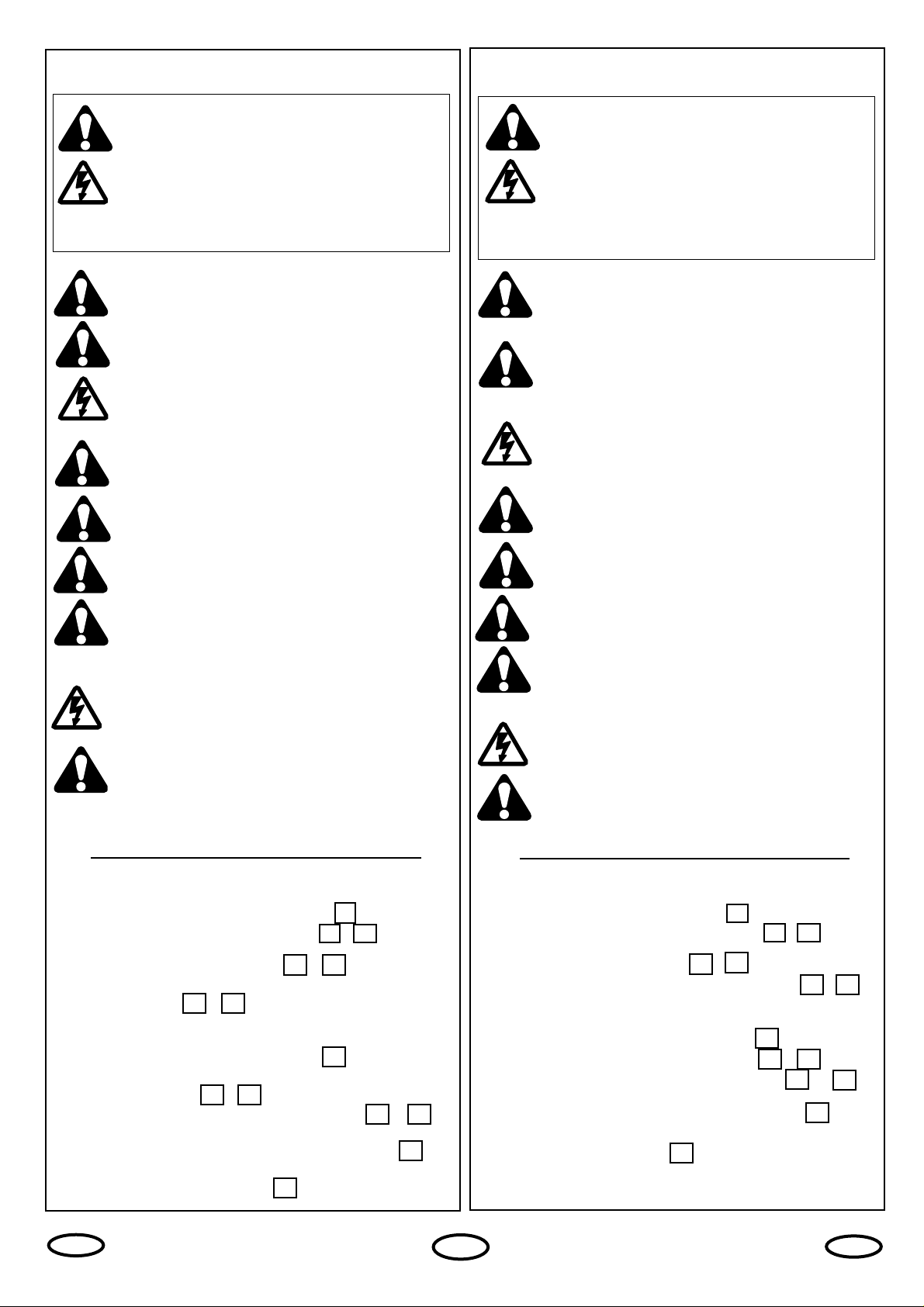
START BY READING THESE IMPORTANT SAFETY
RULES
These safety alert symbols mean
Caution
– a
personal safety or property damage instruction.
Read these instructions carefully.
This gate opener is designed and tested to offer
reasonable safe service provided it is installed
and operated in strict accordance with the
following safety rules.
Failure to comply with the following instructions may
result in serious personal injury or property damage.
1
Contents:
Safety Rules: Page 1
Contents of the carton: Page 2, Illustration
Product description: Page 2 Illustrations -
Technical data: Page 2
Installation: Pages 2-3, Illustrations -
Intallation of Wing Gate Actuator Unit:
Page 3, Illustrations -
Instruction Manual Logic Control Box: Page 4
Technical Features: Page 4
Electrical Installation: Page 4, Illustration
Summary of Motor Control Connections:
Pages 5-6, Illustrations -
Installation of Accessories: Page6- Illustrations -
Initial Setting of Motor Control System: Page 7
Initial Setting of Remote Control: Page 7, Illustration
Warranty: Page 8
Accessories: Page 12, Illustration
2
3
4
6
12
1
Handle tools and hardware carefully and do not
wear rings, watches or loose clothing
while
installing or servicing a gate opener.
Installation and wiring must be in compliance with
your local building and electrical codes.
Connect the
power cord only to properly earthed mains.
CAUTION: Activate opener only when the gate is
in full view, free of obstructions and opener is
properly adjusted. Do not allow children to play
near the gate.
Disconnect electric power to the gate opener
before making repairs.
Disengage all existing gate locks
to avoid damage
to gate opener.
Keep gate balanced
. Sticking or binding gates must
be repaired.
Do not attempt to repair the gates
yourself.
Call for service.
Keep additional accessories
out of the reach of
children. Do not allow children to operate push
button(s) or remote control(s).
Serious personal
injury from a closing gate may result from
misuse
of
the opener.
Ensure that
persons
who
install, maintain or
operate the gate opener follow these instructions.
Keep this
manual
where it can be readily
referenced
during maintenance.
BEGINNEN SIE MIT LESEN DIESER WICHTIGEN
SICHERHEITSREGELN
Beim Umgang mit Werkzeugen und Kleinteilen
Vorsicht walten lassen und weder Ringe, Uhren
noch lose Kleidungsstücke tragen, wenn Sie
Installations- oder Reparaturarbeiten an einem Tor
vornehmen.
Elektrische Leitungen sind entsprechend den lokalen
Bau- und Elektroinstallationsvorschriften zu verlegen.
Das
elektrische Kabel darf nur an ein ordnungsgemäß
geerdetes Netz angeschlossen werden.
VORSICHT! Betätigen Sie den Öffner nur, wenn Sie
das Tor voll im Blickfeld haben, sich dort keine
behindernden Gegenstände befinden und der
Öffner richtig eingestellt ist. Kinder sollten nicht in
Tornähe bei Betätigung des Öffners spielen.
Unterbrechen Sie den Storm zum Torantrieb bevor
Sie Reparaturen machen.
Enffernen Sie bitte alle am Tor angebrachten
Schlösser um Schaden am Tor zu vermeiden.
Es ist wichtig, das Tor immer gut gangbar zu
halten.
Tore die steckenbleiben oder verklemmen,
sind unverzüglich zu reparieren.
Versuchen Sie
nicht das Tor selbst zu reparieren.
Bestellen Sie
dafür einen Fachmann.
Entfernen Sie zusätzliches Zubehör aus der Nähe
von Kindern
. Erlauben Sie Kindern nicht
Drucktaster und Fernbedienungen zu bedienen.
Schwere Verletzungen können durch ein sich
schließendes Tor verursacht werden.
Stellen Sie sicher, daß
Personen, die den Antrieb
montieren, warten oder bedienen diesen
Anleitungen folgen.
Bewahren Sie die Anleitung an einem Ort auf, an
dem schnell auf sie zurückgegriffen werden kann
.
Solche Warnzeichen bedeuten “
Vorsicht!”
, eine
Aufforderung zur Beachtung, da ihre Mißachtung
Personen- bzw. Sachschäden verursachen kann.
Bitte lesen Sie diese Warnungen sorgfältig.
Dieser Toröffner ist so konstruiert und geprüft,
daß er bei Installation und Benutzung unter
genauer Befolgung der anschließenden
Sicherheitsregeln angemessene Sicherheit bietet.
Die Nichtbeachtung der folgenden Sicherheitsregeln kann
ernsthafte Personen- oder Sachschäden verursachen.
Inhalt:
Sicherheitsregeln: Seite 1
Inhalt des Kartons: Seite 2, Abbildung
Produktbeschreibung: Seite 2, Abbildungen -
Technische Daten: Seite 2
Montage: Seite 2-3, Abbildungen -
Einbau des Drehtorantriebes: Seite 3,Abbildungen -
Montageanleitung Elektronik: Seite 4
Technische Eigenschaften: Seite 4
Elektrische Installation: Seite 4, Abbildung
Anschlußübersicht: Seite 5-6, Abbildungen -
Installation von Zubehör: Seite 6, Abbildungen -
Grundeinstellung: Seite 7
Einstellung der Fernbedienung: Seite7, Abbildung
Garantie: Seite 8
Zubehör: Seite 12, Abbildung
2 3
4
6
7
12
1
13
7
14 18
19 31
32
33
13
14 18
19
31
32
33
D
GB
Page 4
2
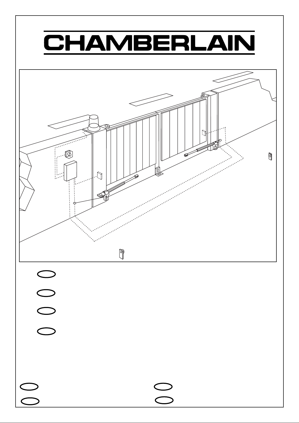
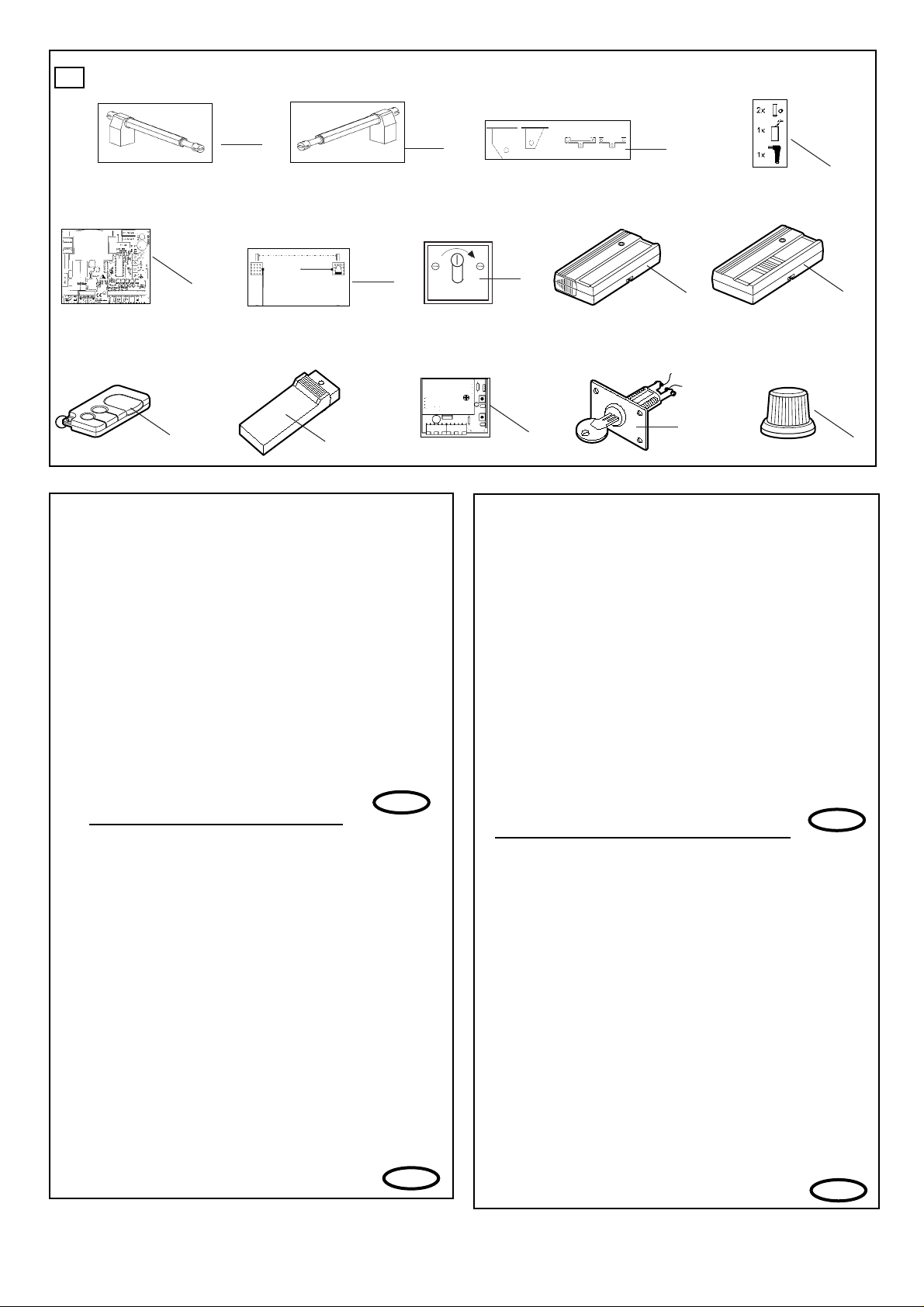
CONTENTS OF THE CARTON
(1) Wing gate actuator unit for left-hand installation and/or
(2) Wing gate actuator unit for right-hand installation
(3) Mounting brackets
(4) Installation accessories pack
Hinge pins with circlips (2)
Emergency opening handle (1)
Capacitor (1)
(5) Instruction manual
(6) Warning light kit
(7) IR Sensors
(8) Transmitter
(9) Control box
PRODUCT DESCRIPTION -
HC300R, HC300L, HC400R+L
Scope of application: Motorized opening and closing of
gates.
Illustration 3 shows a dimensional outline of the actuator arms.
The actuator units are suitable for use with single and double
gates. For HC300, the maximum gate width may not exceed
2.5 m and for HC400 it may not exceed 3.0 m. Maximum
weight 300 kg per gate.
For design reasons, all wing gate actuator units, operating
with linear movement, must follow the given installation
dimensions.
Some gate or post types may require recessing
of the post or use of the longer stroke actuator, in order to
achieve the installation dimensions.
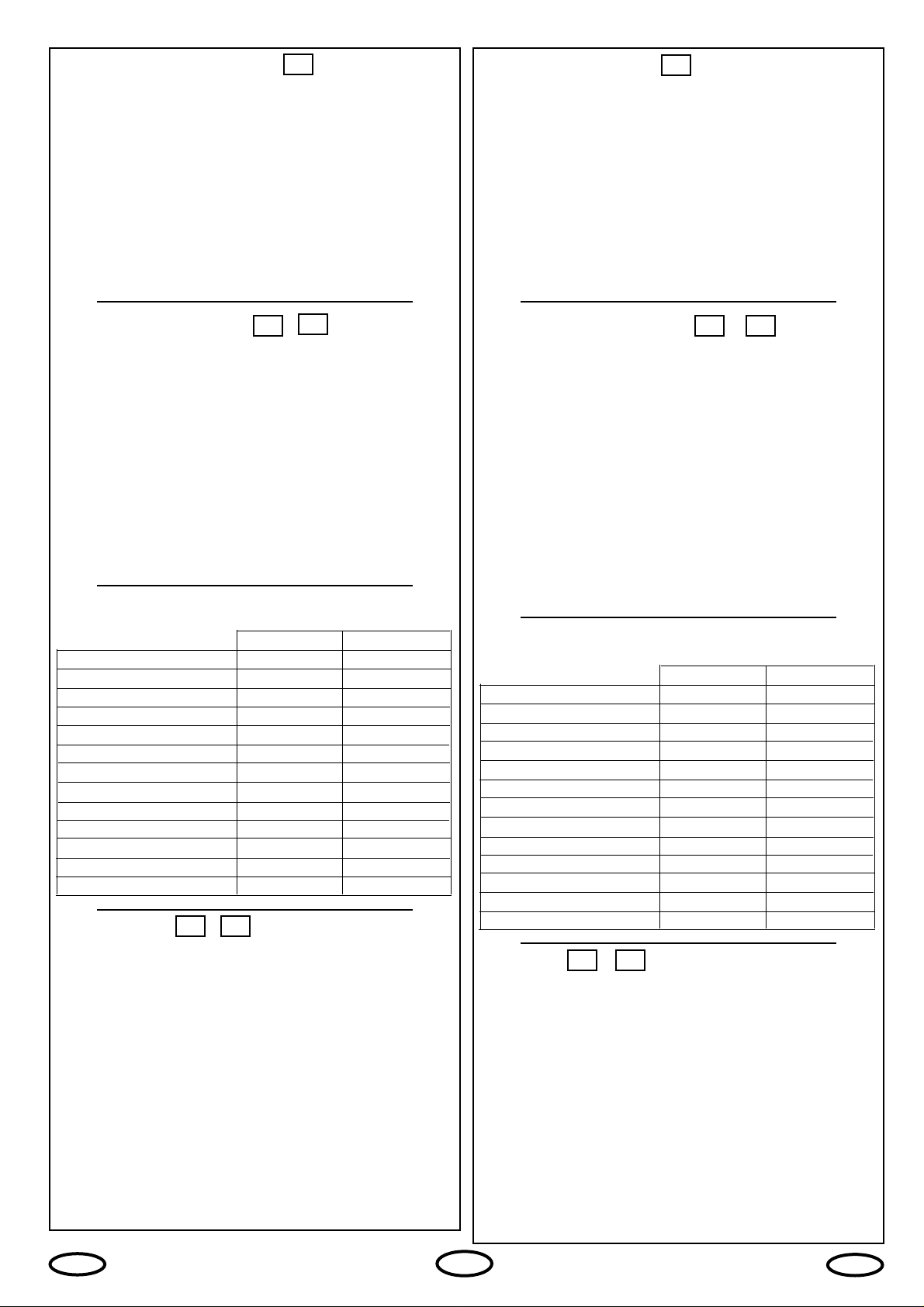
Technical data
HC300 HC400
Power supply 230V - 50Hz 230V - 50Hz
Capacitor 10 µF 10 µF
Current drawn 1.5 A 1.5 A
Power 350W 350W
Opening angle 110° max 110° max
Max. cycles/hours 20 20
Force 200kg 200kg
Max. actuator unit length 97cm 112cm
Motor thermal overload switch 140 °C 140 °C
Rated weight of motor 6.5kg 7kg
Dimensions see fig.3 see fig.3
Speed 1.5cm/s 1.5cm/s
IP Rating (motor) IP54 IP54
INSTALLATION -
Preparations
Before installation, please check contents of packaging.
Please refer to Illustration 1.
Ensure your gate equipment functions correctly.
Please keep in mind, that you will need parts not included in
the packaging (tubes, cable, screws, rawlplug and so on)
Installation preparation
As an example, Illustration 4 illustrates installation with a
stone or steel post construction. The installation dimensions
for the gate actuator unit are dependant on the fastening
points of gate to post.
llustration 5 shows the meaning of installation dimensions A
and B. The measurements chosen also
determine the opening
and closing times and the maximum opening angle of the gate.
Sample for A=14cm and B=14cm (approx. 900)
1
INHALT DES KARTONS
(1) Drehtorantrieb für Linkseinbau und/oder
(2) Drehtorantrieb für Rechtseinbau
(3) Scharnierteile zur Befestigung
(4) Montagezubehörbeutel
Befestigungsbolzen mit Sicherheitsringen (2)
Notentriegelung (1)
Kondensator (1)
(5) Montageanleitung
(6) Warnlampe
(7) Sicherheitslichtschranke
(8) Handsender
(9) Steuerung
PRODUKTBESCHREIBUNG -
HC300R, HC300L, HC400R+L
Bestimmungsgemäßer Gebrauch: Motorisiertes Öffnen und
Schließen von Toren.
Abbildung 3 zeigt die Abmessungen der Antriebe.
Die Antriebe sind für ein -und zweiflügelige Tore geeignet Die
Breite eines Torflügels darf beim HC300 nicht über 2,5 m,
beim HC400 nicht über 3,0 m betragen. Maximales Gewicht
300kg pro Flügel.
Bauartbedingt müssen bei allen Drehtorantrieben, die mit
linearer Bewegung arbeiten, bestimmte Einbaumaße
eingeghalten werden.
Je nach Beschaffenheit des Pfeilers
oder Torflügels können diese Maße nur durch Ausparungen
am Pfeiler oder durch Verwendung von Antrieben mit
größerem Hub erreicht werden.
Technische Daten
HC300 HC400
Netzanschluß 230V - 50Hz 230V - 50Hz
Kondensator 10 µF 10 µF
Stromaufnahme 1.5 A 1.5 A
Leistungsaufnahme 350W 350W
Öffnungswinkel 110° max 110° max
Max. Zyklen/Std. 20 20
Zugkraft 200kg 200kg
Max. Antriebslänge 97cm 112cm
Motorthermoschutz 140 °C 140 °C
Nettogewicht Motor 6.5kg 7kg
Abmessungen siehe Abb..3 siehe Abb..3
Geschwindigkeit 1.5cm/s 1.5cm/s
IP Werte (Motor) IP54 IP54
MONTAGE -
Vorbereitungen
Überprüfen Sie bitte vor der Montage den Inhalt der
Verpackung auf Vollständigkeit. Siehe Abbildung 1.
Stellen Sie die einwandfreie Arbeitsweise Ihrer Torvorrichtung
sicher.
Bedenken Sie, daß Sie noch Material benötigen, daß
sich verständlicherweise nicht in unserem Lieferumfang
befinden kann (Leerrohr, Kabel, Schrauben, Dübel etc.)
Montagevorbereitungen
Beispiele für eine Montage an Mauerwerk oder Stahlpfeilern
sind in Abb. 4 dargestellt. Die Montagemaße eines Torantriebes
sind von der Befestigung des Torflügels am Pfeiler abhängig.
Abb. 5 zeigt die Bedeutung der Einbaumaße A und B. Die
gewählten Maße bestimmen gleichzeitig die Öffnungs- und
Schließzeit und den maximalen Öffungswinkel eines Torflügels.
Beispiel für A=14cm und B=14cm (für ca. 900)
1
2
2
3
3
4
6
4 6
D
GB
Page 5

As a rule:
B greater than A slower, smoother closing, gate
opens faster.
A greater than B greater opening angle, however, when
closing, the gate makes a harder and
faster contact with the post stop.
For an opening angle of 90°, addition of the dimensions A
and B always gives the total actuator stroke. When a gate
opening angle greater than 90° is required, dimension B will
need to be reduced accordingly.
In order to obtain the optimum dimensions, it may be
necessary to shorten or lengthen the hinge plates supplied.
In the case of a new gate, dimensions Aand B may be
changed when the gate angle brackets are fastened to the
post accordingly. Before the installation dimensions are
finalised, ensure that the gate actuator unit does not touch
the post when moving.
Please refer to Illustration 6 - Table. (
If only one value is
stated: value for HC300/HC400 identical.)
To avoid undesirable jerking movement, the gate should be
stable and the angle brackets should have as little play as
possible.
The easier the gate movement, the finer the torque
adjustment
. Fragile wooden gates should be reinforced with
a metal frame.
INSTALLATION OF WING GATE
ACTUATOR UNIT -
(1) Fasten the hinge elements to the gate and post
in
accordance with the installation dimensions calculated
beforehand
. The
smaller element
is to be fitted to the gate
and the
larger
fitted to the post (Illustration 7).
NOTE:
The hinge elements must be vertically aligned to
one another
The force which the actuator unit applies against the post is
considerable. Asteel post is the most suitable from the
stability point of view. Quite acceptable installation
dimensions are usually obtained when the hinge plates
supplied are welded directly onto the post.
In the case of thick stone or concrete posts, the hinge
element must be welded onto a support plate and then
fastened in such a way that the dowels cannot become loose
during operation. For this purpose,
glued shear connectors
, in
which
a threaded rod is inserted into the wall without pressure
,
are more suitable than steel or plastic expansion dowels.
In the case of brick walls, a large steel plate, covering
several bricks, should be screwed onto the wall and the hinge
plate welded onto this base plate. An angle iron over the
corner of a post is also a suitable fastening support.
(2) Place a
water-tight junction box
next to the hinge plate on
the post. The Wing gate motor supply cable is led into this
box from below (Illustration 8).
(3) Using the hexagonal handle supplied,
release the actuator
unit by loosening the emergency release screw a half-turn in the
clockwise direction
. Then extend the actuator to its maximum
length. Re-tighten the actuator unit by turning the screw a halfturn in the anticlockwise direction (Illustrations 9 and 10).
With the gate closed, slide the
fully extended actuator
onto
the hinge element and fasten it using the hinge pins
supplied
in the accessories pack
. The hinge pins are blocked using
the circlips which are inserted into the bottom groove of the
hinge pins (Illustrations 11 and 12).
3
Grundsätzlich gilt:
B größer als A langsameres, sanftes Schließen, Flügel
wird beim Öffnen schneller
A größer als B großer Öffnungswinkel, Flügel fährt aber
beim Schließen schnell und hart an den
Pfeileranschlag an
Für einen Öffnungswinkel von 90° ergibt die Addition der
Maße Aund B immer den gesamten Kolbenhub. Soll der
Torflügel weiter als 90° aufgehen, muß das Maß B
entsprechend verkleinert werden.
Um optimale Maße zu erreichen, kann es nötig sein, die
mitgelieferte Scharnierplatte zu kürzen oder zu verlängern.
Bei neu anzufertigenden Toren kann, wenn die Torangeln an
den Pfeilern entsprechend montiert werden, Einfluß auf die
Maße Aund B genommen werden. Bevor die Anbaumaße
endgültig festgelegt werden, sollte immer geprüft werden, ob
der Antrieb beim Schwenken nicht am Pfeiler anecken könnte.
Siehe Abb. 6 - Beispeiltabelle. (
Bei Angabe nur eines
Meßwertes: Meßwert für HC300/HC400 identisch.)
Um störende Pendelbewegungen zu vermeiden sollte der
Flügel stabil und die Torangeln möglichst spielfrei sein. Je
leichtgängiger der Flügel, desto feinfühliger ist die Kraft
einzustellen. Labile Holztore sollten mit einem Metallrahmen
verstärkt werden.
MONTAGE DES DREHTORANTRIEBES -
(1) Bringen Sie gemäß den zuvor ermittelten Einbaumaßen
die Scharnierteile an Torflügel und Pfeiler an. Das kleinere
Teil ist für den Torflügel vorgesehen, das größere für den
Pfeiler (Abb. 7).
ANNMERKUNG:
Die Scharnierteile müssen zueinander
waagerecht ausgerichtet sein.
Die Kräfte, mit denen sich der Antrieb gegen den Pfeiler
abstützt, sind sehr groß. Ein Stahlpfeiler bereitet von der
Stabilität her die wenigsten Probleme. Meistens ergeben sich
schon akzeptable Einbaumaße, wenn die mitgelieferte
Scharnierplatte direkt an den Pfeiler geschweißt wird.
Bei dicken Stein- oder Betonpfosten muß das Scharnierteil
auf eine Trägerplatte geschweißt und so befestigt werden,
daß sich die Dübel im Betrieb nicht lockern können.
Besser
als Stahl- oder Kunststoff-Spreizdübel eignen sich hierzu
Klebe-Verbundanker, bei denen ein Gewindestift Spannungsfrei
im Mauerwerk eingeklebt wird.
Bei gemauerten Pfeilern sollte eine größere Stahlplatte,
mehrere Steine überdeckend, angeschraubt werden, auf die
dann die Scharnierplatte aufgeschweißt werden kann. Gut
zur Befestigung eignet sich auch eine um die Pfeilerkante
befestigte Winkelplatte.
(2) Setzen Sie neben die Scharnierplatte am Pfeiler eine
wasserdichte Verteilerdose
. Hier wird das Anschlußkabel des
Drehtorantriebes von unten eingeführt (Abb. 8).
(3)
Entriegeln Sie den Antrieb, indem Sie die
Notentriegelungsschraube mit dem mitgelieferten
Sechskantschlüssel um eine halbe Drehung im Uhrzeigersinn
drehen
. Ziehen Sie dann den Kolben auf fast maximale Länge
heraus. Verriegeln Sie anschließend den Antrieb wieder durch
eine halbe Drehung im Gegenuhrzeigersinn (Abb. 9 und 10).
Schieben Sie anschließend bei
geschlossenem Torflügel
den auf
maximal zulässige Länge ausgezogenen Antrieb auf die
Scharnierteile auf und befestigen Sie ihn mit Hilfe der im
Zubehörbeutel enthaltenen Bolzen.
Die Bolzen werden durch
die auf die untere Bolzennut aufzuschiebenden Sicherheitsringe
gesichert (Abb. 11 und 12).
7
12
7
12
D
GB
Page 6

A
8 10 12 14 16 18 20 22 24
8 100
0
110
0
120
0
125
0
1100/13101000/1150930/1200880/1090840/102
0
10 99
0
108
0
115
0
121
0
1010/1250930/1280890/1130830/104
0
B 12 95
0
105
0
110
0
1050/1180930/1220860/1180820/105
0
14 95
0
100
0
108
0
950/1150870/118
0
16 94
0
100
0
106
0
930/110
0
18 97
0
97
0
20 91
0
HC300: 62 cm
HC400: 72 cm
HC300: 92 cm / HC400: 1
10 cm
5
9
1
2
3
4
5
6
7
8
9
1
2
3
4
6
CHAMBERLAIN
INSTRUCTION MANUAL
2.5m Swing Gate Opener - HC300
3.0m Swing Gate Opener - Hc400
Chamberlain
Alfred-Nobel-Str. 4
D-66793 Saarwelligen
(49) 6838/907-200
Page 7

7
8
10
11
12
10
9
13
1 2 3
4 5
6 7 8
9 10 11
++
12 13
17 18
22 23
24 25
14 15 16
19 20 21
26 27
14
15
16
17
18
• • •
L1 PE N
230V 230V
Earth/Erdung/
19
21
22
20
--
L6
JP1
L4 L3 L2 L1
L5
2
7
8
6
schwarz, noir
braun, marron
gelb/grün, jaune/vert
Capacitor/Kondensator/
Condensateur
blau, bleu
1
222
3
4
black
blue
brown
yellow/green
JP2
Capacitor/Kondensator/
Condensateur
black
1
blue
2
brown
yellow/green
3
4
2
schwarz, noir
blau, bleu
braun, marron
gelb/grün, jaune/vert
7
8
6
Page 8

Left
Right
Left
Right
23
24
14 15 16
17 18
19 20 21
22 23
24 25 26 27
12 13
25
14 15 16
17 18
1920 21
22 23
26
14 15 16
17 18
19 20 21
22 23
24 25 26 27
12 13
27
17 18
19 20 21
22 23
28
17 18
19 20 21
22 23
29
22 23
24 25 26 27
30
22 23
24 25 26 27
31
32
11
Capacitor/Kondensator/
2
1
marron
brown/braun/
++
--
Condensateur
3
2
noir
yellow/green,
blue/blau/bleu
black/schwarz/
6
4
gelb/grün,
jaune/vert
Condensateur
1
noir
black/schwarz/
2
blue/blau/bleu
brown/braun/
3
marron
4
yellow/green,
gelb/grün,
jaune/vert
Capacitor/Kondensator/
10
11
9
7
8
Capacitor/Kondensator/
2
Condensateur
2
1
marron
brown/braun/
blue/blau/bleu
black/schwarz/
6
3
4
noir
gelb/grün,
jaune/vert
yellow/green,
Capacitor/Kondensator/
Condensateur
3
2
1
noir
marron
yellow/green,
brown/braun/
blue/blau/bleu
black/schwarz/
4
gelb/grün,
jaune/vert
10
11
9
7
8
--
++
➔
SWITCH
➔
SWITCH
➔
SWITCH
2
1
10-15m
75
Ω
Page 9

TECHNICAL FEATURES
Power supply 230V-50Hz
Absorbed power 10W
Max. motor load 700W
Max. load on accessories 0.9A
Auxilliary output 24V AC
Protection fuses 4
Operating logic Step by step/Automatic
Housing Dimensions 90x195x250mm
Housing drgree ofProtection IP54
ELECTRICAL INSTALLATION
The electronic control unit supplied is required for operation
of the wing gate actuator. This control unit comprises an
electronic microprocessor-control system employing the latest
technology. It may be used for the connection of 1 or 2
motors and offers all connection possibilities and functions
necessary for
safe and reliable operation.
The electrical connections for single- or double gates are
given in Illustration 13.
The control box containing the motor control module is to be
fitted with cable entry at bottom. It should not be continuously
exposed to direct sunlight. For weather protection, we
recommend the fitting of a small protection roof.
Thanks to the electronic control unit, fine adjustment of the
push-pull torque is possible. When correctly adjusted, gate
movement can be easily blocked by hand.
For the OPEN and CLOSED positions, the gate requires a
stable end stop as the swing gate actuator unit is not
fitted with limit switches and the electronic controls are
switched off by time.
4
TECHNISCHE EIGENSCHAFTEN
Netzanschluß 230V-50HzHz
Stromverbrauch 10W
Max.Motorbelastung 700W
Max. Belastung Zubehör 0.9A
Max. Belastung E-Schloß 24V AC
Sicherungen 4
Betriebslogik Schritt für Schritt/Automatik
Abmessungen 90x195x250mm
Schutz IP54
ELEKTRISCHE INSTALLATION
Zum Betrieb des Drehtorantriebs ist die mitgelieferte
elektronische Steuerung erforderlich. Bei dieser Motorsteuerung
handelt es sich um eine mikroprozessorgesteuerte Elektronik
mit modernster Technik. Sie ist für den Anschluß von bis zu 2
Motoren geeignet und hat alle für den sicheren Betrieb
notwendigen Anschlußmöglichkeiten und Funktionen.
Der elektrische Anschluß ist für Einflügel- und Zweiflügel-Tore in
einer Übersicht in Abb. 13 dargestellt.
Die Steuerbox mit der Motorsteuerung ist mit den
Kabeldurchführungen nach unten zu montieren. Sie darf
direkter Sonneneinstrahlung nicht dauernd ausgesetzt sein. Es
empfiehlt sich, als Schutz vor Regen ein kleines Schutzdach zu
montieren.
Das Tor läßt sich bei richtiger Einstellung von Hand
festhalten.
Während des Laufes kann das Tor jederzeit über Funk, Taster
oder Schlüsselschalter gestoppt werden.
Der Torflügel benötigt für "AUF-" und "ZU"-Stellung
einen stabilen Anschlag, da die Drehtorantriebe keine
Endschalter besitzen und die Abschaltung der Elektronik
über die Zeit erfolgt.
13
13
D
GB
Page 10

SUMMARY OF
MOTOR CONTROL CONNECTIONS -
Description of connections
Main supply connections:
Terminal 1 L1 - 230 V (black)
Terminal 2 PE (green/yellow)
Terminal 3 N (blue)
Warning light connections:
Terminal 4 N
Terminal 5 L1 (230V)
Motor connections:
First Motor (M1):
Terminal 6 M1 actuator unit direction OPEN
(+ capacitor)
Terminal 7 N Blue
Terminal 8 M1 actuator unit direction CLOSE
(+ capacitor)
Second Motor (M2):
Terminal 9 M2 actuator unit direction OPEN
(+ capacitor)
Terminal 10 N Blue
Terminal 11 M2 actuator unit direction CLOSE
(+ capacitor)
Gate status LED
Terminal 12 LED (2 Volt)
Terminal 13 LED (2 Volt)
Off - gate opening
On - gate closing
Slow flashing - gate opening
Fast flashing - gate closing
Infrared light detector
Terminal 14 Photocell (NC)
Terminal 15 COM
Terminal 16 Photocell (NC)
(If the IR barrier is not used, bridge terminals
14,15 and 16 must be bridged!)
Description of connections
Emergency-Stop-function
Terminal 17 COM
Terminal 18 Stop (NC) or bridge between 17 and 18
Control circuit connections:
Terminal 19 Outside button (NO) Motor 1 (Pedestrian function)
Terminal 20 COM
Terminal 21 Outside button (NO) Motor 1 + 2
Auxiliary equipment connections:
Terminal 22 Supply voltage 24 V AC (500 mA max.)
Terminal 23 Supply voltage 24 V AC
Electric lock connections:
Terminal 24 Supply voltage 12 V AC
Terminal 25 Supply voltage 12 V AC
Antenna connections:
Terminal 26 Antenna (wire)
Terminal 27 Shield
DESCRIPTION OF JUMPERS
JP1: MOTOR SELECTION JUMPER
OPEN: (No Jumper): Use only for single wing gates
(Motor 1 operation only).
CLOSED: (With Jumper): Use for double wing gates
(Motor 1 and 2 operation).
JP2: TWO CHANNEL RECEIVER JUMPER SELECTION
OPEN: (No Jumper): Receiver channel 2
is activated.
CLOSED: (With Jumper): Receiver channel 2
is not activated.
ANSCHLUßÜBERSICHT -
Beschreibung der Klemmenbelegung
Anschluß der Zuleitung:
Klemme 1 L1 - 230 V (schwarz)
Klemme 2 PE (grün/gelb)
Klemme 3 N (blau)
Anschluß der Warnlampe:
Klemme 4 N
Klemme 5 L1 (230V)
Anschlüsse der Motoren:
Erster Motor (M1):
Klemme 6 M1 Fahrtrichtung AUF
(+ Kondensator)
Klemme 7 N Blau
Klemme 8 M1 Fahrtrichtung ZU
(+ Kondensator)
Zweiter Motor (M2):
Klemme 9 M2 Fahrtrichtung AUF
(+ Kondensator)
Klemme 10 N Blau
Klemme 11 M2 Fahrtrichtung ZU
(+ Kondensator)
Anzeige LED
Klemme 12 LED (2 Volt)
Klemme 13 LED (2 Volt)
AUS - Tor geschlossen
AN - Tor offen
Blinkt langsam - Tor öffnet
Blinkt schnell - Tor schließt
Infrarot-Lichtschranke
Klemme 14 Photozelle (NC)
Klemme 15 COM
Klemme 16 Photozelle (NC)
(Ohne Lichtschranke - Brücke zwischen 14, 15
und16!)
Beschreibung der Klemmenbelegung
NOTSTOP-FUNCTION
Klemme 17 COM
Klemme 18 Stop (NC) ohne Notstopschalter Brücke
zwischen 17 und 18
Anschluß der Steuerleitungen:
Klemme 19 Taster extern (NO) Motor 1 (Fußgänger-Funktion)
Klemme 20 COM
Klemme 21 Taster extern (NO) Motor 1 + 2
Anschluß für Zusatzgeräte & Lichtschranke:
Klemme 22 Versorgungsspannung 24 V AC (500 mAmax.)
Klemme 23 Versorgungsspannung 24 V AC
Anschluß für Elektroschloß:
Klemme 24 Versorgungsspannung 12 V AC
Klemme 25 Versorgungsspannung 12 V AC
Anschluß für Antenne:
Klemme 26 Antenne (Leiter)
Klemme 27 Abschirmung
BESCHREIBUNG DER JUMPER
JP1: MOTOR
OPEN: (ohne Jumper): Nur für einflügelige Tore
(nur Motor 1 Bedienung).
CLOSED: (mit Jumper): Nur für zweiflügelige Tore
(Motor 1 und 2 Bedienung).
JP2: FUNK (ERMÖGLICHT ÖFFNEN EINES FLÜGELS)
OPEN: (ohne Jumper): Empfänger Kanal 2
wird aktiviert.
CLOSED: (mit Jumper): Empfänger Kanal 2
wird nicht aktiviert.
5
14
18
14 18
15
15
D
GB
Page 11

6
DESCRIPTION OF LEDS:
L1 Impulse on M1+M2 on: impulse
off: no impulse
L2 Impulse on M1 on: impulse
(Pedestrian Function) off: no impulse
L3 Stop function on: not activated
off: activated
L4 Infrared barrier on: IR barrier not
interrupted
off: IR barrier interrupted
L5 Infrared barrier on: IR barrier not
interrupted
off: IR barrier interrupted
L6 Motor Diagnostic slow flash: O.K.
fast flash: motor or motor
wiring defect
DESCRIPTION OF DIP SWITCHES
1 2 3 4
Operation Automatic closing on
Logic Step by step off
Parkfunction Impulses are detected
during opening on
No impulses are tetected
during opening off
Electrical Operation with E-Lock on
Lock Operation without E-Lock off
IR barrier Stops and starts after release on
Stops and restarts directly off
DESCRIPTION OF POTENTIOMETERS
A Torque adjustment of both motors
B Pause:waits open form 8-200 sec. (only operation
logic: “automatic”)
C Running time : it is recommendable to set this time
longer then the gate needs to open or close
D Delay of second wing: 0 - 25 sec.
INSTALLATION OF ACCESSORIES -
POWER CONNECTION
WARNING LIGHT
ACTUATOR
Motor drive unit wiring diagram
♦ Left hand installation
♦ Right hand installation
Dual installation
♦ Left gate opens first
♦ Right gate opens first
GATE STATUS INDICATOR
INFRARED BARRIER
♦ IR barrier for opening and closing - (If using 1 IR barrier)
EMERGENCY STOP SWITCH (OPTIONAL)
If not used, please bridge
WALLCONTROL (OPTIONAL)
Motor 1
Motor 1 + 2
ELECTRICAL LOCK (OPTIONAL)
ANTENNA
Please use an 22cm insulated cable as Antenna. (terminal 26)
Please use a coaxial cable (75 Ohm) to transport the signals.
BESCHREIBUNG DER LEDS:
L1 Impuls an M1+M2 an: Impuls
aus: kein Impuls
L2 Impuls an M1 an: Impuls
(Fußgänger-Funktion) aus: kein Impuls
L3 Notstop an: sperrt nicht
aus: Antrieb gesperrt
L4 Infrarot-Lichtschranke an: sperrt nicht
aus: Antrieb sperrt
L5 Infrarot-Lichtschranke an: sperrt nicht
aus: Antrieb sperrt
L6 Motor Diagnose blinkt langsam: O.K.
blinkt schnell: Anschlüsse
prüfen
BESCHREIBUNG DER DIPSCHALTER
1 2 3 4
Betriebs- Automatisch schließend an
logik Schrittweise aus
Betriebs- Reagiert auf Impulse
logik während des Öffnens an
Reagiert nicht auf Impulse
während des Öffnens aus
Elektro- E-Schloß in Verwendung an
schloß Ohne E-Schloß aus
Photozelle Stoppt an
Stoppt und öffnet aus
BESCHREIBUNG DER POTENTIOMETER
A Krafteinstellung beider Motoren
B Pause: wartet offen 8-200 Sek. (nur Betriebslogik:
Automatik
C Laufzeit: Um korrekte Funktion zu gewährleisten, ist es
notwendig, daß der Antrieb noch einige Sekunden nach
Ankunft am Endanschlag mit Strom versorgt wird.
D Verzögerung des zweiten Flügels: Einstellbar von 0-25
Sekunden. Notwendig bei sich überlappenden Toren.
EINBAU VON ZUBEHÖR -
STROMANSCHLUß
WARNLAMPE
ANTRIEB
Diagramm
♦ Linkseinbau
♦ Rechtseinbau
Dualer Einbau
♦ Linkes Tor öffnet zuerst
♦ Rechtes Tor öffnet zuerst
TORANZEIGE
SICHERHEITSLICHTSCHRANKE
♦ Lichtschranke zum Öffnen und Schließen - (bei Benutzung
einer Lichtschranke)
NOTSTOPSCHALTER (OPTION)
Bei Nichtverwendung brücken
SCHLÜSSELSCHALTER (OPTION)
Motor 1
Motor 1 + 2
ELEKTRO-SCHLOß (OPTION)
ANTENNE
Als Antenne wird ein 22cm langes Kabel verwendet (Klemme 26)
Zum Transport des Funksignals wegen evt. Abschirmungen,
verwenden Sie bitte ein Koaxialkabel (75 Ohm).
16
16
17
17
18
18
19
31
19
31
19
19
23
22
21
20
26
24
25
27
30
28
31
29
20
21
22
23
24
25
26
27
29
28
30
31
D
GB
Page 12

7
INITIAL SETTING OF MOTOR CONTROL SYSTEM
(1) Connect the installation in accordance with wiring diagram
supplied.
(2) Place both gates in half-open position and block the motors.
(3) Adjust the motor controls to the following basic settings:
A - Adjust torque to approx. 25 % (to be increased later)
B - Switch off automatic closing (dip switch 2 OFF)
C - Travel time approx. 50%.
D - Switch off gate delay time (left end positon)
(4) Switch on power supply.
(5) Start the motor control by brigding terminal 20 and 21;
both gates should then move in the "OPEN" direction.
Should one or the other gate move in the "CLOSED"
direction, then the connection wires to the corresponding
motor must be inverted (black, brown).
Ensure the main power supply is off before inverting
wires!
(6) Repeat steps 5 and 6 until the required function is
obtained.
(7) In the case of overlapping gates, use potentiometer D to
set the optimum gate delay time. For gates which do not
overlap or for operation with a single gate, this
adjustment is not necessary.
(8) The travel time is adjusted with potentiometer C. It is
recommendable to set this time 2 or 3 seconds longer
than the gate actually needs to open or close.
(9) Adjust the motor torque in sucha way that it is sufficient
to stop the door by hand. Protection against damages
is only possible through installation of an IR barrier.
When automatic closing is required, set Dip switch 1 to ON
and use Potentiometer D to contol the waiting time.
INITIAL SETTING OF REMOTE CONTROL
The PTT-approved, charge-free radio remote control unit
functions with a
computer pre-programmed private
security code (approximately 3.5 billion code
possibilities)
. In this way, your swing gate control unit can
only be activated by handset with the correct code. The
operating range depends on local conditions.
The receiver module of the motor control unit has a built-in
self-learn function. It can be set in accordance with the preprogrammed code of the handset by pressing the learn
button (Illustration 32).
The control unit comprises 2 learn channels. In this way, the
handset may be used to open or close one gate only or both
gates simultaneously. When, for example, channel 1 (2.1)
receives the remote control code of the first control button of
the handset, then only one gate is opened. When the second
channel (2.2) is set in accordance with the remote control code
of the second control button, then both gates are operated
when this button is pressed.
In order to configure the control PCB pre-programmed code in
accordance with the handset, the learn and transmit buttons
for the required channel must be pressed and held until the
associated LED lights up briefly. When a multi-control handset
is used, this procedure must be repeated for each control
button and associated learn channel.
Repeat this procedure for every transmitter.
GRUNDEINSTELLUNG
(1) Anlage gemäß Anleitung anschließen.
(2) Beide Torflügel in halboffene Position bringen und
verriegeln.
(3) Motorsteuerung in folgende Grundeinstellung bringen:
A - Krafteinstellung auf ca. 25% (evtl. später erhöhen)
B - Dippschalter 2 Richtung OFF
C - Laufzeit ca. 50%
D - Potentiometer D auf Linksanschlag
(4) Stromversorgung anschließen.
(5) Betätigen Sie den an 20 und 21 angeschlossenen
Schalter oder brücken Sie kurz die Kontakte. Sollte einer
oder beide Motorflügel sich nicht in Richtung AUF
bewegen, tauschen Sie die Steuerkabel des jeweiligen
Motors (schwarz, braun).
Achtung: Zuerst immer die Netzspannung abschalten.
(6) Wiederholen Sie Schritte 5 und 6 bis sich die korrekte
Funktion einstellt.
(7) Sollten Sie überlappende Tore haben, stellen Sie mit
Potentiometer D die Verzögerung ein.
(8) Die Laufzeit einige Sekunden länger einstellen als die
tatsächlich benötigte Zeit.
(9) Stellen Sie die Kraftstärke so ein, daß Sie das Tor mit
der Hand stoppen können. Sicherheit gegen Schäden
erlangen Sie nur durch den Einsatz einer
Lichtschranke.
Sollten Sie die Funktion “Automatisch schließen” wünschen,
stellen Sie Dippschalter 1 auf ON und regulieren Sie mit
Potentiometer D die Wartezeit.
EINLERNEN DER FERNBEDIENUNG
Die postzugelassene, gebührenfreie Funkfernsteuerung
arbeitet mit einem
per Computer vorprogrammierten
privaten Sicherheitscode (ca. 3,5 Milliarden
Codiermöglichkeiten).
Damit kann Ihr Drehtorantrieb nur
mit einem entsprechend eingelernten Handsender betrieben
werden.(max. 4 mit 3,5 Mrd. Codierung). Die Reichweite ist
von örtlichen Begebenheiten abhängig.
Das Empfängerteil der Motorsteuerung hat eine integrierte
Selbstlernfunktion. Sie kann auf den vorprogrammierten
Code des Handsenders durch Drücken der Lerntaste
eingestellt werden (Abb. 32).
Die Steuerung besitzt zwei Lernkanäle. Sie kann damit durch
entsprechendes Betätigen des Handsenders ein Tor oder
beide Tore gleichzeitig öffnen oder schließen. Erhält
beispielsweise Kanal 1 (2.1) den Fernbedienungscode des
Handsenders, wird nur ein Flügel geöffnet. Lernen Sie den
Kanal 2 (2.2) der Fernbedienung an, können Sie mit dieser
Taste beide Flügel betätigen.
Um den Code einzuspeichern, drücken Sie die von Ihnen
gewählte Taste des Handsenders und halten diese fest.
Drücken Sie mit der anderen Hand kurz die Lerntaste der
Elektronik.
Wiederholen Sie den Vorgang für alle Handsender.
LÖSCHEN PROGRAMMIERTER
FERNBEDIENUNGSCODE:
Drücken Sie die jeweilige Lerntaste (2.1 oder 2.2 -
ca. 10
Sekunden
) auf der Empfängerplatine bis die Lern-LED
erlischt. Die zu dieser Lerntaste gehörenden “erlernten”
Codierungen sind dann gelöscht.
32
32
D
GB
Page 13

8
DELETION OF PROGRAMMED REMOTE-CONTROL
CODES:
Press the corresponding learn button (2.1 or 2.2 -
approx.
10 seconds)
on the receiver PCB until the learn LED goes
off. The code memorised with this learn button has now been
deleted.
REPROGRAMMING:
When reprogramming, the above-mentioned coding steps must
be repeated for all remote-control handsets in operation and
their control buttons.
The operating range of the remote-control unit depends on local
conditions. Press and hold the button on the handset (approx. 2
seconds) until the gate begins to move.
In the PTT-approved frequency range for the radio control of
gates, there are also medical, industrial, scientific, military and
household radio systems in operation, some of which have a
very high transmission range. The close proximity of such a
radio installation could lead to a reduction in operating range or
temporary interference in your radio remote-control system.
NEUPROGRAMMIEREN:
Zum Neuprogrammieren sind die genannten Schritte für die
Codierung für alle in Betrieb befindlichen Fernbedienungen
bzw. ihrer Bedienungstasten zu wiederholen.
Die Reichweite der Funkfernsteuerung ist von den örtlichen
Gegebenheiten abhängig. Halten Sie die Taste am
Handsender solange gedrückt (ca. 2 Sekunden), bis eine
Bewegung des Tores erkennbar ist.
In den von der Deutschen Bundespost genehmigten
Frequenzbereichen für Torantriebe gibt es auch Funkanlagen
für medizinische, industrielle, wissenschaftliche, militärische
und häusliche Zwecke mit zum Teil sehr hohen
Sendeleistungen. Befinden Sie sich in der Nähe solcher
Funkanlagen, kann das zu einer geringeren Reichweite oder
zu vorübergehenden Störungen Ihrer Funkfernsteuerung
führen.
Ihre Funkfernsteuerung ist digitalcodiert, d.h. eine
unbeabsichtigte Betätigung des Torantriebes kann nahezu
ausgeschlossen werden.
WARRANTY
CHAMBERLAIN warrants to the first retail purchaser of this
product that the product shall be free from any defect in
materials and/or workmanship for a period of 24 full months
(2 years) from the date of purchase for Model HC300/400
and the Electronic Control Upon receipt of the product, the
first retail purchaser is under obligation to check the product
for any visible defects.
Conditions: The warranty is strictly limited to the reparation
or replacement of the parts of this product which are found to
be defective and does not cover the costs or risks of
transportation of the defective parts or product.
This warranty does not cover non-defect damage caused by
unreasonable use (including use not in complete accordance
with CHAMBERLAIN's instructions for installation, operation
and care; failure to provide necessary maintenance and
adjustment, or any adaptations of or alterations to the
products), labor charges for dismantling or reinstalling of a
repaired or replaced unit or replacement batteries.
A product under warranty which is determined to be defective
in materials and/or workmanship will be repaired or replaced
(at CHAMBERLAIN's option) at no cost to the owner for the
repair and/or replacement parts and/or product. Defective
parts will be repaired or replaced with new or factory rebuilt
parts at CHAMBERLAIN's option.
This warranty does not affect the purchaser's statutory rights
under applicable national legislation in force nor the
purchaser's rights against the retailer arising from their
sales/purchase contract. In the absence of applicable
national or EC legislation, this warranty will be the
purchaser's sole and exclusive remedy and neither
CHAMBERLAIN nor its affiliates or distributors shall be liable
for any incidental or consequential damages for any express
or implied warranty relating to this product.
No representative or person is authorized to assume for
CHAMBERLAIN any other liability in connection with the sale
of this product.
GARANTIE
CHAMBERLAIN garantiert dem ersten Käufer, der das Produkt
im Einzelhandel erwirbt (erster "Einzelhandelskäufer") daß es,
ab dem Datum des Erwerbs volle 24 Monate (2 Jahre) lang
von jeglichen Materialschäden bzw. Herstellungsfehlern frei ist.
Diese Garantie gilt für die Modelle HC300/HC400 und die
Elektronische Steuerung. Bei Empfang des Produkts obliegt
es dem ersten Einzelhandelskäufer, dieses auf sichtbare
Schäden zu prüfen.
Bedingungen: Die vorliegende Garantie ist das einzige
Rechtsmittel, das dem Käufer gesetzmäßig wegen Schäden
zusteht, die mit einem defekten Teil bzw. Produkt in
Verbindung stehen bzw. sich aus einem solchen ergeben. Die
vorliegende Garantie beschränkt sich ausschließlich auf
Reparatur bzw. Ersatz der Teile dieses Produkts, die als
schadhaft befunden werden.
Die vorliegende Garantie gilt nicht für Schäden, die nicht auf
Defekte sondern auf den unrichtigen Gebrauch zurückzuführen
sind (d. h. einschließlich jedweder Benutzung, die nicht genau
den Anleitungen bzw. Anweisungen der Firma CHAMBERLAIN
hinsichtlich Installation, Betrieb und Pflege entspricht, sowie des
Versäumnisses, erforderliche Instandhaltungs- und
Justierungsarbeiten rechtzeitig durchzuführen, bzw. der
Durchführung von Adaptierungen oder Veränderungen an diesem
Produkt). Sie deckt auch nicht die Arbeitskosten für den Ausbau
bzw. den Wiedereinbau eines reparierten oder ersetzten Geräts
oder dessen Ersatzbatterien. Ein Produkt im Rahmen der
Garantie, hinsichtlich dessen entschieden wird, daß es
Materialschäden bzw. Herstellungsfehler aufweist, wird dem
Eigentümer ohne Kosten für Reparatur bzw. Ersatzteile nach
Gutdünken der Firma CHAMBERLAIN repariert oder ersetzt.
Sollte das Produkt während der Garantiezeit defekt erscheinen,
so wenden Sie sich bitte an die Firma, von der Sie es
ursprünglich gekauft haben.
Die Garantie beeinträchtigt nicht die dem Käufer im Rahmen
gültiger zutreffender nationaler Gesetze oder Statuten
zustehenden Rechte oder Rechte gegenüber dem Einzelhändler,
die sich für den Käufer aus dem Verkauf/Kaufvertrag ergeben. Bei
Nichtbestehen von zutreffenden nationalen bzw. EG-Gesetzen ist
diese Garantie das einzige und exklusive Rechtsmittel, das dem
Käufer zur Verfügung steht, und weder CHAMBERLAIN noch die
Filialen oder Händler der Firma sind für irgendwelche Nebenoder Folgeschäden durch jedwede ausdrückliche oder
stillschweigende Garantie bezüglich dieses Produkts haftbar.
Weder Vertreter noch sonstige Personen sind berechtigt, im
Namen von CHAMBERLAIN irgendeine sonstige Verantwortung
in Verbindung mit dem Verkauf dieses Produktes zu übernehmen.
D
GB
 Loading...