

Page 1
Chamberlain GmbH
Alfred-Nobel-Str. 4
D66793 Saarwellingen
www.chamberlain.de
13.5m
2
110kg
13.5m
2
110kg
Instructions – Garage Door Operator Model GPD60, GPD65
Instrucciones – Abridor de la puerta de garaje, Modelo GPD60, GPD65
Istruzioni – Apriporta per garage Modello GPD60, GPD65
Instruções – Operador automático de porta, Modelo GPD60, GPD65
en
es
it
pt
GPD60 GPD65
13.5
7,4m
110kg
60kg
Max. m2/kg
2
13.5
10m
110kg
80kg
Max. m2/kg
2
es
it
en
pt
(+34) 902 88 33 79
(+39) 02 303 52006
(+44) 0800 317847
707 785 454
Page 2
en-1
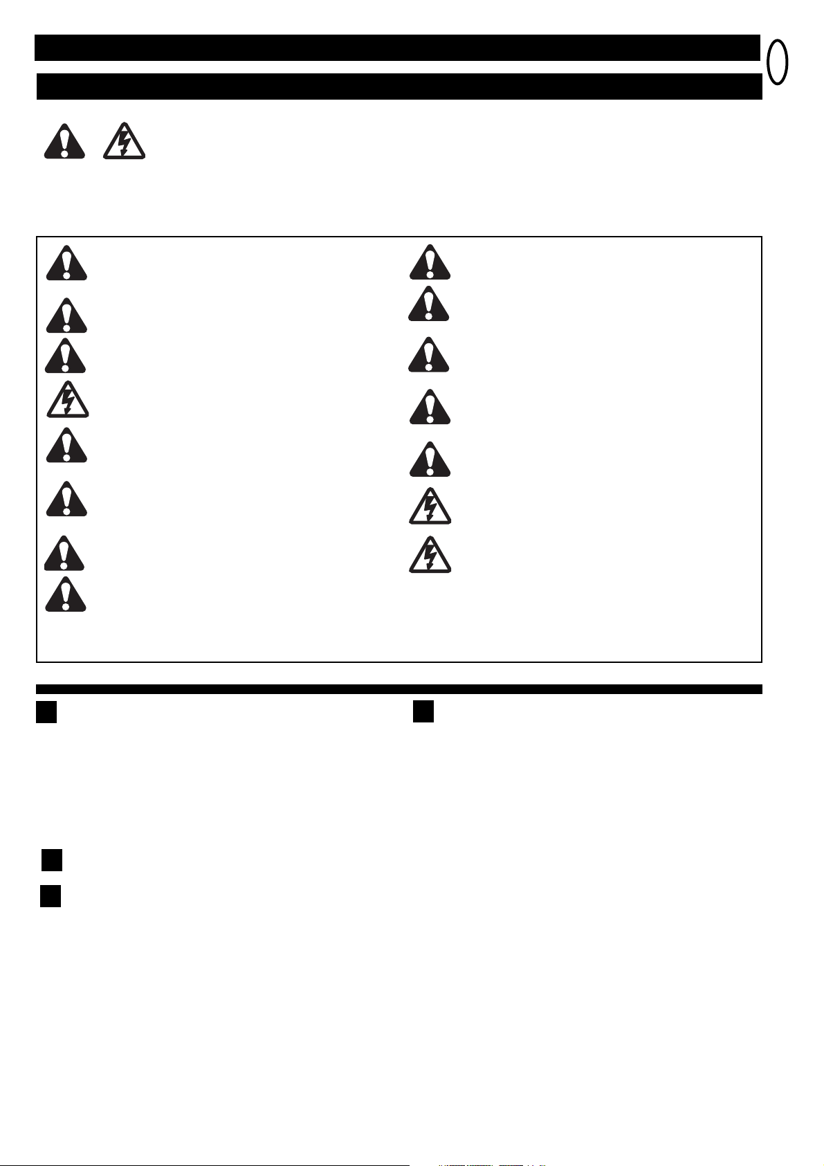
Start by Reading These Important Safety Rules
WARNING: If your garage has no service entrance door, an Outside Quick Release must be installed. This accessory allows
manual operation of the garage door from outside in case of power failure.
Keep garage door balanced. Sticking or binding doors must be
repaired. Garage doors, door springs, cables, pulleys, brackets and
their hardware are under extreme tension and can cause serious
personal injury. Do not attempt to loosen, move or adjust them. Call
for garage door service.
Do not wear rings, watches or loose clothing while installing or
servicing a garage door opener.
To avoid serious personal injury from entanglement, remove all ropes
connected to the garage door before installing the door opener.
Installation and wiring must be in compliance with your local building
and electrical codes. This is a class 2 double insulated product,
connesction to earth is not required or provided.
Lightweight doors of fiberglass, aluminum or steel must be
substantially reinforced to avoid door damage. The best solution is
to check with your garage door manufacturer for an opener installation
reinforcement kit.
The safety reverse system test is very important. Your garage door
MUST reverse on contact with a 40mm obstacle placed on the floor.
Failure to properly adjust the opener may result in serious personal
injury from a closing garage door. Repeat the test once a month and
make any needed adjustments.
This unit should not be installed in a damp or wet space.
Door must not extend over a public byway during
operation.
Fasten the child warning label adjacent to the lighted door control
button as a reminder of safe operating procedures.
Disengage all existing garage door locks to avoid damage to
garage door.
Any door control buttons (if installed) MUST be located where the
garage door is visible, but out of the reach of children. Do not
allow children to operate push button(s) or remote control(s).
Serious personal injury from a closing garage door may result
from misuse of the opener.
Activate opener ONLY when the door is in full view, free of
obstructions and opener is properly adjusted. No one should
enter or leave the garage while the door is in motion. Do not allow
children to play near the door.
Use manual release only to disengage the trolley and, if possible,
ONLY when the door is closed. Do not use the red handle to pull the
door open or closed.
Disconnect electric power to the garage door opener before
making repairs or removing covers.
This product is provided with a transformer and power supply cord of
special design which, if damaged, MUST be replaced by a
transformer from your local Chamberlain Anz distributor and
fitted by a specialist.
SAVE THESE INSTRUCTIONS
ASSEMBLY HARDWARE
1. Square Head Screws (2)
2. 8mm Carriage Bolt (1)
3. Cable Pulley (1)
4. Pin (1)
5. 8mm Lock Nut (1)
6. Pulley Bracket (1)
These safety alert symbols mean WARNING – a personal safety or property damage instruction.
Read these instructions carefully.
This garage door opener is designed and tested to offer reasonable safe service provided it is installed and operated in strict accordance with
the following safety rules.
Failure to comply with the following instructions may result in serious personal injury or property damage.
INSTALLATION HARDWARE
7. 6mm Nut (5)
8. Concrete Anchor (4)
9. 6mm Lag Bolt (4)
10. Clevis Pins (2)
11. 6x25mm Hex Bolt (2)
12. Wire Clips (3)
13. Hex Screws (2)
14. C-rail Bracket (1)
15. Clevis Pins (2)
16. Ring Fastener (4)
17. Flat Washer (1)
18. Anchor (2)
19. Insulated Staples (10)
20. 6x12mm Hex Bolt (1)
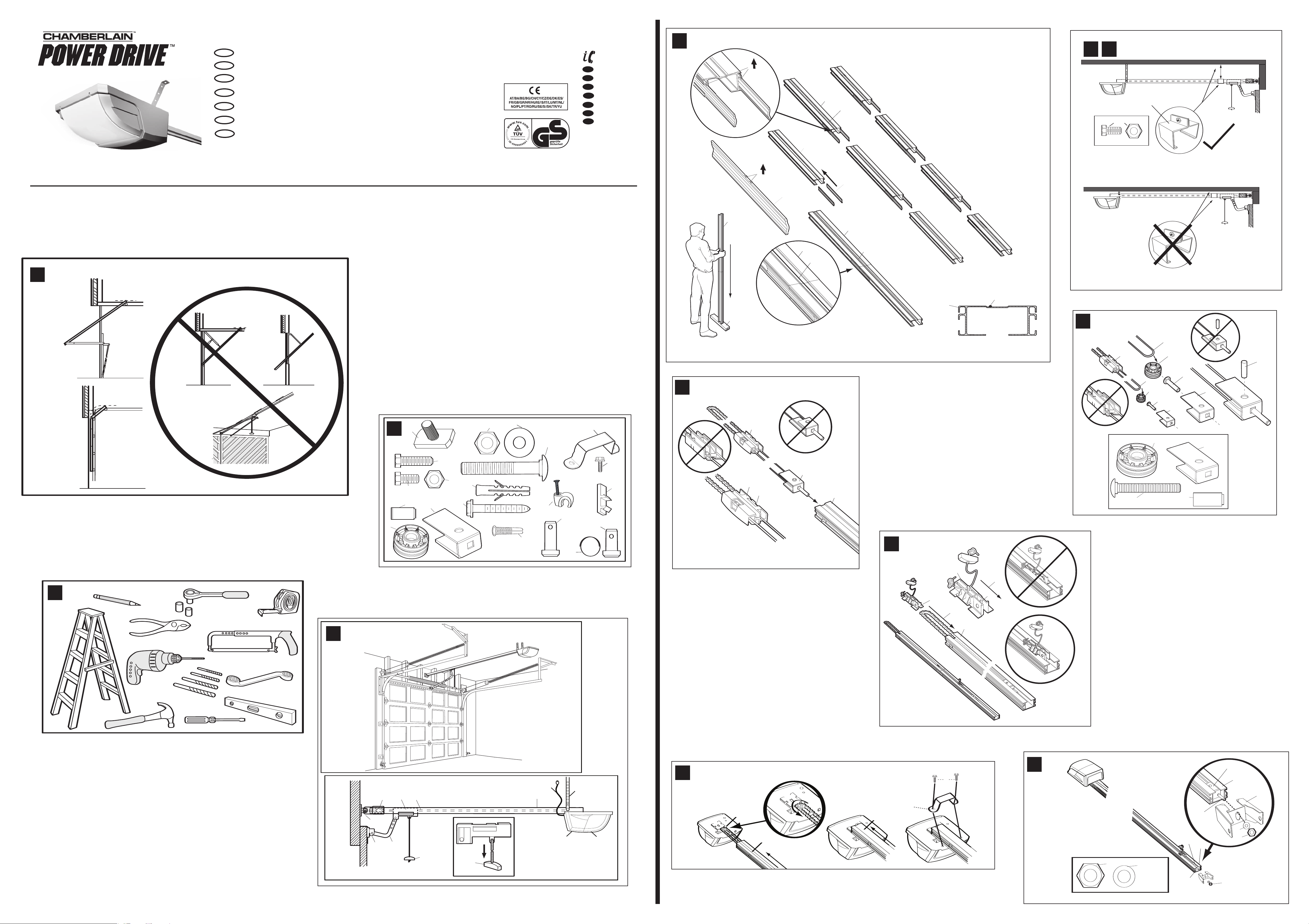
Before You Begin
This operator is suitable for sectional doors.
1. Look at the wall or ceiling above the garage door. The header bracket MUST be
securely fastened to structural supports.
2. Do you have a finished ceiling in your garage? If so, a support bracket and
additional fastening hardware (not supplied) may be required.
3. Do you have an access door in addition to the garage door? If not, an Outside
Quick Release Accessory is required.
Hardware Provided
3
Tools Required for Installation
2
1
CCoommpplleetteedd IInnssttaallllaattiioonn
As you proceed with the assembly, installation and adjustment procedures in
this manual, you may find it helpful to refer back to this illustration of a
completed installation.
4
(1) Cable Pulley Bracket
(2) Trolley
(3) Chain/Cable Assembly
(4) Rail
(5) Hanging Bracket
(6) Power Cord
(7) Opener
(8) Light Lens
(9) Manual Release
Rope & Handle
(10) Door Arm
(11) Door Bracket
(12) Header Bracket
WARNING
Page 3

en-2
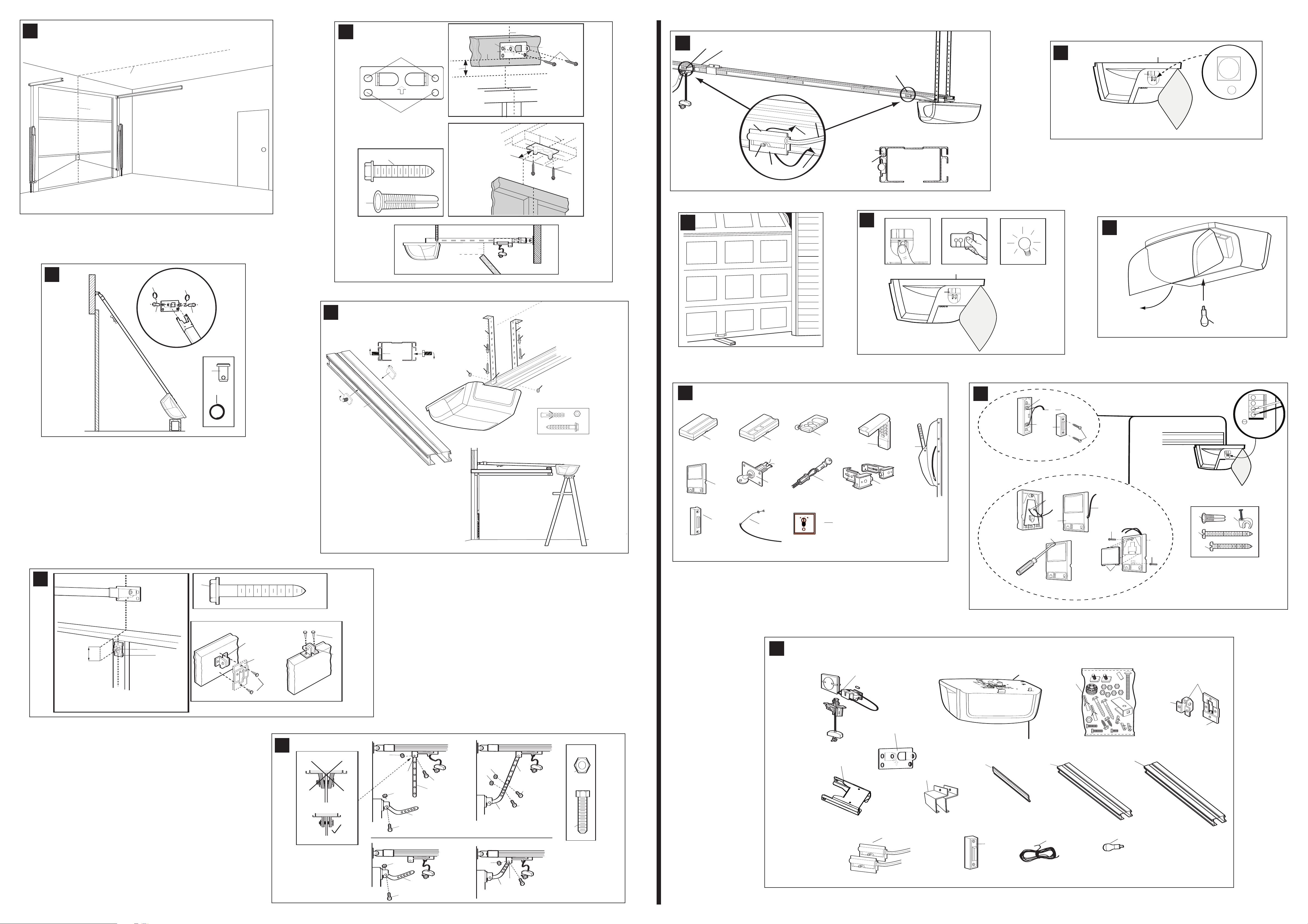
Fasten Door Bracket
Sectional and One-Piece Door Installation Procedure:
Door bracket (1) has left and right side fastening holes. If your
installation requires top and bottom fastening holes use both the door
bracket and door bracket plate (2) as shown.
1. Center door bracket (with or without door bracket plate, as required)
at the top inside face of door as shown. Mark holes.
A.Standard Sectional or One-piece doors: locate bracket at inside
face of the door.
B. Sectional doors with two horizontal roller channels: 150 250mm below the top of the door.
2. A. Sheet metal doors
Fasten with wood screws (4).
B. One-piece door optional
Fasten with wood screws (4).
Connect Door Arm to Trolley
A. Preferred Installation:
Disconnect Trolley by pulling on the red handle and slide towards door. With
door closed connect Straight Door Arm (5) to Trolley (4) with Clevis Pin (6),
secure with Ring Fastener (7). Connect Curved Door Arm (2) to Door Bracket
with Clevis Pin (6) Secure with Ring Fastener (7). Align Straight and Curved
Door Arms with a 2 hole overlap connect with Bolt (3), secure with Nut (1), If
Straight Door Arm (5) is too long, cut the end of the Door Arm.
B. Where extra travel distance is required:
With door closed connect Curved Door Arm (2) to Door Bracket with Clevis Pin
(6), secure with Ring Fastener (7). Lift Curved Door Arm (2) to meet Trolley,
connect door arm to Trolley with Clevis Pin (6), secure with Ring Fastener (7).
Connect Electric Power
To avoid installation difficulties, do not run the garage door opener until
instructed to do so.Plug the opener into electric outlets as specified by local wiring
codes. The opener light will turn on when power is connected and remain on for 21/2 minutes.
16
15
ASSEMBLY SECTION
Assemble Rail
Place Rail pieces (1) on a flat surface for assembly. Take special note of the raised
line on the Rail pieces (4) these lines MUST line up in order for the Rail to fit
together properly. All four Rail sections are interchangeable. Slide Rail Braces (2)
into slots on the sides of Rail. Make sure small tabs on Rail Braces (3) are up
against top lip of Rail. Connect Rail by sliding other end of braces into next Rail. Be
sure the raised lines that run down Rail sections (4) line up. Tap Rail assembly (5) on
a piece of wood (6) until Rail sections are flush. Repeat for final Rail section.
Reinforcement of rail (GPD65)
Install C-rail clamp when clearance between rail and ceiling exceeds 60mm.
Install the C-rail clamp (1) with bolt (2) and nut (3) included at position shown.
(fig.5A)
Position C-rail clamp on the joint of the first and second rail section from the door
closed position and tighten screw.
Make sure the C-rail clamp is located exactly over the joint of both rail sections. The
clamp is for additional reinforcement of the rail and not required when
headroom clearance is less than 60mm.
Assemble Cable Pulley Bracket
IInsert Carriage Bolt (1) though square hole in Cable Pulley Bracket (4). Remove
Chain/Cable assembly (3) from carton. Wrap Cable around Cable Pulley (2) and
insert Pulley into Bracket (NOTE: Make sure the Bracket is assembled in position
shown). Slide pin (5) through holes in Cable Pulley Bracket and Cable Pulley. NOTE:
Trolley with Magnet (6) MUST be installed in the position shown.
Insert Chain/Cable into Rail
Slide Cable Pulley Bracket (1) into Rail assembly (3), be sure to insert Cable Pulley
Bracket as shown. Push Cable Pulley Bracket toward front of Rail and slide Inner
Trolley (2) into Rail assembly. Magnet (4) MUST be installed in position shown or
unit will not function properly.
Attach Trolley to Rail
Turn Rail assembly over. Slide Outer Trolley (1) into Rail assembly (2), be sure the
end with Door Arm Hole (3) is heading in direction of door (4). Slide Outer Trolley
down Rail until it engages with Inner Trolley.
Attach Rail to Unit
Turn Rail assembly over. Wrap Chain around Drive Sprocket (1). Slide Rail assembly
(2) toward unit and into slots on top of unit.
Attach C-Bracket (3) on rail and secure with screws (4) as shown. Push Cable Pulley
Bracket forward making Chain tight on sprocket. Chain MUST engage teeth on Drive
Sprocket.
Attach Rail End Bracket
Turn Rail and Unit assembly over. Slide Cable Pulley Bracket (2) toward front end of
Rail (3). Be careful Chain does not come off Drive Sprocket on unit or become
twisted. Slide Carriage Bolt (5) into Rail End Bracket (1). Secure with Lock Nut (4)
and Washer (6). Tighten Nut until Chain does not droop below rail. Do NOT over
tighten.
ASSEMBLY OF YOUR OPENER IS NOW COMPLETE.
INSTALLATION SECTION
Wear protective goggles when working overhead to protect your eyes from injury.
Disengage all existing garage door locks to avoid damage to garage door. To avoid
serious personal injury from entanglement, remove all ropes connected to garage
door before installing opener.
10
9
8
7
6
5
Attach Rail to Header Bracket
Position opener on garage floor below the header bracket. Use packing material to
protect the cover. Raise rail until holes in the header sleeve and holes in the header
bracket align. Join with clevis pin (1). Insert ring fastener (2) to secure.
NOTE: To enable the rail to clear sectional door springs, it may be necessary to lift
opener onto a temporary support. The opener must either be secured to a support
or held firmly in place by another person.
Hang Opener
Bend Hanging Brackets (1) so they are flat against ceiling. Measure distance from
Header Bracket to Ceiling Mounting Bracket Bolts. Mark length on ceiling starting at
the Header Wall, along this point is where the unit will be mounted. Lift door to full
open position, rest opener on door. Insert Square Head Screws (A) into Rail
assembly (B) approximately 120mm from end of Rail near motor unit. Slide Hanging
Brackets on to Square Head Screws and secure Brackets with Nuts (5). In this
process the Square Head Screws hook into slots on the sides of rail. (C)
For concrete ceilings, drill 8mm pilot holes into ceiling and insert Concrete Anchors
(2). Secure Hanging Brackets to ceiling with Lag Screws (3). For wood ceilings, drill
4mm pilot holes and secure with Lag Screws (3).
Optional: A second set of hanging brackets is recommended when door is very
heavy. The hanging brackets should be located in the first third to the center of the
rail from the front or at the location the garage door opener lifts the rail upwards the
most during the travel.
13
Install the Header Bracket
NOTE: Refer to vertical center and horizontal lines created in step 11 for
proper placement of header bracket.
A. Wall Mount: Center the header bracket (1) on the vertical center line (2) with the
bottom edge of the header bracket on the horizontal line (4) (with the arrow
pointing toward the ceiling). Mark all of the header bracket holes (5). Drill 4,5 mm
(3/16") pilot holes and fasten the header bracket with wood screws (3).
B. Ceiling Mount: Extend vertical center line (2) onto the ceiling. Center the header
bracket (1) on the vertical mark no more than 150 mm (6") from the wall. Make
sure the arrow is pointing toward the opener. Mark all of the header bracket holes
(5). Drill 4,5 mm (3/16") pilot holes and fasten the header bracket with wood
screws (3). For concrete ceiling mount, use concrete anchors (6) provided.
Clearance between highest point of travel and Rail should not exceed 50mm
and can be zero when clearance between door and ceiling is only 30mm.
12
Find Center of Garage
Mark center of door (1). Extend line onto ceiling (2).
11
14
Page 4

en-3
Replace Light Bulb
Replace light bulb (1) with a 21 watt maximum light bulb. Insert bulb into socket as
shown. The light will turn on and remain lit for 2 1/2 minutes when power is
connected. After 2 1/2 minutes it will turn off.
21
Test the Safety Reverse System
The safety reverse system test is important. Garage door must reverse on
contact with a 40mm obstacle laid flat on the floor. Failure to properly adjust
opener may result in serious personal injury from a closing garage door.
Repeat test once a month and adjust as needed.
Procedure: Place a 40mm obstacle (1) laid flat on the floor under the garage door.
Operate the door in the down direction. The door must reverse on the obstruction.
If the door stops on the obstruction, it is not traveling far enough in the down
direction. Move Close Limit closer to door.
When the door reverses on the 40mm obstacle, remove the obstruction and run the
opener through a complete travel cycle. Door must not reverse in closed position. If
it does, adjust Limit and repeat safety reverse test.
Place 20kg at the center of the door and ensure that the door will not move up more
than 500mm.
SAVE THESE INSTRUCTIONS
19
Program Remotes
Activate the opener only when door is in full view, free of obstruction and
properly adjusted. No one should enter or leave garage while door is in
motion.
Your garage door opener receiver and Remote Control Transmitter are set to a
matching code. If you purchase additional Remote Controls, the garage door opener
must be programmed to accept the new Remote code.
To program receiver to match additional Remote Control codes:
1. Press and release the program button on the side of the unit (1). The green LED
will glow steadily for 30 seconds.
2. Within 30 seconds press and hold the button on the hand-held Remote (2).
3. Release the button when the motor unit light blinks. It has learned the code. If the
light bulb is not installed, two clicks will be hear.
To erase all codes from motor unit memory or to deactivate any unwanted
Remote, first erase all codes:
Press and hold the program button (1) on motor unit until the learn indicator light
goes out (approximately 6 seconds). All previous codes are now erased. Reprogram
each Remote or Keyless Entry you wish to use.
20
Operation Of Your Opener
Your opener can be activated by any of the following devices:
• The Remote Control Transmitter. Hold the push button down until the door starts to
move.
• The Lighted Door Control Button (if you have installed this accessory). Hold the
button down until door starts to move.
• The Outside Keylock or Keyless Entry System (if you have installed either of these
accessories).
Opening the Door Manually:
Door should be fully closed if possible. Weak or broken springs could allow an open
door to fall rapidly. Property damage or serious personal injury could result.
The door can be opened manually by pulling the release handle down. To reconnect
the door, activate the unit.
Do not use the manual release handle to pull the door open
or closed.
When the Opener is Activated by Remote Control or Door Control Button:
1. If fully open, the door will close.
2. If closed, the door will open.
3. If opening or closing, the door will stop.
4. If partially open, the door will move in the opposite direction of last travel.
5. If an obstruction is encountered while closing, the door will reverse to the open
position.
6. If an obstruction is encountered while opening, the door will reverse for 1 second.
7. The optional Protector System™ uses an invisible beam which, when broken by
an obstruction, causes a closing door to open and prevents an open door from
closing. It is STRONGLY RECOMMENDED for homeowners with young children.
Allow a 15 minute cooling period after 5 continuous operations of the opener.
The opener light will turn on: 1. when opener is initially plugged in;
2. when the power is interrupted; 3. when the opener is activated.
The light turns off automatically after 2-1/2 minutes. Bulb size is
21 Watts maximum.
Setting the Force
The Force is programmed to operate most doors, however, if Limits are not able to
be set, or the door reverses during normal operation follow this procedure: Locate
the Program Button (1) on the left side panel of unit (2). Push the Program Button
twice to enter unit into Auto-Force Adjustment Mode. The green LED will flash
slowly. Activate unit with remote and run the unit to the Open Limit. Activate unit
again to run the unit to the Closed Limit. The door must travel through a complete
cycle up and down in order for the Force to be set properly. If the unit stops before it
reaches the Open or Close Limit repeat the process. The green LED will stop
flashing when the Force has been learned.
18
Attach Limit Switches
NOTE: The limits must be installed as shown. If installed incorrectly the unit will not
function properly.
Close garage door by hand. Determine the position of the Close Limit Switch (1)
(Long wire) by aligning the center of trolley and the center of the Limit Switch. The
Limit Switches are actuated by a magnet in the Inner Trolley. Insert bottom tab (5) of
Limit Switch (1) into bottom lip of Rail (7). Insert top tab (4) under top lip of Rail (6).
Lift limit assembly against top lip of Rail and tighten screw (8) to secure Close Limit
Switch. Open garage door by hand to the full open position. Pull red handle to open
door past Inner Trolley. Determine the position of the Open Limit Switch (3) (Short
Wire) by aligning the center of the Trolley and the center of the Limit Switch. Insert
bottom tab (5) of Limit Switch (1) into bottom lip of rail (7). Insert top tab (4) under
top lip of rail (6). Lift limit assembly against top lip of rail and tighten screw (8) to
secure Open Limit Switch. Insert wires for Limit Switch (9) into top channel of Rail
(10). Secure wires with wire clip. the wires must be secured so they do not interfere
with the travel of the Trolley. Activate remote, the opener will operate and reconnect
to the door automatically. Run opener 2 full travel cycles. If the door reverses in mid
travel go to Setting the Force Section. Adjust Limit Switches as necessary to fully
open and close the door without reversing.
17
Page 5

en-4
7. Door opens but won’t close:
• Check The Protector System™ (if you have installed this accessory). If the light
is blinking, correct alignment.
Repeat the safety reverse test after the adjustment is complete.
8. Opener light does not turn on:
Replace light bulb (21 Watts maximum).
9. Opener light does not turn off:
Defective logic board.
10. Opener motor hums briefly, then won’t work:
• Garage door springs are broken. Close door and use Manual Release Rope
and handle to disconnect Trolley. Open and close door manually. A properly
balanced door will stay in any point of travel while being supported entirely by
its springs. If it does not, call for a professional garage door service to correct
the problem.
• If problem occurs on first operation at opener, door may be locked. Disable
door lock.
11. Opener won’t activate due to power failure:
• Pull Manual Release Handle to disconnect Trolley. Door can be opened and
closed manually. The next time opener is activated, the Trolley will reconnect.
• The Outside Quick Release accessory 1702EMLM (if fitted) disconnects the
Trolley from outside the garage in case of power failure.
12. Door reverses after the force adjustment was completed.
• Watch rail if it bends. If so, see point 13+14.
• Door is very heavy and/or in bad condition. Call for professional garage door
service.
13. Rail bends a lot
• Use rail clamp. (see section 5A)
• Garage door is very heavy or in bad condition. Call for professional garage door
service.
14. Do I need to use the rail clamp?
• Avoids bending of rail.
15. Opener light flares
• When the garage door is very heavy or isn’t smooth running.
>> Normal
16. Opener overrides one of the limit switches
• Limit switches are not installed at the correct side of the rail and/or in the
location. See “Attach Limit Switch”
• A functional test of the rail contact (cable) can be made with a simple
household magnet.
• Check condition of cables for insulation damages
• Check if the magnet located inside the inner trolley is in place
HAVING A PROBLEM?
1. Opener doesn’t operate from remote:
• Does the opener have electric power? Plug lamp into outlet. If it doesn’t light,
check the fuse box or the circuit breaker. (Some outlets are controlled by a wall
switch.)
• Have you disengaged all door locks? Review installation instruction warning on
page 1.
• Try a new battery.
• If you have two or more remotes and only one operates, review receiver
programming procedures in Step 21.
• Is there a build-up of ice or snow under door? The door may be frozen to
ground. Remove any obstruction.
• The garage door spring may be broken. Have it professionally replaced.
2. Remote has short range:
• Is battery installed? Try a new one.
• Change the location of the remote control in the car.
• The metal garage door, foil-backed insulation or metal siding will reduce the
transmission range.
3. Door reverses for no apparent reason and opener lights don’t blink:
• Is something obstruction the door? Pull Manual Release Handle. Operate door
manually. If it is unbalance or binding, call for professional garage door service.
• Reprogram the Force.
• Clear any ice or snow from garage floor area where garage door closes.
• If door reverses in fully closed position, adjust the Close Limit.
Repeat safety reverse test after adjustment is complete.
The need for occasional adjustment of the Limit positions is normal. Weather
conditions in particular can affect door travel.
4. Door reverses for no apparent reason and door control button light blinks
for 5 seconds after reversing:
• Check The Protector System™ (if you have installed this accessory). if the light
is blinking, correct alignment.
5. The garage door opens and closes by itself:
• (Keypad or Code Switch transmitters only) Is there a neighbor with a garage
door opener using the same code? Change your code.
• Make sure remote push button is not stuck in ON position.
6. Door does not close completely:
Adjust the Close Limit.
Repeat safety reverse test after any adjustment of door arm length, or Close
Limit.
Care Of Your Opener
When properly installed, opener will provide high performance with a minimum of
maintenance. The opener does not require additional lubrication.
Limit and Force Adjustments: These adjustments must be checked and properly
set when opener is installed. Only a screwdriver is required to adjust the
limits. Weather conditions may cause some minor changes in the door operation,
requiring some re-adjustments, particularly during the first year of operation.
Refer to the Limit and Force Adjustments on page 2. Follow the instructions carefully
and repeat the safety reverse test after any adjustment.
Remote Control Transmitter: Additional Remotes can be purchased at any time
for use in all vehicles using garage. Refer to Accessories.The receiver must be
programmed to operate with any new Remote.
Remote Control Battery: The lithium batteries should produce power for up to 5
years. If transmission range lessens, replace battery.
To Change Battery: Insert batteries positive side up. To replace cover, snap shut
along both sides. Do not dispose of the old battery with household waste. Take
batteries to a proper disposal center.
Maintenance Of Your Opener
Once a Month:
• Repeat safety reverse test. Make any necessary adjustments.
• Manually operate door. If it is unbalanced or binding, call for professional garage
door service.
• Check to be sure door opens and closes fully. Adjust Limits and/or Force if
necessary.
Twice a Year:
• Check chain tension. Disconnect Trolley first. Adjust if necessary.
Once a Year:
Oil door roller, bearings and hinges. The opener does not require additional
lubrication. Do not grease the door tracks.
Page 6

Replacementparts
1. 041A5644 Trolley with chain/cable assy (GPD60)
001A6355-3 Trolley with chain/cable assy (GPD65)
2. 001A5690-35 Head only (GPD60)
001A5690-36 Head only (GPD65)
3. 001A5643-6 Hardwarebag
4. 012B0905 Door bracket
012B0906
5. 012C0908 Rail end bracket
6. 012C0788 Header bracket
7. 001B0911 C-rail clamp (GPD65)
8. 05765 Rail hardware
9. 183D0181-3 Rail parts (GPD65)
10. 041A5676 Rail parts (GPD60)
11. 041C0521-1 Limit switch (GPD60)
041A0521-2 Limit switch (GPD65)
12. 001A4166 Push button
13. 001B4494-1 Wire
14. 041A0079 Lightbulb
24
en-5
Accessories
(1) Model 84330EML Single-Function Remote Control
(2) Model 84333EML 3-Function Remote Control
(3) Model 84335EML 3-Function Mini Remote Control
(4) Model 8747EML Keyless Entry System
(5) Model 845EML Multi-Function Door Control Panel
(6) Model 760EML Outside Keylock
(7) Model 1702EML Outside Quick Release
(8) Model 770EML The Protector System™
(9) Model 1703EML The Chamberlain Arm™
(10) Model 75EML Lighted Door Control Button
(11) Model 1EML Door Handle Quick Release
(12) Model 41EML 2 Position Key Switch
NOT SHOWN:
Model MDL100EML Mechanical Door Latch
WIRING INSTRUCTIONS FOR ACCESSORIES
Outside Keylock – To opener terminals: Red-1 and White-2
Protector System™ – To opener terminals: White-3 and Grey-4
Door Control Panel – To opener terminals: Red-1 and White-2
22
Wiring the Lighted Door Control Button
(Optional)
Locate any Wall Mounted Door Control where the garage door is visible, away
from door and door hardware, at a minimum height of 1.5m. fasten the child
warning label on the wall near the Door Control.
There are 2 screw terminals (1) on the back of the Door Control (2). Strip about
6mm of insulation from bell wire (4). Separate wires enough to connect the white/red
wire to terminal screw 1 and the white wire to terminal screw (1)
Lighted Door Control Button: Fasten to an inside garage wall with sheet metal
screws (3) provided with Lighted Push Button. Drill 4mm holes and use anchors (6)
if installing into drywall or concrete. A convenient place is beside the service door
and out of reach of children.
Run the bell wire up the wall and across the ceiling to the garage door opener. Use
insulated staples (5) to secure wire.
The opener Quick-Connect Terminals (7) are located in the recess next to the learn
button on the left side panel. Insert bell wire into holes in the Quick Connect
Terminals as follows: Red/White to Red and White to White.
Install Protector System™
(Optional) – (See accessories)
After opener has been installed and adjusted, The Protector System™ accessory
can be installed. Instructions are included with this optional device.
The Protector System™ provides an additional measure of safety against a
small child being caught under a garage door.
It uses an invisible beam which, when broken by an obstruction, causes a closing
door to open and prevents an open door from closing and is strongly recommended
for homeowners with young children.
23
Specifications
Input Voltage . . . . . . . . . . . . . . .230 VAC 50Hz
Max. Pull force . . . . . . . . . . . . . .600N (GPD60), 650N (GPD65)
Rated Power Input . . . . . . . . . . .85 Watts
Rated Load . . . . . . . . . . . . . . . .3.0 Nm
Standby Power . . . . . . . . . . . . . .9 Watts
Max. Door Weight . . . . . . . . . . .60kg (GPD60), 80kg (GPD65)
Motor
Type . . . . . . . . . . . . . . . . . . . . . .63:1 Worm Gear Reduction
Volts . . . . . . . . . . . . . . . . . . . . . .24VDC
Drive Mechanism
Length of Travel . . . . . . . . . . . . .2,3 m (GPD60), 2,5 m (GPD65)
Travel Rate . . . . . . . . . . . . . . . .8cm/sec
Lamp . . . . . . . . . . . . . . . . . . . . .24V 21 Watts
Safety
Electronic . . . . . . . . . . . . . . . . . .Auto-Force Adjustment
Electrical . . . . . . . . . . . . . . . . . .Thermal Fuse in Transformer
Limit Adjustment . . . . . . . . . . . . .Manual
Dimension
Length (Overall) . . . . . . . . . . . . .2,75 m (GPD0), 3,05 m (GPD65)
Headroom Required . . . . . . . . . .30mm
Hanging Weight . . . . . . . . . . . . .9kg (GPD60), 9,5kg (GPD65)
Receiver Code Registers
Rolling Code . . . . . . . . . . . . . . .8
Operating Frequency . . . . . . . . .433.92MHz
Declaration of Conformity
The undersigned, hereby declare that the equipment specified, and all
accessories, conforms to the Directives and Standards stated.
Model:....................................................................................GPD60/GPD65
2004/108/EC
2006/95/EC
1999/5/EC
EN55014-1 (2000), EN55014-2 (1997), EN61000-3-2 (2000), EN61000-3-3
(1995), EN 301 489-3 (V1.3.1), EN 300 220-3 (V1.1.1), EN60335-1 (1994),
and EN60335-2-95 (2000)
Declaration of Incorporation
A power door operator, in combination with a Garage Door must be installed
and maintained according to all the Manufacturer’s instructions, to meet the
provisions of EN12453, EN13241-1 and Machinery Directive, 98/37/EG.
B. P. Kelkhoff
Manager, Regulatory Affairs
Chamberlain GmbH
D-66793 Saarwellingen
January, 2009
Page 7

Page 8

Page 9

114A3909 © 2009, Chamberlain GmbH, All rights reserved
Page 10
A
1
0
1
1
B
1
3
1
4
2
0
4
3
5
2
6
7
8
9
10
11
12
1
13
14
15
16
17
18
19
6
5
8
7
NOTIC
E
9
1
2
3
4
9
10
11
12
1
1
1
4
4
5
5
4
6
2
2
5
4
3
3
GPD65
GPD60
1
2
3
1
2
3
1
2
4
4
3
1
2
5
1
2
4
3
6
5
1
2
3
2
4
1
2
1
3
4
4
1
2
2
3
4
3
5
4
1
3
2
4
1
3
2
5
4
5
2
2
3
5
4
4
4
3
6
6
1
de
e
n
(+44) 0800 317847
n
l
(+31) 020.684.79.78
f
r
d
e
(
+49) 06838-907-100
(+33) 03.87.95.39.28
i
t
e
s
(+34) 902 88 33 79
(+39) 02 303 52006
pt
7
07 785 454
2
1
A
1
0
11
B
1
3
1
4
f
en
e
i
Abbildungen – Garagentorantriebe GPD60, GPD65
r
Figures – Modèles GPD60, GPD65 de ouvre-porte de garage
llustrations – Garage Door Operator Models GPD60, GPD65
I
s
lustraciones – Abridor de la puerta de garage, Modelo GPD60, GPD65
I
t
llustrazioni – Apriporta per garage Modelli GPD60, GPD65
I
Chamberlain GmbH
lfred-Nobel-Str. 4
A
66793 Saarwellingen
D
www.chamberlain.de
5
5 A
(
GPD65)
1
nl
p
t
fbeeldingen – Modellen GPD60, GPD65 Garagedeuropener
A
Instruções – Operador automático de porta, Modelo GPD60, GPD65
6
7
3
2
8
4
10
9
Page 11
5
2
3
A
B
C
5
3
2
1
4
5
3
2
1
1
2
A. 0-100mm
B. 150-250mm
4
1
4
1
2
4
2
3
A
B
1
3
A
B
4
2
2
3
1
1
5
2
4
5
3
2
3
1
1
3
1
1
3
1
4
5
8
6
7
2
9
1
0
3
9
1
2
1
.
2.
3.
2
1
1
L
O
C
K
L
IG
H
T
8
8
4
2
3
1
W
HT
2
R
ED
1
1
2
1
RED
WHT
L
O
C
K
LI
G
HT
1
2
3
5
6
8
9
10
4
L
O
C
K
L
I
G
HT
GPD65
GPD60
7
1
3
5
4
6
7
012B0905
012B0906
012C0908
012C0788
001B0911
(GPD65)
8
05765
2
9
183D0181-3
001A6355-3
(4-piece rail, GPD65)
001A5643-6
10
11
12
001A4166
001B4494-1
GPD60 (4x)
GPD65 (6x)
GPD65 (4x)
14
041A0079
GPD60 (3x)
041A5644
3-piece rail, GPD60
001A5690-35
(GPD60)
001A5690-36
(GPD65)
041A0521-2
(4-piece rail, GPD65)
041C0521-1
(3-piece rail, GPD60)
041A5676
13
1
2
2
1
1
2
1
2
11
2
5
0mm
(
2")
3
1
4
B
A
3
6
150mm
(6")
1
2
3
5
5
5
5
5
5
50mm
9
6
8
7
5
845EML
1703EML
770EML
1702EML
760EML
4
8747EML
84335EML
3
1
2
1EML
34EML/41EML
84333EML
2
84330EML
1
L
OC
K
LIG
H
T
11
75EML
1
0
1
2
17
1
8
13
14
19
20
21
22
23
15
24
16
14A3568B
1
 Loading...