

Page 1
GB-1
START BY READING THESE IMPORTANT SAFETY RULES
Handle tools and hardware carefully and do not
wear rings, watches or loose clothing while
installing or servicing a gate opener.
I
nstallation and wiring must be in compliance with
your local building and electrical codes. Connect
the power cord only to properly earthed mains.
Keep additional accessories out of the reach of
children. Do not allow children to operate push
button(s) or remote control(s). Serious personal
injury from a closing gate may result from misuse of
the opener.
Disconnect electric power to the gate opener
before making repairs.
Disengage all existing gate locks to avoid damage
to gate opener.
Keep gate balanced. Sticking or binding gates must
be repaired. Do not attempt to repair the gates
yourself. Call for service.
CAUTION: Activate opener only when the gate is
in full view, free of obstructions and opener is
properly adjusted. Do not allow children to play
near the gate.
Ensure that persons who install, maintain or
operate the gate opener follow these instructions.
Keep this manual where it can be readily referenced
during maintenance.
These safety alert symbols mean Caution – a personal safety or property damage instruction. Read these
instructions carefully.
This gate opener is designed and tested to offer reasonable safe service provided it is installed and operated
in strict accordance with the following safety rules.
Failure to comply with the following instructions may result in serious personal injury or property damage.
Content
Safety rules: Page 1
Technical Data: Page 1
Warranty: Page 1
Electronic control with connections: Illustration
Elektrical Installation: Page 2, Illustration
Force adjustment: Page 3
Safety: Page 3, Illustrations -
Combined Operation: Page 3
Initial Operation: Page 4
Initial setting of Remot control: Page 4, Illustration
Accessories & Replacement parts: Page 4, Illustration
TECHNICAL DATA
Power supply. . . . . . . . . . . . . . . . . . . . . 230V/50-60Hz
Absorbed power. . . . . . . . . . . . . . . . . . . 4W
Max. load . . . . . . . . . . . . . . . . . . . . . . . . 1100W
Protection fuses. . . . . . . . . . . . . . . . . . . 1 (5A)
Housing degree of protection . . . . . . . . . . . IP54
WARRANTY
LIFTMASTER warrants to the first retail purchaser of this product
that the product shall be free from any defect in materials and/or
workmanship for a period of 24 full months (2 years) from the date
of purchase for the Electronic Control. Upon receipt of the product,
the first retail purchaser is under obligation to check the product for
any visible defects.
Conditions: The warranty is strictly limited to the reparation or
replacement of the parts of this product which are found to be
defective and does not cover the costs or risks of transportation of
the defective parts or product.
This warranty does not cover non-defect damage caused by
unreasonable use (including use not in complete accordance with
LIFTMASTER's instructions for installation, operation and care;
failure to provide necessary maintenance and adjustment, or any
adaptations of or alterations to the products), labor charges for
dismantling or reinstalling of a repaired or replaced unit or
replacement batteries.
A product under warranty which is determined to be defective in
materials and/or workmanship will be repaired or replaced (at
LIFTMASTER's option) at no cost to the owner for the repair and/or
replacement parts and/or product. Defective parts will be repaired or
replaced with new or factory rebuilt parts at LIFTMASTER's option.
This warranty does not affect the purchaser's statutory rights under
applicable national legislation in force nor the purchaser's rights
against the retailer arising from their sales/purchase contract. In the
absence of applicable national or EC legislation, this warranty will be
the purchaser's sole and exclusive remedy and neither LIFTMASTER
nor its affiliates or distributors shall be liable for any incidental or
consequential damages for any express or implied warranty relating
to this product.
No representative or person is authorized to assume for LIFTMASTER
any other liability in connection with the sale of this product.
The LiftMaster control unit can be used with any common
230V gate openers. However, LiftMaster cannot give any
warranty for trouble-free operation if the unit is not connected
up according to specifications.
8
7
3 6
1
2
Page 2
GB-2
ELEKTRICAL INSTALLATION
The electronic control unit supplied is required for operation
of the wing gate actuator. This control unit comprises an
electronic microprocessor-control system employing the latest
technology. It may be used for the connection of 1 or 2
motors and offers all connection possibilities and functions
necessary for safe and reliable operation.
The electrical connections for single- or double gates are
given in Illustration 2.
The control box containing the motor control module is to be
fitted with cable entry at bottom. It should not be continuously
exposed to direct sunlight. For weather protection, we
recommend the fitting of a small protection roof.
Thanks to the electronic control unit, fine adjustment of the
push-pull torque is possible. When correctly adjusted, gate
movement can be easily blocked by hand.
For the OPEN and CLOSED positions, the gate requires a
stable end stop as the swing gate actuator unit is not
fitted with limit switches and the electronic controls are
switched off by time.
CONNECTION OVERVIEW
The control unit should be connected up last, i.e. after the
motor has been mounted, the necessary cables laid and the
Infrared Sensors or contact strips fixed in place.
In the case of permanent mounting, means of separating the
system from the mains must be provided. The contact
spacing of the main switch used in this connection must be at
least 3 mm.
NOTE:
In these instructions, relay contacts are designated as
NC (normally closed) and NO (normally open).
• NC contacts are closed, and open when actuated
• NO contacts are open, and close when actuated
2
ELECTRONIC CONTROL WITH CONNECTIONS
1
TERMINAL
PE
PE
PE
C1
1
2
3
C1
C2
4
5
6
C2
7
8
9
10
11A
12A
13A
14A
15A
16A
17A
11B
12B
13B
14B
15B
16B
17B
OVERVIEW
DESCRIPTION
Earth supply cord
Earth motor 1
Earth motor 2
Capacitor motor1
Direction CLOSED (L1.1) motor 1
MP
Direction OPEN (L1.2) motor 1
Capacitor motor 1
Capacitor motor 2
Direction CLOSED (L1.1) motor 2
MP
Direction OPEN (L1.2) motor 2
Capacitor motor 2
Flashing light MP 230Volt
˜
Flashing light L1 230Volt
˜
E-lock drive NO
E-lock drive NO
Safety input OV (socket module 1)
Safety input +24V (socket module 1)
Switching input 1 (socket module 1)
Limit switch contact 1 (factory bridged)
Limit switch contact 1 (factory bridged)
Push button motor 1 only, NO
Push button motor 1 only, NO
Safety input 0V (socket module 2)
Safety input +24V (socket module 2)
Switching input 2 (socket module 2)
Limit switch contact 2 (factory bridged)
Limit switch contact 2 (factory bridged)
Push button motor 1 + 2 NO
Push button motor 1 + 2 NO
Page 3

GB-3
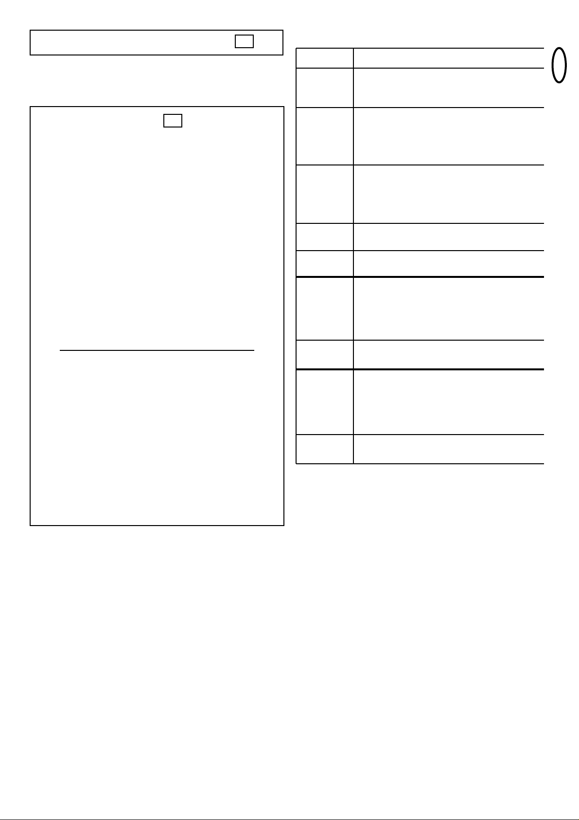
FUNCTION AND DESCRIPTION OF DIP SWITCHES
FUNCTION AND DESCRIPTION OF POTENTIOMETERS
DESCRIPTION OF LEDS
Note: If both LED’s turn off when operating the limit switch,
the cables will have to be changed.
FORCE ADJUSTMENT AND AUTOMA TIC SWITCH OFF
The drive force of the motors is adjusted with potentiometers
M1 and M2. The control unit has an automatic force shut-off. If
the gate encounters an obstacle during operation, it stops. The
force required to stop a door and to actuate shut-off increases
as potentiometers M1 and M2 are set to higher values.
The force shut off feature is not generally used in outdoor
installations. Gates which are large, heavy or move
sluggishly should not have a drive with force shut off, as this
feature could be actuated e.g. by strong winds. Unplug the
cable leading from the force module in order to interrupt the
force shut off.
After a force shut off, door 2 should always be closed first in
order to ensure correct closure of a 2 leaf gate.
The force shut off may not be used as the only safety
measure. Other safety measures, based on use of Infrared
Sensor, Contact Strips etc. must also be used.
OPERATION WITHOUT SAFETY MODULE
Unplug the two safety modules and replace the control unit.
The control unit’s internal test routine indicates that the
modules are not being used, and the control unit is not
blocked
Operation without safety devices is dangerous, and is
not permitted.
DEAD MAN’S OPERATION
In the dead man’s-mode of operation, a gate can be used
without safety devices if the operator has a full overview of
the system’s operation.
Three dip switches are situated in the top part of the control
unit. Set dip switch 3 to ON. The control unit then only
functions while continuous control signals are given by
means of a transmitter, key or pushbutton. If the control
signals are interrupted, the gate stops and will move in the
opposite direction when the next signal is received.
OPERATION WITH INFRARED SENSOR TYPE
LIFTMASTER 770E AND SAFETY MODULE 801689
When connecting this IR Sensor a permanent examination of
the IR Sensor and the according cables is granted. The
IR Sensor is failsafe and is in accordance to the regulations
to connect only cables with the same markings (white/white
11A/11B and black/black 13A/13B).
OPERATION WITH INFRARED SENSOR
TYPE LIFTMASTER 100236 AND
SAFETY MODULE 801696
The IR Sensor will be connected with the 8.2 KΩ restitor
(which is included). The connection of 2 IR Sensors is
possible through serial connection (terminals 3 and 4 of the
IR Sensors and the 8.2 KΩ restitor are connected in series)
(Safety inputs 11-12-13A/B).
OPERATION WITH CONTACT STRIPS
AND MODULE 801696
The contact strips work in the same way as photoelectric
barrier type LifMaster 100263. With self-monitoring strips
which have their own control unit, e.g. light strips, the
8.2 Kohm test resistor should be clamped in the lead. With
non-self-monitoring contact strips, it is advisable to clamp the
test resistor to the end of the strip to permit full testing of the
strip Several contact strips can be used in series. Connection
to 11B/13B (socket module 2)
FEELER FOR WING 1 (MOTOR 1)
FEELER FOR WINGS 1 + 2 (MOTOR 1 + 2)
COMBINED OPERATION WITH CONTACT STRIPS AND
INFRARED SENSOR
Each one of the two safety inputs works independently. They
can be configured in any desired way to meet requirements.
LiftMaster drives WGO300 and WGO400 do not require a limit
switch for proper functioning. If it sufficient to provide a sturdy
stop on the floor, so that the gate always moves the same
distance. The contacts have jumpers fitted at the factory.
ELECTRIC LOCKS: In order to permit the use of various
electro-lock systems, contact 9-10 is designed for potential free
closure. The contact is closed 1 second before the motor starts
up, and stays in this condition for about 3 seconds. In other
words, the lock is unlocked before the door opens and remains
actuated for 3 seconds to ensure that it does not get locked
again. This function is also operative during closure of the gate.
6
5
4
3
SAFETY SAFETY MODULE
The type of safety model used depends on the kind of
protection required. The safety module isused to evaluate
and function test the safety devices employed in accordance
with ZH1 494 and CEN.
801689 module for LiftMaster Infrared Sensor 770E. 801696
module must be used with Infrared Sensor 100263 or a
Contact Strip. An 8.2 Kohm test resistor is required in this
connection (this is supplied along with the module).
63
Dip switch 1 ON - IR Sensor
OFF - Contactstrip
only for socket module 2 in
connection with module 801696
Dip switch 2 ON - Reversal to direction “OPEN”
after recognizing the obstacle
OFF - Stop - after recognizing the
obstacle
Dip switch 3 ON = Dead man’s operation on
OFF = Dead man’s operation off
Potentiometer 1 Operating times up to 45 seconds
(safety function only, i.e. set to longer than
actually required)
Potentiometer 2 Delay operation of second door up to
120 seconds
Potentiometer 3 Automatic admission up to 120 seconds
LED1 Impulse to M1+M2 on: Impulse
off: no Impulse
LED2 Impulse to M1 on: Impulse
(Pedestrian-Function) off: no Impulse
LED3 Limit switch
LED turns off when limit switch is operated
LED4 Limit switch
LED turns off when limit switch is operated
Page 4

GB-4
DELETION OF PROGRAMMED
REMOTE-CONTROL CODES
Press the corresponding learn button (1 or 2) approx. 10 sec.
on the receiver PCB until the learn LED goes off. The code
memorised with this learn button has now been deleted.
REPROGRAMMING
When reprogramming, the above-mentioned coding steps must
be repeated for all remote-control handsets in operation and
their control buttons. The operating range of the remote-control
unit depends on local conditions. Press and hold the button on
the handset (approx. 2 seconds) until the gate begins to move.
In the PTT-approved frequency range for the radio control of
gates, there are also medical, industrial, scientific, military and
household radio systems in operation, some of which have a
very high transmission range. The close proximity of such a
radio installation could lead to a reduction in operating range or
temporary interference in your radio remote-control system.
INITIAL OPERA TION AND TRANSFER
• Connect up the control unit including the safety inputs
• Connect up the gate and lock the motors
• Connect the control unit to the mains
• Check whether any of the LEDs of the safety module have
lit up; this indicates that the control unit has been blocked
because one of the safety devices has been triggered
• Have the limit switches been jumpered? (This should be
done in the factory for 14A and 15A, and for 14B and 15B.)
• Using a screwdriver, adjust the force of potentiometers M1
and M2 (middle left) initially to about 30-50%, depending on
the size and weight of the gate
• Adjust potentiometer P1 to 50% (time adjustment).
• Set potentiometers P2 and P3 to left-hand stop
• Are the end stops in the Open and Closed directions fixed
(present).
• Now push the test button on the control unit; both doors of
the gate should open
• If only one door opens, the other must have been
connected up wrongly.
• Make any fine adjustments that may be necessary
• Check the operation of all safety devices
• Connect the receiver, and “teach” the transmitter how to
work with the system.
• Instruct the personnel who will be operating the system
• Complete the transfer form
INITIAL SETTING OF REMOTE CONTROL
The PTT-approved, charge-free radio remote control unit
functions with a computer pre-programmed private
security code (approximately 3.5 billion code
possibilities). In this way, your swing gate control unit can
only be activated by handset with the correct code. The
operating range depends on local conditions.
The receiver module of the motor control unit has a built-in
self-learn function. It can be set in accordance with the preprogrammed code of the handset by pressing the learn
button (Illustration 7).
The control unit comprises 2 learn channels. In this way, the
handset may be used to open or close one gate only or both
gates simultaneously. When, for example, channel 1 (1)
receives the remote control code of the first control button of
the handset, then only one gate is opened. When the second
channel (2) is set in accordance with the remote control code
of the second control button, then both gates are operated
when this button is pressed.
In order to configure the control PCB pre-programmed code in
accordance with the handset, the learn and transmit buttons
for the required channel must be pressed and held until the
associated LED lights up briefly. When a multi-control handset
is used, this procedure must be repeated for each control
button and associated learn channel.
Repeat this procedure for every transmitter.
ANTENNE: An antenna is connected to the radio reception
module. If a longer range is required, connect an external
antenna (ANT4X-1LM) (Illustration 7).
7
ACCESSORIES & REPLACEMENT PARTS
27MHz 418MHz 433MHz
(1) Models 750E 4180E 4330E 1-Function Remote Control
(2) Model 751E 1-Function Remote
Control with Dipswitch
(3) Models 752E 4182E 4332E 2-Function Remote Control
(4) Models 4183E 4333E 3-Function Remote Control
(5) Model 754E 4-Function Remote Control
(6) Models 4180E 4335E 3-Functionl Mini-Remote
Control
(7) Models 727E 787E 747E Wireless keyless entry
(8) Models 801245 801221
801238, 801504 Module
(9) Model 704090 Accessory package incl.
Capacitor
(10) Model WGO300L/WGO400L Motor left hand
Model WGO300R/WGO400R Motor right hand
(11) Model 100263E/770E Infrared Sensor
(12) Model 100027 1-Function Keyswitch
(Flush mount - 100010)
Model 100041 2-Function Keyswitch
(Flush Mount - 100034)
(13) Model 801337 Adapter
(14) Model 760E Outside Keylock
(15) Model FLA230-2 Flashing Light Kit
(16) Model 801689 Module for 770E
(Infrared Sensor)
(17) Model 801696 Module for 100263E
(Infrared Sensor)
(18) Model 16200LM Door in door switch
(15) Model ANT4X-1LM Antenna Extension Kit
8
709112B-GB
 Loading...