

Page 1
Carton Inventory
Overview
The Gate Control Unit (GCU) can be paired with the
Gate Access Panel (GAPLM) to wirelessly control a
gate operator.
The GCU is compatible with various Liftmaster
Wireless Products.
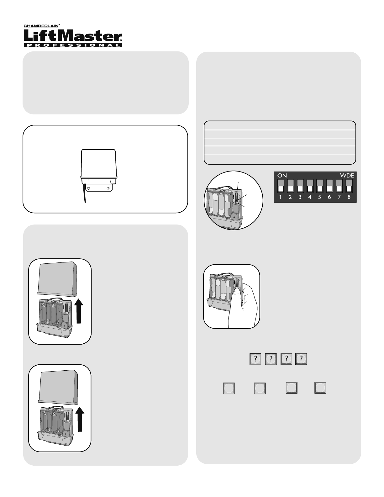
Step 2
Install 4 AA Alkaline batteries
(not provided). (Lithium
batteries recommended for
colder environments.)
1
Model GCU
Gate Control Unit
Step 1
Remove cover.
Assembly
Gate Control Unit (GCU)
Within 20 seconds enter Master PIN Number on
GAPLM:
Followed by GCU Identity as determined in Step 3:
1
2
3
4
OR
OR
OR
The GCU LED will blink 3 times indicating
programming is successful. If error tone is heard or
GCU LED emits 3 double blinks, then programming
has failed.
Repeat for additional GCUs.
“BEEP” “BEEP”
Step 3
NOTE: This step applies only if more than one GCU
is being used.
Up to four GCUs can be used. Each GCU will need a
different Identity. Set the Identity of the GCU by
changing the Dipswitches as shown in the chart
below.
GCU ID Switch #1 Switch #2
1 OFF OFF
2ON OFF
3 OFF ON
4ON ON
Dipswitches
Learn
Button
Step 4
Press the Learn button on the
GCU for one second. The LED
will light for 20 seconds.
LED
Programming to GAPLM
Page 2
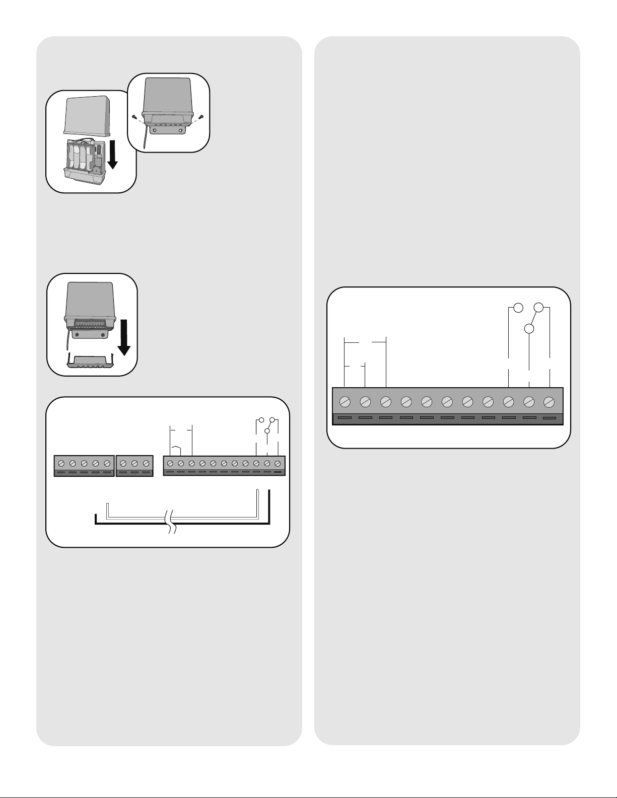
Step 5
Replace GCU cover and mount
near gate operator control box.
Step 6
Remove bottom panel of GCU.
Connect Terminal 10 on GCU
to Common on gate operator
(shown below).
Connect Terminal 9 to Cycle on
gate operator (shown below).
132 4567891011
DC
AC
+
-
COM
N/C
EXIT
SAFETY
EDGE
COMMON
OPEN
GRN
BLK
RED
RECR
N/O
GATE OPERATOR
GCU
Installation
Wiring to Gate Operator
2
Operation
To open a gate enter any valid PIN Number on
GAPLM. For multiple GCU’s, enter the PINNumber
followed by the GCU Identity (1-4).
For a remote control transmitter, press the
corresponding button for 3 seconds (within 75' of
GAPLM).
On an Intercom, press the Remote button while
talking to a visitor. At other times, hold the intercom’s
Remote button for 10 seconds, to activate the
Primary GCU.
NOTE: If the gate operator is not set to automatically
close the gate, any of the above methods can be
repeated to close the gate.
Open/Close Gate
132 4567891011
DC
+
-
N/O
COM
N/C
AC
Gate Terminals
From left to right:
• Terminals 1 and 2: Optional 10-24 Vac power input.
• Terminals 1 and 3: Optional 9-24 Vdc power input.
Ensure that the gate’s DC power supply “Ground” is
wired to terminal 3.
• Terminals 4-8: Not used.
• Terminal 9: Relay Normally Open contact.
• Terminal 10: Relay Common.
• Terminal 11: Relay Normally Closed contact.
Relay connections typically wire to Open Gate input
on gate operator. Up to 120 Vac Low current
contacts. Max 1/2 Amp.
Page 3

3
Gate Operator “ON” Time
Troubleshooting
There is an error tone when the GCU is activated.
The GAPLM or DAILM is not communicating with the
GCU. The GCU may be out of range. If the units work
properly when close together, the GCU may need to
be mounted higher off the ground or on a different
surface. Metal, trees, or masonry cause the most
interference.
If the units do not work when close together, the
GAPLM or DAILM has not been programmed to the
GCU. Double-check the GCU’s Identity (1-4) and
reprogram it.
Memory needs to be cleared.
Hold down the Learn button until the LED blinks a
total of 8 times.
Dipswitches
Learn
Button
LED
“ON” Time Switch #3 Switch #4
1/2 second OFF OFF
1/2 second ON OFF
10 seconds OFF ON
30 seconds ON ON
For most connections the default setting of 1/2
second is best. However, for connection to yard lights,
cameras, etc. the device can be adjusted as to how
long it stays on.
NOTE: For most gate system wiring, dipswitch #4
should be left “OFF”.
Open Gate Configuration
Use this configuration when using the Gate System
as an open-only system, which automatically closes,
based on timer or a magnetic loop.
Enable the Auto-close feature on Gate Operator.
Connect the GCU as shown in Wiring to Operator
section. Refer to product-specific manual for wiring
information. On the Intercom, disable Gate Status
checking.
Page 4

© 2007, The Chamberlain Group Inc.
114A3523 All Rights Reserved
NOTICE: To comply with FCC and or Industry Canada rules (IC), adjustment or modifications of this receiver and/or transmitter are prohibited,
except for changing the code setting or replacing the battery. THERE ARE NO OTHER USER SERVICEABLE PARTS.
Tested to Comply with FCC Standards FOR HOME OR OFFICE USE. Operation is subject to the following two conditions: (1) this device may not
cause harmful interference, and (2) this device must accept any interference received, including interference that may cause undesired operation.
FOR TECHNICAL SUPPORT DIAL OUR TOLL FREE NUMBER:
1-800-528-2806
www.liftmaster.com
 Loading...