

Page 1
RESIDENTIAL GATE OPERATOR
■
■
■
■
■
Models GA400D and GA420D
For Residential Use Only
The Chamberlain Group, Inc.
845 Larch Avenue
Elmhurst, Illinois 60126-1196
www.chamberlain.com
Owner’s Manual
Please read this manual and the enclosed safety materials carefully!
Periodic checks of the operator are required to ensure safe operation.
The model number label is located inside the control box of your operator.
■ Serial #
■ Installation Date
Page 2

TABLE OF CONTENTS
WARNING WARNING
WARNING
WARNING WARNING
WARNING
CAUTION CAUTION
WARNING
WARNING
2-7 INTRODUCTION
2 Safety Symbol and Signal Word Review
3 Operator Specifications
4-5 Safety Installation Information
6 Carton Inventory
6 Hardware Inventory
7 Additional Items for Purchase
7 Tools Needed
8-12 PREPARATION AND OVERVIEW
8 Single Gate Overview
9 Dual Gate Overview
10 Check Your Gate
11 Gate Travel
12 Mounting Options
13-22 INSTALLATION
13-20 Attach Operator to Gate
21-22 Mount the Control Box
23-31 WIRING
23-24 Connect Gate Operator (Gate 1) to Control Box
25-28 Connect Gate Operator (Gate 2) to Control Box
(Model GA420D Only)
29-31 Connect Indoor Transformer to Low Voltage Wire
and Battery
32-35 PROGRAMMING
32-33 Program Limits
34 Force/Timer To Close/Party Mode Controls
35 To Add or Reprogram a Remote Control
35 To Add a Wireless Keyless Entry
35 To Erase All Codes
36-44 OPERATION AND MAINTENANCE
36 Important Safety Information
36 Using Your Gate Operator
37 Manual Release
37 Maintenance
38 Wiring Diagram
39 Diagnostic Chart
40-42 Troubleshooting
43-44 Repair Parts
45 ACCESSORIES
46 WARRANTY
46 REPAIR PARTS AND SERVICE
BACK TEMPLATE FOR POST BRACKET MOUNTING
INTRODUCTION
Safety Symbol and Signal Word Review
This gate operator has been designed and tested to offer safe service provided it is installed, operated, maintained and
tested in strict accordance with the instructions and warnings contained in this manual.
When you see these Safety Symbols and Signal Words on
the following pages, they will alert you to the possibility of
Mechanical
Electrical
Introduction 2
serious injury or death
warnings that accompany them. The hazard may come
from something mechanical or from electric shock. Read
the warnings carefully.
When you see this Signal Word on the following pages, it
will alert you to the possibility of damage to your gate and/
or the gate operator if you do not comply with the
cautionary statements that accompany it. Read them
carefully.
if you do not comply with the
Page 3

Operator Specifications
Main Supply (Motor) 12Vdc Battery run. Operational between 11.5Vdc and 14.5Vdc.
Accessory Power 12V nominal Class II battery voltage source is limited to:
• Solar or AC Cable up to 50' - 500 mA
• AC Cable 50' up to 250' - 250mA
• AC Cable 250' up to 1000' - 100mA
battery life.
Power Consumption 30 Watts max (during battery charging)
Battery Charger Supply 14.5Vac nominal, 30 VA max.
Maximum Gate Length 18 ft. at 350 lbs.
Maximum Gate Weight 850 lbs. at 6 ft.
Travel Time 20 seconds (typical)
Temperature -20ºC to +50ºC, -4ºF to 122ºF Contact Technical Support for applications
Protection Fuse Battery 1 ATC 20A
Protection Fuse Battery 2 ATC 20A
NOTE:
below -20ºC
Increased accessory power drawn from the operator will shorten the
3 Introduction
Page 4
Safety Installation Information
1. READ and FOLLOW all instructions.
2. The gate operator is intended for use with Class I
vehicular swing gates.
Class I denotes a vehicular gate operator (or system)
intended for use in a home of one to four single family
dwellings, or a garage or parking area associated
therewith.
Install the gate operator only when the operator is
appropriate for the construction and the usage class of
the gate.
3. Gate operating system designers, installers and users
must take into account the possible hazards associated
with each individual application. Improperly designed,
installed or maintained systems can create risks for the
user as well as the bystander. Gate system design and
installation must reduce public exposure to potential
hazards. All exposed pinch points must be eliminated
or guarded.
4. A gate operator can create high levels of force during
normal operation. Therefore, safety features must be
incorporated into every installation. Specific safety
features include safety sensors.
5. The gate must be properly installed and work freely in
both directions prior to the installation of the gate
operator.
6. The gate must be installed in a location so that enough
clearance is provided between the gate and adjacent
structures when opening and closing to reduce the risk
of entrapment. Swinging gates shall not open into
public access areas.
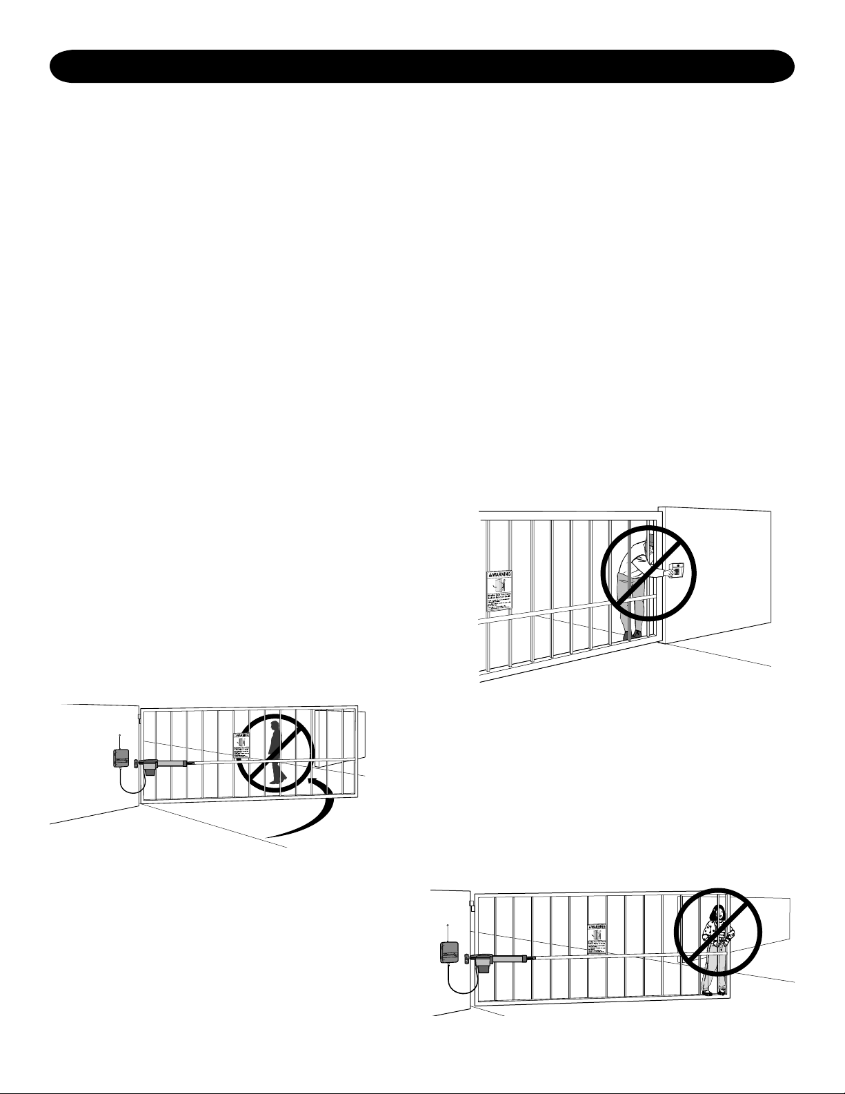
7. The operator is intended for use only on gates used for
vehicles. Pedestrians must be supplied with a separate
access opening. The pedestrian access opening shall
be designed to promote pedestrian usage. The
pedestrian access shall be located such that persons
will not come in contact with the moving vehicular gate.
9. For an installation utilizing non-contact sensors (safety
sensors), see product manual on the placement of
non-contact sensors (safety sensors) for each type of
application.
a. Care shall be exercised to reduce the risk of
nuisance tripping, such as when a vehicle trips the
safety sensor while the gate is still moving.
b. One or more non-contact sensors (safety sensors)
shall be located where the risk of entrapment or
obstruction exists, such as the perimeter reachable
by a moving gate or barrier.
10. For a gate operator utilizing a contact sensor such as
an edge sensor:
a. A hard wired contact sensor shall be located and its
wiring arranged so the communication between the
sensor and the gate operator is not subject to
mechanical damage.
b. One or more contact sensors shall be located on the
inside and outside leading edge of a swing gate.
Additionally, if the bottom edge of a swing gate is
greater than 6" (152 mm) above the ground at any
point in its arc of travel, one or more contact sensors
shall be located on the bottom edge.
11. Never mount any device that operates the gate
operator where the user can reach over, under, around
or through the gate to operate the controls. Controls
are to be placed at least 6' (1.8 m) from any part of the
moving gate:
• A hard wired control device shall be located and its
wiring arranged so that communication between the
control device and the gate operator is not subject to
mechanical damage.
8. Pedestrians should never cross the pathway of a
moving gate. The gate operator is not acceptable for
use on any pedestrian gate. Pedestrians must be
supplied with a separate pedestrian access.
Introduction 4
Page 5
WARNING WARNING
WARNING
12. Controls intended to be used to reset an operator after
Moving Gate Can Cause
Injury or Death
KEEP CLEAR! Gate may move at any
time without prior warning.
Do not let children operate the gate or
play in the gate area.
This entrance is for vehicles only.
Pedestrians must use separate entrance
2 sequential activations of the entrapment protection
device or devices must be located in the line of sight
of the gate, or easily accessible controls shall have a
security feature to prevent unauthorized use. Never
allow anyone to hang on or ride the gate during the
entire travel of the gate.
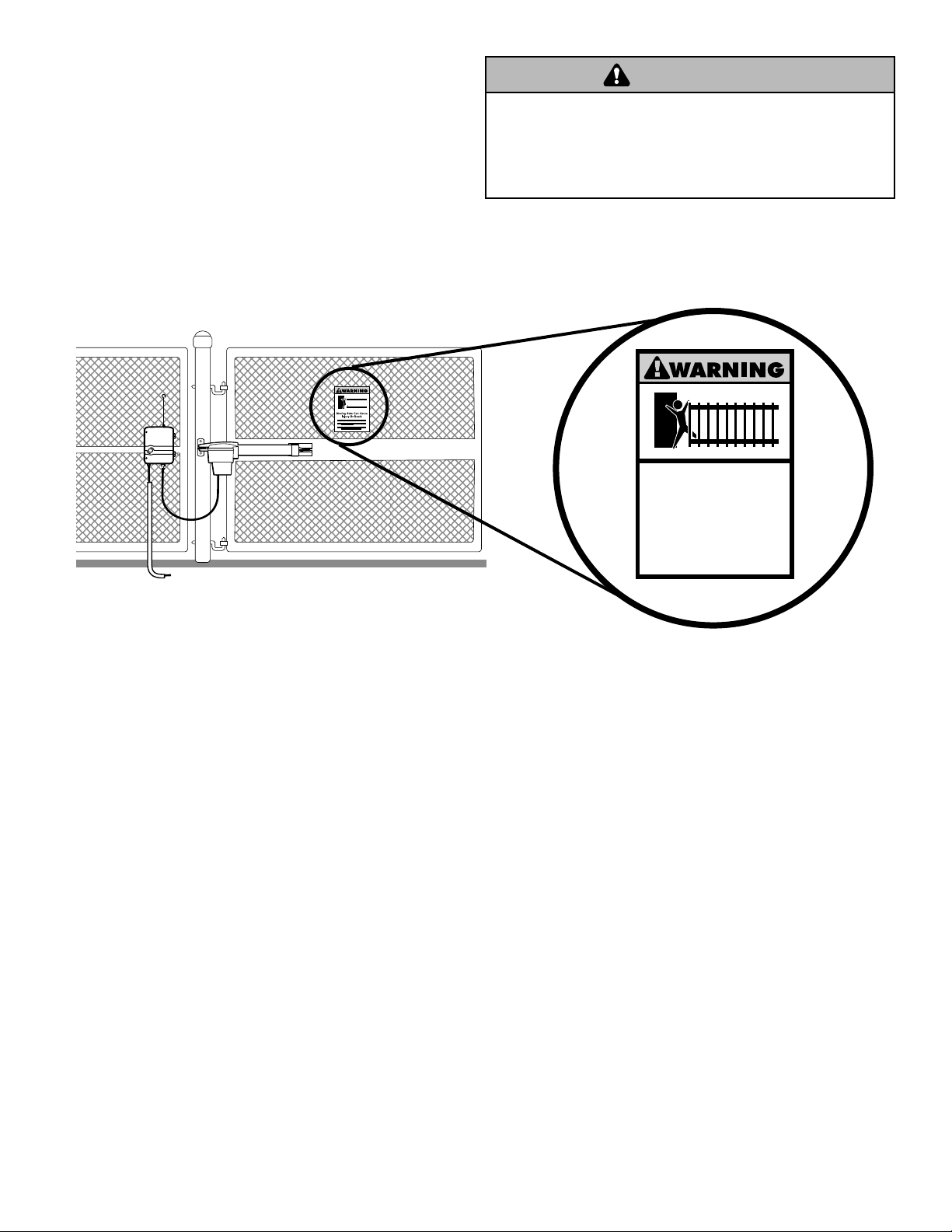
13. Each gate operator is provided with two safety warning
placards. The placards are to be installed on the front
and back of the gate where they are plainly visible.
The placards may be mounted using cable ties
through the four holes provided on each placard.
All warning signs and placards must be installed where
visible in the area of the gate.
To prevent SERIOUS INJURY or DEATH from a moving gate:
• Install warning signs on the front and back of the gate in
PLAIN VIEW.
• Permanently secure each warning sign in a suitable manner
using fastening holes.
14. To AVOID damaging gas, power, or other underground
utility lines, contact underground utility locating
companies BEFORE digging.
15. SAVE INSTRUCTIONS.
5 Introduction
Page 6
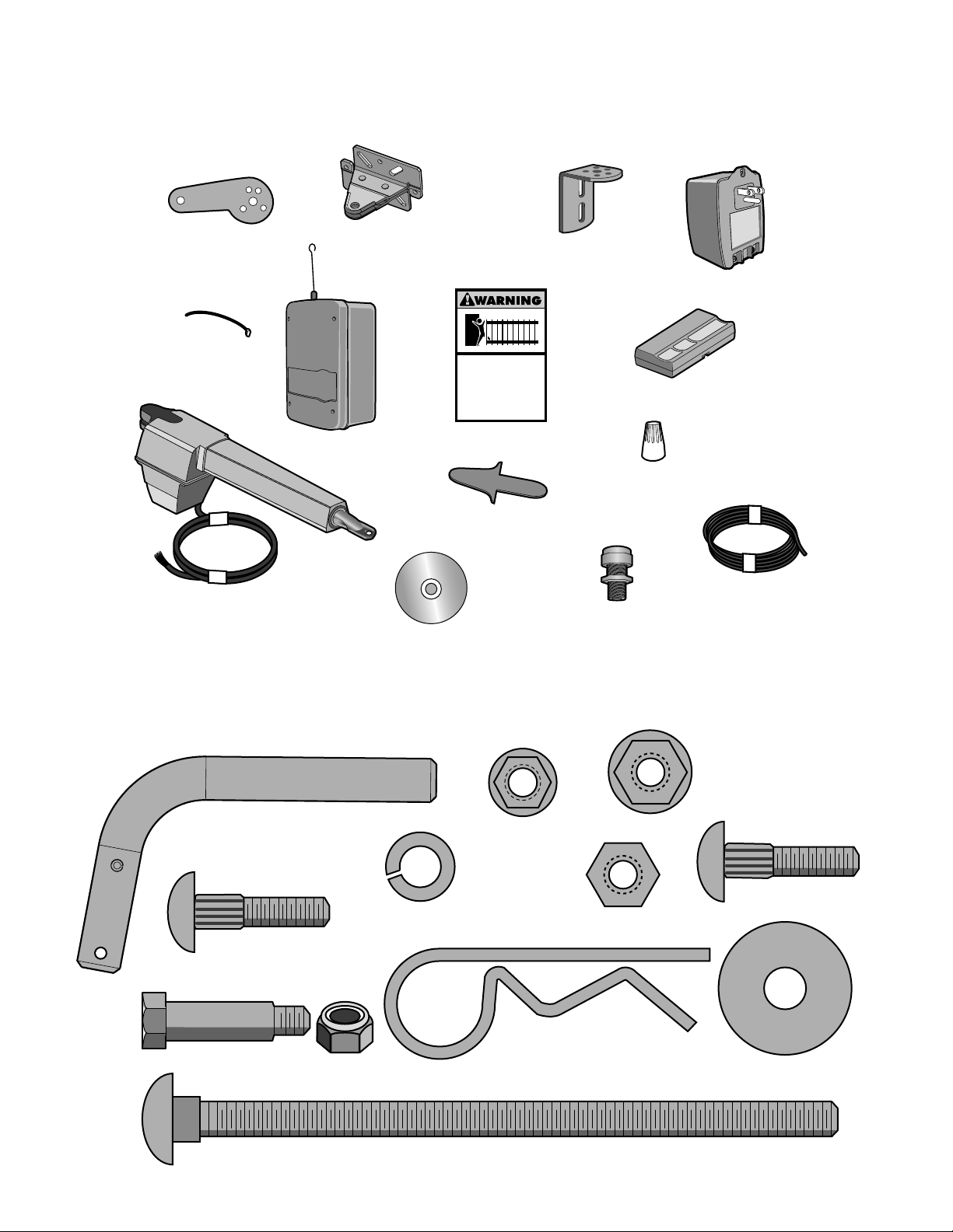
Carton Inventory
This operator comes with the hardware to install on a gate that
pushed open
, accessory kit 919GA is required.
Extension Bracket
Model GA400D (1)
Model GA420D (2)
Cable Ties (4)
Gate Bracket
Model GA400D (1)
Model GA420D (2)
Control Box (1) with:
1 Battery (GA400D)
2 Batteries (GA420D)
Moving Gate Can Cause
Injury or Death
KEEP CLEAR! Gate may move at any
time without prior warning.
Do not let children operate the gate or
play in the gate area.
This entrance is for vehicles only
Pedestrians must use separate entrance
Warning Signs (2)
Arm End Cap
Model GA400D (1)
Model GA420D (2)
pulls-to-open
Post Bracket
Model GA400D (1)
Model GA420D (2)
. If your application requires the gate to be
Plug-In Transformer (1)
SECURITY✚
3-Button Remote Control (1)
Wire Nuts ( 6)
Model GA420D ONLY
®
Hardware Inventory
NOTE:
Hardware quantities shown below are for GA400D. Quantities are doubled for GA420D.
Release Pin (1)
Ribbed Neck Bolt
5/16"-18x1-1/2" (1)
Gate Operator
Model GA400D (1)
Model GA420D (2)
Installation DVD
k Washer 3/8" (2)
Loc
Flange Nut 5/16"-18 (1)
Hex Nut 3/8"-16 (2)
Extension Cable
Model GA420D ONLY
Watertight Connector
Model GA420D ONLY
Flange Nut 3/8"-16 (1)
Ribbed Neck Bolt
3/8"-16x1-1/2" (1)
Hex Head Shoulder
Bolt (1)
Lock Nut With
Nylon Insert (1)
Carriage Bolt 3/8"-16x6" (2)
Introduction 6
Hairpin Clip (1)
Flat Washer 3/8" (2)
Page 7

Additional Items For Purchase
Screwdriver
Adjustable End Wrench
Tape Measure
2
1
Pencil
Carpenter's Level
Clamps
Phillips Head Screwdriver
Deep Well Sockets
and Wrench
1/2", 5/8", 7/16", 9/16"
and 1/4"
Hammer
Drill
Drill Bits
1/2", 3/16", 5/16"
and 5/32"
Wire Cutters (Optional)Wire Strippers (Optional)
Welder (Optional)
The following items are REQUIRED to complete the installation.
All Models:
SAFETY SENSORS
The Safety Sensors, model 916GA, are intended for
installation with the operators covered in this manual.
To order call: 1-866-826-4943 or visit
www.chamberlain-diy.com.
HARDWARE
• 5/16" mounting hardware for gate bracket.
• The following hardware is needed to mount the control box
depending on the mounting surface:
Wood: Four #8 1-1/4" zinc plated wood screws.
Metal: Four #10-32x6" zinc plated machine screws with
nut and lock washers.
Concrete, Brick, etc.: Four 1/4" x 1-3/4" masonry screws.
LOW VOLTAGE WIRE
The low voltage wire is needed to connect the transformer
to the control box. The specific length required depends on
the distance from the indoor outlet to the control box.
Measure carefully, it is not recommended to splice low
voltage wire.
UL approved Class 1 or Class 3 direct burial/underground,
sunlight/UV resistant 16 gauge 2-conductor/stranded low
voltage lighting wire.
The following products are available at most home center
hardware stores and meet these specifications:
• Chamberlain Models 917GA or 918GA
GA420D Only:
JUNCTION BOX
The Junction Box is needed to connect the second arm to
the extension cable (GA420D Installation Only).
• UL Listed outdoor/all-weather junction box with a
minimum of two 3/4" NPT threaded port and appropriate
all-weather cover.
• Conduit fitting to connect 3/4" PVC Schedule 40 conduit
to junction box.
CONDUIT
The conduit is needed to hold the interconnecting cable
between the Junction and Control Box (GA420D
Installation Only).
• 3/4" diameter UL Listed outdoor electrical conduit
AUTOMATIC GATE LOCK AND HARD STOPS (OPTIONAL)
In windy areas to ensure the gate stops at the same place
each time we recommended the purchase of an automatic
gate lock for the closed position and hard stop(s) for the
open position.
Tools Needed
During assembly, installation and adjustment of the operator, instructions will call for tools as illustrated below.
7 Introduction
Page 8
Moving Gate Can Cause
Injury or Death
KEEP C
LEAR!
Gat
e may move at
any
t
ime wi
t
hout prior
warning.
Do n
ot
let childre
n operate the gate or
play in the gate
area.
This e
n
t
rance is for vehicles only
Pedes
trians
must use separat
e entrance
Mov
i
ng Gate Can Cause
Injury or Death
KEEP CL
EAR! Gate ma
y move at any
time wi
thou
t p
rior
warn
in
g.
Do no
t let ch
ildren operate the gate o
r
play i
n
th
e g
ate
area.
This ent
rance is for vehi
cles
on
ly
Pedestr
ians must use sep
arate
entr
an
ce
PREPARATION AND OVERVIEW
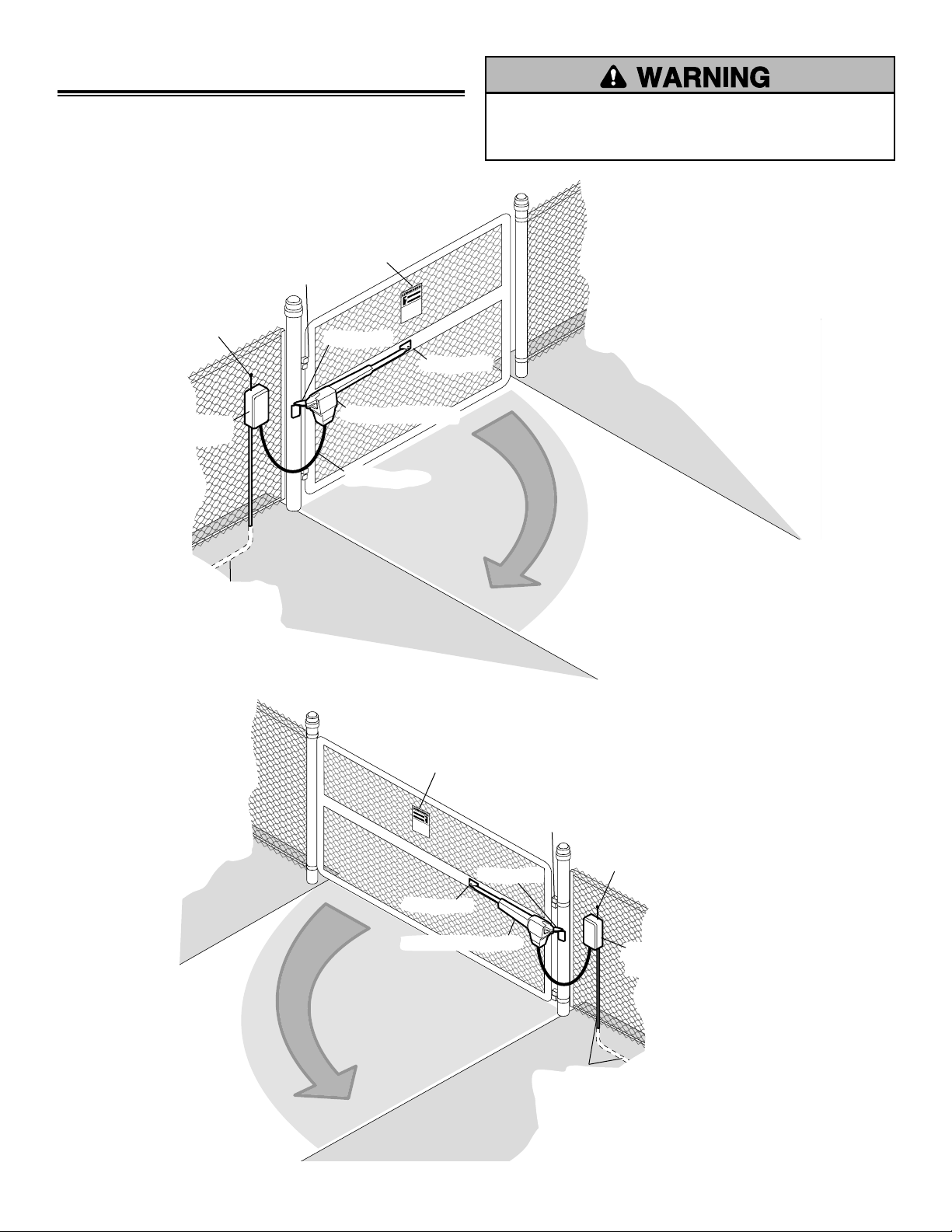
Single Gate Overview
Left-Hand Gate
Outside Property
Antenna
Control Box
with Batteries
To prevent SERIOUS INJURY or DEATH; one or more
non-contact sensors shall be located where the risk of
entrapment or obstruction exists.
Warning Sign
Hinge
Post Bracket
Gate Bracket
Gate Operator (Gate 1)
Operator Cable
Direction of Gate 1
Travel
PVC conduit (not provided) to
protect the power cable and
low voltage wire from lawn
mowers and string trimmers
Right-Hand Gate
Inside Property
Direction of
Gate 1 Travel
Outside Property
Warning Sign
Post Bracket
Gate Bracket
Gate Operator (Gate 1)
Operator Cable
Inside Property
Hinge
NOTE:
One or more non-contact
sensors are located where the risk
of entrapment or obstruction exists
at either the opening or closing
direction. Exercise care to reduce
the risk of nuisance tripping, such
as, when a vehicle trips the sensor
while the gate is still moving.
Antenna
Control Box
with Batteries
Preparation and Overview 8
PVC conduit (not provided) to
protect the power cable and
low voltage wire from lawn
mowers and string trimmers
Page 9
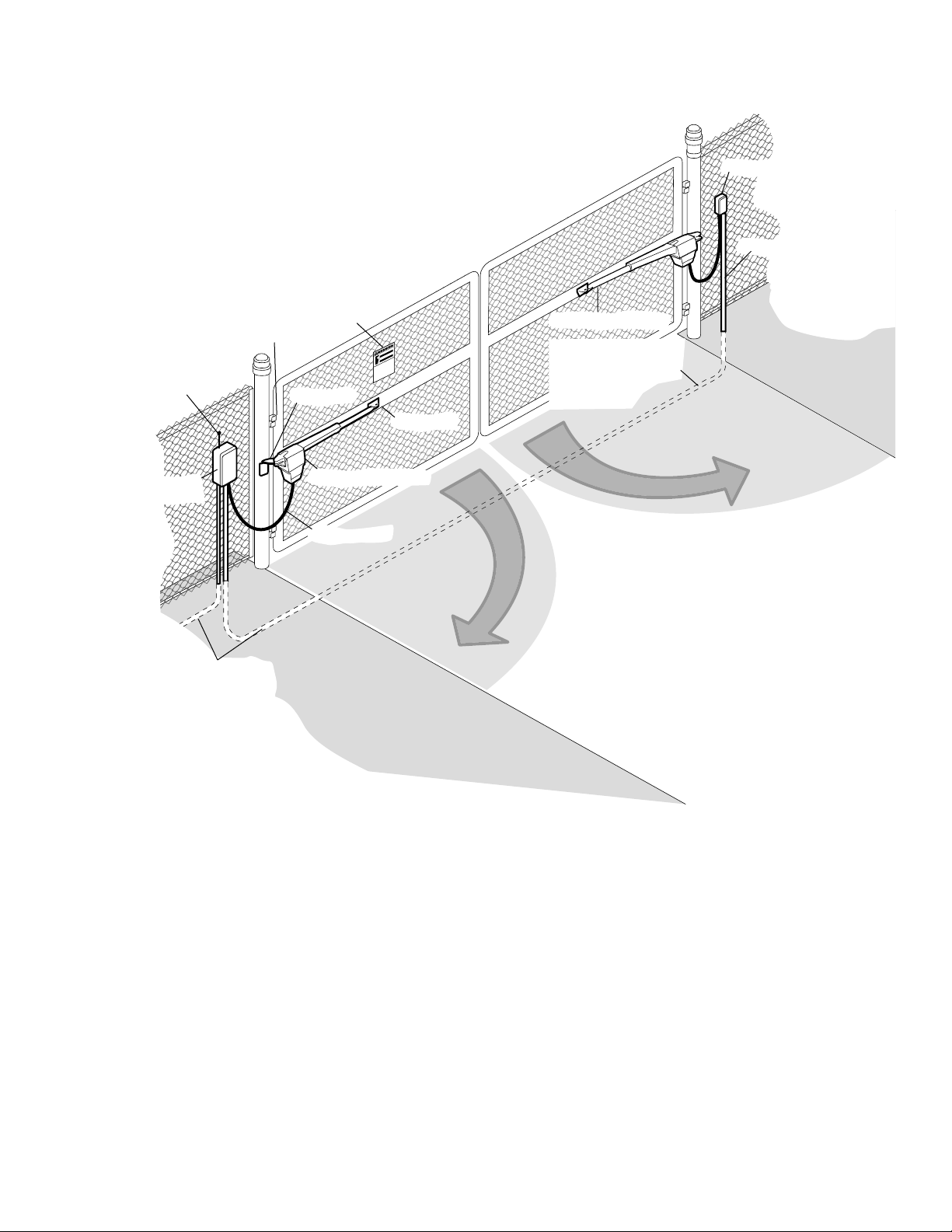
Dual Gate Overview
Outside Property
Inside Property
Moving Gate Can Cause
Injury or Death
KEEP CL
EAR! Gate may move a
t a
ny
t
ime without prior w
ar
ning.
Do not let children operate the g
a
te or
play in the gate area.
This en
t
rance is for vehicles only
Pedest
rians m
ust use s
eparate entrance
Direction of
Gate 1 Travel
Direction of
Gate 2 Travel
Gate Operator (Gate 1)
Operator Cable
Control Box
with Batteries
Antenna
Warning Sign
PVC conduit (not provided) to
protect the power cable and
low voltage wire from lawn
mowers and string trimmers.
Gate Bracket
Post Bracket
Hinge
Gate Operator (Gate 2)
Junction Box
Extension Cable
PVC conduit (not provided)
to protect the power cable
and low voltage wire from
lawn mowers and
string trimmers.
9 Preparation and Overview
Page 10
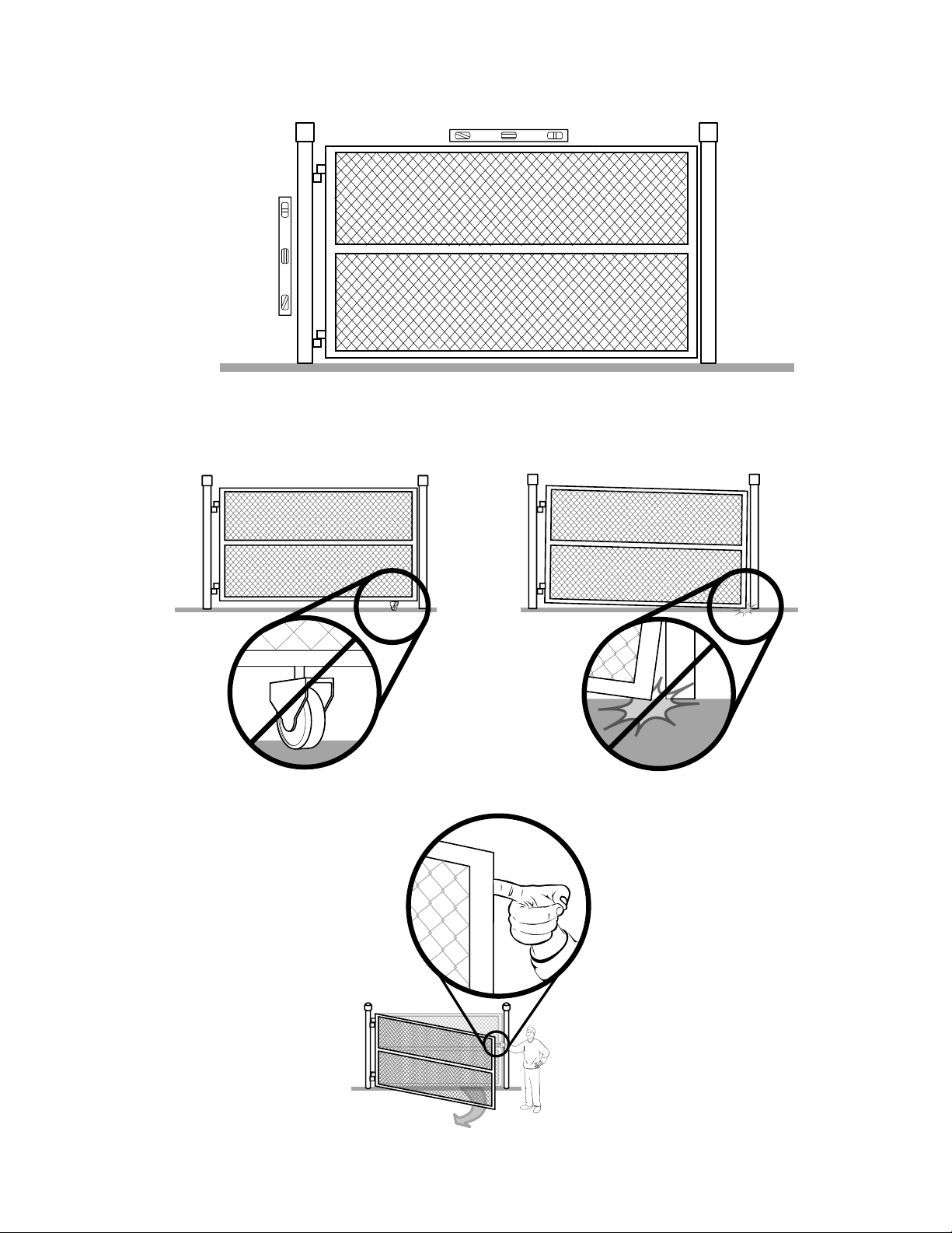
Check Your Gate
Gate MUST be level.
be plumb.
Gate and gate post MUST
Remove ANY/ALL wheels from the bottom of gate.
Gate MUST NOT hit or drag across ground.
Gate MUST swing freely and be supported entirely by its hinges.
Preparation and Overview 10
Page 11
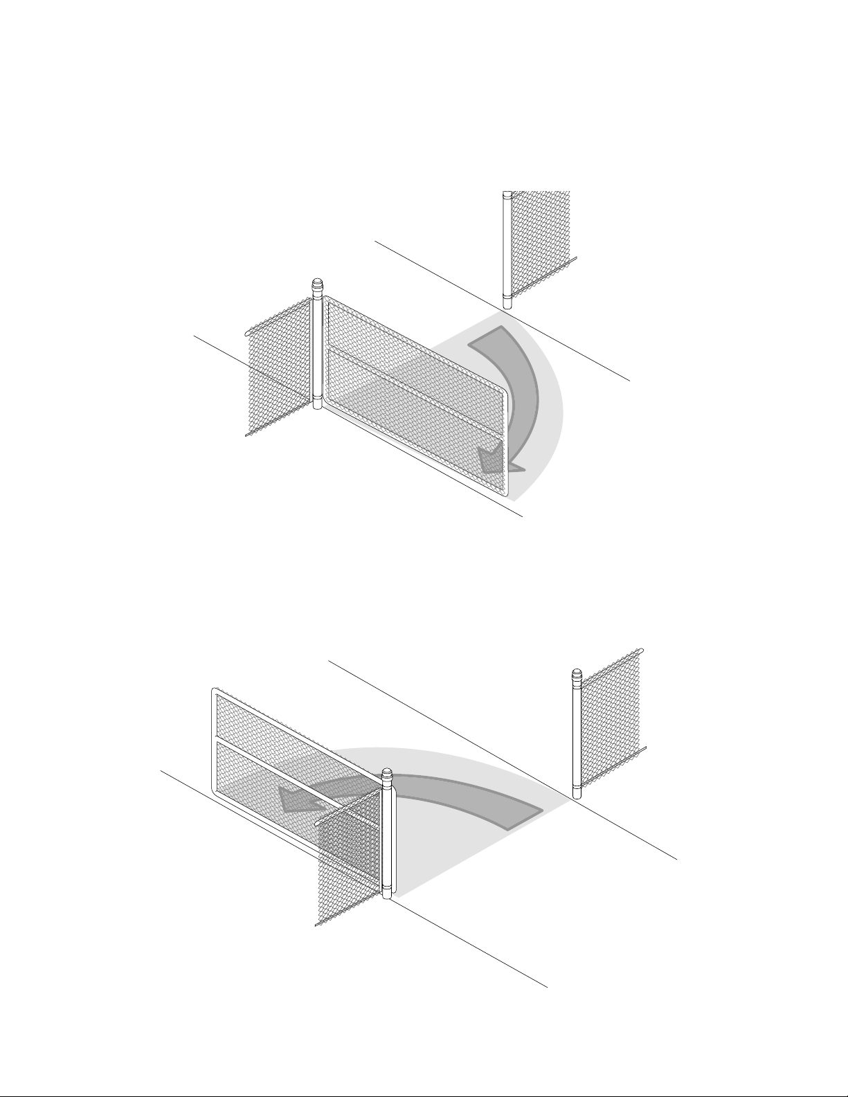
Gate Travel
Determine how your gate is to be opened.
Pull-to-Open
Gate opens into the property. Bracket for Pull-To-Open
installation is provided.
Outside Property
Direction of
Gate Travel
Push-to-Open
Gate opens away from the property and will require the Push-to-Open
kit 919GA. Refer to the Push-To-Open kit for instructions.
Outside Property
Inside Property
Direction of
Gate Travel
Inside Property
11 Preparation and Overview
Page 12
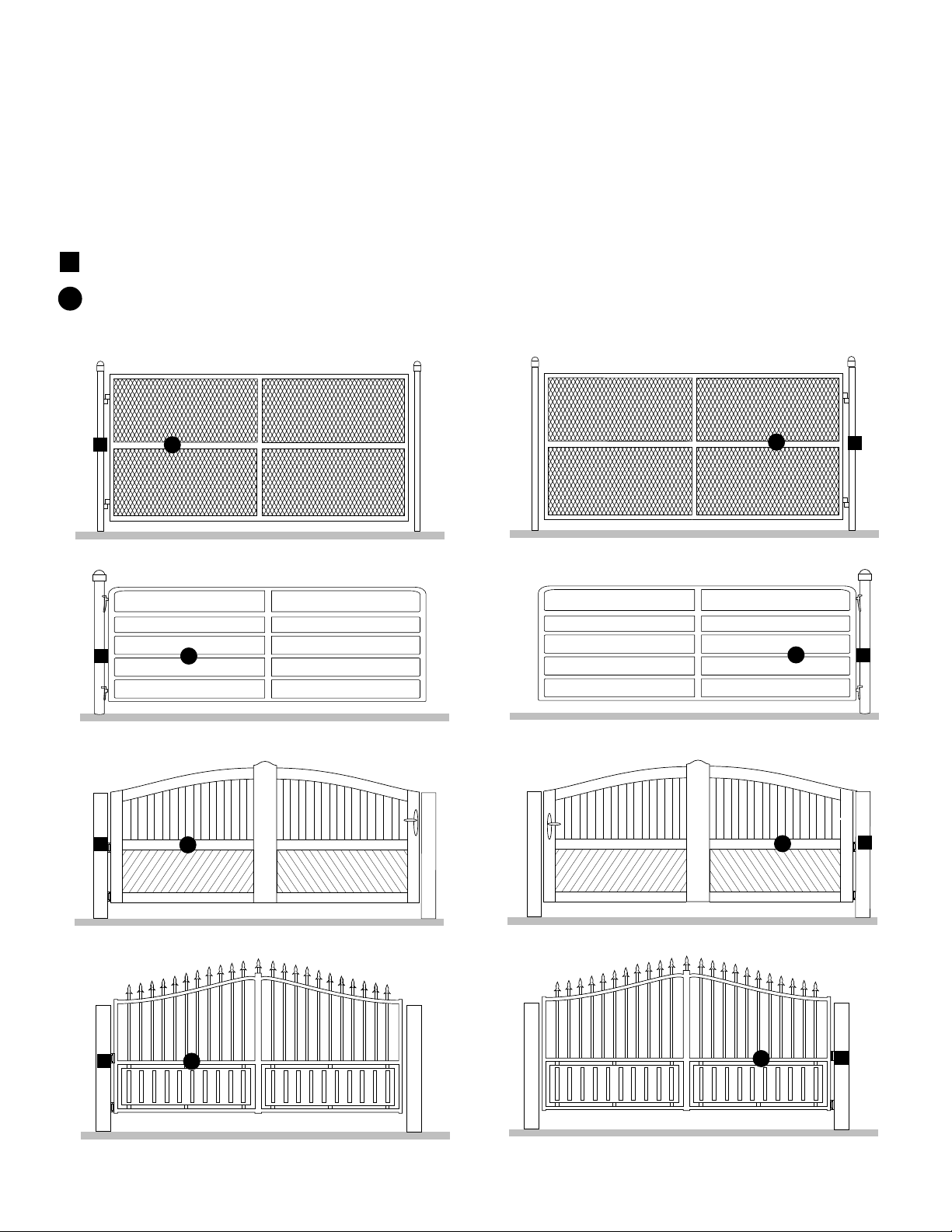
Mounting Options
Mounting locations vary depending on type and style of your gate.
NOTES:
• The top of operator must be mounted at least 10" up from ground. Environmental conditions should be considered at
this time. In windy areas to ensure the gate stops at the same place each time we recommended the purchase of an
automatic gate lock for the closed position and hard stop(s) for the open position.
• Not recommended for plastic or vinyl gates. Refer to gate manufacturer for recommendation and options.
Recommended:
= Gate post bracket mounting locations
= Gate bracket mount locations
Left-Hand Hinge Mounted
Typical Chain Link Gate
Typical Farm/Ranch Gate
Right-Hand Hinge Mounted
Typical Chain Link Gate
Typical Farm/Ranch Gate
Typical Wood Gate
Typical Tubular Metal Gate
Preparation and Overview 12
Typical Wood Gate
Typical Tubular Metal Gate
Page 13
INSTALLATION
Attach Operator to Gate
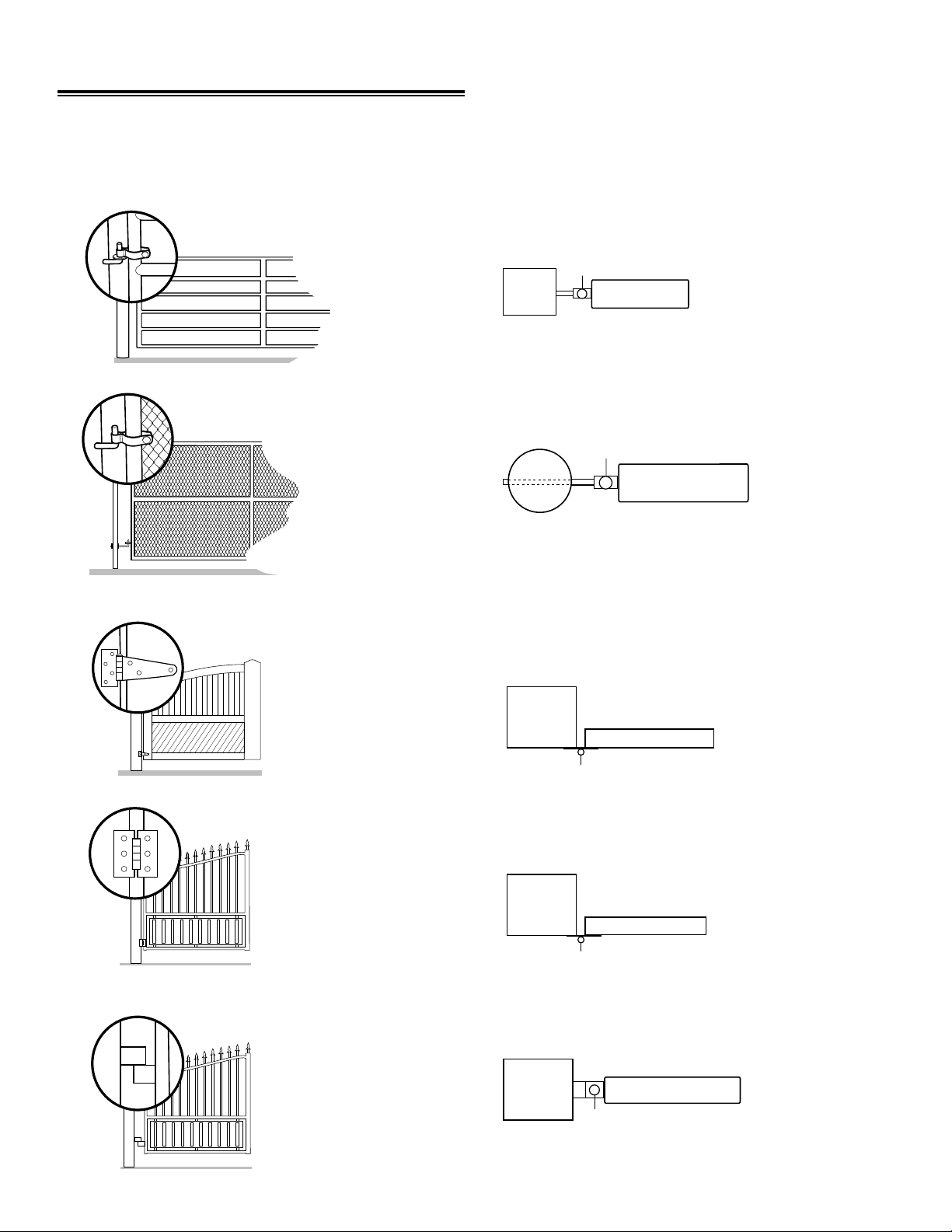
Identify Hinge Type
The illustrations below show common gate hinges. There are many styles of hinges available.
1
J-Bolt Hinge
Top View
Butt Hinge
Gate Post
Gate Post
Gate Post
J-Bolt Hinge Point
J-Bolt Hinge Point
Butt Hinge Point
Gate Post
Butt Hinge Point
Barrel Hinge
Gate Post
Barrel Hinge Point
13 Installation
Page 14
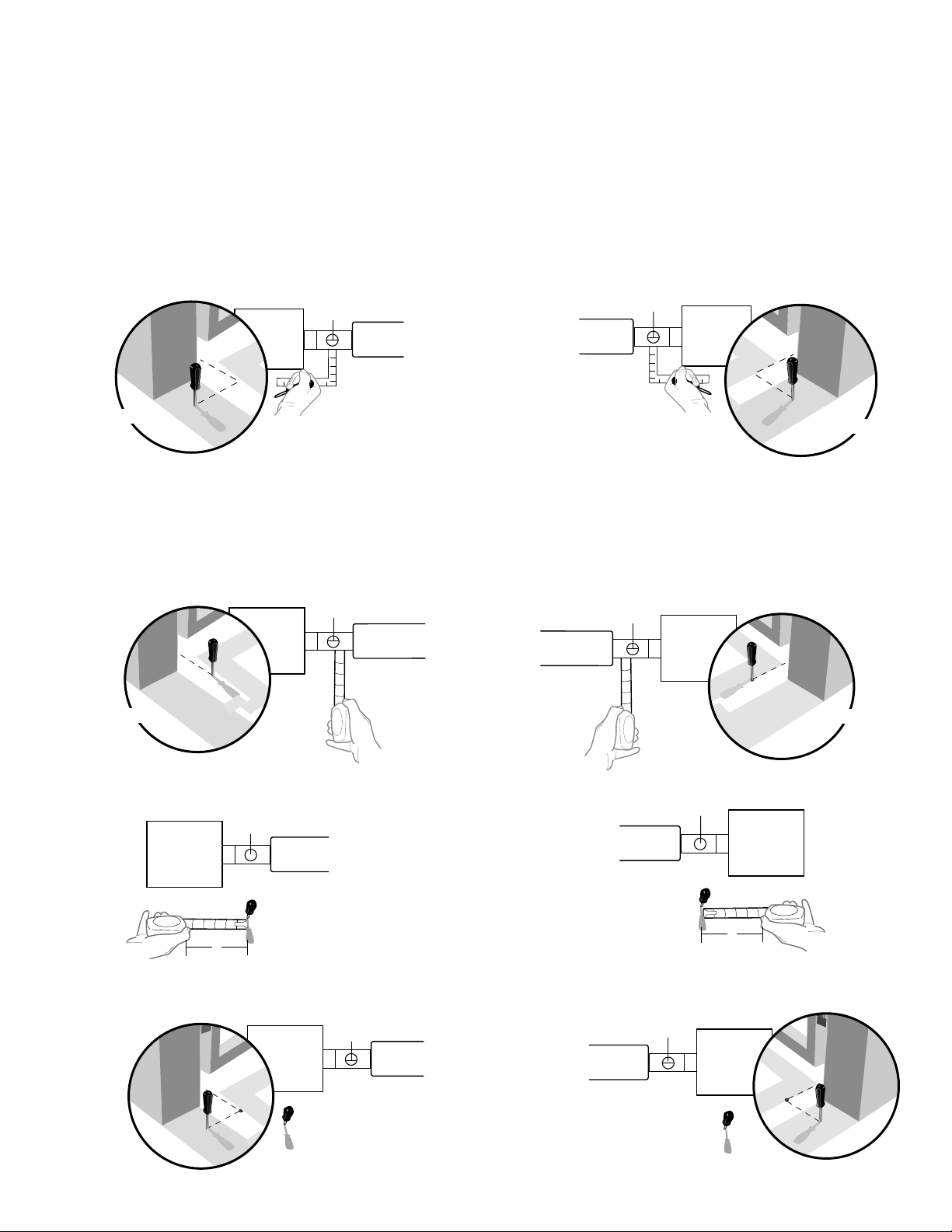
Measuring and Marking for the Gate Bracket
X
X
X
X
X
X
Before proceeding, begin with the gate in the fully closed position. There are two methods described to determine
2
proper location of the post brackets:
• Paper template (to be cut out) located on the back page of this manual.
• Tape measure.
Either method will work depending on preference.
NOTE:
Be sure gate is in
closed
position before proceeding.
Template Method
Place the template (provided on the back page) under the gate hinge point. Use a screwdriver or dowel rod to
temporarily mark the location in front of the gate post.
Left Side Bracket Mounting
Gate Post
Use a screwdriver or dowel rod to
temporarily mark measurement.
Gate Post
Gate Hinge Point
TOP VIEW
Right Side Bracket Mounting
Gate Hinge Point
TOP VIEW
Gate Post
Use a screwdriver or dowel rod to
temporarily mark measurement.
Gate Post
Tape Measure Method
Place the measuring tape under the gate hinge point and measure 5-3/4". Use a screwdriver or dowel rod to
temporarily mark the location of the first measurement.
Left Side Bracket Mounting
Gate Post
Gate Post
Gate Hinge Point
5-3/4"
Right Side Bracket Mounting
Gate Post
Gate Hinge Point
5-3/4"
Gate Post
Measure 5-3/4" from the previous mark.
Gate Post
Gate Hinge Point
5-3/4"
Use the screwdriver or dowel rod to mark the location of the second measurement.
Gate Post
Gate Hinge Point
First Marking
Installation 14
Gate Hinge Point
Gate Hinge Point
First Marking
Gate Post
5-3/4"
Gate Post
Page 15
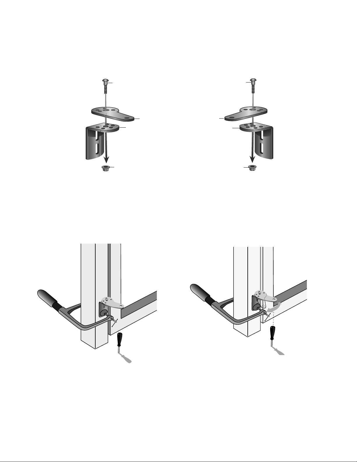
Position the Extension Bracket to Post Bracket
Assemble post bracket by placing the extension bracket on top of post bracket. Insert bolt through brackets
3
and fasten with flange nut. DO NOT TIGHTEN AT THIS TIME.
Left-Hand Gate
3/8 Ribbed Neck Bolt
Extension Bracket Extension Bracket
Post Bracket
Flange Nut
Hold post bracket in desired position. Align extension bracket to a position as CLOSE AS POSSIBLE
above the marker.
3/8 Ribbed Neck Bolt
Post Bracket
Right-Hand Gate
Flange Nut
15 Installation
Page 16

THIS SIDE
TO GATE
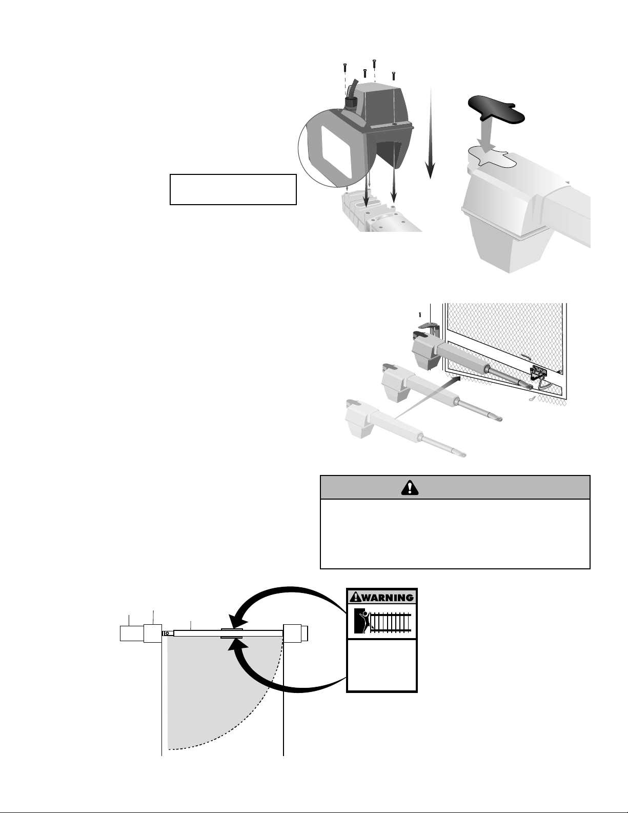
Remove Motor Assembly
Remove screws (4) and remove motor assembly. Set motor aside and place in clean, dry location.
4
NOTE:
Turn operator over to remove screws.
Screws
Motor
Determine Maximum Piston Travel
To ensure proper operation, it is essential to keep the
5
piston from extending and retracting completely.
1
“Slowly extend the piston 1/4"
(.64 cm) from collar and draw
a mark.”
3
2
“Manually extend piston out
as far as possible, push back
1/4" (.64 cm) and then mark.”
Piston
“Always stay within these two marks
to prevent the piston from bottoming
out which could damage the
transmission.”
Installation 16
Page 17

Attach Brackets to Gate Operator
Attach post bracket to gate operator using hex head shoulder bolt and lock nut with nylon insert. Attach gate
6
bracket to operator using release pin and hairpin clip.
Hex Head Shoulder Bolt
Post Bracket
Lock Nut with
Nylon Insert
Release Pin
Hairpin Clip
Position Gate Bracket
Hold the gate operator against the gate. The gate operator (arm) must be level. Clamp bracket to gate. Some
7
installations require a reinforcement be installed on the gate.
Gate Bracket
“After adjustments have been made,
make sure the piston is still within
marked range.”
Piston Range
17 Installation
Page 18

Check Piston Travel
Visually check the clearance. Holding the gate firmly, slowly walk the gate to the fully open position. Check for pinch
8
points at the post mount area.
Gate Travel Path
Gate Travel Path
Allow a minimum of 1/4" between the post bracket and operator. Adjust gate bracket if the piston marks are not
visible in both the open and close direction. Tighten both bolts after final adjustments are made. Bolts should be
fully seated into the brackets.
NOTE:
If gate does not open and close completely, adjust the position of the gate bracket.
Minimum of 1/4"
Installation 18
Page 19

Secure Gate Bracket to Gate
Remove the operator from the brackets. Mark and drill holes in gate or reinforcement (if necessary) according to
9
gate bracket mounting hardware. Secure the gate bracket to gate using hardware (not provided).
NOTE:
The gate bracket can be secured to the gate using a welder (optional).
Lock Down Bolt 1/4"-20
5/16"-18 U-Bolt
Hex Nut
Lock Washer
Flat Washer
10
Gate
Bracket
NOTE:
surfaces, use 5/16"-18 Hex Bolts (4)
through slots instead of U-Bolts.
For mounting on flat
Secure Post Bracket to Gate Post
Mark holes for the post bracket. Remove the clamp and operator. Drill clearance holes for 3/8"-16 bolt in gate post.
NOTE:
Secure the post bracket to gate post using hardware. The gate operator (arm) must be level.
The post bracket can be secured to the gate post using a welder (optional).
Welder Optional
Flat Washers
Hex Nuts
Lock Washers
Carriage Bolts
19 Installation
Page 20
Moving Gate Can Cause
Injury or Death
KEEP CLEAR! Gate may move at any
time without prior warning.
Do not let children operate the gate or
play in the gate area.
This entrance is for vehicles only
Pedestrians must use separate entrance
THIS SIDE
TO GATE
WARNING WARNING
WARNING
11
12
Reattach Motor Assembly
Slide motor assembly onto arm and secure
with screws (4).
to re-install screws. Attach arm cover.
If installing a second gate operator repeat
steps 1-12.
NOTE:
or mirrored on the second operator.
The arm brackets must be reversed
NOTE:
Turn operator over
“THIS SIDE TO GATE”
label MUST face the gate.
Attach Operator to Gate and Bracket
Make sure “THIS SIDE TO GATE” label faces the gate
when reattaching operator to gate. Tighten all bracket
connections.
Arm
Screws
NOTE:
be fully tightened with screw heads
recessed below housing surface.
Motor
Motor housing screws must
Arm Cover
13
14
For Model GA420D Only
Repeat Steps 1-12 for second operator.
Warning Sign Placement
Warning placards MUST be installed on both
sides of the gate and in plain view. Fasten to
gate with cable ties.
Gate Post
Fence
Gate
GATE TRAVEL
PATH
Inside Property
To prevent SERIOUS INJURY or DEATH from a moving gate:
• Install warning signs on the front and back of the gate
in PLAIN VIEW.
• Permanently secure each warning sign in a suitable manner
using fastening holes.
Installation 20
Page 21

Mount the Control Box
RESET
1818
L1L1
K2K2
Z22Z22
F2F2
MOV1MOV1
D1D1
OPEN
SINGLE BUTTON
RESET
STOP
CHGRCHGR
OVLDOVLD
COM
COM
D129D129
Z4Z4
D2D2
C11C11
C13C13
D16D16
F9F9
K1K1
F3F3
K3K3
K4K4
F1F1
Z12Z12
GATE 2GATE 2
GATE 1
GRGR
WHWH
YLYL
BLBL
RDRD
BRBR
GRGR
WHWH
YLYL
BLBL
RDRD
BRBR
F7F7
24V24V
CTRLCTRL
OVLDOVLD
TIMERTIMER
RUNNINGRUNNING
GATE 2GATE 2
SETSET
OPENOPEN
LIMITLIMIT
SETSET
CLOSECLOSE
LIMITLIMIT
LEARNLEARN
LIMITSLIMITS
GATE 1GATE 1
LEARNLEARN
XMITTERXMITTER
LOCK /LOCK /
ONON OFFOFF
C69C69
PWRPWR
AC PWRAC PWR
/SOLAR/SOLAR
R329R329
R27R27
MOV2MOV2
R4R4
C2C2
BIPART DELAYBIPART DELAY
LOCK
Q9Q9
R9R9
Ø
F8F8
C73C73
C72C72
C71C71
C7C7
Ø
R42R42
Ø
R423R423
J24 J23 3J24 J23 3
Ø
A 32VA 32V
3 3
Ø
A 32VA 32V
J21J21
3030
3030
C64C64
R22R22
U2U2
K6K6
JU1JU1
JU1JU1
JU2JU2
DB1DB1
R184R184
ALARM
1818
K2K2
Z22Z22
F2F2
MOV1MOV1
D1D1
D129D129
Z4Z4
D2D2
C11C11
C13C13
D16D16
F9F9
K1K1
F3F3
K3K3
K4K4
F1F1
Z12Z12
GATE 2GATE 2
GRGR
WHWH
YLYL
BLBL
RDRD
BRBR
F7F7
24V24V
GATE 2GATE 2
SETSET
OPENOPEN
LIMITLIMIT
SETSET
CLOSECLOSE
LIMITLIMIT
LEARNLEARN
LIMITSLIMITS
GATE 1GATE 1
C69C69
R329R329
R27R27
MOV2MOV2
R4R4
C2C2
Q9Q9
R9R9
Ø
F8F8
C73C73
C72C72
C71C71
C7C7
Ø
R42R42
Ø
R423R423
J24 J23 3J24 J23 3
Ø
A 32VA 32V
3 3
Ø
A 32VA 32V
J21J21
3030
3030
C64C64
R22R22
U2U2
K6K6
JU1JU1
JU2JU2
DB1DB1
The control box MUST be mounted within 5' of the gate
operator. Mount the control box as high as possible for
best radio reception.
Open the Control Box
Remove screws and open the control box.
1
Remove the Control Board
Disconnect reset button, alarm and coaxial
2
connector. Loosen screws and remove control
board and mounting bracket. Remove batteries and
set aside.
Screws (4)
Alarm
Screws
Screws
Coaxial
Connector
Screws
Control Board
Reset Button
Connections
Screws
Select Mounting Holes
Select holes to be used for mounting and knock out
3
using a screwdriver and hammer.
Knock Outs
Knock Outs
Knock Outs
Knock Outs
Knock Outs
21 Installation
Page 22

Mount the Control Box
1818
L1L1
K2K2
Z22Z22
F2F2
MOV1MOV1
D1D1
OPEN
SINGLE BUTTON
RESET
STOP
CHGRCHGR
OVLDOVLD
COM
COM
D129D129
Z4Z4
D2D2
C11C11
C13C13
D16D16
F9F9
K1K1
F3F3
K3K3
K4K4
F1F1
Z12Z12
GATE 2GATE 2
GATE 1
GRGR
WHWH
YLYL
BLBL
RDRD
BRBR
GRGR
WHWH
YLYL
BLBL
RDRD
BRBR
F7F7
24V24V
CTRLCTRL
OVLDOVLD
TIMERTIMER
RUNNINGRUNNING
GATE 2GATE 2
SETSET
OPENOPEN
LIMITLIMIT
SETSET
CLOSECLOSE
LIMITLIMIT
LEARNLEARN
LIMITSLIMITS
GATE 1GATE 1
LEARNLEARN
XMITTERXMITTER
LOCK /LOCK /
ONON OFFOFF
C69C69
PWRPWR
AC PWRAC PWR
/SOLAR/SOLAR
R329R329
R27R27
MOV2MOV2
R4R4
C2C2
BIPART DELAYBIPART DELAY
LOCK
Q9Q9
R9R9
Ø
F8F8
C73C73
C72C72
C71C71
C7C7
Ø
R42R42
Ø
R423R423
J24 J23 3J24 J23 3
Ø
A 32VA 32V
3 3
Ø
A 32VA 32V
J21J21
3030
3030
C64C64
R22R22
U2U2
K6K6
JU1JU1
JU1JU1
JU2JU2
DB1DB1
R184R184
ALARM
1818
K2K2
Z22Z22
F2F2
MOV1MOV1
D1D1
D129D129
Z4Z4
D2D2
C11C11
C13C13
D16D16
F9F9
K1K1
F3F3
K3K3
K4K4
F1F1
Z12Z12
GATE 2GATE 2
GRGR
WHWH
YLYL
BLBL
RDRD
BRBR
F7F7
24V24V
GATE 2GATE 2
SETSET
OPENOPEN
LIMITLIMIT
SETSET
CLOSECLOSE
LIMITLIMIT
LEARNLEARN
LIMITSLIMITS
GATE 1GATE 1
C69C69
R329R329
R27R27
MOV2MOV2
R4R4
C2C2
Q9Q9
R9R9
Ø
F8F8
C73C73
C72C72
C71C71
C7C7
Ø
R42R42
Ø
R423R423
J24 J23 3J24 J23 3
Ø
A 32VA 32V
3 3
Ø
A 32VA 32V
J21J21
3030
3030
C64C64
R22R22
U2U2
K6K6
JU1JU1
JU2JU2
DB1DB1
Secure the control box to mounting surface (post,
4
wall, column, etc.) using appropriate hardware
(not provided).
Square
Gate Post
Screw
Install the Control Board
Attach antenna. Reinstall batteries, control board,
5
alarm, and reset button. Reconnect coaxial connector.
NOTE:
the control box and not pinched.
Make sure battery leads are on the left side of
Wall
Concrete
Anchor
U-Bolt
(Not Provided)
Antenna
Coaxial
Connector
Screws
Screws
Control Board
Alarm
Reset Button
Screws
Screws
Connections
Installation 22
Page 23

Moving Gate C
an Cause Movi
ng Gate
C
an Cause
Injury or Death I
nj
ury or Death
KEEP CLEAR! K
EE
P C
LEA
R! Gate may move at any G
ate
m
ay move at
any
time witho
ut pri
or warning. ti
m
e wi
tho
ut prior w
arning.
Do n
ot let chi
ld
ren op
erate the gate or D
o n
ot
l
e
t c
hi
l
d
r
e
n ope
rate th
e gate or
play in th
e
gate area. pl
a
y
in
th
e
g
a
t
e
a
rea
.
This entrance is for
vehicles on
ly Th
i
s
e
ntran
c
e
is
fo
r
v
eh
i
c
l
e
s
on
l
y
Pedestrians must use separate en
trance P
e
de
st
ria
ns
mus
t
us
e
s
e
pa
r
a
te
en
tr
a
nc
e
L1
R1
R2
Z1
K5
K6
K2
F3
10A 32V
D1
Ø
P1
Z9
Z8
F2
F6
D4
D2
R9
C64
JMPR1
U4
FORCE
TIMER TO
CLOSE
OFF MAX
FUSE
OPEN
R35
D9
Z3
Z4
U3
D1
D27
F5
C11
C13
C12
D15
C2 R4
R1
Ø
1
R1
ØØ
R9
Ø
Q9
K1
R196
Q22
D8
K3
K4
D21
D22
C4
ACCESSORY
OVLD
D6
JMPR2
MOV1
MOV2
DB1
U2
Z12
24 VAC/
SOLAR
INPUT
GATE 2
ACCESSORY
POWER
MAGLOCK
ALARM
GATE 1
C
C
NC
NO
NO
GRN
WHT
YEL
BLU
RED
BRN
GRN
WHT
YEL
BLU
RED
BRN
F4
10A 32V
F7
24V
TIMER
RUNNING
GATE 2
SET
OPEN
LIMIT
SET
CLOSE
LIMIT
LEARN
LIMITS
DIAGNOSTIC
GATE 1
J4
LEARN
XMITTER
MAGLOCK
ON OFF
Control Box
18 18
R93 R93
D42 D42
K2 K2
D1D1
Ø Ø
Z22 Z22
P1 P1
F2 F2
MOV1 MOV1
D1 D1
Q12 Q12
U4 U4
D129 D129
Z4 Z4
U3 U3
D2 D2
D44 D44
C11 C11
C13 C13
D16 D16
F9 F9
R1R1Ø1 1
R1R1
ØØ ØØ
K1 K1
Q22 Q22
F3 F3
K3 K3
K4 K4
R196 R196
F1 F1
Z12 Z12
GATE 2 GATE 2
GR GR
WH WH
YL YL
BL BL
RD RD
BR BR
F7 F7
24V 24V
GATE 2 GATE 2
SET SET
OPEN OPEN
LIMIT LIMIT
SET SET
CLOSE CLOSE
LIMIT LIMIT
LEARN LEARN
LIMITS LIMITS
GATE 1 GATE 1
C69 C69
J2J2
Ø Ø
D8 D8
D4 D4
R9 R9
R329 R329
R27 R27
MOV2 MOV2
R4 R4
C2 C2
Z1 Z1
R2 R2
K5 K5
F12 F12
Q9 Q9
R9R9
Ø Ø
F8 F8
Q6 Q6
Q1 Q1
C75 C75
C73 C73
C72 C72
C71 C71
C7C7
Ø Ø
C66 C66 C65 C65
C68 C68
C33 C33
F11 F11
R42R42
Ø Ø
R423 R423
J24 J23 3J24 J23 3
Ø
A 32V A 32V
3 3
Ø
A 32V A 32V
J21 J21
30 30
30 30
C64 C64
R22 R22
U2 U2
J18 J18
K6 K6
JU1 JU1
JU2 JU2
DB1 DB1
D36 D36
WARNING
WARNING WARNING
WIRING
To reduce the risk of SEVERE INJURY or DEATH:
• ANY maintenance to the operator or in the area near the
operator MUST not be performed until disconnecting the
electrical power and locking-out the power via the operator
power switch. Upon completion of maintenance the area
MUST be cleared and secured, at that time the unit may be
returned to service.
• Disconnect power at the fuse box BEFORE proceeding.
Operator MUST be properly grounded and connected in
accordance with local electrical codes. NOTE: The operator
should be on a separate fused line with a 15 amp
circuit breaker.
• ALL electrical connections MUST be made by a qualified
individual.
Connect Gate Operator (Gate 1) to Control Box
Watertight Connector Nut
Insert operator cable through watertight connector nut.
1
Watertight Connector Nut
• DO NOT install ANY wiring or attempt to run the operator
without consulting the wiring diagram. We recommend that
you install an optional reversing edge BEFORE proceeding
with the control station installation.
• ALL power wiring should be on a dedicated circuit and well
protected. The location of the power disconnect should be
visible and clearly labeled.
• ALL power and control wiring MUST be run in separate
conduit.
• BEFORE installing power wiring or control stations be sure to
follow ALL specifications and warnings described below.
Failure to do so may result in SEVERE INJURY to persons
and/or damage to operator.
Operator
Cable
Insert Operator Cable
Insert watertight connector into the bottom of the control box and tighten with nut. Insert operator
2
cable through watertight connector mounted in the bottom of the control box.
Nut
Watertight
Connector
Operator
Cable
Watertight
Connector
Watertight
Connector Nut
23 Wiring
Page 24

Connect Operator to Control Board
Moving Gate C
an Cause
Injury or Death
KEEP CLEAR! Gate may move at any
time witho
ut pri
or warning.
Do n
ot let chi
ld
ren op
erate the gate or
play in th
e
gate area.
This entrance is for
vehicles on
ly
Pedestrians must use separate en
trance
Z22
R91
CLOSE
EDGE
R94
R92
R93
L1
R1
R2
Z1
K5
K6
K2
F3
10A 32V
D1
Ø
OPEN EDGE/
PHO T O
OPEN
PHO T O
CLOSE
PHO T O
R227
R2
Ø
7
Z2
Ø
R223
P1
Z9
Z8
F2
F6
D4
D2
R9
C64
JMPR1
R224
U4
CONTROL
INPUTS
FORCE
TIMER TO
CLOSE
OFF MAX
OPEN
SINGLE BUTTON
RESET
STOP
SHADOW
INTERRUPT
CHGR
OVLD
COM
COM
COM
FUSE
OPEN
LOOP
INPUTS
POWER
BATT 1 BATT 2
F1 20A 32V
R35
D9
Z3
Z4
U3
D1
D27
F5
C11
C13
C12
D15
C2 R4
R1
Ø
1
R1
ØØ
R9
Ø
Q9
K1
R196
Q22
D8
K3
K4
D21
D22
C4
ACCESSORY
OVLD
D6
JMPR2
MOV1
MOV2
DB1
U2
Z12
24 VAC/
SOLAR
INPUT
GATE 2
ACCESSORY
POWER
MAGLOCK
ALARM
GATE 1
C
C
NC
NO
NO
GRN
WHT
YEL
BLU
RED
BRN
GRN
WHT
YEL
BLU
RED
BRN
F4
10A 32V
F7
24V
COM
OVLD
TIMER
RUNNING
GATE 2
SET
OPEN
LIMIT
SET
CLOSE
LIMIT
LEARN
LIMITS
DIAGNOSTIC
GATE 1
J4
LEARN
XMITTER
MAGLOCK
ON OFF
F2
F6
U4
MAX
FUSE
OPEN
C13
C4
Z1
10A 32V
D1Ø
R9
Ø
Z12
ACCESSORY
POWER
GATE 1
NC
GRN
WHT
YEL
BLU
RED
BRN
Extend operator cable and wires to GATE 1 connector and
3
connect as shown. Tighten watertight connector nut.
Brown
Green
White
Yellow
Blue
Red
Watertight Connector Nut
Terminal blocks
can be removed
to simplify wiring.
CONTROL BOX
Operator Cable
If installing one operator, proceed to page 29.
If installing two operators, continue to the next page.
Wiring 24
Operator Cable
Page 25

Control Box
1818
R93R93
D42D42
K2K2
D1D1
Ø
Z22Z22
P1P1
F2F2
MOV1MOV1
D1D1
Q12Q12
U4U4
D129D129
Z4Z4
U3U3
D2D2
D44D44
C11C11
C13C13
D16D16
F9F9
R1R1Ø1
R1R1
ØØØØ
K1K1
Q22Q22
F3F3
K3K3
K4K4
R196R196
F1F1
Z12Z12
GATE 2GATE 2
GRGR
WHWH
YLYL
BLBL
RDRD
BRBR
F7F7
24V24V
GATE 2GATE 2
SETSET
OPENOPEN
LIMITLIMIT
SETSET
CLOSECLOSE
LIMITLIMIT
LEARNLEARN
LIMITSLIMITS
GATE 1GATE 1
C69C69
J2J2
Ø
D8D8
D4D4
R9R9
R329R329
R27R27
MOV2MOV2
R4R4
C2C2
Z1Z1
R2R2
K5K5
F12F12
Q9Q9
R9R9
Ø
F8F8
Q6Q6
Q1Q1
C75C75
C73C73
C72C72
C71C71
C7C7
Ø
C66C66 C65C65
C68C68
C33C33
F11F11
R42R42
Ø
R423R423
J24 J23 3J24 J23 3
Ø
A 32VA 32V
3 3
Ø
A 32VA 32V
J21J21
3030
3030
C64C64
R22R22
U2U2
J18J18
K6K6
JU1JU1
JU2JU2
DB1DB1
D36D36
C71
C7Ø
ON
OFF
LOCK/
BIPART DELAY
18
R93
D42
K2
D1
Ø
Z22
P1
F2
MOV1
D1
Q12
U4
D129
Z4
U3
D2
D44
C11
C13
D16
F9
R1Ø1
R1
ØØ
K1
Q22
F3
K3
K4
R196
F1
Z12
GATE 2
GR
WH
YL
BL
RD
BR
F7
24V
GATE 2
SET
OPEN
LIMIT
SET
CLOSE
LIMIT
LEARN
LIMITS
GATE 1
C69
J2
Ø
D8
D4
R9
R329
R27
MOV2
R4
C2
Z1
R2
K5
F12
Q9
R9
Ø
F8
Q6
Q1
C75
C73
C72
C71
C7
Ø
C66 C65
C68
C33
F11
R42
Ø
R423
J24 J23 3
Ø
A 32V
3
Ø
A 32V
J21
30
30
C64
R22
U2
J18
K6
JU1
JU2
DB1
D36
Connect Gate Operator (Gate 2) to Control Box (Model GA420D Only)
Occasionally in dual gate installations, one gate would need to open first and close second. This would happen if there
was an ornamental overhang on one gate or if using a solenoid lock, for example. This gate is called the Primary gate
and needs to be connected to Gate 1 connections on the control board. Thus, it is preferred that the control box be
installed on the same side as this gate. If there is no appropriate location on that side for the control box, then mount the
control box on the opposite side, but connect the operator closest to the control box to the Gate 2 connector and the
operator on the opposite side to the Gate 1 connector.
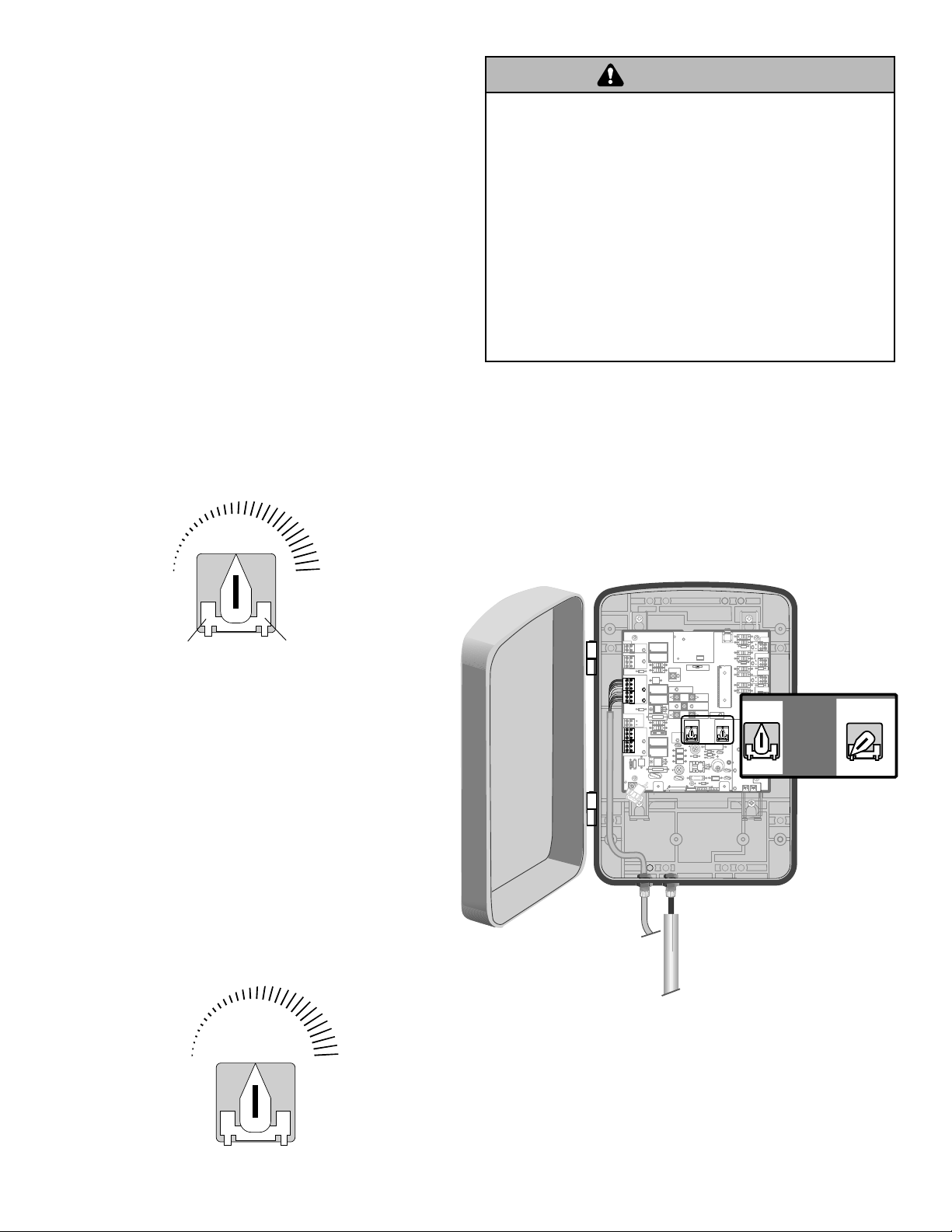
Set the Lock/Bipart Delay
The LOCK/BIPART DELAY switch on the control board
needs to be set to the ON position.
The following illustration shows a dual gate configuration
with a decorative overlapping piece on the outside of the
gate.
Outside Property
Primary Gate - Connect to Gate 1 Connector on Control
Board.
Primary Gate
Outside Property
If a solenoid lock is being used on a gate, the gate with
the lock attached to it would be the primary gate.
25 Wiring
Page 26

Connect second Operator to Control
WARNING
CAUTION CAUTION
WARNING
WARNING
L1
R1
R2
Z1
K5
K6
K2
F3
10A 32V
D1
Ø
P1
F2
F6
D4
D2
R9
C64
JMPR1
U4
FORCE
TIMER TO
CLOSE
OFF MAX
R35
D9
Z3
Z4
U3
D1
D27
F5
C11
C13
C12
D15
C2 R4
R1
Ø
1
R1
ØØ
R9
Ø
Q9
K1
R196
Q22
D8
K3
K4
D21
D22
C4
ACCESSORY
OVLD
D6
JMPR2
MOV1
MOV2
DB1
U2
Z12
24 VAC/
SOLAR
INPUT
GATE 2
ACCESSORY
POWER
MAGLOCK
ALARM
GATE 1
C
C
NC
NO
NO
GRN
WHT
YEL
BLU
RED
BRN
GRN
WHT
YEL
BLU
RED
BRN
F4
10A 32V
F7
24V
TIMER
RUNNING
GATE 2
SET
OPEN
LIMIT
SET
CLOSE
LIMIT
LEARN
LIMITS
DIAGNOSTIC
GATE 1
J4
LEARN
XMITTER
MAGLOCK
ON OFF
Z22
R91
CLOSE
EDGE
R94
R92
R93
L1
R1
R2
Z1
K5
K6
K2
F3
10A 32V
D1
Ø
OPEN EDGE/
PHO T O
OPEN
PHO T O
CLOSE
PHO T O
R227
R2
Ø
7
Z2
Ø
R223
P1
Z9
Z8
F2
F6
D4
D2
R9
C64
JMPR1
R224
U4
CONTROL
INPUTS
FORCE
TIMER TO
CLOSE
OFF MAX
OPEN
SINGLE BUTTON
RESET
STOP
SHADOW
INTERRUPT
CHGR
OVLD
COM
COM
COM
FUSE
OPEN
LOOP
INPUTS
POWER
BATT 1 BATT 2
F1 20A 32V
R35
D9
Z3
Z4
U3
D1
D27
F5
C11
C13
C12
D15
C2 R4
R1
Ø
1
R1
ØØ
R9
Ø
Q9
K1
R196
Q22
D8
K3
K4
D21
D22
C4
ACCESSORY
OVLD
D6
JMPR2
MOV1
MOV2
DB1
U2
Z12
24 VAC/
SOLAR
INPUT
GATE 2
ACCESSORY
POWER
MAGLOCK
ALARM
GATE 1
C
C
NC
NO
NO
GRN
WHT
YEL
BLU
RED
BRN
GRN
WHT
YEL
BLU
RED
BRN
F4
10A 32V
F7
24V
COM
OVLD
TIMER
RUNNING
GATE 2
SET
OPEN
LIMIT
SET
CLOSE
LIMIT
LEARN
LIMITS
DIAGNOSTIC
GATE 1
J4
LEARN
XMITTER
MAGLOCK
ON OFF
D15
C2 R4
R9
Ø
R196
24 VAC/
SOLAR
GATE 2
ACCESSORY
POWER
GRN
WHT
YEL
BLU
RED
BRN
10A 32V
24V
Moving Gate Can Cause
In
jury or Death
KEEP CLEAR!
G
ate may move at any
time with
out pr
i
o
r warnin
g.
Do not let
children o
perat
e the gat
e or
play in the gate area.
This entr
an
ce is f
or vehicles o
nly
Pedestrians must use separate entrance
1
Board (Model Ga420D Only)
• Before digging, contact local underground utility
locating companies.
• Trench across driveway to bury the extension
cable.
• Use PVC conduit to prevent damage to cables.
• Insert extension cable through watertight
connector nut and through an available watertight
connector mounted in the control box.
• Extend cable and wires to GATE 2 connector and
connect as shown.
• Secure extension cable to control box using
watertight connector nut.
To AVOID damaging gas, power or other underground utility
lines, contact underground utility locating companies BEFORE
digging.
Brown
Green
White
Yellow
Blue
Red
Control Box
Terminal blocks
Extension Cable
Operator
Cable
can be removed
to simplify wiring.
PVC Conduit
Junction Box
Extension Cable
PVC conduit at
least 18" below
Gate Operator (Gate 2)
ground level
(grade)
Gate Operator (Gate 1)
PVC conduit (not provided) to protect the
power cable and low voltage wire from lawn
mowers and string trimmers.
Wiring 26
Page 27

Junction Box
M
ovin
g
G
at
e
C
an
C
au
se
In
j
u
ry
or
D
eath
KEE
P
C
L
EAR! G
a
t
e
ma
y
m
o
v
e
at
a
ny
tim
e
w
i
t
h
o
u
t
p
r
io
r
w
a
rn
in
g
.
D
o
n
o
t
le
t
ch
il
d
r
en
o
p
e
r
at
e
th
e
g
a
t
e
o
r
pla
y
in
th
e
g
a
t
e
a
rea
.
Th
i
s
e
n
t
r
an
c
e
is
f
or
ve
hi
cl
e
s o
n
l
y
P
e
d
e
s
tr
ian
s
m
u
s
t u
s
e
s
e
p
a
r
a
te e
n
t
r
a
n
c
e
2
The following items are required to complete the junction box (not provided) installation:
• 4 x 4 Junction Box with 3/4 NPT threaded port holes
• Screws
• PVC Conduit
Open the junction box by removing screws (4) and set aside.
Mount the junction box within 5' of second operator.
Screws (4)
Junction Box Cover
Junction Box
(not provided)
Control Box
Gate Operator (Gate 1)
Within 5' PVC conduit (not provided) to
protect the power cable and low voltage wire
from lawn mowers and string trimmers.
Within 5'
Junction Box
Extension Cable
Gate Operator (Gate 2)
27 Wiring
Page 28

Connect Watertight Connectors
3
Route operator cable and extension cable through watertight connector nut and watertight connector. Insert cables
and watertight connectors into the holes in the bottom of the junction box (not provided). Feed extension cable
through PVC conduit and secure with connector nut.
Junction Box (not provided)
Operator
Cable
Watertight Connector
Watertight Connector
Extension Cable
Watertight Connector Nut
Watertight Connector Nut
PVC Conduit
Connect Wires in Junction Box
4
Remove terminals from operator cable. Strip wires and twist like colored wires together with wire nuts.
Wire Nut
Brown
Brown
Green
Operator Cable
Green
White
Yellow
Blue
Red
White
Blue
Red
Extension Cable
Yellow
Secure Junction Box
5
Put wires inside of junction box. Secure operator and
extension cables with watertight nut. Reinstall cover.
Junction Box
Operator Cable
Extension Cable
Watertight Connector Nut
Wiring 28
Watertight Connector Nut
PVC Conduit
Junction Box
(not provided)
Screws (4)
Page 29

Moving Gate Can Cause
I
njury or Death
KE
E
P
CL
E
AR
!
G
a
t
e
m
a
y
m
o
v
e
a
t
a
n
y
t
im
e
w
i
t
h
o
u
t
p
r
i
o
r
wa
rn
i
n
g
.
D
o
n
o
t
l
e
t
c
h
il
d
r
e
n
o
p
e
r
a
t
e
th
e
g
a
t
e
o
r
pl
a
y
i
n
t
h
e
g
a
t
e
a
r
e
a
.
Th
i
s
e
n
t
r
a
n
c
e
i
s
f
o
r
v
e
h
i
c
l
e
s
o
n
l
y
Pe
d
e
s
t
r
ia
n
s
m
u
s
t
u
se
s
e
p
a
r
a
t
e
e
n
t
ra
n
c
e
WARNING
CAUTION CAUTION
WARNING
WARNING
Connect Indoor Transformer to Low Voltage Wire and Battery
• Before digging, contact local underground utility
locating companies.
• Trench and run low voltage (16 AWG) wire for
transformer from control box to an outlet inside the
home or building.
• Run wires through PVC conduit to protect the power
wires from lawn mowers, string trimmers, etc.
NOTE:
conditions must be reviewed for suitability of wire
installation.
Calculated using NEC guidelines. Local codes and
To AVOID damaging gas, power or other underground utility lines,
contact underground utility locating companies BEFORE digging.
Insert transformer wires (power wires)
through watertight connector nut.
Indoor Outlet
Watertight
Connector Nut
Power Wires
Operator Cable
Indoor Outlet
Power
Wires
29 Wiring
Page 30
1818
R93
L1L1
K2K2
Z22Z22
P1P1
F2F2
MOV1MOV1
D1D1
Q12Q12
U4U4
OFFOFF MAXMAX
OPEN
SINGLE BUTTON
RESET
STOP
CHGR
OVLD
CTRL PWR
COM
D129D129
Z4Z4
U3U3
D2D2
D44D44
C11C11
C13C13
C12C12
D16D16
F9F9
R1R1Ø1
R1R1
ØØØØ
Q22Q22
F3F3
K3K3
K4K4
R196R196
F1F1
GATE 2GATE 2
GATE 1GATE 1
GRGR
WHWH
YLYL
BLBL
RDRD
BRBR
F7F7
24V24V
CTRL
OVLD
TIMERTIMER
RUNNINGRUNNING
GATE 2GATE 2
SETSET
OPEN
SETSET
CLOSECLOSE
LIMITLIMIT
LEARNLEARN
LIMITSLIMITS
GATE 1GATE 1
LOCK /LOCK /
ONON OFFOFF
C69C69
OFFOFF MAXMAX
J2J2
Ø
PWR
AC PWR
/SOLAR
D8D8
D4D4
R9R9
R329R329
R27R27
R4
C2C2
BIPART DELAYBIPART DELAY
LOCKLOCK
R9R9
Ø
Q6Q6
J19J19
R182R182
C1
Ø1Ø1
C75C75
C73C73
C72C72
C71C71
C7C7
Ø
C66C66 C65C65
C68C68
C33C33
F11F11
R186R186
R42R42
Ø
R423R423
J24 J23 3J24 J23 3
Ø
A 32VA 32V
3 3
Ø
A 32VA 32V
J21J21
3030
3030
C64C64
R22R22
U2U2
J18J18
K6K6
JU1JU1
JU1JU1
JU2JU2
DB1DB1
R184R184
MOV1MOV1
CHGR
OVLD
AC PWR
/SOLAR
MOV2
R4
C2
LE BUTTON
K2
K1K1
SET
OPEN
LIMIT
C73
C72
C71
DIAGNOSTIC
OPEN
SINGLE BUTTON
RESET
STOP
CTRL PWR
CTRL
OVLD
PWR
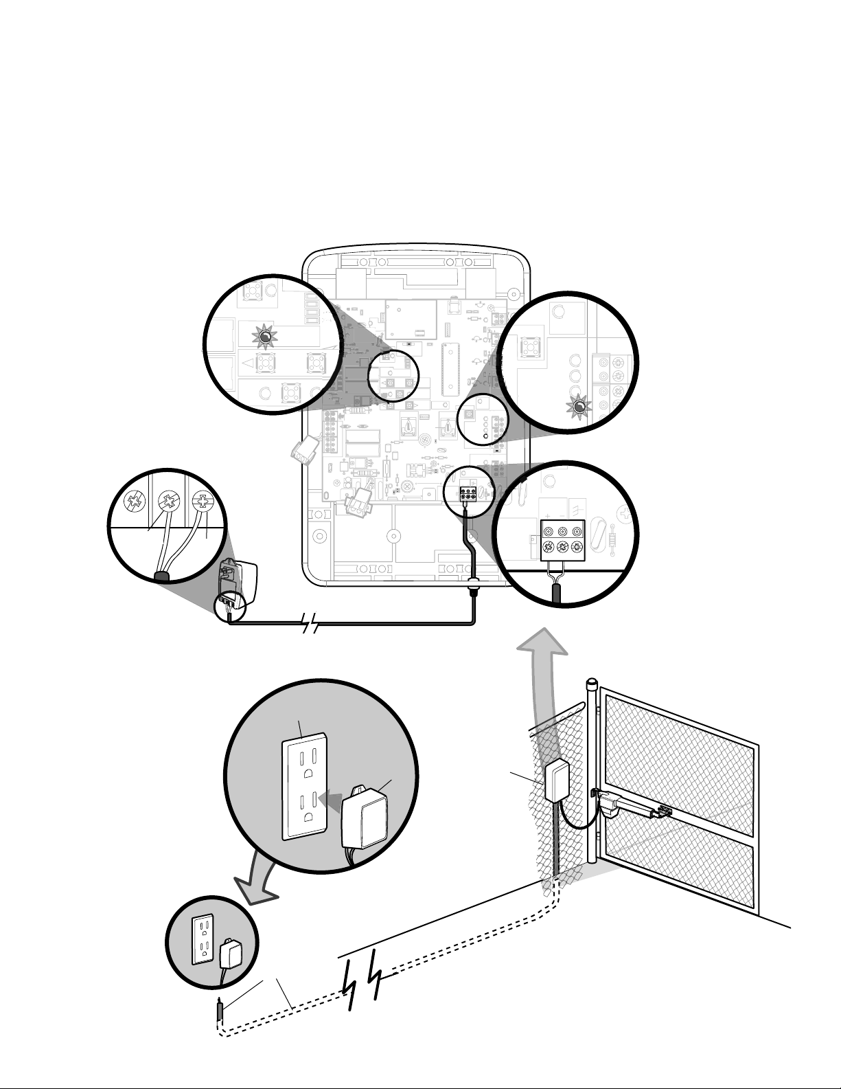
Connect indoor Transformer to Control Board
1
Insert wires from the indoor transformer through the bottom of the control box. Connect wires from the indoor
transformer to AC PWR/SOLAR terminal located on the control board as shown. Plug indoor transformer into a
dedicated outlet. The DIAGNOSTIC LED will blink once every 10 seconds and the STOP LED will light up for 10
seconds.
NOTE:
output may be used.
As an alternative to the supplied transformer, a UL listed 12 Volt, up to 30 Watt solar panel with Class 2
Common
14.5V
Indoor Transformer
Indoor Outlet
Indoor Transformer
PVC Conduit
Wiring 30
Control Box
Page 31

To reduce the risk of FIRE or INJURY to persons use ONLY
WARNING
CAUTION CAUTION
WARNING
WARNING
18
R93
L1
D42
K2
D1
Ø
Z22
P1
F2
MOV1
D1
Q12
U4
OFF
MAX
OPEN
SINGLE BUTTON
RESET
STOP
CHGR
OVLD
COM
COM
D129
Z4
U3
D2
D44
C11
C13
C12
D16
F9
R1Ø1
ØØ
K1
Q22
F3
K3
K4
R196
F1
Z12
GATE 2
GATE 1
MAGR
SOL
GR
WH
YL
BL
RD
BR
GR
WH
YL
BL
RD
BR
F7
24V
CTRL
OVLD
TIMER
RUNNING
GATE 2
SET
OPEN
LIMIT
SET
CLOSE
LIMIT
LEARN
LIMITS
GATE 1
LEARN
XMITTER
LOCK /
OFF
C69
OFF
MAX
J2
Ø
PWR
AC PWR
/SOLAR
D8
D4
R9
R329
R27
MOV2
R4
C2
BIPART DELAY
LOCK
GND
Z1
R1
R2
K5
F12
Q9
R9
Ø
F8
Q6
Q1
J19
R182
Ø1
C75
C73
C72
C71
C7
Ø
C66
C65
C68
C33
F11
R186
R42
Ø
R423
J24 J23 3
Ø
A 32V
3
Ø
A 32V
J21
30
30
C64
R22
U2
J18
K6
JU1
JU1
JU2
DB1
D36
R184
Chamberlain part 922GA for replacement batteries.
Connect Batteries
2
The batteries are charged in circuit by using the transformer (provided).
Locate the two white battery plugs on the left-hand side of the control box. Connect the plug from the battery to
connector on the control board.
NOTES:
should be changed every 3 years.
Batteries do not perform well in extremely cold temperatures. For locations where the temperatures are below -20°C
(-4°F) contact technical support.
Batteries will degrade over time depending on temperature and usage. For best performance, the batteries
Battery Connectors
Board Connectors
Battery Connection (GA400D Only)
OR
Battery Connection (GA420D Only)
Battery Connectors
LOCK
GATE 1
F8
Z12
GATE 2
F9
Board Connectors
R182
D36
D42
J21
J19
L1
K5
F12
ONONOFF
LEARN
Z1
R1
F1
30
3
A 32V
LOCK /
R2
XMITTER
BIPART DELAY
D1
K2
SET
K1
OPEN
LIMIT
Q9
R9
K4
OFF
D44
D8
K3
D4
Q22
R196
J24 J23 3
A 32V
U3
R9
D1
R329
F3
R27
C64
30
R22
U2
DB1
C1C1Ø1
SOL
GND
MAGR
R1
BR
GR
WH
YL
BL
RD
24V
R1R1ØØ
BR
GR
WH
YL
BL
RD
D16
P1
C66
C65
J18
C68
Z22
Q6
U4
C75
C7
C71
C72
C73
18
GATE 1
SET
LEARN
CLOSE
LIMITS
LIMIT
TIMER
GATE 2
RUNNING
J2
R186
MAX
OFF
C12
F7
Z4
C13
D2
D129
C69
R42
R423
JU1
C11
K6
JU2
JU1
C33
Q12
F11
R93
Q1
CTRL
PWR
OVLD
OPEN
SINGLE BUTTON
RESET
STOP
MAX
COM
COM
R184
F2
CHGR
MOV1
OVLD
AC PWR
C2
/SOLAR
MOV2
R4
Control Board
31 Wiring
Page 32
PROGRAMMING
Z22
R91
CLOSE
EDGE
R94
R92
R93
L1
R1
R2
Z1
K5
K6
K2
F3
10A 32V
D1
Ø
OPEN EDGE/ OPEN EDGE/
PHO T O
OPEN
PHO T O
CLOSE
PHO T O
R227
R2
Ø
7
Z2
Ø
R223
P1
Z9
Z8
F2
F6
D4
D2
R9
C64
JMPR1
R224
U4
CONTROL
INPUTS
FORCE
TIMER TO
CLOSE
OFF MAX
OPEN
SINGLE BUTTON
RESET
STOP
SHADOW
INTERRUPT
CHGR
OVLD
COM
COM
COM
FUSE
OPEN
LOOP
INPUTS
POWER
BATT 1 BATT 2
F1 20A 32V
R35
D9
Z3
Z4
U3
D1
F5
C11
C13
C12
D15
C2 R4
R1
Ø
1
R1
ØØ
R9
Ø
Q9
K1
R196
Q22
D8
K3
K4
D21
D22
C4
ACCESSORY
OVLD
D6
JMPR2
MOV1
MOV2
DB1
U2
Z12
24 VAC/
SOLAR
INPUT
GATE 2
ACCESSORY
POWER
MAGLOCK
ALARM
GATE 1
C
C
NC
NO
NO
GRN
WHT
YEL
BLU
RED
BRN
GRN
WHT
YEL
BLU
RED
BRN
F4
10A 32V
F7
24V
COM
OVLD
TIMER
RUNNING
GATE 2
SET
OPEN
LIMIT
SET
CLOSE
LIMIT
LEARN
LIMITS
DIAGNOSTIC
GATE 1
J4
LEARN
XMITTER
MAGLOCK
ON OFF
L1
D4
D2
R9
C64
JMPR1
U4
FORCE
R35
D9
Z3
Z4
U3
D1
D27 D27
C11
C12
D6
JMPR2
MOV1
DB1
U2
GATE 2
SET
CLOSE
LIMIT
LEARN
LIMITS
DIAGNOSTIC
GATE 1
MAGLOCK
ON OFF
SET
OPEN
LIMIT
OPEN EDGE/
D27
SET
CLOSE
DIAGNOSTIC
GATE 1
OPEN EDGE/
D27
SET
CLOSE
DIAGNOSTIC
GATE 1
OPEN EDGE/
D27
ACCESSORY
OVLD
OPEN EDGE/
D27
ACCESSORY
OVLD
SET
CLOSE
DIAGNOSTIC
GATE 1
OPEN EDGE/
D27
ACCESSORY
OVLD
SET
CLOSE
DIAGNOSTIC
GATE 1
Z22
R91
CLOSE
EDGE
R94
R92
R93
L1
R1
R2
Z1
K5
K6
K2
F3
10A 32V
D1
Ø
OPEN EDGE/ OPEN EDGE/
PHO T O
OPEN
PHO T O
CLOSE
PHO T O
R227
R2
Ø
7
Z2
Ø
R223
P1
Z9
Z8
F2
F6
D4
D2
R9
C64
JMPR1
R224
U4
CONTROL
INPUTS
FORCE
TIMER TO
CLOSE
OFF MAX
OPEN
SINGLE BUTTON
RESET
STOP
SHADOW
INTERRUPT
CHGR
OVLD
COM
COM
COM
FUSE
OPEN
LOOP
INPUTS
POWER
BATT 1 BATT 2
F1 20A 32V
R35
D9
Z3
Z4
U3
D1
F5
C11
C13
C12
D15
C2 R4
R1
Ø
1
R1
ØØ
R9
Ø
Q9
K1
R196
Q22
D8
K3
K4
D21
D22
C4
ACCESSORY
OVLD
D6
JMPR2
MOV1
MOV2
DB1
U2
Z12
24 VAC/
SOLAR
INPUT
GATE 2
ACCESSORY
POWER
MAGLOCK
ALARM
GATE 1
C
C
NC
NO
NO
GRN
WHT
YEL
BLU
RED
BRN
GRN
WHT
YEL
BLU
RED
BRN
F4
10A 32V
F7
24V
COM
OVLD
TIMER
RUNNING
GATE 2
SET
OPEN
LIMIT
SET
CLOSE
LIMIT
LEARN
LIMITS
DIAGNOSTIC
GATE 1
J4
LEARN
XMITTER
MAGLOCK
ON OFF
L1
D4
D2
R9
C64
JMPR1
U4
FORCE
R35
D9
Z3
Z4
U3
D1
D27 D27
C11
C12
D6
JMPR2
MOV1
DB1
U2
GATE 2
SET
CLOSE
LIMIT
LEARN
LIMITS
DIAGNOSTIC
GATE 1
MAGLOCK
ON OFF
SET
OPEN
LIMIT
Program Limits
The limits are internal settings that indicate when the gates are in the fully open position and the fully closed position. For
proper functionality, the limits must be learned during the installation process. The programmed limit process uses a
combination of buttons on the control board.
The specific buttons used for programming depends on which side of the gates the control box is mounted on and how
many operators the installation includes. Refer to pages 11-12 to determine if the gate is Left- or Right-handed and for
explanation of PULL-TO-OPEN and PUSH-TO-OPEN.
If a mistake is made during the programming process press the RESET button on the outside of the control box to start
over.
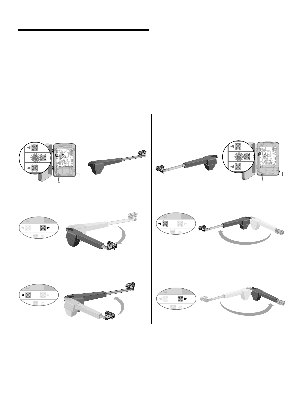
Single Arm Left-Hand Side Single Arm Right-Hand Side
NOTE:
automatically after 60 seconds of inactivity.
Program Open
With the gate in the closed position, press the LEARN
LIMITS button (SET OPEN LIMIT LED will blink).
LEARN LIMITS button
The “Learn Limits” mode can be exited at any time by pressing the
Program Open
With the gate in the closed position, press the LEARN
LIMITS button (SET OPEN LIMIT LED will blink).
RESET
button. The mode will time-out
LEARN LIMITS button
RESET
BUTTON
Press the GATE 1 right button to move gate to the desired
OPEN position. When gate is in the desired position, press
the LEARN LIMITS button again. Control board will beep.
Program Close
Press the GATE 1 left button to move gate to the desired
CLOSED position. When gate is in the desired closed
position, press the LEARN LIMITS button again.
RESET
BUTTON
Press the GATE 1 left button to move gate to the desired
OPEN position. When gate is in the desired position, press
the LEARN LIMITS button again. Control board will beep.
Program Close
When the SET CLOSE LIMIT LED blinks, press the
GATE 1 right button. When gate is in the desired closed
position, press the LEARN LIMITS button.
The control board beeps and the SET OPEN LIMIT and SET CLOSE LIMIT LEDs stop blinking,
programming is now complete.
Test the limits by pressing the SBC to open and close the gate.
NOTE:
programming making sure the gate is fully opened and closed for each respective limit. If the problem persists, refer to the
Troubleshooting section.
Programming 32
If the SET OPEN LIMIT LED is still blinking, the limits were not programmed successfully. Repeat the
Page 33
NOTES:
SET
CLOSE
DIAGNOSTIC
GATE 1
SET
CLOSE
DIAGNOSTIC
GATE 1
FORCE
GATE 2
SET
CLOSE
LIMIT
FORCE
GATE 2
SET
CLOSE
LIMITS
SET
OPEN
LIMIT
FORCE
GATE 2
SET
CLOSE
LIMIT
SET
CLOSE
DIAGNOSTIC
GATE 1
FORCE
GATE 2
SET
CLOSE
LIMIT
SET
CLOSE
DIAGNOSTIC
GATE 1
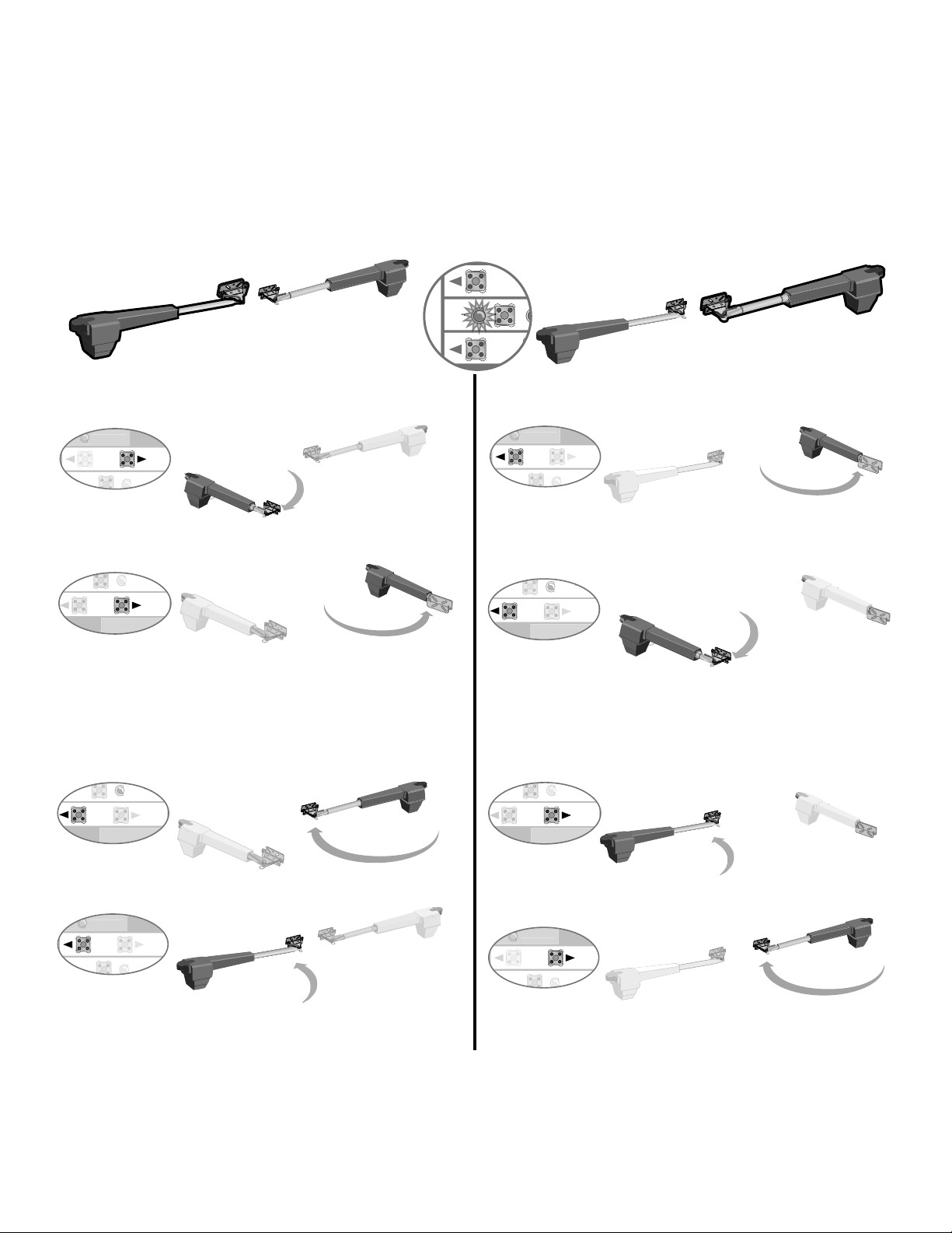
• If one gate is overlapping the other, the gate that is overlapping must be connected to GATE 1 so it will start moving
before the other gate; gate 2 may need to be closed fi rst if there is overlap or a gate lock is being used.
• The programming can be exited at any time by pressing the RESET button. Programming times-out automatically after
60 seconds of inactivity.
Dual Gate (Right-Side Primary Operator) Dual Gate (Right-Side Primary Operator)
Program Open Program Open
With the gate in the CLOSED position, press the LEARN
LIMITS button (SET OPEN LIMIT LED will blink).
With the gate in the CLOSED position, press the LEARN
LIMITS button (SET OPEN LIMIT LED will blink).
Press the GATE 1 right button to open the left side
operator.
Press the GATE 2 right button to move the right side
operator into the OPEN position.
Press the LEARN LIMITS button. Control board will beep.
Program Close
When the SET CLOSE LIMITS LED blinks, press the
GATE 2 left button to close the right operator.
Press the GATE 1 left button to open the right side
operator.
Press the GATE 2 left button to move the left side
operator into the OPEN position.
Press the LEARN LIMITS button. Control board will beep.
Program Close
When the SET CLOSE LIMITS LED blinks, press the
GATE 2 right button to close the left operator.
Press the GATE 1 left button to close the left operator.
Press the LEARN LIMITS button.
Press the GATE 1 right button to close the right operator.
Press the LEARN LIMITS button.
The control board beeps and the SET OPEN LIMIT and SET CLOSE LIMIT LEDs stop blinking,
programming is now complete.
Test the limits by pressing the SBC to open and close the gate.
NOTE:
If the SET OPEN LIMIT LED is still blinking, the limits were not programmed successfully. Repeat the
programming making sure the gate is fully opened and closed for each respective limit. If the problem persists, refer to the
Troubleshooting section.
33 Programming
Page 34
Force/Timer to Close/Party Mode Controls
WARNING WARNING
WARNING
Z22
R91
CLOSE
EDGE
R94
R92
R93
L1
R1
R2
Z1
K5
K6
K2
F3
10A 32V
D1
Ø
OPEN EDGE/
PHOTO
OPEN
PHOTO
CLOSE
PHOTO
R227
R2
Ø
7
Z2
Ø
R223
P1
Z9
Z8
F2
F6
D4R9
R224
U4
CONTROL
INPUTS
FORCE
TIMER TO
CLOSE
OFF MAX
OPEN
SINGLE BUTTON
RESET
STOP
SHADOW
INTERRUPT
CHGR
OVLD
COM
COM
COM
LOOP
INPUTS
POWER
BATT 1BATT 2
F1 20A 32V
R35
D9
Z3
Z4
U3
D1
C11
C13
C12
D15
C2R4
R1
Ø
1
R1
ØØ
R9
Ø
Q9
K1
R196
Q22
D8
K3
D22
C4
ACCESSORY
OVLD
MOV1
MOV2
Z12
24 VAC/
SOLAR
INPUT
GATE 2
ACCESSORY
POWER
MAGLOCK
ALARM
GATE 1
C
C
NC
NO
NO
GRN
WHT
YEL
BLU
BLU
RED
BRN
GRN
WHT
YEL
RED
BRN
GRN
WHT
YEL
BLU
RED
BRN
F4
10A 32V
F7
24V
COM
OVLD
GATE 2
DIAGNOSTIC
GATE 1
GATE 2
J4
LEARN
XMITTER
ON
D4
D2
Z9
Z8
Force Adjustment
The operator is equipped a with an obstruction sensing
feature. If the gate encounters an obstruction the operator
will automatically reverse direction and stop. Based on the
length and weight of the gate it may be necessary to make
force adjustments. The force adjustment should be high
enough that small objects such as branches or wind will
not cause nuisance interruptions but low enough to prevent
serious injury to a person or a vehicle.
To adjust the force:
Using the 3-button remote or the Single Button Control
(SBC) button on the control board, open and then close
the gate.
If the gate stops and or reverses before reaching the fully
open or closed position increase the force by turning the
force control slightly. Run operator through a complete
cycle.
NOTE:
movement, so seasonal adjustment may be required. The
force control is factory set to the mid position.
Weather conditions can affect the gate
FORCE
Without a properly installed safety reversal system, persons
(particularly small children) could be SERIOUSLY INJURED or
KILLED by a closing gate.
• Too much force on gate will interfere with proper operation
of safety reversal system.
• NEVER increase force beyond minimum amount required to
close gate.
• NEVER use force adjustments to compensate for a binding or
sticking gate.
• If one control (force or travel limits) is adjusted, the other
control may also need adjustment.
• After ANY adjustments are made, the safety reversal system
MUST be tested. Gate MUST reverse on contact with a rigid
object.
Party Mode
TTC can be temporarily disabled by pressing RESET
button (located on the outside side of the control box)
when the gate is fully open. This will allow the gate to
remain open until another command is received. Following
this command, TTC is re-enabled at the previously set
time period.
Minimum Force
Maximum Force
Timer-to-Close (TTC)
The TIMER TO CLOSE feature can be set to
automatically close the gate after a specified time period.
If the TTC is set to the OFF position, then the gate will
remain open until the operator receives another
command from a remote control or SBC.
To set the TIMER TO CLOSE:
Rotate the TIMER TO CLOSE dial to the desired setting.
The range is 0 to 180 seconds, 0 seconds is OFF.
NOTE:
on the control board prior to the TTC expiring will close
the gate. The TTC is reset by any signals from the loops,
close edges, and close safety sensors (IR’s).
Any radio command, SBC, or CLOSE command
TIMER TO
CLOSE
FORCE
TIMER TO
CLOSE
OFF MAX
OFF MAX
34 Programming
Page 35
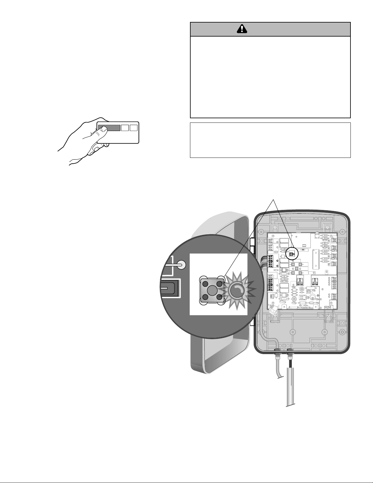
Z22
R91
CLOSE
EDGE
R94
R92
R93
L1
R1
R2
Z1
K5
K6
K2
F3
10A 32V
D1
Ø
OPEN EDGE/
PHO T O
OPEN
PHO T O
CLOSE
PHO T O
R227
R2
Ø
7
Z2
Ø
R223
P1
Z9
Z8
F2
F6
D4 R9
R224
U4
CONTROL
INPUTS
FORCE
TIMER TO
CLOSE
OFF MAX
OPEN
SINGLE BUTTON
RESET
STOP
SHADOW
INTERRUPT
CHGR
OVLD
COM
COM
COM
LOOP
INPUTS
POWER
F1 20A 32V
R35
D9
Z3
Z4
U3
C11
C13
C12
D15
C2 R4
R1
Ø
1
R1
ØØ
R9
Ø
Q9
K1
R196
Q22
D8
K3
D22
C4
ACCESSORY
OVLD
MOV1
MOV2
Z12
24 VAC/
SOLAR
INPUT
GATE 2
ACCESSORY
POWER
MAGLOCK
ALARM
GATE 1
C
C
NC
NO
NO
GRN
WHT
YEL
BLU
BLU
RED
BRN
GRN
WHT
YEL
RED
BRN
GRN
WHT
YEL
BLU
RED
BRN
F4
10A 32V
F7
24V
COM
OVLD
GATE 2
DIAGNOSTIC
GATE 1
GATE 2
J4
LEARN
XMITTER
ON
R1
To Add or Reprogram a Remote Control
WARNING WARNING
WARNING
(not provided)
1. Press LEARN XMITTER button and release (LED will
light up).
2. Press remote button, the LED will flash, alarm output
will activate twice.
3. Repeat steps 1 and 2 until all remote controls are
programmed (9 remote controls maximum).
NOTE:
For highest level of security, we recommend the
Security✚® line of products. Refer to Accessories.
To Add a Wireless Keyless Entry (not provided)
To prevent possible SERIOUS INJURY or DEATH from a
moving gate or garage door:
• ALWAYS keep remote controls out of reach of children.
NEVER permit children to operate, or play with remote
control transmitters.
• Activate gate or door ONLY when it can be seen clearly, is
properly adjusted, and there are no obstructions to door
travel.
• ALWAYS keep gate or garage door in sight until completely
closed. NEVER permit anyone to cross path of moving gate
or door.
NOTIC E: To comply wi th FCC and or Industr y Canada (IC) rule s, adjustment or modificat ions of
this receiver and/or t ransmit ter are prohibited, except for changing the code set ting or replacing
the battery. THERE ARE NO OT HER USER SERV ICEABLE PARTS.
Tested to Comply with FCC St andards FOR HOME OR OFFICE USE. Operation is subject to the
following two conditions: (1) this device may n ot cause har mful inter ference, a nd (2) this d evice
must ac cept any interference received, including interference th at may cause undesired
operation.
Remote Control LEARN XMITTER Button
1. Press LEARN XMITTER button and release (LED will
light up).
2. Enter a four digit personal identification number (PIN)
of your choice on the keypad.
3. Then press ENTER, the LED will flash, alarm output
will activate twice.
To Erase All Codes
To deactivate any unwanted remote controls or keyless
entries, first erase all codes:
Press and hold the LEARN XMITTER button on control
board until the learn indicator light goes out (approximately
6 seconds). All previous codes are now erased.
Reprogram each remote control or keyless entry you wish
to use.
LEARN
XMITTER
Make sure the rubber seal around the cover is intact and close the cover. Secure the control box cover with screws (4).
Installation is complete.
35 Programming
Page 36
WARNING
WARNING WARNING
OPERATION AND MAINTENANCE
RESET
IMPORTANT SAFETY INSTRUCTIONS
To reduce the risk of SEVERE INJURY or DEATH:
1. READ AND FOLLOW ALL INSTRUCTIONS.
2. NEVER let children operate or play with gate controls. Keep
the remote control away from children.
3. ALWAYS keep people and objects away from the gate. NO
ONE SHOULD CROSS THE PATH OF THE MOVING GATE.
4. Test the gate operator monthly. The gate MUST reverse on
contact with a rigid object or stop when an object activates
the non-contact sensors. After adjusting the force or the
limit of travel, retest the gate operator. Failure to adjust and
retest the gate operator properly can increase the risk of
INJURY or DEATH.
Using Your Gate Operator
Your operator will operate with up to nine Security✚®
remote controls and one Security✚® Keyless Entry System.
If you purchase a new remote, or if you wish to deactivate
any remote, follow the instructions in the Programming
section.
Activate your operator with any of the following:
Hand Held Remote Control (See Accessories): Hold
push button down until the gate begins to move. While gate
is moving, the next command sent from the remote will stop
the gate. Next command will reverse the gate direction.
Keyless Entry (See Accessories): If provided with your
gate operator, it must be programmed before use. See
Programming
Vehicle Exit Sensor: See accessory page.
.
5. Use the emergency release ONLY when the gate is not
moving.
6. KEEP GATES PROPERLY MAINTAINED. Read the owner’s
manual. Have a qualified service person make repairs to
gate hardware.
7. The entrance is for vehicles ONLY. Pedestrians MUST use
separate entrance.
8. Disconnect ALL power BEFORE performing ANY
maintenance.
9.
SAVE THESE INSTRUCTIONS.
Automatic Timer To Close Feature
The Timer-To-Close (TTC) Feature comes
from the factory in the OFF setting.
The “TIMER RUNNING LED” will flash once
for every second of adjusted time. The gate(s)
must fully open for the timer feature to be
active and close the gate(s). Any radio
command or pressing the single button on the control
board prior to the TCC time expiring will close the gate.
The TTC is reset by any signals from the loops, close
edges, and close safety sensors (IR’s).
TIMER TO
CLOSE
OFF
MAX
Entrapment Features
When the operator is activated (with the safety sensors
correctly installed and aligned) and the safety sensors
encounter an obstruction, the following will occur:
Opening Cycle: Gate will stop, reverse direction for
approximately 2 seconds and then stop. The next
command will continue the gate in the close direction.
Closing Cycle: Gate will stop, reverse direction for
approximately 2 seconds and then stop. The next
command will open the gate.
Alarm Sounds
The operator alarm will sound under the following condition:
If gate encounters two consecutive obstructions, the
operator will stop, the alarm will sound (up to 5 minutes)
and the control board will require resetting. Reset the
control board by pressing the “Reset Button” located on the
outside of the control box. No commands at this time will
operate gate. After the operator is reset, normal functions
will be available.
Operation and Maintenance 36
Party mode
If the Timer-to-Close feature is enabled and you would like
the gate to remain open, simply push the reset button
(located on the outside of the control box). The next
command given to the operator will close the gate and
return the operator to normal operation.
Sleep mode (battery conservation)
Sleep Mode (Battery Conservation): The operator enters
sleep mode 10 seconds after the last command is given.
The diagnostic LED will blink in this mode. The safety
sensors (photo eyes) indicator LEDs will not be on. The
next operation command will return
the operator to normal operation.
T
E
RES
Page 37

Manual Release
In case of a power failure, the operator can be disengaged from the gate. Follow the directions below to disconnect and
reconnect the operator to the gate.
Release
1. Remove the hairpin clip and release pin that secures the gate bracket to the gate.
2. Move operator away from gate and out of the way of gate travel.
If a gate lock (automatic or manual) is used; disengage the lock.
Engage
1. Align the hole in the arm with the hole in the gate bracket.
2. Insert release pin and secure with hairpin clip.
Release Pin
Gate Bracket
Hairpin Clip
Maintenance
Description Task 1 Month 3 Months 6 Months 12 Months 3 Years
Entrapment
Protection Systems
Manual Release
Gate
Accessories
Electrical
Mounting Hardware
Batteries
Total Unit
Check for proper operation
Check and operate
Inspect for wear or damage
Check all for proper operation
Inspect all wire connections
Check for tightness
Replace
Inspect for wear or damage
● ● ● ● ●
● ● ●
● ● ●
● ● ●
● ● ●
● ● ●
●
● ● ●
CHECK AT LEAST ONCE EVERY
NOTES:
1. Disconnect power before servicing.
2. Severe or high cycle usage will require more frequent
maintenance checks.
3. Inspection and service should always be performed
anytime a malfunction is observed or suspected.
4. When servicing, please do some “house cleaning” of the
operator and the area around the operator. Pick up any
debris in the area. Clean the operator as needed.
5. It is suggested that while at the site voltage readings be
taken at the operator. Using a Digital Voltmeter, verify
that the incoming voltage to the operator it is within ten
percent of the operator’s rating.
6. See page 34 for instructions on how to check gate force
and sensitivity adjustments.
37 Operation and Maintenance
Page 38

Wiring Diagram
To protect against fire and electrocution:
To protect against fire and electrocution:
• DISCONNECT power and battery BEFORE installing or
• DISCONNECT power and battery BEFORE installing or servicing operator.
servicing operator.
For continued protection against fire:
For continued protection against fire:
• Replace ONLY with fuse of same type and rating.
• Replace ONLY with fuse of same type and rating.
Fault Alarm
1. Antenna Input
2. Close Edge*
3. Open Edge/Photo*
4. Open Photo*
5. Close Photo*
6. Control Inputs*
7. Loop Inputs*
8. AC PWR/SOLAR
23
* Class 2 circuit 15 v maximum output
2. Close edge
9. Gate 2
10. Accessor y Power*
3. Open edge/photo eye
11. Gate 1
12. Lock (Solenoid/Maglock) Output*
4. Open photo eye
13. Alar m Output*
5. Close photo eye
14. Batter y 1 Connector
15. Batter y 2 Connector
6. Control inputs
16. Lock/BiPart Delay
7. Loop inputs
*Class 2 circuit 15 V maximum output
17. Learn Xmitter
18. Primary Gate Jog
19. Learn Limits
20. Secondary Gate Jog
21. Force
22. Timer To Close
23. Receiver Module
24. Fuses (20 Amp)
10. Accessory power
12. Automatic gate lock
13. Fault alarm
1
Automatic Gate Lock
(optional)
Gate 1 (Master)
Gate 2 (Second)
19
J2
Ø
22
C12
C75
TIMER
RUNNIN G
R186
R42
Ø
R423
K6
P1
U4
TIMER TO
CLOSE
OFF MAX
F7
C13
D2
D129
C69
J18
SINGLE BUTTON
F2
MOV1
8
C66 C65
SINGLE BUTTON
CHGR
OVLD
AC PWR
/SOLAR
F11
R93
SHADOW
INTERRUPT
Q6
Q12
Q1
CTRL
OVLD
OPEN
RESET
STOP
CTRL PWR
CTRL PWR
CTRL
PWR
C68
C33
Z22
CLOSE
EDGE
OPEN EDGE/
PHOTO
OPEN
PHOTO
CLOSE
PHOTO
CONTROL
INPUTS
*
2
EDGE
916GA SAFETY SENSORS
*
3
OR
EDGE
916GA SAFETY SENSORS
*
4
*
916GA SAFETY SENSORS
5
OPEN (EXI T LOOP)
SINGLE BUTTON (SBC)
RESET
STOP
R184
*
LOOP
INPUTS
PWR
C2
MOV2
R4
6
*
7
SHADOW LOOP
INTERRUPT LOOP
OPTIONAL GROUND ROD
*
13
ALARM
BLK
RED
*
12
RED
BLK
11
BRN
GRN
WHT
YEL
BLU
RED
*
10
9
BRN
GRN
WHT
YEL
BLU
RED
LOCK
GATE 1
ACCESSORY
POWER
GATE 2
F9
SOL
GND
MAGR
BR
GR
WH
YL
BL
RD
F8
Z12
12 V
BR
GR
WH
YL
BL
RD
24
15
R182
C1
Ø1
D36
D42
Z1
R2
R1
R9
ØØ
R1
R1Ø1
D16
F1
J21
30
3
Ø
A 32V
14
D1
Ø
Q22
ACCESSORY
0VLD
K5
F12
Ø
K2
K1
Q9
R196
J24 J23 3
F3
Ø
A 32V
J19
ON OFF
LEARN
XMITTER
LOCK /
BIPART DELAY
17
DIAGNOSTIC
SET
OPEN
LIMIT
20
FORCE
21
K4
K3
2Ø
NOTE: Batteries MUST
be connected to operate.
OFF MAX
D44
D8
D4
R9
C64
U2
U3
D1
R329
R27
R22
DB1
C7
C71
C72
C73
Ø
SET
CLOSE
LIMIT
C11
18
18
JU2
GATE 1
GATE 2
JU1
16
LEARN
LIMITS
Z4
OR OPTIONAL SOLAR PANEL
Operation and Maintenance 38
RED
BLK
NOTE: For all installations use
the 14.5V output on transformer.
Page 39

Diagnostic Chart
Your gate operator is programmed with self-diagnostic capabilities. The diagnostic LED will flash a number of times then
pause signifying it has found a potential issue. Consult Diagnostic Chart below.
1 FLASH
Power ON
2 FLASHES
STOP not connected
3 FLASHES
Low Battery Voltage
4 FLASHES
Low Battery
Capacity
5 FLASHES
RPM Reversal Gate 1
or Arm Disconnected
Normal Operation
Stop is not connected.
• Press the RESET button and make sure the STOP LED turns on.
• Check to make sure the jumper wire is connected between the COM and STOP input
on the control board. Stop is a normally closed input.
Battery voltage is below the recommended operating level.
• Battery may not be properly charged. Disconnect all batteries and make sure AC
power or solar power is connected. Verify AC power outlet.
• Verify that the battery fuses are intact and not blown. Replace blown fuses with same
type and rating.
• Batteries are no longer capable of holding a charge due to age or excessive depleting
of the battery. Replace the batteries (see accessories page). Dispose of old batteries
properly.
Gate 1 has encountered an obstruction or the arm is disconnected.
• Make sure the path of the gate is clear and the gate moves freely.
• Incorrect or poor connection to Gate 1 arm. Check the green and white wires on the
motor arm to make sure connections are correct and secure.
• Bad arm or control board. Press the LEARN LIMITS button and press the GATE 1
buttons to move the arm. If the arm does not move continuously, disconnect arm from
Gate 1 and connect the arm to the Gate 2 connector and repeat the attempt to move
the arm. If the arm does not move continuously on either Gate 1 or 2, replace the arm.
6 FLASHES
Force Reversal Gate 1
7 FLASHES
RPM Reversal Gate 2
or Arm Disconnected
8 FLASHES
Force Reversal Gate 2
9-11 FLASHES
Potential chip failure
39 Operation and Maintenance
Gate 1 has encountered an obstruction.
• Make sure the path of the gate is clear and the gate moves freely.
• If there is no obstruction the force adjustment is set too low. Increase the force setting
and verify that the gate moves without reversing and will reverse if an obstruction is
encountered.
Gate 2 has encountered an obstruction or the arm is disconnected.
• Make sure the path of the gate is clear and the gate moves freely.
• Incorrect or poor connection to Gate 2 arm. Check the green and white wires on the
motor arm to make sure connections are correct and secure.
• Bad arm or control board. Press the LEARN LIMITS button and press the GATE 2
buttons to move the arm. If the arm does not move continuously, disconnect arm from
Gate 2 and connect the arm to the Gate 1 connector and repeat the attempt to move
the arm. If the arm does not move continuously on either Gate 1 or 2, replace the arm.
Gate 2 has encountered an obstruction.
• Make sure the path of the gate is clear and the gate moves freely.
• If there is no obstruction the force adjustment is set too low. Increase the force setting
and verify that the gate moves without reversing and will reverse if an obstruction is
encountered.
Potential RAM, Flash, or EEPROM failure.
• Turn power off and on.
• If problem does not resolve itself by turning power off and on, replace the control
board.
Page 40

Troubleshooting
SYMPTOM POSSIBLE SOLUTION
Operator does not run. • Power not connected. Make sure the AC/Solar input is connected and that at least
Diagnostic LED not on. one battery is connected with the corresponding fuse intact.
• Low or defective battery. Check the battery to make sure that the red wire goes to
the positive terminal of the battery and the black wire goes to the negative terminal
of the battery. Replace the battery if the open circuit voltage is below 11.5Vdc.
• Bad control board. Call technical support for more options.
Operator powers up but • Low or defective battery. At least one charged battery must be connected for the
does not run. unit to operate. Verify the battery fuse is intact. Check battery connections and
battery voltage to be above 11.5V Replace batteries if necessary.
• STOP button connection loose or disconnected. Press the RESET button and verify
that the STOP LED lights up and then turns off after 10 seconds. Verify the wire
connects between the STOP and CTRL PWR terminals.
• Obstruction blocking safety sensors. Press the RESET button and verify that all the
safety LEDs (OPEN EDGE/PHOTO, OPEN PHOTO, CLOSE PHOTO) are OFF. If
any are ON, clear any obstructions and verify the LED turns off
off after 10 seconds when the unit goes to sleep.
• (Optional Accessory) Safety edge is damaged or on an obstruction. Press the
off after 10 seconds when the unit goes to sleep.
• (Optional Accessory) Interrupt loop or Shadow loop is obstructed. Press the RESET
• Bad control board. Call technical support for help with replacement parts.
Relays “click” when remote • Battery not connected. At least one charged battery must be connected for the unit
control or single button to operate. Verify battery fuse is intact. Check battery connections and battery
control (SBC) command voltage to be above 11.5V. Replace batteries if necessary.
is given, but the operator • Arm cable loose or disconnected. Verify that all of the wires, especially the red and
does not move. blue wires, going to the arm are secure and that the connector is properly mated to
the header.
• Arm is jammed or incorrectly installed. Disconnect the motor housing from the arm
• Bad control board. Call technical support for help with replacement parts.
NOTE:
RESET button and verify that the Safety LEDs (OPEN EDGE and CLOSE EDGE/
PHOTO) are OFF. If either is ON, clear any obstructions and verify the LED turns
off.
NOTE:
button and verify that the INTERRUPT and SHADOW LEDs are OFF. If either is on,
check the loop detector and its wiring to insure that it is not incorrectly being
triggered.
and verify that the arm moves freely. With the motor housing still disconnected,
enter the Learn Limits mode and verify that the motor spins. Reconnect the motor
housing to the arm and make sure that all 4 screws are securely tightened and that
the motor seats correctly against the worm drive. Relearn limits for the operator.
The RESET button may need to be hit multiple times since the LEDs turn
The RESET button may need to be hit multiple times since the LEDs turn
Operation and Maintenance 40
Page 41

SYMPTOM POSSIBLE SOLUTION
The arm moves but cannot • Arm does not extend or contract enough during travel. The arm piston must extend
exit Learn Limits mode. and contract close to its full length to Learn Limits. Adjust the arm mounting so that
Cannot learn limits. this can be achieved.
• Motor cable wire not connected. Make sure that all the motor wires are connected
properly.
• Motor housing is not properly seated. Make sure that the motor housing for the
arm(s) is properly seated so there are no gaps between the motor housing and arm
assembly. Make sure all 4 screws are tightened.
Gate does not fully open or • Over extending or contracting arm. Disconnect the motor housing from the arm and
close when trying to learn make sure that the arm moves freely throughout the full length of travel. Adjust arm
limits. mounting and positioning if necessary.
• Arm is interfering with the gate mount bracket. Examine the hinge point where the
arm mounts to the gate post. Make sure that the arm housing does not hit or
interfere with the gate post or mounting bracket throughout the full length of travel.
Adjust the arm mounting and positioning if necessary.
• Gate is excessively heavy or hinges are bad. Verify that the gate is within the ratings
for this product. Disconnect the arms and verify that both gates swing easily.
Lubricate or replace hinges as necessary.
Unit does not respond to • Battery not connected. At least one charged battery must be connected for the unit
single button control (SBC) to operate. Verify the battery fuse is intact. Check battery connections and battery
command. voltage to be above 11.5V. Replace batteries if necessary.
• STOP button connection loose or disconnected. Press the RESET button and verify
that the STOP LED lights up and then turns off after 10 seconds. Verify the wire
connects between STOP and CTRL PWR terminals.
• Single Button Control (SBC) button connection loose. Check wiring for SBC button.
Use the on-board single button to verify operator will respond.
• Bad control board. Call technical support for help with replacement parts.
Unit does not respond to • Battery not connected. At least one charged battery must be connected for the unit
remote control command. to operate. Verify battery fuse is intact. Check battery connections and battery
voltage to be above 11.5V. Replace batteries if necessary.
• STOP button connection loose or disconnected. Press the RESET button and verify
that the STOP LED lights up and then turns off after 10 seconds. Verify the wire
connects between the STOP and CTRL PWR terminals.
• Radio module not plugged in. Verify the green Radio module (located next to the
coaxial connector) is properly mated with both 4-pin connectors.
• Antenna not connected. Verify the antenna and coaxial cable are properly
connected to the control board.
• Transmitter not learned. Refer to Programming Remote Control section for steps to
program the transmitter.
• Bad control board. Call technical support for help with replacement parts.
Gate stops and reverses • Obstruction sensed. Check safety devices and gate for obstructions.
immediately after it starts • A fault has occurred. Check Diagnostic LED for possible error codes.
moving. • Force set too low. Adjust FORCE setting until gate completes a full open/close cycle
without reversing. The force setting may need to be adjusted in cold weather, as the
gate will not move freely.
• Loops are reversed. Make sure that the Safety loop and Shadow loop are
connected properly. The gate may trigger the Shadow loop as it moves, so it must
be connected to the correct input.
• Low or defective battery. At least one charged battery must be connected for the
units to operate. Verify battery fuse is intact. Check battery connections and battery
voltage to be above 11.5V. Replace batteries if necessary.
41 Operation and Maintenance
Page 42

SYMPTOM POSSIBLE SOLUTION
Gate opens but does not • An open input is continuously activated. Check the open loop or vehicle probe to
close. make sure they are clear of objects. Verify connections and operation for these
devices.
• Low battery. Measure the voltage across the battery. Voltage should be above
11.5Vdc. Replace battery if required.
• (Optional Accessory) Entry system output is connected to the OPEN input, and is
“stuck” opening. Verify entry system connections and operations.
• Obstruction blocking close photo eyes, shadow loop, or safety loop. Check eyes for
alignment and verify all connections and operation for safety devices.
• (Optional Accessory) Close safety edge is damaged or on an obstruction. Verify
operation and connection of close edge.
Gate does not close • Verify that the Timer to Close is ON and adjusted to desired delay.
automatically with Timer to • Gate opened by a force obstruction reversal. Check the Diagnostic LED and clear
Close enabled. gate path of any obstructions.
• The Interrupt loop or Shadow loop is obstructed (optional accessories).
• Obstructed close safety sensor or safety edge (optional accessory). Check
connections and operations of safety devices.
• Low battery. Measure the voltage across the battery. Voltage should be above
11.5Vdc. Replace battery is required.
• An open input is continuously activated. Check the open loop or vehicle probe to
make sure they are clear of objects. Verify connections and operation for these
devices.
• (Optional Accessory) Entry system output is connected to the OPEN input, and is
“stuck” opening. Verify entry system connections and operation.
• Operator in “Party” mode after RESET button pressed while at the OPEN limit. Use
a remote or the SBC to close the gate and reopen it. Verify that the
TIMER RUNNING LED is flashing.
Alarm constantly sounds • Double entrapment occurred. Two successive obstructions were encountered while
for 5 minutes. Sounds moving the gate. Press the RESET button and ensure that the gate path is clear of
whenever a command is all obstructions. Check the FORCE setting to make sure it is properly set.
issued.
Alarm is beeping 3 times on • Low battery. Measure the voltage across the battery. Voltage should be above
a command. 11.5Vdc. Replace battery if required.
Gate runs too slow. • Open and Close Limits are set too close together. If the Open and Close Limits are
set within the ramp down distance of each other, the gate will run at slow speed all
the time.
• The gate is starting within the ramp down distance from the Open or Close Limit.
Gate will run slow to limits if motion is started within the ramp-down distance from
the limit.
Gate 2 closes before Gate 1. • Lock/Bipart Delay not set. Slide the Lock/Bipart Delay switch to ON. Verify that
Gate 1 starts moving first on open and last on close.
• Gate is excessively heavy or hinges are bad. Verify that the gate is within the ratings
for this product. Disconnect the arms and verify that both gates swing easily.
Lubricate or replace hinges as necessary.
• Gate is unbalanced. Disconnect the arms and verify that both gates swing easily in
both directions. If the gates are harder to move in one direction verses the other, the
gate is not properly balanced and the hinges must be adjusted.
• Bad motor connection. Check the motor wires and connections for possible loose or
corroded terminals.
Alarm beeps when running. • Low battery. Measure the voltage across the battery. Voltage should be above
11.5Vdc. Replace battery if required.
Gate does not open/close at • In windy areas, an automatic gate lock for close and a hard stop for open is
the same place each time. recommended to ensure the gate stops in the same place each time.
• Periodic limit adjustments may be necessary.
Operation and Maintenance 42
Page 43
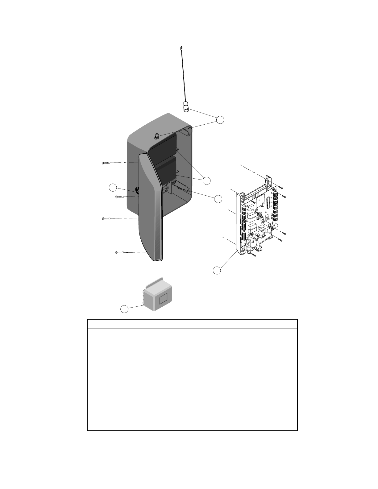
Repair Parts
Control Box
3
4
6
2
1
5
ITEM PART # DESCRIPTION QTY
1 K1A6426 Control Board with
Mounting Bracket 1
2 K23-19380 Reset Switch 1
3 K74-34392 Antenna 1
4 922GA Battery with Harness 1
5 K204B0195 Indoor Transformer 1
6 K29-20095 Alarm 1
Not Shown
K74-33975 Complete Control Box (without battery) 1
K1A5747 Receiver Module - 315MHz 1
K1A5747-2 Receiver Module - 390MHz (optional) 1
NOTE:
The fuse is a standard 20 Amp fuse that is available from your local
automotive store.
43 Operation and Maintenance
Page 44
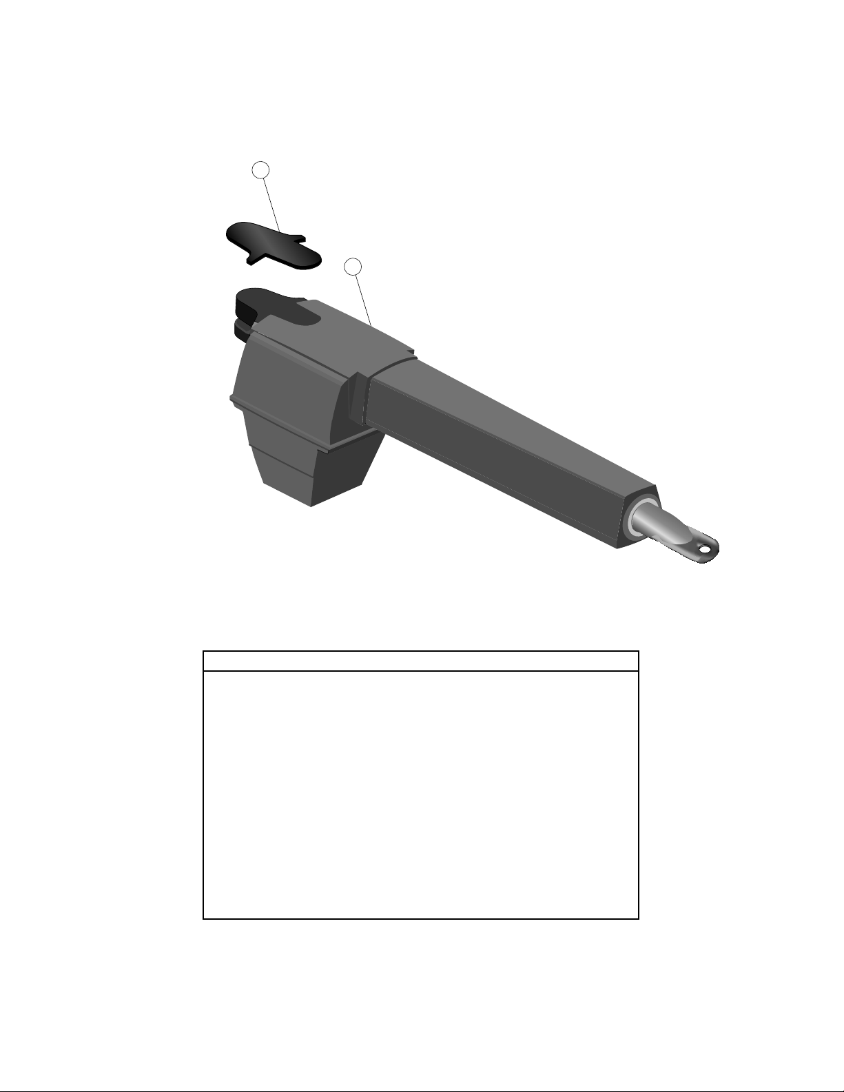
1
2
Repair Parts
Gate Operator Arm
ITEM PART # DESCRIPTION QTY
1 K-41ADBL-0004 Arm Cover 1
2 K-LA-6 Complete Arm Assembly
Includes: Arm, Motor and
Plastic Cover 1
Not Shown
K-DBL-0095SA Hardware Kit
Includes: One Extension
Bracket, One Gate Bracket,
One Post Bracket and
One Hardware Bag) 1
01-33859 Owner’s Manual 1
01-33859SP Owner’s Manual - Spanish 1
K-41ADBL-1011SA Screws for housing (pack of 4)
Operation and Maintenance 44
Page 45

OPEN
OPEN
Accessories
OPEN
OPEN
OPEN
7
OPEN
CLOSE
OPEN
OPEN
CLOSE
TO
PRESS
RING
OPEN
CLOSE
953D
916GA
915GA
917GA
3-Button SECURITY✚® Remote
Control:
Includes visor clip.
Protector System® Safety Sensors:
The Safety Sensors are intended
for installation with the operators
covered in this manual. To order call:
1-866-826-4943 or visit our website
www.chamberlain-diy.com.
Automatic Gate Lock:
Solenoid-driven lock that automatically
unlocks when gate is open and locks
when gate is closed. Can be mounted
onto gate or post. Can be released in
case of emergency.
Low Voltage Wire (100')
Low voltage wire is required to connect
the transformer to the control box. Also
can be used to connect optional safety
sensors to the control box. UL
approved for burial.
940D
SECURITY✚® Keyless Entry:
Enables homeowner to operate gate
operator from outside by entering a
four digit code on a specially designed
keyboard.
956D
3-Button Mini-Remote Control with
SECURITY✚®:
With key ring and fastening strip.
914GA
Gate Arm Pin Lock:
The pin lock kit is designed to prevent
disconnection of the gate operator and
the gate while providing a means to
open the gate in case of power failure.
921GA Vehicle Exit Sensor:
One piece outdoor buried vehicle
motion detector with sensing probe is
housed in a small relay type housing
so it is easy to integrate with gate,
providing for free exit only.
918GA
Low Voltage Wire (250')
Low voltage wire is required to connect
the transformer to the control box. Also
can be used to connect optional safety
sensors to the control box. UL
approved for burial.
Wireless Gate Doorbell920GA
Allows guests to ring a doorbell
in the house from the keypad.
Homeowner can open gate
from inside the home using the
included remote control button.
No wiring required. Keypad can
be programmed to allow access to
selected guests using a 4 digit code.
919GA
922GA
Push-To-Open Bracket:
Used to allow the gate operator to
push the gate open.
Gate Access System Battery
The Gate Access System Battery is
designed to add a battery for solar
applications or as a replacement
battery (includes cable harness).
45 Operation and Maintenance
Page 46

WARRANTY POLICY
CHAMBERLAIN ONE YEAR LIMITED WARRANTY
The Chamberlain Group, Inc. warrants to the first retail purchaser of this product, for the structure in which this product is originally
installed, that it is free from defect in materials and/or workmanship for a period of ONE year from the date of purchase. The proper
operation of this product is dependent on your compliance with the instructions regarding installation, operation, maintenance and
testing. Failure to comply strictly with those instructions will void this limited warranty in its entirety.
If, during the limited warranty period, this product appears to contain a defect covered by this limited warranty, call 1-866-826-4943,
toll free, before dismantling this product. Then send this product, pre-paid and insured, to our service center for warranty repair. You
will be advised of shipping instructions when you call. Please include a brief description of the problem and a dated proof-ofpurchase receipt with any product returned for warranty repair. Products returned to Seller for warranty repair, which upon receipt
by Seller are confirmed to be defective and covered by this limited warranty, will be repaired or replaced (at Seller’s sole option) at no
cost to you and returned pre-paid. Defective parts will be repaired or replaced with new or factory-rebuilt parts at Seller’s sole
option.
ALL IMPLIED WARRANTIES FOR THE PRODUCT, INCLUDING BUT NOT LIMITED TO ANY IMPLIED WARRANTIES OF
MERCHANTABILITY AND FITNESS FOR A PARTICULAR PURPOSE, ARE LIMITED IN DURATION TO THE ONE YEAR LIMITED
WARRANTY PERIOD SET FORTH ABOVE, AND NO IMPLIED WARRANTIES WILL EXIST OR APPLY AFTER SUCH PERIOD. Some
States do not allow limitations on how long an implied warranty lasts, so the above limitation may not apply to you. THIS
LIMITED WARRANTY DOES NOT COVER NON-DEFECT DAMAGE, DAMAGE CAUSED BY IMPROPER INSTALLATION, OPERATION
OR CARE (INCLUDING, BUT NOT LIMITED TO ABUSE, MISUSE, FAILURE TO PROVIDE REASONABLE AND NECESSARY
MAINTENANCE, UNAUTHORIZED REPAIRS OR ANY ALTERATIONS TO THIS PRODUCT), LABOR CHARGES FOR REINSTALLING A
REPAIRED OR REPLACED UNIT, OR REPLACEMENT OF BATTERIES.
THIS LIMITED WARRANTY DOES NOT COVER ANY PROBLEMS WITH, OR RELATING TO, THE GATE OR GATE HARDWARE,
INCLUDING BUT NOT LIMITED TO THE GATE SPRINGS, GATE ROLLERS, GATE ALIGNMENT OR HINGES. THIS LIMITED
WARRANTY ALSO DOES NOT COVER ANY PROBLEMS CAUSED BY INTERFERENCE. ANY SERVICE CALL THAT DETERMINES THE
PROBLEM HAS BEEN CAUSED BY ANY OF THESE ITEMS COULD RESULT IN A FEE TO YOU.
UNDER NO CIRCUMSTANCES SHALL SELLER BE LIABLE FOR CONSEQUENTIAL, INCIDENTAL OR SPECIAL DAMAGES ARISING IN
CONNECTION WITH USE, OR INABILITY TO USE, THIS PRODUCT. IN NO EVENT SHALL SELLER’S LIABILITY FOR BREACH OF
WARRANTY, BREACH OF CONTRACT, NEGLIGENCE OR STRICT LIABILITY EXCEED THE COST OF THE PRODUCT COVERED
HEREBY. NO PERSON IS AUTHORIZED TO ASSUME FOR US ANY OTHER LIABILITY IN CONNECTION WITH THE SALE OF THIS
PRODUCT.
Some states do not allow the exclusion or limitation of consequential, incidental or special damages, so the above limitation or
exclusion may not apply to you. This limited warranty gives you specific legal rights, and you may also have other rights which vary
from state to state.
HOW TO ORDER REPAIR PARTS
OUR LARGE SERVICE ORGANIZATION SPANS AMERICA
INSTALLATION AND SERVICE INFORMATION
CALL OUR TOLL FREE NUMBER
1-866-826-4943
www.chamberlain.com
WHEN ORDERING REPAIR PARTS
PLEASE SUPPLY THE FOLLOWING INFORMATION:
PART NUMBER DESCRIPTION MODEL NUMBER
ADDRESS ORDER TO:
THE CHAMBERLAIN GROUP, INC.
Technical Support Group
6050 S. Country Club Road
Tucson, AZ 85706
Warranty 46
Page 47

NOTES
47 Notes
Page 48
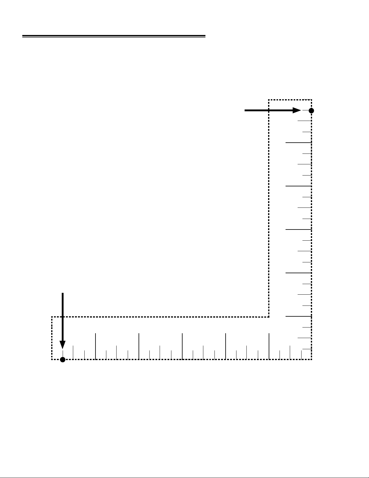
TEMPLATE FOR POST BRACKET MOUNTING
3/4"
5
3/4"
5
© 2009, The Chamberlain Group, Inc.
01-33859D All Rights Reserved
13245
13245
 Loading...