

Page 1
Bedienungsanleitung Steuerung CS 300
D
Torsteuerung CS 300 / Rev. 5.3 – 1
Page 2

2 – Torsteuerung CS 300 / Rev. 5.3
Torsteuerung CS 300 / Rev. 5.3 – 3
1. Inhaltsangabe 3. Allgemeine Sicherheitshinweise
1. Inhaltsangabe
2. Symbolerklärung 2
3. Allgemeine Sicherheitshinweise 2
4. Produktübersicht 3
5. Inbetriebnahme 5
6. Programmierung mit dem LED-Modul 8
7. Programmierung mit dem LCD-Monitor 10
8. Navigator (nur LCD-Monitor) 12
9. Funktionsübersichten 14
10. Fehleranzeige und Behebung 18
11. Technische Daten 19
12. EG-Konformitätserklärung 19
13. Anhang 20
2. Symbolerklärung
Gefahr vor Personenschäden!
Die Sicherheitshinweise sind unbedingt zu
beachten!
2
Gewährleistung
Eine Gewährleistung in Bezug auf Funktion und Sicherheit
erfolgt nur, wenn die Warn- und Sicherheitshinweise in dieser
Betriebsanleitung beachtet werden.
Für Personen- oder Sachschäden, die durch Nichtbeachtung
der Warn- und Sicherheitshinweise eintreten, haftet die
Chamberlain GmbH nicht.
Bestimmungsgemäße Verwendung
Die Steuerung CS 300 ist ausschließlich für die Steuerung von
Toranlagen mit digitalen Endlagensystemen bestimmt.
Der Betrieb ist nur in trockenen Räumen zulässig.
Zielgruppe
Nur qualizierte und geschulte Elektrofachkräfte dürfen die
Steuerung anschließen, programmieren und warten.
Qualizierte und geschulte Elektrofachkräfte erfüllen folgende
Anforderungen:
- Kenntnis der allgemeinen und speziellen Sicherheits- und
Unfallverhütungsvorschriften,
- Kenntnis der einschlägigen elektrotechnischen Vorschriften,
- Ausbildung in Gebrauch und Pege angemessener Sicherheitsausrüstung,
- Fähigkeit, Gefahren in Zusammenhang mit Elektrizität zu
erkennen.
Warnung vor Sachschäden!
Die Sicherheitshinweise sind unbedingt zu
beachten!
Information
Besondere Hinweise
ODER
Verweis auf andere Informationsquellen
Hinweise zu Montage und Anschluss
- Vor elektrischen Arbeiten muss die Anlage von der Stromversorgung getrennt werden. Während der Arbeiten muss
sichergestellt werden, dass die Stromversorgung unterbrochen bleibt.
- Die örtlichen Schutzbestimmungen sind zu beachten.
- Netz- und Steuerleitungen müssen getrennt verlegt werden.
Page 3

4. Produktübersicht D
Prüfgrundlagen und Vorschriften
Bei Anschluss, Programmierung und Wartung müssen
folgende Vorschriften beachtet werden (ohne Anspruch auf
Vollständigkeit).
Bauproduktnormen
- EN 13241-1 (Produkte ohne Feuer und Rauchschutzeigenschaften)
- EN 12445 (Nutzungssicherheit kraftbetätigter Tore -
Prüfverfahren)
- EN 12453 (Nutzungssicherheit kraftbetätigter Tore -
Anforderungen)
- EN 12978 (Schutzeinrichtungen für kraftbetätigte Tore
- Anforderungen und Prüfverfahren)
EMV
- EN 55014-1 (Störaussendung Haushaltsgeräte)
- EN 61000-3-2 (Rückwirkungen in Stromversorgungsnetzen –
Oberschwingungen)
- EN 61000-3-3 (Rückwirkungen in Stromversorgungsnetzen –
Spannungsschwankungen)
- EN 61000-6-2 (Elektromagnetische Verträglichkeit (EMV) -
Teil 6-2: Fachgrundnormen – Störfestigkeit - Industriebereich)
- EN 61000-6-3 (Elektromagnetische Verträglichkeit (EMV) -
Teil 6-3: Fachgrundnormen – Störaussendung - Wohnbereich,
Geschäfts- und Gewerbebereiche sowie Kleinbetriebe)
Maschinenrichtlinie
- EN 60204-1 (Sicherheit von Maschinen, elektrische Ausrüstung von Maschinen; Teil 1: Allgemeine Anforderungen)
- EN 12100-1 (Sicherheit von Maschinen - Grundbegriffe,
allgemeine Gestaltungsleitsätze; Teil 1: Grundsätzliche
Terminologie, Methodologie)
4.1 Varianten
Folgende Liefervarianten der Steuerung CS 300 sind möglich:
- Steuerung CS 300 mit LCD-Monitor
- Steuerung CS 300 mit LCD-Monitor im Gehäuse
- Steuerung CS 300 mit LED-Modul zur Einstellung der
Torposition AUF und Torposition ZU
(Weitere Einstellungen sind nicht möglich).
- Steuerung CS 300 ohne LED-Modul und ohne
LCD-Monitor (Modul oder Monitor werden für Einstellungen
benötigt)
Alle genannten Varianten können mit einer steckbaren
Wochenzeitschaltuhr und einem steckbarem Funkempfänger
ausgestattet werden.
Folgende Liefervarianten der Gehäuse sind möglich.
- Gehäuse mit AUF - STOP - ZU Taster
- Gehäuse mit Folientaster
- Gehäuse mit Schlüsselschalter EIN/AUS
- Gehäuse mit Hauptschalter
- Gehäuse mit Not-Aus
Die Betriebsanleitung beschreibt die Anschlussmöglichkeiten
und Programmierung der Varianten:
- Steuerung CS 300 mit LED-Platine
- Steuerung CS 300 mit aufgesteckter LCD-Display-Platine
Niederspannung
- EN 60335-1 (Sicherheit elektrischer Geräte für den Hausgebrauch und ähnliche Zwecke)
- EN 60335-2-103 (Besondere Anforderungen für Antriebe für
Tore, Türen und Fenster)
Berufsgenossenschaft D
- BGR 232 (Richtlinien für kraftbetätigte Fenster, Türen und
Tore)
Torsteuerung CS 300 / Rev. 5.3 – 3
Page 4
4. Produktübersicht
1
2
3
4
5
6
7
8
B2
B1
W
V
U
1
2
3
4
5
6
7
8
9
10
N
L3
L2
L1
X5
X4
X3
X2
X11
X7
X6
X12
PEPEPE
X1
X10
1
2
3
4
5
6
7
8
9
10
X8
X9
H4
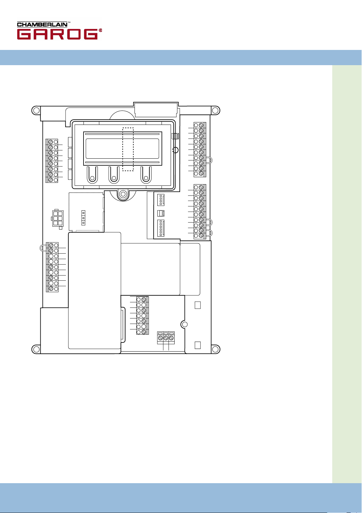
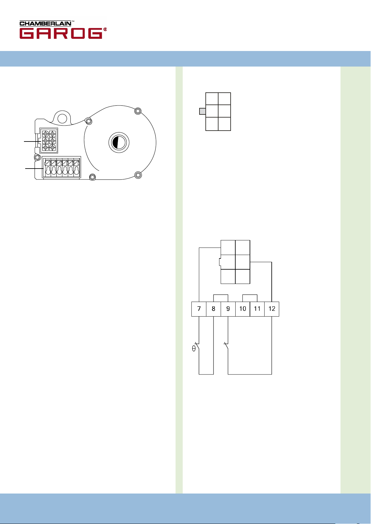
4.2 Grundplatine CS 300
(mit aufgestecktem LCD-Display-Monitor)
Erklärung:
X1: Klemmleiste Netzanschluss
X2: Klemmleiste
Motor
X3: Klemmleiste Befehlsgeräte
X4: Klemmleiste
Sicherheitselemente
X5: Klemmleiste
Relais
X6: Steckleiste für internen
EIN-AUS-Schalter
X7: Steckleiste für internen 3-
fach-Taster
X8: Stecksockel für Monitor
(Unter Monitor)
X9: Steckleiste für
Funkempfänger
X10: Steckleiste für Wochenzeit-
schaltuhr
X11: Steckleiste für digitales
Endlagensystem
X12: Steckanschluss für externen
Funkempfänger
H4: Zustandsanzeige
Schließkantensicherung (SKS)
– leuchtet bei funktionie-
render SKS
4 – Torsteuerung CS 300 / Rev. 5.3 Torsteuerung CS 300 / Rev. 5.3 – 5
Page 5
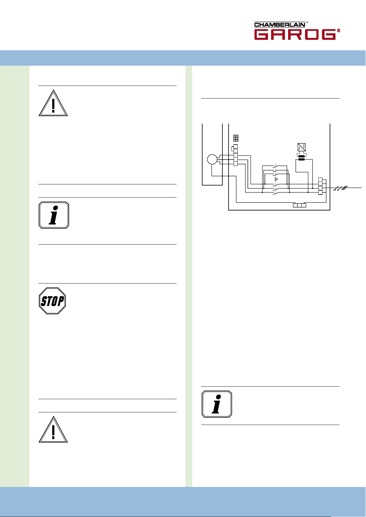
5. Inbetriebnahme
U V W B1 B2
L1 L2 L3 N
PEPEPE
1 3 5 1 3 5
2 4 6 2 4 6
400V/50Hz/3/N/PE
X2
X1
X11
T1
K2
K1
M
M1
D
5.1 Allgemeines
schließenden Komponenten wird mindestens
eine zusätzliche Isolierung mit einer Bemes-
Warnung!
sungsspannung von > 230 V empfohlen.
Um eine einwandfreie Funktion zu
gewährleisten müssen die folgenden Punkte
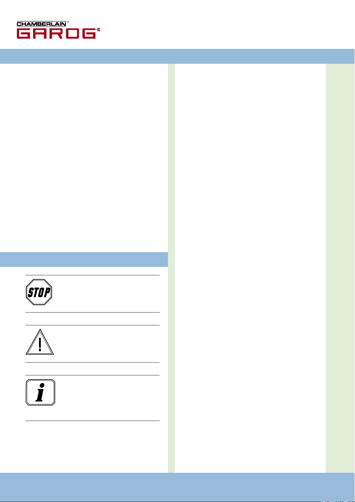
Detailschaltplan Netzanschluss und Motor
zutreffen:
- Das Tor ist montiert und funktionsfähig.
- Der Getriebemotor ist montiert und funkti-
onsbereit.
- Die Befehls- und Sicherheitsgeräte sind
montiert und funktionsbereit.
- Das Steuerungsgehäuse mit der Steuerung
CS 300 ist montiert.
Information:
Für die Montage des Tores, des
Getriebemotors und der Befehls- und Sicherheitsgeräte sind die Anleitungen der jeweiligen Hersteller zu berücksichtigen.
Erklärung:
K1: Schütz ZU
K2: Schütz AUF
M1: Motor
T1: Transformator
5.2 Netzanschluss
X1: Klemmleiste Netzanschluss
X2: Klemmleiste Motor
Gefahr!
Um die Funktion der Steuerung zu
X11: Steckleiste für digitales Endlagensystem mit
Sicherheitskreis (STOPKETTE)
gewährleisten, müssen die folgenden Punkte
zutreffen:
- Die Netzspannung muss der Angabe auf
dem Typenschild entsprechen.
- Bei Drehstrom muss ein rechtsdrehendes
Drehfeld vorliegen.
- Bei Festanschluss muss ein allpoliger Haupt
schalter verwendet werden.
-
Anschluss:
Digitales Endlagensystem an die Steuerung anschließen.
�
Steuerung an das Stromnetz anschließen.
�
Steuerung an den Motor anschließen.
�
Kabelgruppen sind unmittelbar vor der jeweiligen Klemme
�
mit einem Kabelbinder zu sichern.
- Bei Drehstromanschluss dürfen nur 3er
Blocksicherungsautomaten (10 A) verwendet
werden.
Information:
Technische Daten siehe Seite 19.
Warnung!
Vor dem erstmaligem Einschalten der Steuerung muss nach Komplettierung der Verdrahtung geprüft werden, ob alle Motoranschlüsse
steuerungs- und motorseitig festgezogen
sind. Alle Steuerspannungseingänge sind
galvanisch gegenüber der Versorgung
getrennt. Für alle an der Steuerung anzu-
Torsteuerung CS 300 / Rev. 5.3 – 5
Page 6
6 – Torsteuerung CS 300 / Rev. 5.3
Torsteuerung CS 300 / Rev. 5.3 – 7
5. Inbetriebnahme
1
2
3
4
5
6
7
8
1
2
3
4
5
6
7
8
9
10
1
2
3
4
5
6
7
8
9
10
+
-
1
2
3
4
5
6
7
8
9
10
+
-
1
2
3
4
5
6
7
8
9
10
+
-
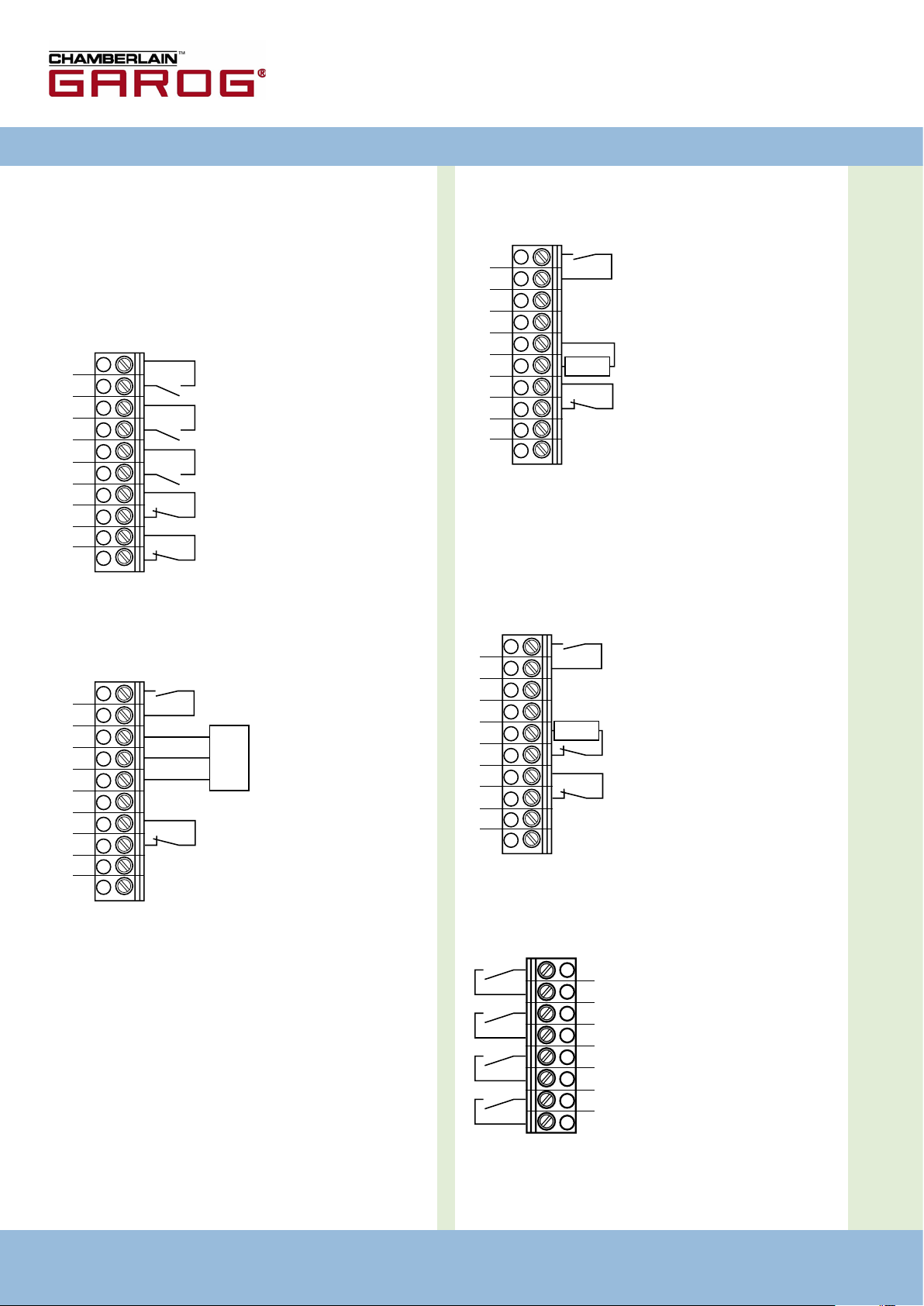
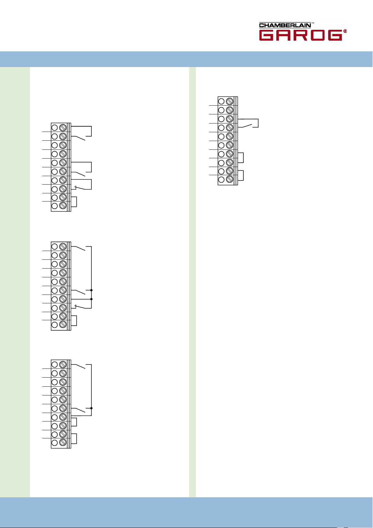
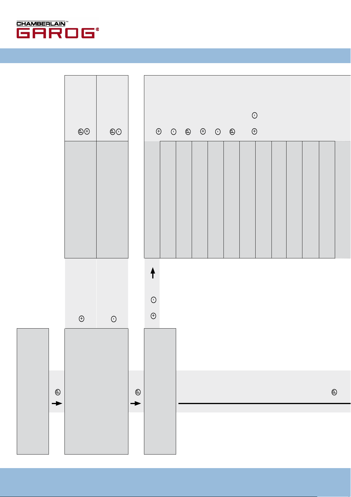
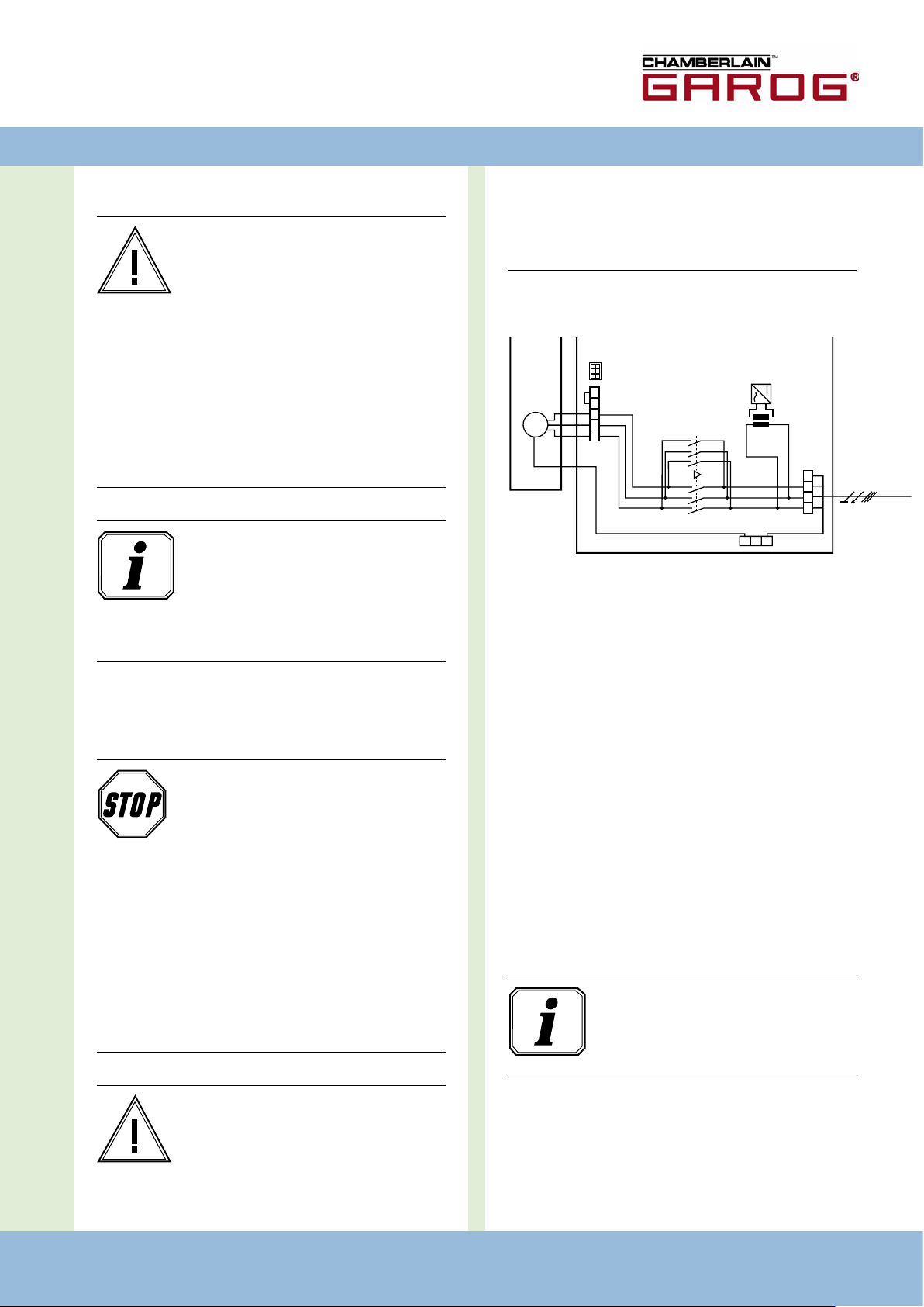
5.3 Anschlussbelegung Befehls- und
Sicherheitsgeräte
Über die Klemmen X3, X4 und X5 können vorhandene
Befehls- und Sicherheitsgeräte angeschlossen werden.
Klemmleiste X3
- Taster ZU
- Taster Impuls1
- Taster AUF
- Taster STOP
- Not Aus, Schlaffseilschalter,
Schlupftürkontakt, Einzugsicherung
Klemmleiste X4
(für opto-elektronische Schließkantensicherung)
- TEIL-AUF
2
Klemmleiste X4
( für 8,2 kOhm-Schließkantensicherung)
- TEIL-AUF
- Schließkantensicherung
8,2 KOhm
- Durchfahrt
Lichtschranke
- 24 V DC / 250 mA
Klemmleiste X4
(für pneumatische Schließkantensicherung - DW:
- Ein 8,2 KOhm-Widerstand muss in Reihe geschaltet
werden
- Der Eingabepunkt DW-TEST muss eingeschaltet werden)
- TEIL-AUF
2
3
4
2
wt
gr
br
1
Folgesteuerung
2
Taster oder Umschalter
3
wirkt in Abwärtsrichtung
4
für externe Schaltgeräte
(Anschluss an Klemme 1 und 2)
wt: weiß
gr: grün
br: braun
- Schließkantensicherung
0 V
Sig
+12 V
OPTO
- Durchfahrt
Lichtschranke
- 24 V DC / 250 mA
8,2 KOhm
3
4
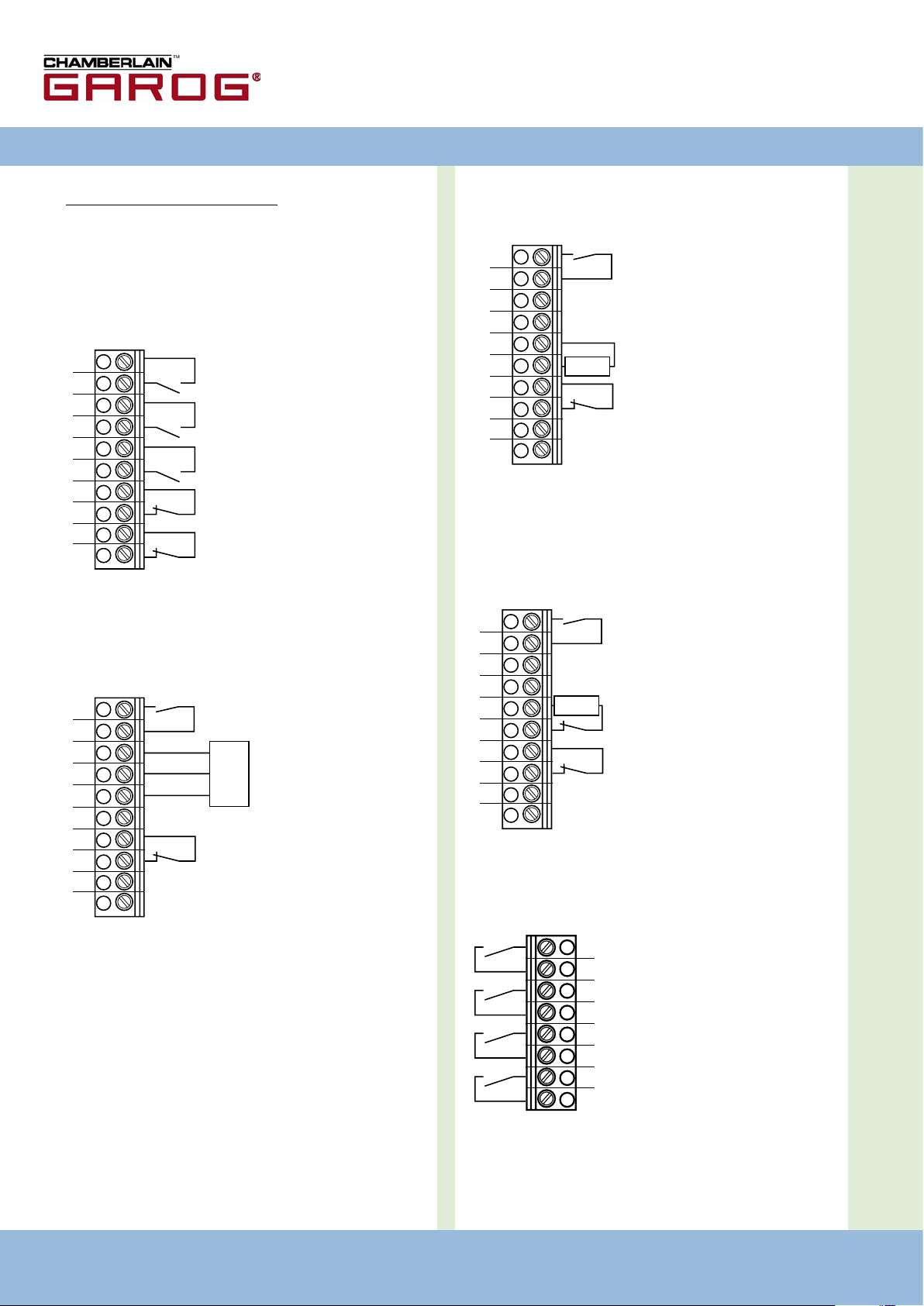
Klemmleiste X5
(potentialfreie Schaltkontakte)
- Schließkantensicherung
- Durchfahrt
Lichtschranke
- 24 V DC / 250 mA
- Relais 1
- Relais 2
- Relais 3
- Relais 4
3
4
Page 7
D
1
2
3
4
5
6
7
8
9
10
1
2
3
4
5
6
7
8
9
10
1
2
3
4
5
6
7
8
9
10
1
2
3
4
5
6
7
8
9
10
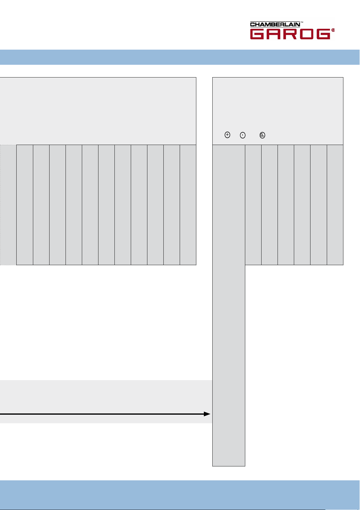
5.4 Anschlussbeispiele Befehls- und
Sicherheitsgeräte (Klemme X3)
Taster AUF / STOP / ZU
(6-Ader Lösung)
- Taster ZU
- Taster AUF
- Taster STOP
Taster AUF / STOP / ZU
(4-Ader Lösung)
- Taster ZU
Impulstaster
(Folgesteuerung)
- Taster Impuls
Anschluss:
Vorhandene Befehls- und Sicherheitsgeräte an die Steue-
�
rung anschließen.
- Taster AUF
- Taster STOP
Schlüsselschalter AUF / ZU
- ZU
- AUF
Torsteuerung CS 300 / Rev. 5.3 – 7
Page 8
8 – Torsteuerung CS 300 / Rev. 5.3
Torsteuerung CS 300 / Rev. 5.3 – 9
6. Programmierung mit dem LED-Modul
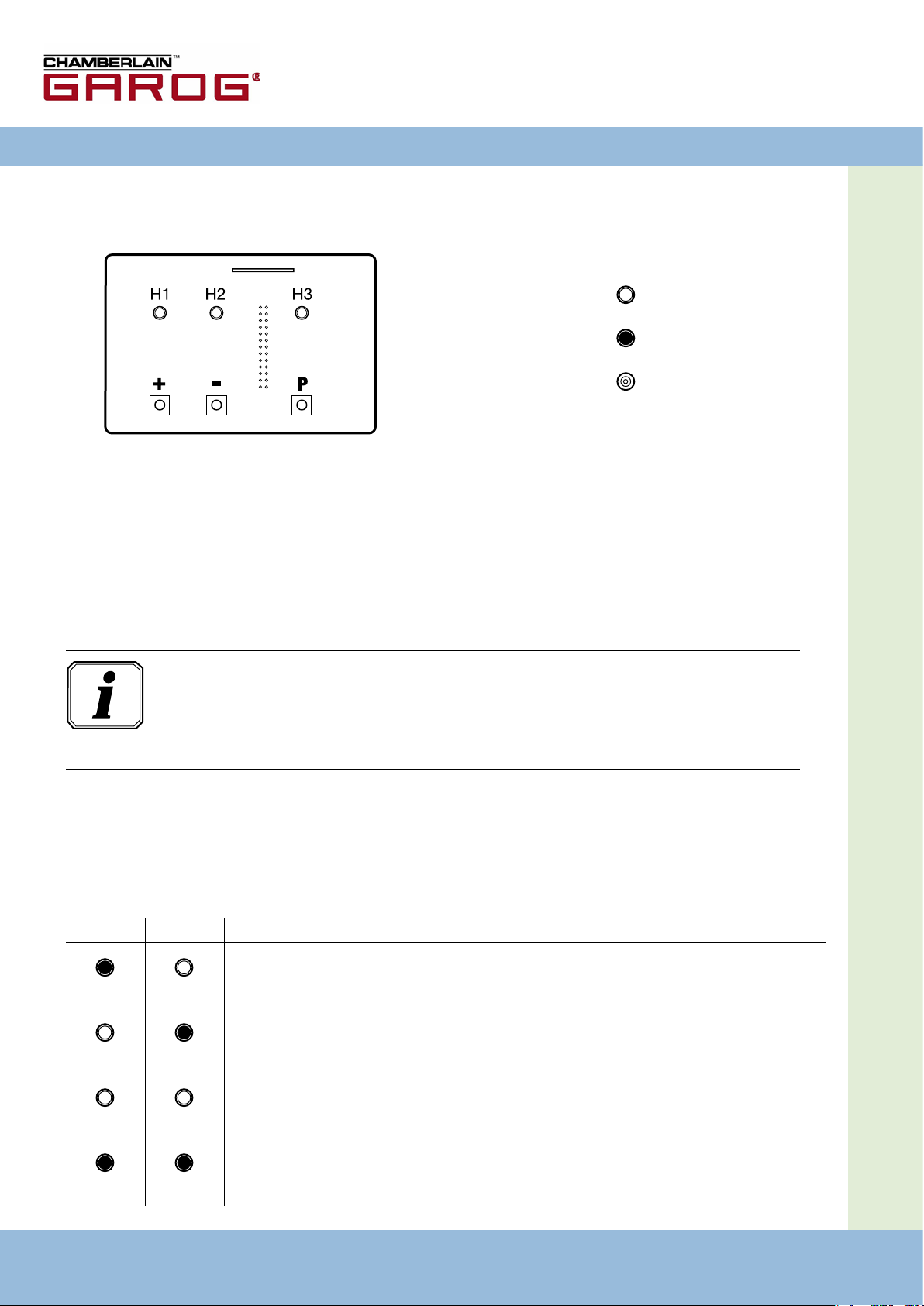
6.1 Übersicht LED-Modul
6.2 Betriebsarten des LED-Moduls
Die Steuerung verfügt mit dem LED-Modul über zwei Betriebsarten:
1. AUTOMATIK
2. JUSTIERUNG
Erklärung:
LED aus
LED leuchtet
LED blinkt
Information:
Die Betriebsart, in der sich die Steuerung bendet, wird über die LED´s angezeigt.
- In der Betriebsart AUTOMATIK blinkt keine LED.
- In der Betriebsart JUSTIERUNG blinkt mindestens eine LED.
Durch Drücken der Taste P kann zwischen den Betriebsarten gewechselt werden.
Betriebsart 1: AUTOMATIK
In der Betriebsart AUTOMATIK wird die Toranlage betrieben.
LED-Anzeigen:
H1 H2 Zustand
Das Tor ist geöffnet. Die programmierte Endlage AUF ist erreicht.
Das Tor ist geschlossen. Die programmierte Endlage ZU ist erreicht.
Das Tor steht in Zwischenstellung. Keine Endlage ist erreicht.
Das Tor ist über die Endlage ZU/AUF bewegt worden.
Page 9
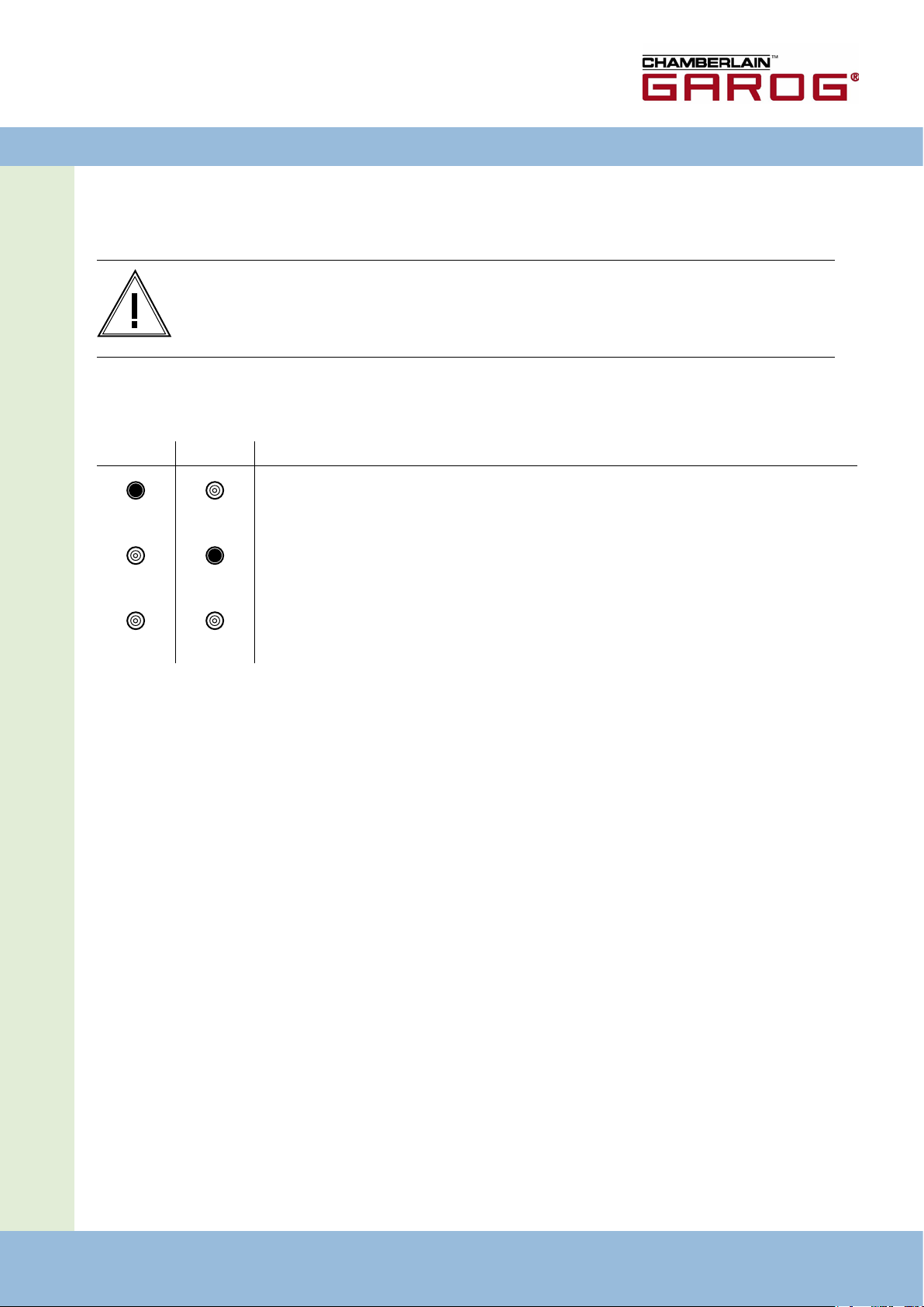
Betriebsart 2: JUSTIERUNG
In der Betriebsart JUSTIERUNG werden die Endlagen AUF/ZU eingestellt.
Warnung!
In der Betriebsart JUSTIERUNG erfolgt keine Abschaltung bei Erreichen der Endlage.
Durch Überfahren der Endlage kann das Tor beschädigt werden.
LED-Anzeigen:
H1 H2 Zustand
D
Die Endlage AUF ist in dieser Torstellung programmiert.
Die Endlage ZU ist in dieser Torstellung programmiert.
Endlage ZU und AUF sind in dieser Torstellung nicht programmiert.
6.3 Einstellen der Endlagen
Einstellen der Endlage AUF
Wechsel in die Betriebsart JUSTIERUNG durch Drücken der Taste (P).
�
Tor durch Drücken der Taste (+) in die gewünschte Endlage AUF fahren.
�
Endlage abspeichern durch Drücken der Taste (P) und zusätzliches Drücken der Taste (+).
�
Einstellen der Endlage ZU
Wechsel in die Betriebsart JUSTIERUNG durch Drücken der Taste (P).
�
Tor durch Drücken der Taste (-) in die gewünschte Endlage ZU fahren.
�
Endlage abspeichern durch Drücken der Taste (P) und zusätzliches Drücken der Taste (-).
�
Torsteuerung CS 300 / Rev. 5.3 – 9
Page 10
7. Programmierung mit dem LCD-Monitor
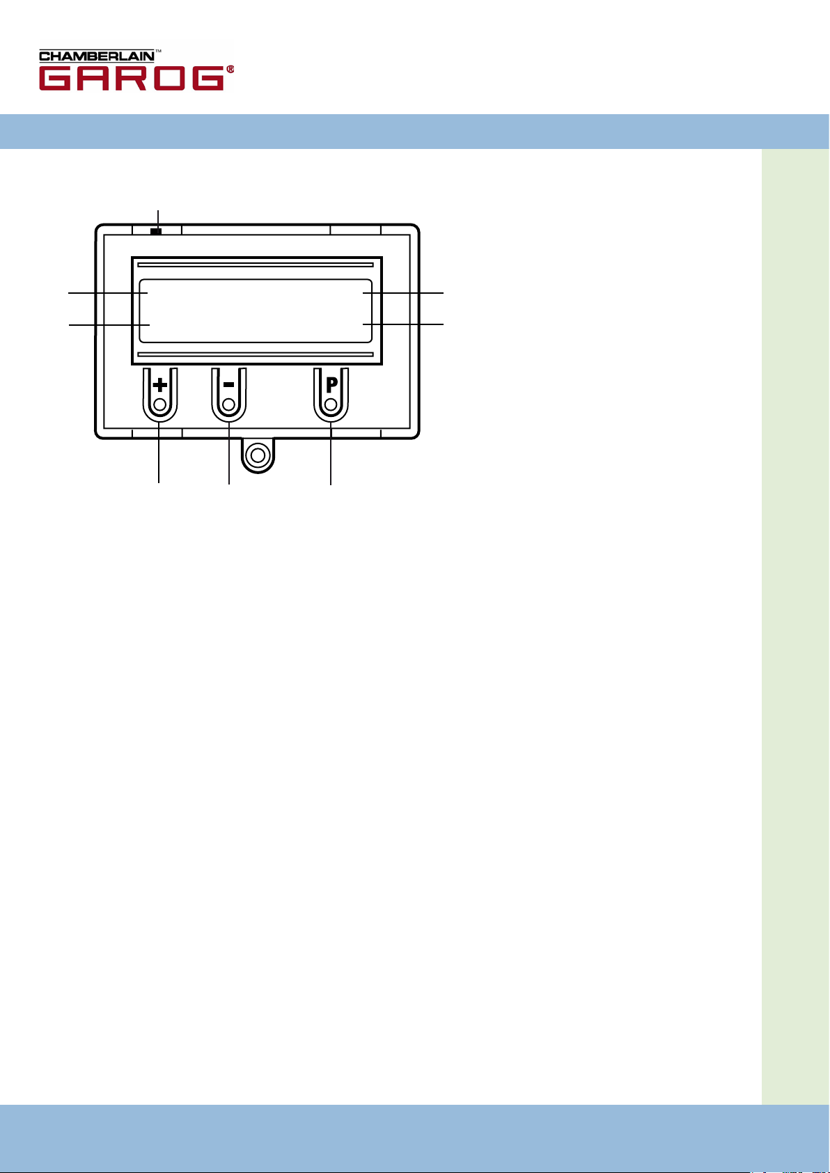
7.1 Übersicht LCD-Monitor
H
A
B
AUTOMATIK O
RUHESTELLUNG
C D E
Erklärung:
A: Betriebsart /
Diagnose Info
G
F
B: Parameter /
Diagnose Info
C: Taste (+)
D: Taste (-)
E: Taste (P)
F: Wert / Status
G: Wert / Status
H: Jumper
10 – Torsteuerung CS 300 / Rev. 5.3 Torsteuerung CS 300 / Rev. 5.3 – 11
Page 11
D
7.2 Betriebsarten des LCD-Monitors
Die Steuerung verfügt mit dem LCD-Monitor über vier
Betriebsarten:
1. AUTOMATIK
2. JUSTIERUNG
3. EINGABE
4. DIAGNOSE
Wenn der Jumper H gezogen wird, sind die
Tasten (+), (-) und (P) ohne Funktion.
Die Displayanzeige funktioniert weiterhin.
Betriebsart 1: AUTOMATIK
In der Betriebsart AUTOMATIK wird die Toranlage betrieben.
Display:
- Anzeige der durchgeführten Funktion
- Anzeige der möglichen Fehler
Betriebsart 3: EINGABE
In der Betriebsart EINGABE können die Werte verschiedener
Parameter verändert werden.
Display:
- Anzeige des ausgewählten Parameters
- Anzeige des eingestellten Wertes / Status
Betriebsart 4: DIAGNOSE
In der Betriebsart DIAGNOSE können torspezische Kontrollen
abgefragt werden.
Display:
- Anzeige der Kontrolle
- Anzeige des Kontrollstatus
Wird im Eingabemenü der Parameter „Selbsthaltung“ auf
MOD2 oder MOD3 gestellt, wechselt die Display-Anzeige von
AUTOMATIK auf HANDBETRIEB.
Betriebsart 2: JUSTIERUNG
In der Betriebsart JUSTIERUNG werden die Endlagen AUF/ZU
eingestellt.
Warnung!
In der Betriebsart JUSTIERUNG erfolgt keine
Abschaltung bei Erreichen der Endlage.
Durch Überfahren der Endlage kann das Tor
beschädigt werden.
Eine Feineinstellung kann in der Betriebsart EINGABE
erfolgen.
Display:
- Anzeige des Endlagenwertes
Torsteuerung CS 300 / Rev. 5.3 – 11
Page 12
12 – Torsteuerung CS 300 / Rev. 5.3
Torsteuerung CS 300 / Rev. 5.3 – 13
P
>1 Sek.
+
P
+
-
P
P
+
-
+
-
P
+
-
P
+
-
P
+
-
P
8. Navigator (nur LCD-Monitor)
und
> 1 Sek.
halten
Torposition speichern:
JUSTIERUNG
HAND AUF
> 1 Sek.
halten und -
Torposition speichern:
JUSTIERUNG
HAND AB
> 1 Sek.
> 2 Sek
> 2 Sek.
Menü hochblättern:
Menü runterblättern:
Wert auswählen:
EINGABE
DEUTSCH :
EINGABE
LAUFZEIT : 60
EINGABE
> 1 Sek.
OFFENZEIT : 0
Wert erhöhen:
EINGABE
VORWARNUNG : 0
Wert vermindern:
Wert speichern:
EINGABE
UMKEHRZEIT : 0,3
EINGABE
MOD1-3 RUHE : Mod1
GABE:
Zurück zur Betriebsart EIN-
EINGABE
SCHNELL-ZU : OFF
und
EINGABE
RELAIS 1 : Mod6
EINGABE
RELAIS 2 : Mod7
EINGABE
RELAIS 3 : Mod1
EINGABE
RELAIS 4 : Mod14
EINGABE
DW-TEST : OFF
AUTOMATIK
RUHESTELLUNG
> 2 Sek.
>1 Sek.
und
>1 Sek.
EINGABE
-> Position TOR AUF
JUSTIERUNG
-> Position TOR ZU
RUHESTELLUNG
Page 13
+
> 2 Sek
-
P
> 2 Sek.
Menü hochblättern:
Menü runterblättern:
AUTOMATIK:
Zurück zur Betriebsart
D
Nur Abfrage möglich
EINGABE
VERZ.-AUF : OFF
EINGABE
FEIN.-AUF : 4050
EINGABE
FEIN.-ZU : 3950
EINGABE
V.ES.-AUF : 4000
EINGABE
V. ES.-ZU : 4000
EINGABE
DREHFELD : RE
EINGABE
REVERS.-OFF : 50
EINGABE
KRAFT : 0
EINGABE
AUTO-NIVEAU : OFF
EINGABE
SELBSTHALT: : ON
EINGABE
SO/WI : MOD1
ES OBEN : ON
ES UNTEN : ON
AUF-TASTE : OFF
TEILAUF : OFF
ZU-TASTE : OFF
SKS : ON
IMPULS : OFF
SCHALTUHR : OFF
DURCHF.-LS : ON
STOPKETTE : ON
ZYKLUS : 4
AWG : 2599
DIAGNOSE
Torsteuerung CS 300 / Rev. 5.3 – 13
Page 14

14 – Torsteuerung CS 300 / Rev. 5.3
Torsteuerung CS 300 / Rev. 5.3 – 15
9. Funktionsübersichten
9.1 Betriebsart Automatik
Anzeige Beschreibung
AUTOMATIK
OEFFNEN
AUTOMATIK
SCHLIESSEN
AUTOMATIK
RUHESTELLUNG
AUTOMATIK O
RUHESTELLUNG
AUTOMATIK o
RUHESTELLUNG
AUTOMATIK U
RUHESTELLUNG
AUTOMATIK u
RUHESTELLUNG
Das Tor fährt in die Endposition AUF*
Das Tor fährt in die Endposition ZU
Das Tor steht in einer Zwischenposition
Das Tor steht in der Endposition AUF
Das Tor steht in der Position TEIL-AUF („Vor-Endlage“ oben)
Das Tor steht in der Endposition ZU
Das Tor steht in der Position TEIL-ZU („Vor-Endlage“ unten)
AUTOMATIK r
RUHESTELLUNG
*Während der Torfahrt AUF wird die zur Zeit anliegende Kraft angezeigt.
Das Tor steht in der Position der Reversierabschaltung
Page 15

9.2 Betriebsart Eingabe
D
Funktion Beschreibung
DEUTSCH Wahl der Menü-Sprache DEUTSCH
LAUFZEIT Überwachung der max. Laufzeit einer Auf- und Ab-Bewegung 1 – 250 Sekunden 60 Sekunden
OFFENZEIT Nach dem Öffnen fährt das Tor nach Ablauf des eingestellten Wertes in Richtung ZU
VORWARNZEIT
UMKEHRZEIT
MOD1-3
RUHE
Offenzeit > 0 = Impulsfunktionen nur in Richtung AUF
Die Ampel blinkt vor der Abwärtsbewegung des Tores.
Die eingestellte Vorwarnzeit ist nur aktiv bei Offenzeit > 0 oder bei Funkimpulsbetrieb
Stillstandzeit bei jeder Richtungsänderung
MOD1: im Ruhezustand AUS
MOD2: im Ruhezustand EIN
Einstellmöglichkeiten
ENGLISH
FRANCAIS
ESPANOL
NEDERLANDS
POLSKI
CESKY
ITALIANO
0 – 600 Sekunden 0 =
0 - 120 Sekunden 0 = Aus
0,1 - 2,0 Sekunden (in
1/10 Sekunden)
MOD1
MOD2
Werkseinstellung
DEUTSCH
Auto-Zufahrt Aus
0,3 Sekunden
MOD1
SCHNELL-ZU ON: Die Offenzeit wird abgebrochen nachdem die Lichtschranke durchfahren
OFF: Die Offenzeit läuft normal ab
RELAIS 1 Allen 4 Relais kann ein Relaismodus von 1 - 18 zugeordnet werden
MOD1: Rotampel während Torlaufs und blinkend in Vorwarnung
MOD2: Rotampel blinkend während Torlauf und blinkend in Vorwarnung
MOD3: Rotampel während Torlauf und in Vorwarnung
RELAIS 2 MOD1 - MOD17 MOD7
RELAIS 3 MOD1 - MOD17 MOD1
RELAIS 4 MOD1 - MOD17 MOD14
Auf diese 3 MOD wirkt der Parameter M1-3 RUHE
MOD4: Impuls bei AUF-Befehl
MOD5: Störmeldung
MOD6: Endlage AUF
MOD7: Endlage ZU
MOD8: Endlage AUF negiert
MOD9: Endlage ZU negiert
MOD10: Vor-Endlage AUF
MOD11: Vor-Endlage ZU
MOD12: Vor-Endlage ZU bis Endlage ZU
MOD13: Magnetschlossfunktion
MOD14: Bremse
MOD15: Bremse negiert
MOD16: Bremse bleibt in Offenzeit ON
MOD17: Bremse bleibt in Offenzeit und bei Richtungsumkehr ON
wurde (Anlage schließt sofort)
(bei SKS fällt Bremse ab)
ON
OFF
MOD1 - MOD17 MOD6
OFF
Torsteuerung CS 300 / Rev. 5.3 – 15
Page 16

16 – Torsteuerung CS 300 / Rev. 5.3
Torsteuerung CS 300 / Rev. 5.3 – 17
Funktion Beschreibung
DW-TEST ON: DW-Testung ist aktiv
OFF: DW-Testung ist inaktiv
Die Testung des DW-Schalters erfolgt in der Endlage ZU. Dabei muss der DW-Kontakt
beim Aufsetzen des Tores auf den Boden kurz unterbrochen werden.
Einstellmöglichkeiten
ON
OFF
Werkseinstellung
OFF
VERZ.AUF ON: Vorwarnung vor dem Öffnen
OFF: Sofortiges Öffnen
FEIN-AUF Feinjustage der Endlage AUF 0 – 8190 4050
FEIN-ZU Feinjustage der Endlage ZU 0 – 8190 3950
V.ES-AUF Einstellung des Schaltpunktes Vor-Endlage AUF (TEIL-AUF) 0 – 8190 4000
V.ES-ZU Einstellung des Schaltpunktes Vor-Endschalter ZU 0 – 8190 4000
DREHFELD RE: Rechtsdrehend
LI: Linksdrehend
Diese Einstellung darf nur bei Sondermontage des Antriebs verändert werden!
REVERS. OFF Punkt der Reversierabschaltung bevor die Endlage ZU erreicht wird 10 – 250 50
ON
OFF
RE
LI
OFF
RE
KRAFT Die Kraft wird im Display während der Auffahrt angezeigt.
AUTONIVEAU
SELBSTHALT. MOD1: Automatikbetrieb
SO/WI MOD1: Taster TEIL-AUF an Klemmleiste X4 (9 + 10)
Bei aktivierter Kraftüberwachung muss ein kleinerer Wert als der kleinste während der
Auffahrt angezeigte Wert eingestellt werden.
Je größer die Differenz zum kleinsten angezeigten Wert, desto unempndlicher
reagiert die Kraftüberwachung.
Die Kraftüberwachung ist nur aktiviert, wenn der eingestellte Wert > 0.
ON: Bodenanpassung EIN
OFF: Bodenanpassung AUS
MOD2: Handbetrieb für AUF + ZU
MOD3: Handbetrieb für ZU
MOD2: Wahlschalter TEIL-AUF an Klemmleiste X4 (9 + 10)
Wenn der Wahlschalter geschlossen ist, gehen alle AUF-Befehle in den
Vor-Endschalter AUF
0 – 999 0
ON
OFF
MOD1 - MOD3 MOD1
MOD1
MOD2
OFF
MOD1
Page 17

9.3 Betriebsart Diagnose
Anzeige Bedeutung Zustand
D
ES-AUF Endlage AUF OFF: betätigt
ES-ZU Endlage ZU OFF: betätigt
AUF-TASTE AUF-Taste ON: betätigt
TEILAUF TEIL-AUF-Taste (X4 / 9 + 10) ON: betätigt
ZU-TASTE ZU-Taste ON: betätigt
SKS Schließkantensicherung ON: System ist geschlossen
IMPULS Impuls-Taster ON: betätigt
ON: nicht betätigt
ON: nicht betätigt
OFF: nicht betätigt
OFF: nicht betätigt
OFF: nicht betätigt
OFF: System ist unterbrochen (Störung)
OFF: nicht betätigt
SCHALTUHR Wochenzeitschaltuhr ON: betätigt
DURCHF.-LS Durchfahrtlichtschranke ON: geschlossen
STOPKETTE - Stopp-Taste der Steuerung
- Stopp-Systeme des Antriebs
ZYKLUS Torzyklen-Zähler Anzeige der Torzyklen
AWG Absolutwertgeber Anzeige des Torpositionswertes
OFF: nicht betätigt
OFF: unterbrochen (Störung)
ON: geschlossen
OFF: unterbrochen (Störung)
Torsteuerung CS 300 / Rev. 5.3 – 17
Page 18

10. Fehleranzeige und Behebung
Störung / Fehlermeldung Ursache Behebung
Anlage reagiert nicht - Keine Spannung vorhanden - Spannungsversorgung von Antrieb und
Tor fährt bei Betätigung der AUF-Taste in die
Endlage ZU
Tor fährt bei Betätigung derZU-Taste in die
Endlage AUF
ERROR ENDLAGE - Das Tor steht außerhalb der Endlagen
ERROR LAUFZEIT - Die programmierte Laufzeit ist überschritten
ERROR SKS - Schließkantensicherung fehlerhaft - Schließkantensicherung und Spiralkabel
ERROR DW-TESTUNG - Der DW-Schalter löst in der Endlage ZU nicht
- Drehfeld liegt falsch an - Drehfeld überprüfen und ggf. Rechts-Drehfeld
- Die Endlagen sind noch nicht programmiert
worden
- Schließkantensicherung hat angesprochen
aus
Steuerung überprüfen
herstellen
- Programmierung der Endlagen überprüfen
und ggf. neu einstellen
- Laufweg des Tores überprüfen
- Laufzeit neu programmieren
überprüfen
- Hindernis aus Torweg entfernen
- DW-Schalter, Spiralkabel und Prol überprüfen
- Einstellung der Endlage ZU überprüfen
ERROR DREHFELD - An der Klemme X1 liegt ein falsches Drehfeld an- Sicherstellen, dass ein rechtes Drehfeld
ERROR RS 485 - Kommunikationsfehler zwischen Endschalter
und Steuerung
ERROR KRAFT - Die Kraftüberwachung hat angesprochen - Torgängigkeit überprüfen
anliegt
- Kabel- und Steckverbindung überprüfen
- Kraftwert neu einstellen
Nach Behebung der Störungsursache muss die Steuerung einmal spannungsfrei geschaltet werden!
18 – Torsteuerung CS 300 / Rev. 5.3 Torsteuerung CS 300 / Rev. 5.3 – 19
Page 19

11. Technische Daten
D
Abmessungen
Gehäuse:
Montage: senkrecht an der Wand; Mindesthöhe von
Versorgung über
L1, L2, L3, N, PE:
Absicherung: 10 A K-Charakteristik
Eigenverbrauch der
Steuerung:
Steuerspannung: 24 V DC, max. 250 mA; abgesichert durch
Steuereingänge: 24 V DC, alle Eingänge sind potentialfrei anzu-
Steuerausgänge: 24 V DC, max. 250 mA
RS485 A und B nur für elektronische Endschalter
Sicherheitskette /
Notaus:
215 x 275 x 190
100 mm
400 V, 50 / 60Hz; Aufnahmeleistung max.
2200 W - 3,2 A; Einschaltdauer 60% bei einer
Laufzeit von max. 120 s
max. 250 mA
selbstrückstellende Sicherung für externe
Sensorik
schließen. min. Signaldauer für Eingangssteuerbefehl >100 ms
RS485 Pegel, abgeschlossen mit 120 Ω
alle Eingänge unbedingt potentialfrei anschließen; bei Unterbrechung der Sicherheitskette ist
keine elektrische Bewegung des Antriebes mehr
möglich, auch nicht in Totmannschaltung
Eingang Sicherheitsleiste:
Relaisausgänge: werden induktive Lasten geschaltet (z.B. weitere
Temperaturbereich: Betrieb: -10°C ... +45°C
Luftfeuchte: bis 80% nicht kondensierend
Vibrationen: schwingungsarme Montage, z.B. an einer
Schutzart IP 54
Gewicht ca. 1,8 kg
für elektrische Sicherheitsleisten mit
8,2 kΩ Abschlusswiderstand und für
dynamische optische Systeme
Relais oder Bremsen), so müssen diese mit entsprechenden Entströmmaßnahmen (Freilaufdiode, Varistoren, RC-Glieder) ausgerüstet werden.
Arbeitskontakt potentialfrei; min. 10 mA ;
max. 230 V AC / 4A.
Einmal für Leistungsschaltung benutzte
Kontakte können keine Kleinströme mehr
schalten.
Lagerung: -25°C ... +70°C
gemauerten Wand
Torsteuerung CS 300 / Rev. 5.3 – 19
Page 20
13. Anhang
4
5
6
7
8
9
Endschalter und Sicherheitskette Antrieb
Elektrische Schnittstelle
A
B
A: AWG-Stecker
B: AWG-Steckklemme
Aderbelegung AWG-Stecker
Die Zahlen auf dem Stecker sind gleichzeitig die
Adernummern:
4: Sicherheitskette Eingang
5: RS 485 B
6: GND
7: RS485 A
8: Sicherheitskette Ausgang
9: 7...18V
AWG-Steckklemmen (7-12)
DC
C
C: Thermoelement im Antrieb
D: Nothandbetätigung (Notkurbel oder Notkette)
20 – Torsteuerung CS 300 / Rev. 5.3 Torsteuerung CS 300 / Rev. 5.3 – 21
D
Page 21

D
Torsteuerung CS 300 / Rev. 5.3 – 21
Page 22

22 – Torsteuerung CS 300 / Rev. 5.3
Torsteuerung CS 300 / Rev. 5.3 – 23
Page 23

D
Torsteuerung CS 300 / Rev. 5.3 – 23
Page 24

Page 25
Operating Instructions for Control CS 300
GB
CS 300 Gate Controls / Rev. 5.3 - 1
Page 26
2 – CS 300 Gate Controls / Rev. 5.3
CS 300 Gate Controls / Rev. 5.3 – 3
1. Contents 3. General safety instructions
1. Contents
2. Key to symbols 2
3. General safety instructions 2
4. Overview of products 3
5. Initial Operation 5
6. Programming with the LED module 8
7. Programming with the LCD monitor 10
8. Navigator (LCD monitor only) 12
9. Overview of functions 14
10. Error messages and rectication 18
11. Technical data 19
12. EU Declaration of Conformity 19
13. Appendix 20
2. Key to symbols
Danger of personal injury!
The safety instructions must be observed!
Warning! Danger to property!
The safety instructions must be observed!
2
Guarantee
The function and safety of the equipment is only guaranteed
if the warning and safety instructions included in these operating instructions are adhered to.
Chamberlain GmbH is not liable for any personal injury or
damage to property that occurs as a result of the warning and
safety instructions being disregarded.
Using the equipment for its intended purpose
The CS 300 controls are designed only for controlling gates
and doors with digital end position systems.
It is only permitted to operate the equipment in dry rooms.
Target group
Only qualied and trained electricians may connect,
programme and service the controls.
Qualied and trained electricians meet the following
requirements:
- knowledge of the general and specic safety and accident
prevention regulations,
- knowledge of the relevant electrical regulations,
- trained in the use and care of appropriate safety equipment,
- capable of recognising the dangers associated with
electricity.
Instructions for installation and connection
- The controls must be disconnected from the electricity supply before carrying out electrical works. It must be ensured
that the electricity supply remains disconnected during the
works.
- Local protective regulations must be complied with.
- Mains cables and control cables must be laid separately.
Information
Special information
OR
Reference to other sources of
information
Page 27

4. Overview of products GB
GB
Regulations and bases for testing
For connecting, programming and servicing, the following
regulations must be observed (the list is not exhaustive).
Construction product standards
- EN 13241-1 (Products without re resistance or smoke
control characteristics)
- EN 12445 (Safety in use of power operated doors -
Test methods)
- EN 12453 (Safety in use of power operated doors -
Requirements)
- EN 12978 (Safety devices for power operated doors and
gates - Requirements and test methods)
Electromagnetic compatibility
- EN 55014-1 (Radio disturbance, household appliances)
- EN 61000-3-2 (Disturbances in supply systems -
harmonic currents)
- EN 61000-3-3 (Disturbances in supply systems -
voltage uctuations)
- EN 61000-6-2 (Electromagnetic compatibility (EMC) -
Part 6-2: Generic standards - Immunity for industrial
environments)
- EN 61000-6-3 (Electromagnetic compatibility (EMC) -
Part 6-3: Generic standards - Emission standard for
residential, commercial and light-industrial environments)
Machinery guidelines
- EN 60204-1 (Safety of machinery, electrical equipment of
machines, part 1: general requirements)
- EN 12100-1 (Safety of machinery. Basic concepts, general
principles for design. Basic terminology, methodology)
4.1 Various options
The following package options are available for the CS 300
controls:
- CS 300 control with LCD monitor
- CS 300 control with LCD monitor in housing
- CS 300 control with LED module for setting the OPEN and
CLOSED door positions (further adjustment settings are not
possible)
- CS 300 control without LED module and without LCD
monitor (module or monitor are required for adjusting the
settings)
All the above options can be tted with a plug-in weekly
timer and a plug-in radio receiver.
The following options are available for the housing.
- housing with OPEN-STOP-CLOSE -button input unit
- housing with membrane keypad
- housing with key switch ON/OFF
- housing with main switch
- housing with emergency off switch
The operating instructions describe the connection possibilities and programming procedures for the different models:
- CS 300 control with LED board
- CS 300 control with attached LCD display board
Low voltage
- EN 60335-1 (Household and similar electrical appliances
- Safety)
- EN 60335-2-103 (Particular requirements for drives for
gates, doors and windows)
Professional association (D)
- BGR 232 (Directive for Power-driven Windows, Doors and
Gates)
CS 300 Gate Controls / Rev. 5.3 – 3
Page 28

4. Overview of products
1
2
3
4
5
6
7
8
B2
B1
W
V
U
1
2
3
4
5
6
7
8
9
10
N
L3
L2
L1
X5
X4
X3
X2
X11
X7
X6
X12
PEPEPE
X1
X10
1
2
3
4
5
6
7
8
9
10
X8
X9
H4
4.2 CS 300 basic board
(with attached LCD display monitor)
Key:
X1: terminal block
mains connection
X2 : terminal block
motor
X3: terminal block
command devices
X4: terminal block
safety elements
X5: terminal block
relay
X6: sockets for internal
ON-OFF switch
X7: sockets for internal
3-button input unit
X8: socket for monitor
(under monitor)
X9: sockets for
radio receiver
X10: sockets for
weekly timer
X11: sockets for digital
end-position system
X12: socket for external
radio receiver
H4: status display for
safety edge protection
(SEP) – illuminated when
SEP is working
4 – CS 300 Gate Controls / Rev. 5.3 CS 300 Gate Controls / Rev. 5.3 – 5
Page 29
5. Initial Operation
U V W B1 B2
L1 L2 L3 N
PEPEPE
1 3 5 1 3 5
2 4 6 2 4 6
400V/50Hz/3/N/PE
X2
X1
X11
T1
K2
K1
M
M1
GB
GB
5.1 General
Warning!
To guarantee that the equipment
functions properly, the following points must
be ensured:
- The gate or door is installed and ope
rational.
- The drive motor is installed and
ready for operation.
- The command and safety devices are
installed and ready for operation.
- The control housing with the CS 300
control is installed.
Information:
For the installation of the gate/door,
the drive motor and the command and safety
devices, the relevant manufacturer’s instructions are to
be adhered to.
5.2 Mains connection
Danger!
To guarantee that the controls function properly, the following points must be ensured:
- The mains voltage must correspond
to the voltage stated on the type
plate.
- For a three-phase current, a
clockwise rotating eld is required.
- For a permanent connection, an
all-pole main switch must be used.
- For a three-phase connection, only
3-way automatic circuit breakers
(10A) may be used.
are galvanically isolated from the supply.
For all components to be connected to the
controls, at least one additional isolation with
a rated voltage of > 230V is recommended.
Detailed circuit diagram for mains connection and
motor
Key:
K1: protection, CLOSE
K2: protection, OPEN
M1: motor
T1: transformer
X1: terminal block for mains connection
X2: terminal block for motor
X11: sockets for digital end position system with safety
circuit (STOP CIRCUIT)
Connection:
Connect the digital end-position system to the control.
Connect the control to the mains.
Connect the control to the motor.
Short before the corresponding screw terminals, groups of
cables should be make safe by means of straps
Information:
Technical data see page 19.
Warning!
Before switching on the controls for the rst
time, a check must be carried out after completing the wiring to ensure that all the motor
connections at the motor and at the controls
are securely xed. All control voltage inputs
CS 300 Gate Controls / Rev. 5.3 – 5
Page 30
6 – CS 300 Gate Controls / Rev. 5.3
CS 300 Gate Controls / Rev. 5.3 – 7
5. Initial Operation
1
2
3
4
5
6
7
8
1
2
3
4
5
6
7
8
9
10
1
2
3
4
5
6
7
8
9
10
+
-
1
2
3
4
5
6
7
8
9
10
+
-
1
2
3
4
5
6
7
8
9
10
+
-
5.3 Allocation of connections for command
and safety devices
Command and safety devices can be connected to terminals
X3, X4 and X5.
Terminal block X3
- CLOSE switch
- impulse switch
- OPEN switch
- STOP switch
- Emergency off, slack rope
switch, wicket door contact,
draw-in protection
Terminal block X4
(for optoelectronic safety edge protection)
1
Terminal block X4
(for 8.2 kOhm safety edge protection)
- PART - OPEN2
- safety edge protection
8,2 KOhm
- photoelectric drive-through
3
barrier
- 24 V DC / 250 mA
Terminal block X4
(for pneumatic safety edge protection – pressure sensor test:
- A 8.2 kOhm resistor must be connected in series
- The input point pressure sensor TEST must be switched on)
- PART - OPEN
4
2
wt
gr
br
1
sequence control
2
button or selector switch
3
effective in down direction
4
for external switching devices
(connection to terminals 1 and 2)
wt: white
gr: green
br: brown
- PART – OPEN
0 V
- safety edge protection
Signal
+12 V
OPTO
- photoelectric
drive-through barrier
- 24 V DC / 250 mA
2
3
4
Terminal block X5
(potential free switch contact)
8,2 KOhm
- safety edge protection
- photoelectric drive-through
3
barrier
- 24 V DC / 250 mA
- relay 1
- relay 2
- relay 3
- relay 4
4
Page 31

GB
1
2
3
4
5
6
7
8
9
10
1
2
3
4
5
6
7
8
9
10
1
2
3
4
5
6
7
8
9
10
1
2
3
4
5
6
7
8
9
10
5.4 Connection examples for command and
safety devices (terminal block X3)
OPEN / STOP / CLOSE buttons
(6-lead solution)
- CLOSE button
- OPEN button
- STOP button
OPEN / STOP / CLOSE buttons
(4-lead solution)
- CLOSE button
Impulse button
(sequence control)
- impulse button
Connection:
Connect the command and safety devices to the control.�
- OPEN button
- STOP button
Key switch OPEN / CLOSE
- CLOSE
- OPEN
CS 300 Gate Controls / Rev. 5.3 – 7
Page 32

8 – CS 300 Gate Controls / Rev. 5.3
CS 300 Gate Controls / Rev. 5.3 - 9
6. Programming with the LED module
6.1 Overview of LED module
6.2 LED module, modes of operation
With the LED module, the controls have two modes of operation:
1. AUTOMATIC
2. ADJUSTMENT
Key:
LED off
LED illuminated
LED ashing
Information:
The current mode of operation of the control is shown via the LEDs.
- In the AUTOMATIC mode, no LEDs ash.
- In the ADJUSTMENT mode, at least one LED ashes.
Pressing the P button toggles between the modes of operation.
Operating mode 1: AUTOMATIC
In the AUTOMATIC operating mode the door system is operated.
LED displays:
H1 H2 Status
The door is open. The programmed OPEN end position has been reached.
The door is closed. The programmed CLOSED end position has been reached.
The door is between end positions. No end position has been reached.
The door has been moved beyond the CLOSED/OPEN end position.
Page 33

Operating mode 2: ADJUSTMENT
In the ADJUSTMENT mode, the OPEN/CLOSED end position settings are adjusted.
Warning!
In the ADJUSTMENT mode of operation, the drive does not switch off when the end position is reached. The door
can be damaged if driven beyond the end position.
LED displays:
H1 H2 Status
GB
The OPEN end position is programmed at this door position.
The CLOSED end position is programmed at this door position.
The CLOSED and OPEN end positions are not programmed at this door position.
6.3 Setting the end positions
Setting the OPEN end position
Change the mode of operation to ADJUSTMENT by pressing the (P) button.
Drive the door into the desired OPEN end position by pressing the (+) button.
Save the end position by pressing simultaneously the (P) button and the (+) button.
Setting the CLOSED end position
Change the mode of operation to ADJUSTMENT by pressing the (P) button.
Drive the door into the desired CLOSED end position by pressing the (-) button.
Save the end position by pressing simultaneously the (P) button and the (-) button.
CS 300 Gate Controls / Rev. 5.3 - 9
Page 34

7. Programming with the LCD monitor
7.1 Overview of the LCD monitor
H
A
B
AUTOMATIC O
RESTING
C D E
Key:
A: mode of operation /
G
F
diagnostic info
B: parameter /
diagnostic info
C: (+) button
D: (-) button
E: (P) button
F: value / status
G: value / status
H: jumper
10 – CS 300 Gate Controls / Rev. 5.3 CS 300 Gate Controls / Rev. 5.3 – 11
Page 35

GB
7.2 LCD monitor, modes of operation
The control has four modes of operation with the LCD monitor:
1. AUTOMATIC
2. ADJUSTMENT
3. INPUT
4. DIAGNOSIS
When the jumper H is pulled, the (+) button, the (-) button
and the (P) button have no function.
The display still functions.
Operating mode 1: AUTOMATIC
In the AUTOMATIC operating mode the door system is
operated.
Display:
- displays the function being carried out
- displays any error messages
Operating mode 3: INPUT
In the INPUT operating mode, the values of various parameters
can be altered.
Display:
- displays the selected parameter
- displays the programmed value /status
Operating mode 4: DIAGNOSIS
In the DIAGNOSIS operating mode, door-specic checks can
be queried.
Display
- displays the check
- displays the checking status
If the “self locking“ parameter is set to MOD2 or MOD3 in
the input menu, the display changes from AUTOMATIC to
MANUAL OPERATION.
Operating mode 2: ADJUSTMENT
In the ADJUSTMENT mode, the OPEN/CLOSED end position
settings are adjusted.
Warning!
In the ADJUSTMENT mode of operation, the
drive does not switch off when the end position is reached.
The door can be damaged if driven beyond
the end position.
Fine adjustments can be made in the INPUT operating mode.
Display:
- displays the end position value
CS 300 Gate Controls / Rev. 5.3 – 11
Page 36

12 – CS 300 Gate Controls / Rev. 5.3
CS 300 Gate Controls / Rev. 5.3 - 13
P
>1 Sec.
+
P
+
-
P
-
P
+
-
+
-
P
+
-
P
+
-
P
+
-
P
8. Navigator (LCD monitor only)
> 1 Sec.
> 1 Sec.
Hold P pressed and
Save door position:
MANUAL
ADJUSTMENT OPEN
> 1 Sec.
Hold P pressed and
Save door position:
MANUAL
ADJUSTMENT DOWN
> 2 Sek
> 2 Sec.
Scroll up through menu:
Scroll down through menu:
Select value:
INPUT
GERMAN :
> 2 Sec.
INPUT
INPUT
RUNNING TIME : 60
> 1 Sec.
TIME OPEN : 0
Increase value:
INPUT
Decrease value:
Save value:
FOREWARNING : 0
INPUT TURN-
AROUND TIME : 0,3
INPUT
MOD1-3 RESTING : Mod1
Return to
INPUT:
INPUT
QUICK CLOSE : OFF
and
INPUT
RELAY 1 : Mod6
INPUT
RELAY 2 : Mod7
INPUT
RELAY 3 : Mod1
INPUT
RELAY 4 : Mod14
INPUT Pressure
sensor TEST : OFF
AUTOMATIC
RESTING
-> Position DOOR
OPEN
ADJUSTMENT
RESTING
-> Position DOOR CLOSED
>1 Sec.
and
>1 Sec.
INPUT
Page 37

GB
+
-
P
INPUT
DELAY-OPEN : OFF
INPUT
FINE-OPEN : 4050
INPUT
FINE-CLOSE : 3950
INPUT
BES-OPEN : 4000
INPUT
BES-CLOSE : 4000
INPUT
> 2 Sek
> 2 Sec.
Scroll up through menu:
Scroll down through menu:
ROT. FIELD : RE
INPUT
REVERSE OFF : 50
INPUT
POWER : 0
INPUT
AUTO LEVEL : OFF
INPUT
SELF LOCK : ON
INPUT
SU/WI : MOD1
Return to AUTOMATIC
operating mode:
ES UP : ON
ES DOWN : ON
OPEN BUTTON : OFF
PART OPEN : OFF
Only query is possible
CLOSE BUTTON : OFF
SEP : ON
IMPULS : OFF
TIMER : OFF
P/E BARRIER : ON
STOP CIRCUIT : ON
CYCLE : 4
AVE : 2599
DIAGNOSIS
CS 300 Gate Controls / Rev. 5.3 - 13
Page 38

14 – CS 300 Gate Controls / Rev. 5.3
CS 300 Gate Controls / Rev. 5.3 - 15
9. Overview of functions
9.1 Automatic operating mode
Display Description
AUTOMATIC
OPEN
AUTOMATIC
CLOSE
AUTOMATIC
RESTING
AUTOMATIC O
RESTING
AUTOMATIC o
RESTING
AUTOMATIC U
RESTING
AUTOMATIC u
RESTING
The door is driven to the OPEN* end position
The door is driven to the CLOSED* end position
The door stands between the end positions
The door stands at the OPEN end position
The door stands at the position PART OPEN („before-end position“ up)
The door stands at the CLOSED end position
The door stands at the position PART CLOSE („before-end position“ down)
AUTOMATIC r
RESTING
*When the gate is being driven OPEN, the power currently being used is displayed
The door stands in the position where the reversing switches off
Page 39

9.2 Input operating mode
Function Description Setting options Factory setting
GB
DEUTSCH Select the menu language DEUTSCH
RUNNING
TIME
OPEN
TIME
ADVANCE
WARNING
TIME
TURNAROUND
TIME
MOD1-3
RESTING
Monitoring the max. running time for an open and close movement 1 – 250 Seconds 60 Seconds
After the door has opened, it runs in the CLOSE direction again after the set time has
elapsed.
Open time > 0 = impulse functions only work in OPEN direction
The trafc light ashes before the door starts to move downwards.
The programmed forewarning time is only active if the open time > 0 or if in radioimpulse operating mode
Standing time at every change of direction 0,1 - 2,0 Seconds (in
MOD1: in non-operative state OFF
MOD2: in non-operative state ON
ENGLISH
FRANCAIS
ESPANOL
NEDERLANDS
POLSKI
CESKY
ITALIANO
0 – 600 Seconds 0 =
0 - 120 Seconds 0 = Off
1/10 Sec)
MOD1
MOD2
DEUTSCH
Auto-close off
0,3 Seconds
MOD1
QUICK
CLOSE
RELAY 1 All 4 relays can be allocated to a relais mode of 1-18
RELAY 2 MOD1 - MOD17 MOD7
RELAY 3 MOD1 - MOD17 MOD1
RELAY 4 MOD1 - MOD17 MOD14
ON: The open time is cut short after the photoelectric barrier has been passed
(door closes immediately)
OFF: The open time continues as usual
MOD1: Red lights while the gate moves and ashing in prewarning mode
MOD2: Red lights are ashing while the gate moves and ashing in prewarning
MOD3: Red lights while the gate moves and in prewarning
The parameter M1-3 non-operative state takes effect at these 3 MOD
MOD4: Impulse at OPEN order
MOD5: Error message
MOD6: OPEN end position
MOD7: CLOSE end position
MOD8: Final position OPEN denied
MOD9: Final position CLOSED denied
MOD10: Before-end position OPEN
MOD11: Before-end position CLOSE
MOD12: From before CLOSE position to CLOSE position
MOD13: Magnetic locking function
MOD14: Brake
MOD15: Brake negated
MOD16: Brake remains ON during open time
MOD17: Brake remains ON in open time and while changing direction
(in SKS, brake falls down)
ON
OFF
MOD1 - MOD17 MOD6
OFF
CS 300 Gate Controls / Rev. 5.3 - 15
Page 40

16 – CS 300 Gate Controls / Rev. 5.3
CS 300 Gate Controls / Rev. 5.3 - 17
Function Description Setting options Factory setting
Pressure
sensor TEST
DELAY-OPEN ON: Forewarning before opening
FINE-OPEN Fine adjustment of OPEN end position 0 – 8190 4050
FINE-CLOSE Fine adjustment of CLOSE end position 0 – 8190 3950
BES-OPEN Setting the before-end position switch point for the OPEN direction (PART-OPEN) 0 – 8190 4000
BES-CLOSE Setting the before-end position switch point for the CLOSE direction 0 – 8190 4000
ROT. FIELD C: clockwise rotating eld
ON: PS testing is active
OFF: PS testing is inactive
The testing of the PS switch takes place in the CLOSE end position. For this, the PS
contact must be temporarily broken when the gate lowers to rest on the ground.
OFF: Immediate opening
A: anti-clockwise rotating eld
ON
OFF
ON
OFF
C
A
OFF
OFF
C
This setting may only be altered in the case of a special customised drive installation!
REVERSE
OFF
POWER The power is displayed during the opening movement.
AUTOLEVEL
SELF LOCK. MOD1: Automatic operation
SU/WI MOD1: PART-OPEN button at terminal X4 (9 + 10)
The point where the reversing switch is activated before the CLOSE end position is
reached.
If the power monitoring facility is activated, a value must be set, which is lower than
the lowest value displayed during opening. The larger the difference, in comparison to
the lowest value displayed, the less sensitive the reaction of the power monitoring.
The power monitoring facility is only activated if the value is set to be > 0.
ON: Align with ground, ON
OFF: Align with ground, OFF
MOD2: Manual operation for OPEN and CLOSE
MOD3: Manual operation for CLOSE
MOD2: PART-OPEN selector switch at terminal X4 (9 + 10)
When the selector switch is closed, all OPEN commands go to the before-
end switch OPEN
10 – 250 50
0 – 999 0
ON
OFF
MOD1 - MOD3 MOD1
MOD1
MOD2
OFF
MOD1
Page 41

9.3 Diagnostic operating mode
Display Meaning Status
GB
ES-OPEN OPEN end position OFF: conrmed
ES-CLOSE CLOSE end position OFF: conrmed
OPEN BUTTON OPEN button ON: conrmed
PART OPEN PART OPEN button (X4 / 9 + 10) ON: conrmed
CLOSE BUTTON CLOSE button ON: conrmed
SEP Safety edge protection ON: system circuit is closed
IMPULSE Impulse button ON: conrmed
ON: not conrmed
ON: not conrmed
OFF: not conrmed
OFF: not conrmed
OFF: not conrmed
OFF: system is interrupted (fault)
OFF: not conrmed
TIMER Weekly timer ON: conrmed
P/E BARRIER Photoelectric drive-through barrier ON: circuit closed
STOP CIRCUIT - Stop button of controls
- Stop systems of drive
CYCLE Gate-cycle counter Displays the gate cycles
AVE Absolute value encoder Shows the gate position value
OFF: not conrmed
OFF: interrupted (fault)
ON: circuit closed
OFF: interrupted (fault)
CS 300 Gate Controls / Rev. 5.3 - 17
Page 42

10. Errormessagesandrectication
Fault / error message Cause Rectication
System does not respond - No voltage supply - Check the voltage supply of the drive and the
Door travels to the CLOSE end position when
the OPEN button is pressed
Door travels to the OPEN end position when
the CLOSE button is pressed
ERROR END POSITION - The door has travelled beyond one of the end
ERROR RUN TIME - The programmed running time has been
ERROR SEP - The safety edge protection is faulty - Check the safety edge protection and the
ERROR PRESSURE SENSOR TESTING - The PS switch is not activated at the CLOSE
- Rotating eld is connected wrongly - Check the rotating eld and establish clock-
positions
- The end positions have not been programmed
yet
exceeded
- Safety edge protection was triggered - Remove obstruction from path of door
end position
controls
wise rotating eld if necessary
- Check the programming of the end positions
and reset them if necessary
- Check the path of the door
- Re-programme the running time
spiral cable
- Check the PS switch, spiral cable and prole
- Check the setting for the CLOSE end position
ERROR ROT. FIELD - An incorrect rotating eld is connected to
terminal X1
ERROR RS 485 - Communications fault between the end
position switch and the controls
ERROR POWER - The power monitoring has been triggered - Check that the door can move freely
- Ensure that a clockwise rotating eld is
connected
- Check the cable and socket connections
- Reset the power value
Afterrectifyingthecauseofthefault,thecontrolsmustbedisconnectedbrieyfromthemains!
18 – CS 300 Gate Controls / Rev. 5.3 CS 300 Gate Controls / Rev. 5.3 – 19
Page 43

11. Technical data
GB
Dimensions of
housing:
Assembling height: vertically at the wall, min. at a height of
Power supply via
L1, L2, L3, N, PE:
Protection: 10 A K-characteristic
Own consumption of
control:
Control voltage: 24 V DC, max. 250 mA; protected by self-reset-
Control inputs: 24 V DC, all inputs are to be connected free of
Control outputs: 24 V DC, max. 250 mA
RS485 A and B Only for electronic nal switch.
Safety chain /
Emergency
shutdown:
215 x 275 x 190
100 mm
400 V, 50 / 60 Hz; - max. power input 2200 W
- 3.2 A; duty cycle 60% for a maximum run-
ning time of 120 s
max. 250 mA
ting safety for external sensors
potential, min. signal time for incoming control
command >100 ms.
RS485 level, closed with 120 Ω
all input connections must be potential-free;
if the safety circuit is interrupted, no further
electrically powered movement of the drive is
possible,
not even in deadman mode.
Input safety bar: For electrical safety bars with 8,2 kΩ, moving
Relays output: If inductive loads are switched to (e.g.: relays
Temperature range: Operation: -10 °C ... +45 °C
Air humidity: to 80% non condensing
Vibrations: Assembling works with less vibration, e.g. at a
Type of protection: IP 54
Weight: about 1,8 kg
loads and dynamic optic systems.
or breaks), so these must be equipped with
corresponding interference measures (recovery
diode, varistores, RC modules).
Operating contact free of potential,
min. 10 mA; max. 230V AC / 4A
Contacts used once for power switch are not
able to switch mini power anymore.
Storage: -25 °C ... +70 °C
masonned wall
CS 300 Gate Controls / Rev. 5.3 – 19
Page 44

20 – CS 300 Gate Controls / Rev. 5.3
CS 300 Gate Controls / Rev. 5.3 – 21
13. Appendix
4
5
6
7
8
9
Limit switch and safety circuit for drive
Electronic interface
A
B
A: AVE plug (absolute value encoder plug)
B: AVE plug terminal (absolute value encoder plug termi-
nal)
Wiring allocation,
AVE (absolute value encoder) plug
The numbers on the plug are also the wire-numbers.
4: Safety circuit input
5: RS 485 B
6: GND
7: RS485 A
8: Safety circuit output
9: 7...18V
AVE (absolute value encoder) plug terminal (7-12)
DC
C
C: Thermal element in the drive
D: Manual emergency control
(emergency crank or emergency chain)
D
Page 45

GB
CS 300 Gate Controls / Rev. 5.3 – 21
Page 46

22 – CS 300 Gate Controls / Rev. 5.3
CS 300 Gate Controls / Rev. 5.3 – 23
Page 47

GB
CS 300 Gate Controls / Rev. 5.3 – 23
Page 48

Page 49

Instructions de service Commande CS 300
F
Instructions de service Commande CS 300 / Rev. 5.3 – 1
Page 50

2 – Instructions de service Commande CS 300 / Rev. 5.3
Instructions de service Commande CS 300 / Rev. 5.3 – 3
1. Sommaire 3. Consignes générales de sécurité
1. Sommaire
2. Explication des symboles 2
3. Consignes générales de sécurité 2
4. Présentation du produit 3
5. Mise en service 5
6. Programmation par le module à diodes lumineuses 8
7. Programmation par l‘écran à cristaux liquides 10
8. Navigateur (uniquement avec l‘écran LCD) 12
9. Présentation des fonctions 14
10. Afchage des pannes et remèdes 18
11. Caractéristiques techniques 19
12. Déclaration de conformité CE 19
13. Annexe 20
2. Explication des symboles
Risque de dommage corporel !
Il est impératif de respecter les consignes de
sécurité !
2
Garantie
Une garantie concernant la fonctionnalité et la sécurité d‘uti
lisation entrera en vigueur uniquement si les consignes et les
avertissements de sécurité contenus dans ces instructions de
service ont été respectés.
La société Chamberlain GmbH ne se portera pas responsable
des dommages corporels ou matériels dus à un non respect des
consignes et des avertissements de sécurité.
Application conforme
La commande CS 300 a été exclusivement conçue pour piloter
les installations de portes équipées de systèmes numériques de
ns de course.
La mise en service est uniquement autorisée dans les pièces
sèches.
Groupe cible
Seul du personnel qualié et formé sera autorisé à brancher, programmer et prendre en charge la maintenance de la commande.
Un personnel qualié et formé est un personnel sufsamment
instruit et disposant des qualications suivantes, correspondant à
leur activité :
- Connaissance des règles générales et spéciques de sécurité et
de prévention d‘accidents,
- Connaissances des règles se rapportant à l‘électrotechnique,
- Formation concernant l‘utilisation et l‘entretien d‘un équipe
ment de sécurité adapté,
- Capacité de reconnaître les dangers liés à l‘électricité.
-
-
Risque de dommage matériel !
Il est impératif de respecter les consignes de
sécurité !
Information
Consignes particulières
OU
Référence vers d‘autres sources d‘information
Consignes se rapportant au montage et au branchement
- Avant tous travaux électriques, l‘installation doit absolument
être mise hors tension. Pendant les travaux, l‘alimentation
électrique doit impérativement restée coupée.
- Respecter les normes locales en vigueur.
- Pour éviter les phénomènes d‘induction, il est impératif de
séparer dans des gaines différentes les câbles d‘asservissement
des câbles d‘alimentation du moteur.
Page 51

4. Présentation du produit F
Bases des contrôles et règlements
Lors du branchement, de la programmation et de la maintenance,
il est impératif de respecter les règles suivantes (intégralité non
garantie).
Normes produits
- EN 13241-1 (Produits sans propriétés de protection contre le
feu et la fumée)
- EN 12 445 (Sécurité à l‘utilisation des portes motorisées
- Procédure de contrôle)
- EN 12 453 (Sécurité à l‘utilisation des portes motorisées
- Exigences)
- EN 12978 (Dispositifs de protection pour les portes motorisées Exigences et procédure de contrôle)
EMV
- EN 55014-1
(Compatibilité électromagnétique - Exigences pour les appareils
électrodomestiques)
- EN 61000-3-2 (Limites pour les émissions de courant
harmonique)
- EN 61000-3-3 (Immunité aux creux et variations de tension)
- EN 61000-6-2 (Compatibilité électromagnétique (CEM) Partie 6-2 : Normes génériques - Immunité pour les environnements industriels)
- EN 61000-6-3 (Compatibilité électromagnétique (CEM) - Partie
6-3 : Normes génériques - Norme sur l‘émission pour les envi-
ronnements résidentiels, commerciaux et de l‘industrie légère)
4.1 Alternatives
Les alternatives suivantes de la commande CS 300 sont
disponibles :
- Commande CS 300 avec écran LCD
- Commande CS 300 avec écran LCD dans le boîtier
- Commande CS 300 avec un module à diodes lumineuses pour
le réglages des positions de porte OUVERTURE et FERMETURE
(des réglages supplémentaires ne sont pas possibles).
- Commande CS 300 sans module à diodes lumineuses et sans
écran LCD (pour effectuer les réglages, un écran ou un module
est indispensable)
Toutes les alternatives citées peuvent être équipées d‘une
minuterie hebdomadaire et d‘un récepteur radio enchable.
Les alternatives suivantes de boîtier sont disponibles :
- Boîtier avec des touches MONTEE-STOP-DESCENTE
- Boîtier avec bouton à efeurement
- Boîtier avec contacteur à clé MARCHE/ARRET
- Boîtier avec interrupteur principal
- Boîtier avec arrêt d‘urgence
Les instructions de service décrivent les possibilités de
branchement et de programmation des alternatives :
- Commande CS 300 avec platine à diodes lumineuses
- Commande CS 300 avec platine à écran LCD enché
Directive machines
- EN 60204-1 (Sûreté de fonctionnement des machines, de leurs
équipements électriques, Partie 1 : Règles générales)
- EN 12100-1 (Sécurité des machines - Notions fondamentales,
principes généraux de conception - Partie 1 : Terminologie de
base, méthodologie)
Basse tension
- EN 60335 - 1 (sécurité des appareils électriques destinés à un
usage domestique ou autre usage du même genre)
- EN 60335-2-103 (Règles particulières pour les motorisations de
portails, portes et fenêtres)
Caisse professionnelle d‘assurance accidents D
- BGR 232 (règles directives pour les fenêtres et portes
motorisées)
Instructions de service Commande CS 300 / Rev. 5.3 – 3
Page 52

4. Présentation du produit
1
2
3
4
5
6
7
8
B2
B1
W
V
U
1
2
3
4
5
6
7
8
9
10
N
L3
L2
L1
X5
X4
X3
X2
X11
X7
X6
X12
PEPEPE
X1
X10
1
2
3
4
5
6
7
8
9
10
X8
X9
H4
4.2 Platine de base CS 300
(avec écran LCD enché)
Explication :
X1 : Barrette
Branchement sur secteur
X2 : Barrette Moteur
X3 : barrette
Eléments de commande
X4 : Barrette
Eléments de sécurité
X5 : Barrette
Relais
X6 : Connecteur pour le
commutateur interne
MARCHE-ARRET
X6 : Connecteur pour le bouton
triple interne
X8 : Socle à ches pour l‘écran
(Sous écran)
X9 : Connecteur pour le récepteur
radio
X10 : Connecteur pour la minuterie
hebdomadaire
X11 : Connecteur pour le système
numérique de ns de course
X12 : Prise de courant embrochable
pour récepteur radio externe
H4 : Indicateur de l‘état de la bar-
re palpeuse (SKS) – s‘allume
si la barre fonctionne
4 – Instructions de service Commande CS 300 / Rev. 5.3 Instructions de service Commande CS 300 / Rev. 5.3 – 5
Page 53

5. Mise en service
U V W B1 B2
L1 L2 L3 N
PEPEPE
1 3 5 1 3 5
2 4 6 2 4 6
400V/50Hz/3/N/PE
X2
X1
X11
T1
K2
K1
M
M1
F
5.1 Généralités
Avertissement !
Pour assurer un fonctionnement sans problèmes, les points suivants doivent être appliqués
:
- La porte est montée et fonctionnelle.
- Le moto-réducteur est monté et fonctionnel.
- Les auxiliaires de commande et de sécurité
sont montés et fonctionnels.
- Le boîtier de la commande et la commande
CS 300 sont montés.
Information :
Il faut absolument respecter les instructions du fa
bricant correspondant, lors du montage de la porte,
du moto-réducteur et des auxiliaires de commande
et de sécurité.
5.2 Branchement sur secteur
Danger !
Pour assurer le fonctionnement de la
commande, les points suivants doivent être
appliqués :
- La tension du secteur doit correspondre aux
indications de la plaquette signalétique.
- En présence de courant triphasé, il doit y
avoir un champs magnétique tournant à
droite.
- En présence d‘un branchement xe, il faut
utiliser un interrupteur principal tous pôles.
- En présence de branchement à courant
triphasé, seule l‘utilisation de trois blocs
de coupe-circuits automatiques (10A) est
autorisée.
l’alimentation. Pour tous les composants devant
être raccordés sur le dispositif de commande, nous
conseillons au minimum une isolation supplémentaire avec une tension assignée supérieure à 230 V.
Plan détaillé des connexions secteur et moteur
-
Explication :
K1 : Contacteur FERME
K1 : Contacteur OUVERT
M1 : Moteur
T1 : Transformateur
X1 : Barrette branchement secteur
X2 : Barrette moteur
X11 : Connecteur pour le système numérique de ns de
course avec circuit de sécurité (CHAINE D‘ARRET)
Branchement :
Brancher le système numérique de ns de course à la
�
commande.
Brancher la commande au secteur.
�
Brancher la commande au moteur.
�
Juste devant les bornes correspondantes, assurer les
�
groupes de câbles avec une bande pour câble.
Information :
Caractéristiques techniques voir
page 19.
Avertissement !
Avant la première mise en marche du dispositif de
commande, il convient de contrôler si, après avoir
complété le câblage, tous les raccordements du
moteur sont bien xés aussi bien côté moteur que
côté commande. Toutes les entrées de la tension
de commande sont séparées galvaniquement de
Instructions de service Commande CS 300 / Rev. 5.3 – 5
Page 54

6 – Instructions de service Commande CS 300 / Rev. 5.3
Instructions de service Commande CS 300 / Rev. 5.3 – 7
5. Mise en service
1
2
3
4
5
6
7
8
1
2
3
4
5
6
7
8
9
10
1
2
3
4
5
6
7
8
9
10
+
-
1
2
3
4
5
6
7
8
9
10
+
-
1
2
3
4
5
6
7
8
9
10
+
-
5.3 Attribution des branchements, auxiliaires de commande et de sécurité
Les auxiliaires de commande et de sécurité présents peuvent
être branchés aux barrettes X3, X4 et X5.
Barrette X3
- Bouton FERMER
- Bouton Impulsion
- Bouton OUVRIR
- Bouton STOP
- Arrêt d‘urgence, rupteur électrique anti-mou de câble, contact
portillon, sécurité anti-relevage
Barrette X4
(pour barre palpeuse opto-électronique)
- PARTIELLEMENT OU-
wt
gr
br
0 V
Sig
+12 V
VERT²
- Barre palpeuse OPTO
Barrette X4
(pour barre palpeuse 8,2 kOhm)
- PARTIELLEMENT OUVERT²
- Barre palpeuse
8,2 KOhm
- Cellule photoélectrique de
passage³
- 24V DC / 250 mA4
Barrette X4
(pour barre palpeuse pneumatique - onde de choc :
- Une résistance de 8,2 KOhm doit être commutée en série
- Le point de saisie TEST ONDE DE CHOC doit être activé)
- PARTIELLEMENT OUVERT²
8,2 KOhm
- Barre palpeuse
- Cellule photoélectrique de
passage³
- Cellule photoélectrique
de passage³
- 24V DC / 250 mA4
1
Contrôle séquentiel
2
Bouton ou commutateur
3
agit lors du mouvement de descente
4
pour les appareils externes de distribution
(Branchement aux bornes 1 et 2)
wt : blanc
gr : vert
br : marron
- 24V DC / 250 mA4
Barrette X5
(Contacts de commutation libres de potentiel (sans tension))
- Relais 1
- Relais 2
- Relais 3
- Relais 4
Page 55

F
1
2
3
4
5
6
7
8
9
10
1
2
3
4
5
6
7
8
9
10
1
2
3
4
5
6
7
8
9
10
1
2
3
4
5
6
7
8
9
10
5.4 Exemples de branchements, auxiliaires de
commande et de sécurité (barrette X3)
Bouton OUVRIR / STOP / FERMER
(solution à six ls)
- Bouton FERMER
- Bouton OUVRIR
- Bouton STOP
Bouton OUVRIR / STOP / FERMER
(solution à quatre ls)
- Bouton FERMER
Bouton à impulsion
(Contrôle séquentiel)
- Bouton impulsion
Branchement :
Brancher les auxiliaires de commande et de sécurité pré-
�
sents à la commande.
- Bouton OUVRIR
- Bouton STOP
Contacteur à clé OUVRIR / FERMER
- FERMER
- OUVRIR
Instructions de service Commande CS 300 / Rev. 5.3 – 7
Page 56

8 – Instructions de service Commande CS 300 / Rev. 5.3
Instructions de service Commande CS 300 / Rev. 5.3 – 9
6. Programmation par le module à diodes lumineuses
6.1 Présentation du module à diodes lumineuses
6.2 Types de fonctionnement du module à diodes
Avec le module à diodes, la commande dispose de deux types de service :
1. AUTOMATIQUE
2. AJUSTAGE
Explication :
Diode éteinte
Diode allumée
Diode clignote
Information :
Les diodes indiqueront le type de service dans lequel se trouve la commande.
- En service AUTOMATIQUE, aucune diode ne clignote.
- En service AJUSTAGE, au minimum une diode clignote.
Un appui sur le bouton P permet de changer de type de service.
Type de service 1 : AUTOMATIQUE
La porte sera fonctionnelle en service AUTOMATIQUE.
Afchage des diodes lumineuses :
H1 H2 Etat
La porte est ouverte. La n de course programmée d‘OUVERTURE est atteinte.
La porte est fermée. La n de course programmée de FERMETURE est atteinte.
La porte se trouve en position intermédiaire. Aucune n de course n‘est atteinte.
La porte a été déplacée en passant par les n de course FERMETURE / OUVERTURE.
Page 57

Type de service 2 : AJUSTAGE
Les ns de course OUVERTURE / FERMETURE seront réglées en service AJUSTAGE.
Avertissement !
En service AJUSTAGE, il n‘y a pas de déconnexion quand les ns de course sont atteintes.
Un dépassement des ns de course peut endommager la porte.
Afchage des diodes lumineuses :
H1 H2 Etat
F
Dans cette position de porte, la n de course OUVERTURE est programmée.
Dans cette position de porte, la n de course FERMETURE est programmée.
Dans cette position de porte, les ns de course FERMETURE et OUVERTURE ne sont pas
programmées.
6.3 Réglage des ns de course
Réglage de la n de course OUVERTURE
Passez au type de service AJUSTAGE par un appui sur le bouton (P).
�
Amener la porte en n de course OUVERTURE souhaitée en appuyant sur le bouton (+).
�
Enregistrer les ns de course en appuyant sur le bouton (P) et simultanément, sur le bouton (+).
�
Réglage de la n de course FERMETURE
Passez au type de service AJUSTAGE par un appui sur le bouton (P).
�
Amener la porte en n de course FERMETURE souhaitée en appuyant sur le bouton (-).
�
Enregistrer les ns de course en appuyant sur le bouton (P) et simultanément, sur le bouton (-).
�
Instructions de service Commande CS 300 / Rev. 5.3 – 9
Page 58

7. Programmation par l‘écran à cristaux liquides
7.1 Présentation de l‘écran à cristaux liquides
H
A
B
AUTOMATIQUE O
REPOS
C D E
G
F
Explication :
A : Type de service /
Diagnostic info
B : Paramètre /
Diagnostic info
C : Bouton (+)
D : Bouton (-)
E : Bouton (P)
F : Valeur / statut
G : Valeur / statut
H : Cavalier
10 – Instructions de service Commande CS 300 / Rev. 5.3 Instructions de service Commande CS 300 / Rev. 5.3 – 11
Page 59

F
7.2 Types de service de l‘écran à cristaux
liquides
Avec l‘écran à cristaux liquides, la commande dispose de
quatre types de service :
1. AUTOMATIQUE
2. AJUSTAGE
3. SAISIE
4. DIAGNOSTIC
Si le cavalier H est retiré, les boutons (+), (-) et (P) sont sans
fonction.
L‘afchage écran reste fonctionnel.
Type de service 1 : AUTOMATIQUE
La porte sera fonctionnelle en service AUTOMATIQUE.
Ecran :
- Afchage de la fonction en cours
- Afchage de la panne éventuelle
Type de service 3 : SAISIE
En service de SAISIE, les valeurs de différents paramètres
peuvent être modiées.
Ecran :
- Afchage du paramètre sélectionné
- Afchage de la valeur réglée / Statut
Type de service 4 : DIAGNOSTIC
En service de DIAGNOSTIC, il est possible de consulter les
contrôles spéciques à la porte.
Ecran :
- Afchage des contrôles
- Afchage du statut de contrôle
Si en menu de saisie, le paramètre « Auto-maintien » est
placé sur MOD2 ou MOD3, l‘afchage écran passe du service
AUTOMATIQUE au service MANUEL.
Type de service 2 : AJUSTAGE
Les ns de course OUVERTURE / FERMETURE seront réglées
en service AJUSTAGE.
Avertissement !
En service AJUSTAGE, il n‘y a pas de déconne-
xion quand les ns de course sont atteintes.
Un dépassement des ns de course peut
endommager la porte.
En service de SAISIE, il est possible d‘effectuer un ajustage
précis.
Ecran :
- Afchage de la valeur de n de course
Instructions de service Commande CS 300 / Rev. 5.3 – 11
Page 60

12 – Instructions de service Commande CS 300 / Rev. 5.3
Instructions de service Commande CS 300 / Rev. 5.3 – 13
P
>1 S
+
P
+
-
P
-
P
+
-
+
-
P
+
-
P
+
-
P
+
-
P
8. Navigateur (uniquement avec l‘écran LCD)
la
P et
> 1 S
Maintenir un appui sur
Mémoriser la position de
porte :
AJUSTAGE
LEVAGE MANUEL
la
P et
> 1 S
Maintenir un appui sur
Mémoriser la position de
porte :
AJUSTAGE
DESCENTE MANUELLE
> 1 S
> 2 S
Faire déler le menu en avant :
SAISIE
ALLEMAND :
> 2 S
Faire déler le menu en
arrière :
Sélectionner une valeur :
SAISIE DUREE
SAISIE DUREE
D‘OUVERTURE : 0
DU MOUVEMENT : 60
> 1 S
SAISIE
Augmenter la valeur :
AVERTISSEMENT : 0
Diminuer la valeur :
Enregistrer la valeur :
SAISIE TEMPS
D‘INVERSION : 0,3
SAISIE
MOD1-3 REPOS : Mod1
et
Retour vers le type de service
SAISIE :
SAISIE FERMET
URE RAPIDE : OFF
SAISIE
RELAIS 1 : Mod6
SAISIE
RELAIS 2 : Mod7
SAISIE
RELAIS 3 : Mod1
SAISIE
RELAIS 4 : Mod14
SAISIE TEST
ONDE DE CHOC : OFF
AUTOMATIQUE
REPOS
> 2 S
et
-> Position PORTE OUVERTE
AJUSTAGE
REPOS
-> Position PORTE FERMEE
>1 S
SAISIE
>1 S
Page 61

F
+
-
P
SAISIE OUVERTURE
RETARDEE : OFF
> 2 S
Faire déler le menu en avant :
SAISIE AJUSTAGE
OUVERTURE : 4050
SAISIE AJUSTAGE
FERMETURE : 3950
SAISIE DISPOSITIF PRE-FIN
DE COURSE OUVERTURE : 4000
SAISIE DISPOSITIF PRE-FIN
SAISIE CHAMPS
MAGNETIQUE ROTATIF : RE
SAISIE MOUVEMENT
INVERSE OFF : 50
SAISIE
FORCE : 0
SAISIE
AUTO-NIVEAU : OFF
SAISIE
AUTO-MAINTIEN : ON
SAISIE
DE COURSE FERMETURE : 4000
ETE/ HIVER : MOD1
> 2 S
Faire déler le menu en
arrière :
AUTOMATIQUE :
Retour vers le type de service
ON
: ON
INTERRUPTEUR FIN DE COURSE EN HAUT :
INTERRUPTEUR FIN DE COURSE EN BAS
Seule une consultation est
possible
: OFF
BOUTON OUVERTURE
OUVERTURE PARTIELLE : OFF
BOUTON FERMETURE : OFF
BARRE PALPEUSE : ON
IMPULSION : OFF
MINUTERIE : OFF
CELLULE PHOTO DE PASSAGE : ON
CHAINE D‘ARRET : ON
: 2599
ENCODEUR DE LA VALEUR ABSOLUE (AWG)
CYCLE : 4
DIAGNOSTIC
Instructions de service Commande CS 300 / Rev. 5.3 – 13
Page 62

14 – Instructions de service Commande CS 300 / Rev. 5.3
Instructions de service Commande CS 300 / Rev. 5.3 – 15
9. Présentation des fonctions
9.1 Type de service Automatique
Afchage Description
AUTOMATIQUE
OUVRIR
AUTOMATIQUE
FERMER
AUTOMATIQUE
REPOS
AUTOMATIQUE O
REPOS
AUTOMATIQUE o
REPOS
AUTOMATIQUE F
REPOS
AUTOMATIQUE f
REPOS
La porte se déplace en n de course OUVERTURE*
La porte se déplace en n de course FERMETURE
La porte se trouve en position intermédiaire
La porte est en n de course OUVERTURE
La porte est en position OUVERTURE PARTIELLE (« n de course primaire » en haut)
La porte est en n de course FERMETURE
La porte est en position FERMETURE PARTIELLE (« n de course primaire » en bas)
AUTOMATIQUE r
REPOS
*Lors du déplacement de la porte en OUVERTURE, la force actuelle appliquée sera afchée.
La porte est en position de déconnexion d‘inversion du mouvement
Page 63

9.2 Type de service Saisie
F
Fonction Description
DEUTSCH Sélection du langage DEUTSCH
DUREE DU
MOUVEMENT
DUREE
D‘OUVERTURE
TEMPS
D‘AVERTISSEMENT
DUREE
D‘INVERSION
MOD1-3
REPOS
Contrôle de la durée maximale d‘un mouvement d‘ouverture et de fermeture 1 – 250 Secondes 60 Secondes
Après l‘ouverture, la porte se déplace en fermeture après écoulement des valeurs
réglées
Durée d‘ouverture > 0 = fonctions impulsions uniquement dans le sens
d‘OUVERTURE
Le feu clignote avant le mouvement de descente de la porte.
Le temps d‘avertissement réglé est actif uniquement si la durée d‘ouverture > 0 ou si
le service à impulsion radio est activé
Durée du repos à chaque changement de direction 0,1 - 2,0 Secondes
MOD1 : au repos ETEINT
MOD2 : au repos ALLUME
Réglages
possibles
ENGLISH
FRANCAIS
ESPANOL
NEDERLANDS
POLSKI
CESKY
ITALIANO
0 – 600 Secondes 0 =
0 - 120 Secondes 0 = Eteint
(in 1/10 Secondes)
MOD1
MOD2
Réglage d‘usine
DEUTSCH
Fermeture
automatique Eteint
0,3 Secondes
MOD1
FERMETURE
RAPIDE
RELAIS 1 Tous les 4 relais peuvent être alloués à un mode à relais de 1-18
RELAIS 2 MOD1-MOD17 MOD7
RELAIS 3 MOD1-MOD17 MOD1
RELAIS 4 MOD1-MOD17 MOD14
ON : La durée d‘ouverture sera interrompue après un passage par la cellule
photoélectrique (l‘installation ferme immédiatement).
OFF : La durée d‘ouverture se déroule normalement
MOD1 : Feux rouge quand le portail bouge et clignotant en préavertissement
MOD2 : Feux rouge clignotant quand le portail bouge et clignotant en
préavertissement
MOD3 : Feux rouge quand le portail bouge et en préavertissement
Le paramètre M1-3 REPOS prend effet sur ces MOD3
MOD4 : Impulsion en ordre MONTEE
MOD5 : Signal de panne
MOD6 : Fin de course OUVERTURE
MOD7 : Fin de course FERMETURE
MOD8 : La n de course OUVERTURE nie
MOD9 : La n de course FERMETURE nie
MOD10 : Fin de course primaire OUVERTURE
MOD11 : Fin de course primaire FERMETURE
MOD12 : Fin de course primaire FERMETURE jusqu‘en n de course FERMETURE
MOD13 : Fonction verrou magnétique
MOD14 : Frein
MOD15 : Frein inverse
MOD16 : Pendant la durée d‘ouverture, le frein reste ON
MOD17 : Le frein reste ON quand le portail est ouvert et en cas de changement de
direction (pour barre palpeuse, le frein ne compte pas)
ON
OFF
MOD1-MOD17 MOD6
OFF
Instructions de service Commande CS 300 / Rev. 5.3 – 15
Page 64

16 – Instructions de service Commande CS 300 / Rev. 5.3
Instructions de service Commande CS 300 / Rev. 5.3 – 17
Fonction Description
TEST ONDE
DE CHOC
ON : Test onde de choc actif
OFF : Test onde de choc inactif
Le test du commutateur onde de choc se fait en n de course FERMETURE. Le contact
onde de choc doit alors être brièvement interrompu dès que la porte entre en contact
avec le sol.
Réglages
possibles
ON
OFF
Réglage d‘usine
OFF
OUVERTURE
RETARDEE
AJUSTAGE
OUVERTURE
AJUSTAGE
FERMETURE
DISPOSITIF
PRE-FIN
DE COURSE
OUVERTURE
DISPOSITIF PREFIN DE COURSE
FERMETURE
CHAMPS
MAGNETIQUE
ROTATIF
INVERS.
OFF
ON : Avertissement avant l‘ouverture
OFF : Ouverture immédiate
Ajustage de la n de course OUVERTURE 0 – 8190 4050
Ajustage de la n de course FERMETURE 0 – 8190 3950
Réglage du point de commutation avant la n de course OUVERTURE (OUVERTURE
PARTIELLE)
Réglage du point de commutation de interrupteur n de course avant FERMETURE 0 – 8190 4000
RE : Rotation à droite
LI : Rotation à gauche
Ce réglage pourra uniquement être modié en cas de montage spécial de la motorisation !
Point de déconnexion du mouvement inversé avant atteinte de la n de course
FERMETURE
ON
OFF
0 – 8190 4000
RE
LI
10 – 250 50
OFF
RE
FORCE Pendant le mouvement d‘ouverture, la force sera afchée sur l‘écran.
Si le contrôle de la force est activée, il faut régler une valeur inférieure à la plus petite
valeur afchée lors du mouvement d‘ouverture.
Plus la différence avec la plus petite valeur afchée est grande, moins sensiblement
réagira le contrôle de la force.
Le contrôle de la puissance est uniquement activé si la valeur réglée est > 0.
AUTONIVEAU
AUTOMAINTIEN
ETE/ HIVER MOD1 : Bouton OUVERTURE PARTIELLE à la barrette X4 (9 + 10)
ON : Ajustage au sol ALLUME
OFF : Ajustage au sol ETEINT
MOD1 : opération automatique
MOD2 : opération manuelle pour OUVERT + FERME
MOD3 : opération manuelle pour FERME Service automatique
MOD2 : Commutateur de sélection OUVERTURE PARTIELLE à la barrette X4
(9 + 10)
Si le commutateur de sélection est fermé, tous les ordres d‘OUVERTURE vont vers
l‘interrupteur n de course avant OUVERTURE.
0 – 999 0
ON
OFF
MOD1 - MOD3 MOD1
MOD1
MOD2
OFF
MOD1
Page 65

9.3 Type de service DIAGNOSTIC
Afchage Signication Etat
F
INTERRUPTEUR FIN
DE COURSE OUVERTURE
INTERRUPTEUR FIN
DE COURSE FERMETURE
BOUTON OUVERTURE
OUVERTURE PARTIELLE
BOUTON FERMETURE
Barre palpeuse Barre palpeuse ON : le système est fermé
IMPULSION Bouton impulsion ON : activé
Fin de course OUVERTURE OFF : activé
Fin de course FERMETURE OFF : activé
Bouton OUVERTURE ON : activé
Bouton OUVERTURE PARTIELLE (X4 /
9 + 10)
Bouton FERMETURE ON : activé
ON : non activé
ON : non activé
OFF : non activé
ON : activé
OFF : non activé
OFF : non activé
OFF : le système est interrompu (panne)
OFF : non activé
MINUTERIE Minuterie hebdomadaire ON : activé
CELLULE PHOTO DE
PASSAGE
CHAINE D‘ARRET - Bouton d‘arrêt de la commande
CYCLE Compteur du nombre de cycles de la
AWG Encodeur de la valeur absolue Afchage de la valeur de la position de la porte
Cellule photoélectrique de passage ON : fermé
- Système d‘arrêt de la motorisation
porte
OFF : non activé
OFF : interrompu (panne)
ON : fermé
OFF : interrompu (panne)
Afchage des cycles de la porte
Instructions de service Commande CS 300 / Rev. 5.3 – 17
Page 66

10. Afchage des pannes et remèdes
Panne / signal de panne Cause Remède
L‘installation ne réagit pas - Absence de tension - Vérier l‘alimentation électrique de la motori-
Après appui sur le bouton d‘OUVERTURE, la
porte se déplace en n de course FERMETURE
Après appui sur le bouton de FERMETURE, la
porte se déplace en n de course OUVERTURE
ERROR FIN DE COURSE - La porte se trouve en dehors des ns de
ERROR DUREE DU MOUVEMENT - Dépassement de la durée programmée du
ERROR BARRE PALPEUSE - La barre palpeuse ne fonctionne pas
ERROR TEST ONDE DE CHOC - En n de course FERMETURE, le commutateur
ERROR CHAMPS MAGNETIQUE ROTATIF - Un champ magnétique rotatif incorrect est
- Application incorrecte du champ magnétique
rotatif
course
- Les ns de course ne sont pas encore
programmées
mouvement
correctement
- La barre palpeuse s‘est déclenché - Supprimer l‘obstacle se trouvant dans la
DW ne se déclenche pas
appliqué à la barrette X1
sation et de la commande
- Vérier le champ magnétique rotatif et créer
un champ magnétique de rotation à droite le
cas échéant
- Vérier la programmation des ns de course
et effectuer un nouveau réglage le cas
échéant
- Vérier le trajet de la porte
- Reprogrammer la durée du mouvement
- Contrôler la barre palpeuse et le câble spiralé
trajectoire de la porte
- Contrôler le commutateur DW, le câble spiralé
et le prol
- Contrôler le réglage de la n de course
FERMETURE
- Vérier si un champ magnétique de rotation à
droite est appliqué
ERROR RS 485 - Erreur de communication entre l‘interrupteur
n de course et la commande
ERROR FORCE - Le contrôle de la force s‘est déclenché - Vérier la facilité de la porte à bouger
- Contrôler les branchements de câbles et de
ches
- Régler à nouveau la valeur de la force
Après avoir éliminé la cause de la panne, il faut commuter la commande une fois hors tension !
18 – Instructions de service Commande CS 300 / Rev. 5.3 Instructions de service Commande CS 300 / Rev. 5.3 – 19
Page 67

11. Caractéristiques techniques
Dimensions du boîtier : 215 x 275 x 190
F
Hauteur de montage : verticalement au mur, au min. à une hauteur de
Alimentation par
L1, L2, L3, N, PE :
Protection : 10A K-charactéristique
Propre consommation du
contrôle :
Tension de commande : 24 V DC, max. 250 mA; protégée par la protection de
Entrées de commande:
Sorties de commande :
RS485 A et B Seulement pour interrupteur n de course
Chaîne de sécurité /
arrêt d’urgence :
100 mm
400 V, 50 / 60 Hz; puissance consommée
max. 2200 W - 3,2 A ; durée de mise en circuit 60%
pour une durée de mouvement max. de 120 s
max. 250 mA
semi-conducteurs remettant à zéro automatique pour
les sondes externes
24 V DC, toutes les entrées sont à brancher
libre de potentiel, min. durée de signal pour entrée
d’instruction de commande >100 ms
24 V DC, max. 250 mA
électronique. RS485 niveau, fermé avec 120 Ω
Toutes les entrées sont absolument à brancher libres
de potentiel ; si la chaîne de sécurité est interrompue,
un mouvement électrique de la commande n’est plus
possible, non plus en mode de service homme-mort
Entrée de sécurité : Pour réglettes de sécurité électriques avec
Sorties de relais : Si des charges inductives sont branchées
Gamme de température : Opération : -10°C ... +45°C
Humidité : à 80% non-condensant
Vibrations : Montage peu vibrant, par ex. : à un mur maçonné
Genre de protection : IP 54
Poids : Environ 1,8 Kg
8,2 kΩ, résistance terminale et pour systèmes
optiques dynamiques
(par ex : d’autres relais et freins), elles doivent être
équipées de mesures antiparasites correspondants
(diodes à roues libres, varistances, montage RC).
Contact de fermeture libre de potentiel;
min. 10 mA ; max. 230 V AC / 4A.
Les contacts une fois prisent pour circuit de puissance
ne peuvent plus brancher des mini courants
Stockage : -25°C ... +70°C
Instructions de service Commande CS 300 / Rev. 5.3 – 19
Page 68

20 – Instructions de service Commande CS 300 / Rev. 5.3
Instructions de service Commande CS 300 / Rev. 5.3 – 21
13. Annexe
4
5
6
7
8
9
Interrupteur de n de course et chaîne de
sécurité motorisation
Jonction d‘interface électrique
A
B
A : Prise de courant EVA
(Encodeur de la valeur absolue)
B : Borne à che EVA
(Encodeur de la valeur absolue)
Occupation des ls prise de courant EVA
(Encodeur de la valeur absolue)
Les chiffres sur la prise de courant sont aussi les numéros des
ls.
4 : Chaîne de sécurité Entrée
5 : RS 485 B
6 : GND
7 : RS485 A
8 : Chaîne de sécurité sortie
9 : 7...18V
Bornes à che EVA (Encodeur de la valeur absolue)
(7-12)
DC
C
C : Thermo-élément dans la motorisation
D : Commande manuelle de secours (manivelle de
secours or chaîne de secours)
D
Page 69

F
Instructions de service Commande CS 300 / Rev. 5.3 – 21
Page 70

22 – Instructions de service Commande CS 300 / Rev. 5.3
Instructions de service Commande CS 300 / Rev. 5.3 – 23
Page 71

F
Instructions de service Commande CS 300 / Rev. 5.3 – 23
Page 72

Page 73

Gebruiksaanwijzing CS 300-besturing
NL
Deurbesturing CS 300 / Rev. 5.5 – 1
Page 74

2 – Deurbesturing CS 300 / Rev. 5.5
Deurbesturing CS 300 / Rev. 5.5 – 3
1. Inhoudsopgave 3. Algemene veiligheidsinstructies
1. Inhoudsopgave
2. Verklaring van de symbolen 2
3. Algemene veiligheidsinstructies 2
4. Productoverzicht 3
5. Ingebruikname 5
6. Programmering met de LED-module 9
7. Programmering met de LCD-monitor 11
8. Navigator (alleen LCD-monitor) 12
9. Functieoverzichten 14
10. Foutmelding en ophefng storing 22
11. Technische gegevens 23
12. Bijlage 24
2. Verklaring van de symbolen
Kans op letsel!
De veiligheidsinstructies altijd opvolgen!
2
Garantie
De garantie op goede werking en veiligheid geldt alleen
wanneer de waarschuwingen en veiligheidsinstructies in deze
gebruiksaanwijzing worden opgevolgd.
Voor persoonlijk letsel en materiële schade voortvloeiende
uit het niet opvolgen van deze waarschuwingen en
veiligheidsinstructies aanvaardt Chamberlain GmbH geen
verantwoordelijkheid.
Juist gebruik
De CS 300-besturing is alleen bestemd voor het besturen van
deuren met digitale eindpositiesystemen.
Doelgroep
Alleen gekwaliceerde en gediplomeerde elektromonteurs
mogen de besturing aansluiten, programmeren en
onderhouden.
Gekwaliceerde en geschoolde elektromonteurs voldoen aan
de volgende eisen:
- ze bezitten kennis van de algemene en speciale veiligheidsen ongevallen preventievoorschriften,
- ze bezitten kennis van de van toepassing zijnde
elektrotechnische voorschriften,
- ze hebben een opleiding gehad in het gebruik en het
onderhoud van de juiste veiligheidsuitrusting,
- ze zijn in staat om gevaren in samenhang met
elektriciteit te onderkennen.
Kans op materiële schade!
De veiligheidsinstructies altijd opvolgen!
Informatie
Bijzondere aanwijzingen
OD
Verwijzing naar andere informatiebronnen
Instructies bij montage en aansluiting
- Voorafgaande aan werkzaamheden aan de elektrische
installatie moet deze van de stroomvoorziening worden
losgekoppeld. Tijdens de werkzaamheden moet worden
gezorgd dat de stroomvoorziening ook voortdurend
onderbroken blijft.
- De plaatselijke veiligheidsbepalingen moeten worden
opgevolgd.
Page 75

4. Productoverzicht
NL
Keuringsprincipes en voorschriften
Bij aansluiting, programmering en onderhoud moeten de
volgende voorschriften in acht worden genomen (zonder
aanspraak op volledigheid):
Bouwproductnormen
- EN 13241-1 (Producten zonder vuur of rookweerstandkara
kteristieken)
- EN 12445 (Gebruiksveiligheid van aangedreven deuren
- Beproevingsmethoden)
- EN 12453 (Gebruiksveiligheid van aangedreven deuren
- Eisen)
- EN 12978 (Veiligheidsvoorzieningen voor
automatisch werkende deuren en hekken - Eisen en
beproevingsmethoden)
EMV
- EN 50014-1 (Emissienorm huishoudelijke apparaten)
- EN 61000-3-2 (Limietwaarden voor de emissie van
harmonische stromen)
- EN 61000-3-3 (Limietwaarden voor spanningswisselingen,
spanningsschommelingen en ikkering in openbare
laagspanningsnetten)
- EN 61000-6-2 (Elektromagnetische compatibiliteit (EMV) -
Deel 6-2: Algemene normen - Immuniteit voor industriële
omgevingen)
- EN 61000-6-3 (Elektromagnetische compatibiliteit (EMV)
- Deel 6-3: Algemene normen - Emissienormen voor
huishoudelijke, handels- en lichtindustriële omgevingen)
4.1 Varianten
De volgende leveringsvarianten van de CS 300-besturing zijn
mogelijk:
- CS 300-besturing met LCD-monitor.
- CS 300-besturing met LCD-monitor in behuizing.
- CS 300-besturing met LED-module voor het instellen van
de deurpositie OPEN en de deurpositie DICHT (Er zijn geen
verdere instellingen mogelijk).
- CS 300-besturing zonder LED-module en zonder LCD-monitor
(Module of monitor zijn nodig voor de instellingen).
Alle genoemde varianten kunnen worden voorzien van een
opsteekbare weekschakelklok en radio-ontvanger.
De volgende leveringsvarianten van de behuizing zijn
mogelijk.
- Behuizing met 3-voudige toets CS
- Behuizing met 3-voudige toets KDT
- Behuizing met sleutelschakelaar AAN/UIT.
- Behuizing met hoofdschakelaar.
- Behuizing met noodstop.
De gebruiksaanwijzing beschrijft de aansluitmogelijkheden en
programmering van de varianten:
- CS 300-besturing met LED-printplaat.
- CS 300-besturing met opgestoken LED-displayprintplaat.
Machinerichtlijnen
- EN 60204-1 (Veiligheid van machines - Elektrische uitrusting
van machines; deel 1: Algemene eisen)
- EN 12100-1 (Veiligheid van machines - Basisbegrippen,
algemene ontwerpbeginselen -
Deel 1: Basisterminologie, methodologie)
Laagspanning
- EN 60335-1 (Huishoudelijke en soortgelijke
elektrische toestellen - Veiligheid)
- EN 60335-2-103 (Bijzondere eisen voor poorten, deuren en
ramen)
Berufsgenossenschaft D (beroepsvereniging)
- BGR 232 (Richtlinien für kraftbetätigte Fenster, Türen und
Tore) (Duitse richtlijn voor aangedreven ramen, deuren en
poorten)
Deurbesturing CS 300 / Rev. 5.5 – 3
Page 76

4. Productoverzicht
1
2
3
4
5
6
7
8
GND
B1
B2
U
V
1
2
3
4
5
6
7
8
9
10
N
L3
L2
L1
X5
X4
X3
X2
X11
X7
X6
X12
PEPEPE
X1
X10
1
2
3
4
5
6
7
8
9
10
X8
X9
H4
X13
H6
GND
W
4.2 Basisprintplaat CS 300
(met opgestoken LCD-display-monitor)
Verklaring:
X1: Klemmenstrip
netaansluiting
X2: Klemmenstrip motor
X3: Klemmenstrip
commandoapparatuur
X4: Klemmenstrip
veiligheidselementen
X5: Klemmenstrip relais
X6: Aansluitstrip voor interne
AAN-UIT-schakelaar.
X7: Aansluitstrip voor interne
3-voudige schakelaar
X8: Opsteeksokkel voor
monitor (afgebeeld
zonder monitor)
X9: Aansluitstrip voor
radio-ontvanger
X10: Aansluitstrip voor
weekschakelklok
X11: Aansluitstrip voor digitaal
eindpositiesysteem
X12: Stekkeraansluiting voor
extern e radio-ontvanger
X13: Opsteeksokkel voor 3-vou-
dige-toets CS
H4: Indicator toestand
veiligheidscontactlijst
(SKS) – brandt bij
functionerende SKS
H6: Statusindicatie stopketen
– brandt bij gesloten stopke-
ten
4 – Deurbesturing CS 300 / Rev. 5.5 Deurbesturing CS 300 / Rev. 5.5 – 5
Page 77

5. Ingebruikname
NL
5.1 Algemeen
Waarschuwing!
Voor een onberispelijke werking moet aan de
volgende voorwaarden zijn voldaan:
- De deur is gemonteerd en klaar voor gebruik.
- De tandwielvertragingsmotor is gemonteerd
en klaar voor gebruik.
- De commando- en veiligheidsapparaten zijn
gemonteerd en klaar voor gebruik.
- De besturingsbehuizing met de CS 300besturing is gemonteerd.
Informatie:
Volg de instructies van de betreffende
fabrikanten op voor de montage van de
deur, de tandwielvertragingsmotor en de
commando- en veiligheidsapparaten.
5.2 Aansluiting op het net
Gevaar!
Voor het onberispelijk functioneren van de
besturing moet aan de volgende voorwaarden
zijn voldaan:
- De netspanning moet overeenkomen met de
aanduiding op het typeplaatje.
- De netspanning moet met de spanning van
de aandrijving overeenstemmen.
- Bij draaistroom moet er een rechtsdraaiend
draaiveld zijn.
- Bij een vaste aansluiting moet een
meerpolige hoofdschakelaar worden
toegepast.
- Bij een draaistroomaansluiting mogen alleen
3-blokszekeringautomaten (10A) worden
toegepast.
Waarschuwing!
Voorafgaande aan het voor de eerste
keer inschakelen moet na voltooiing de
bekabeling worden gecontroleerd, of alle
motoraansluitingen aan besturings- en
motorzijde goed vast zitten. Alle besturingsspa
nningsingangen zijn galvanisch gescheiden van
de voeding.
Deurbesturing CS 300 / Rev. 5.5 – 5
Page 78

6 – Deurbesturing CS 300 / Rev. 5.5
Deurbesturing CS 300 / Rev. 5.5 – 7
U V W B1 B2
L1 L2 L3 N
PEPEPE
1 3 5 1 3 5
2 4 6 2 4 6
230V/3Phase
X2
X1
X11
T1
K2
K1
M
M1
AUF
ZU
N
B1B2
N
L
PEPEPE
1 3 5 1 3 5
2 4 6 2 4 6
230V/1 Phase
X2
X1
X11
T1
K2
K1
M
M1
U V W B1 B2
L1 L2 L3 N
PEPEPE
1 3 5 1 3 5
2 4 6 2 4 6
400V/50Hz/
3/N/PE
X2
X1
X11
T1
K2
K1
M
M1
5. Ingebruikname
Gedetailleerd schakelschema en motor
(230 V / 3-fasig)
Gedetailleerd schakelschema en motor
(230 V / 1-fasig)
Verklaring:
K1: Schakelaar DICHT
K2: Schakelaar OPEN
M1: Motor
T1: Transformator
X1: Klemmenstrip netaansluiting
X2: Klemmenstrip motor
X11: Aansluitstrip voor digitaal eindpositiesysteem
met veiligheidsschakeling (STOPKETTING)
Aansluiting:
Digitaal eindpositiesysteem op de besturing
ð
aansluiten.
Besturing op het elektriciteitsnet aansluiten.
ð
Besturing op de motor aansluiten
ð
Kabelgroepen moeten direct voor de desbetreffende klem
ð
met een kabelbinder worden geborgd.
Informatie:
De technische gegevens zien pagina 23.
Gedetailleerd schakelschema en motor
(400 V / 3-fasig)
Page 79

NL
1
2
3
4
5
6
7
8
9
10
+
-
1
2
3
4
5
6
7
8
9
10
+
-
1
2
3
4
5
6
7
8
9
10
24V
GND
5.3 Aansluitschema van commando- en
veiligheidsapparaten
Via de klemmen X3, X4 en X5 kunnen de aanwezige
commando- en veiligheidsapparaten worden aangesloten.
Klemmenstrip X3
- Schakelaar DICHT
- Schakelaar impuls1
- Schakelaar OPEN
- Schakelaar STOP
- Noodstop, kabelschakelaar, loopdeurcontact, intrekbeveiliging
Klemmenstrip X4
(voor optisch-elektrische veiligheidscontactlijst)
- GEDEELTELIJK-OPEN
2
Klemmenstrip X4
( voor veiligheidscontactlijst van 8,2 kOhm)
- GEDEELTELIJK-OPEN
- Veiligheidscontactlijst
8,2 KOhm
- Lichtrelais doorgang
- 24V gelijkstroom / 250 mA
Klemmenstrip X4
(voor pneumatische veiligheidscontactlijst - DA:
- Een weerstand van 8,2 KOhm moet in serie
worden geschakeld
- Het invoerpunt SKS-TEST moet ingeschakeld worden)
- GEDEELTELIJK-OPEN
2
3
2
4
wt
gr
br
1
sequentiële sturing
2
schakelaar of programmeerschakelaar
3
werkt in neerwaartse richting
4
voor externe schakelapparaten
(Aansluiting op klemmen 1 en 2)
wt: wit
gr: groen
br: bruin
0 V
Sig
+12 V
- Veiligheidscontactlijst
OPTISCH
- Lichtrelais
doorgang
- 24V gelijkstroom /
250 mA
3
4
8,2 KOhm
Klemmenstrip X4
(voor 3-draad fotocel)
- Veiligheidscontactlijst
- Lichtrelais doorgang
- 24V gelijkstroom / 250 mA
- Fotocel 3-draad
Deurbesturing CS 300 / Rev. 5.5 – 7
3
4
Page 80

5. Ingebruikname
1
2
3
4
5
6
7
8
Klemmenstrip X5
(potentiaalvrij schakelcontact)
- Relais 1
- Relais 2
- Relais 3
- Relais 4
5.4 Aansluitvoorbeelden commando- en
veiligheidsapparaten (klem X3)
Schakelaar OPEN / STOP / DICHT
(6-aderige oplossing)
Schakelaar OPEN / DICHT
- DICHT
- OPEN
Impulsschakelaar
(Sequentiële sturing)
- Schakelaar DICHT
- Schakelaar OPEN
- Schakelaar STOP
Schakelaar OPEN / STOP / DICHT
(4-aderige oplossing)
- Schakelaar DICHT
- Schakelaar OPEN
- Schakelaar STOP
Aansluiting:
Aanwezige commando- en veiligheidsapparaten op de
ð
besturing aansluiten.
- Schakelaar impuls
8 – Deurbesturing CS 300 / Rev. 5.5 Deurbesturing CS 300 / Rev. 5.5 – 9
Page 81

6. Programmering met de LED-module
6.1 Overzicht LED-module
6.2 Standen van de LED-module
De besturing beschikt met de LED-module over twee standen:
1. AUTOMATISCH
2. AFSTELLING
NL
Verklaring:
LED uit
LED brandt
LED knippert
Informatie:
Via de LED‘s wordt aangegeven in welke stand de besturing zich bevindt.
- In de stand AUTOMATISCH knipperen er geen LED‘s.
- In de stand AFSTELLING knippert er ten minste één LED.
U kunt tussen de standen wisselen door op de knop P te drukken.
Stand 1: AUTOMATISCH
In de stand AUTOMATISCH is de deurinstallatie in gebruik.
LED-weergaven:
H1 H2 Toestand
De deur is geopend. De ingeprogrammeerde eindpositie OPEN is bereikt.
De deur is gesloten. De ingeprogrammeerde eindpositie DICHT is bereikt.
De deur staat in een tussenstand. Er is geen eindpositie bereikt.
De deur is via de eindpositie OPEN/DICHT in beweging gezet.
Deurbesturing CS 300 / Rev. 5.5 – 9
Page 82

6. Programmering met de LED-module
Stand 2: AFSTELLING
In de stand AFSTELLING worden de eindposities OPEN/DICHT ingesteld.
Waarschuwing!
In de stand AFSTELLING wordt er niet uitgeschakeld bij het bereiken van de eindpositie.
Door het passeren van de eindpositie kan de deur beschadigd raken.
LED-weergaven:
H1 H2 Toestand
De eindpositie OPEN is in deze deurstand geprogrammeerd.
De eindpositie DICHT is in deze deurstand geprogrammeerd.
De eindposities DICHT en OPEN zijn in deze deurstand niet geprogrammeerd.
6.3 Instellen van de eindposities
Instellen in de eindpositie OPEN
In de stand AFSTELLING omschakelen door op knop P te drukken.
ð
Deur naar de gewenste eindpositie OPEN bewegen door op knop (+) te drukken.
ð
Eindpositie opslaan door tegelijk op de knoppen (P) en (+) te drukken.
ð
Naar de bedrijfsmodus AUTOMATISCH gaan door de toets (P) in te drukken.
ð
Instellen in de eindpositie DICHT
In de stand AFSTELLING omschakelen door op knop (P) te drukken.
ð
Deur naar de gewenste eindpositie DICHT bewegen door op knop (-) te drukken.
ð
Eindpositie opslaan door tegelijk op de knoppen (P) en (-) te drukken.
ð
Naar de bedrijfsmodus AUTOMATISCH gaan door de toets (P) in te drukken.
ð
10 – Deurbesturing CS 300 / Rev. 5.5 Deurbesturing CS 300 / Rev. 5.5 – 11
Page 83

7. Programmering met de LCD-monitor
NL
7.1 Overzicht LCD-monitor
H
A
B
Verklaring:
A: Stand / diagnose-info
B: Parameter / diagnose-info
C: Knop (+)
D: Knop (-)
E: Knop (P)
F: Waarde / status
G: Waarde / status
H: Jumper
AUTOMATISCH O
RUSTSTAND
C D E
7.2 Standen van de LCD-monitor
Stand 1: AUTOMATISCH
In de stand AUTOMATISCH is de deurinstallatie in gebruik.
Display:
- Weergave van de uitgevoerde functie
- Weergave van de mogelijke fouten
G
F
Wordt in het invoermenu de parameter „Zelfhoudend contact“
op MOD2 of MOD3 gezet, dan verandert de display-weergave
van AUTOMATISCH in HANDMATIG.
Stand 2: AFSTELLING
In de stand AFSTELLING worden de eindposities OPEN/DICHT
ingesteld.
Waarschuwing!
In de stand AFSTELLING wordt er niet uitgeschakeld bij het bereiken van de eindpositie.
Door het passeren van de eindpositie kan de
deur beschadigd raken.
In de INVOER-stand kan er nauwkeurig worden afgesteld.
Display:
- Weergave van de eindpositiewaarde
De besturing beschikt met de LED-module over vier standen:
1. AUTOMATISCH
2. AFSTELLING
3. INVOER
4. DIAGNOSE
Wanneer de jumper H wordt verwijderd, hebben de knoppen
(+), (-) en (P) geen functie.
De displayweergave functioneert nog wel.
Stand 3: INVOER
In de INVOER-stand kunnen de waarden van
verschillende parameters worden gewijzigd.
Display:
- Weergave van de geselecteerde parameter
- Weergave van de ingestelde waarde / status
Stand 4: DIAGNOSE
In de DIAGNOSE-stand kunnen deurspecieke
controles worden uitgevoerd.
Display:
- Weergave van de controle
- Weergave van de controlestand
Deurbesturing CS 300 / Rev. 5.5 – 11
Page 84

12 – Deurbesturing CS 300 / Rev. 5.5
Deurbesturing CS 300 / Rev. 5.5 – 13
P
>1 sec.
+
P
+
-
P
-
P
+
-
+
-
P
+
-
P
+
-
P
+
-
P
8. Navigator (alleen LCD-monitor)
> 1 sec.
> 1 sec.
stoppen en
Deurpositie opslaan:
AFSTELLING
HANDM. OPEN
> 1 sec.
stoppen en
Deurpositie opslaan:
AFSTELLING
HANDM. DICHT
> 2 sec.
> 2 sec.
In het menu omhoog:
In het menu omlaag:
Waarde selecteren:
INVOER
NEDERLANDS :
INVOER
DUUR : 60
INVOER
> 2 sec.
TIJD OPEN : 0
> 1 sec.
INVOER
Waarde verhogen:
Waarde verlagen:
WAARSCHW. V : 0
INVOER
OMKEER TIJD : 0,3
INVOER
Waarde opslaan:
Terug naar stand
INVOER
SNELDICHT : OFF
M1-3 RUST : Mod1
en
INVOER :
INVOER
VERTR.-OPEN : OFF
INVOER
INVOER
RELAIS 1 : Mod6
INVOER
RELAIS 2 : Mod7
INVOER
RELAIS 3 : Mod1
INVOER
RELAIS 4 : Mod14
INVOER
DA-TEST : OFF
FIJN-OP : 4050
-> Positie DEUR OPEN
AUTOMATISCH
RUSTSTAND
AFSTELLING
RUSTSTAND
-> Positie DEUR DICHT
>1 sec.
en
>1 sec.
INVOER
Page 85

+
> 2 Sek
-
P
> 2 sec.
In het menu omhoog:
In het menu omlaag:
Terug naar stand
AUTOMATISCH:
NL
Alleen controle mogelijk
INVOER
FIJN-DI : 3950
INVOER
V.ES.-OP : 4000
INVOER
V.ES.-DI : 4000
INVOER
ES BOVEN : ON
ES BENEDEN : ON
OPEN-TOETS : OFF
GED. OPEN : OFF
DICHT-TOETS : OFF
SKS : ON
IMPULS : OFF
SCHAKELKLOK : OFF
FOTOCELBEW : ON
STOPKETEN : ON
CYCLUS : 4
INVOER
FC DICHT : MOD1
INVOER
INVOER
AUTO-NIVEAU : OFF
INVOER
ZELFSTOP. : ON
INVOER
ZO/WI : MOD1
INVOER
DRAAIVELD : R
INVOER
ACHTERUIT : 50
INVOER
KRACHT : 0
FC-OPEN : MOD2
SKS VOOR : MOD1
DIAGNOSE
AWG : 2599
Deurbesturing CS 300 / Rev. 5.5 – 13
Page 86

14 – Deurbesturing CS 300 / Rev. 5.5
Deurbesturing CS 300 / Rev. 5.5 – 15
9. Functieoverzichten
9.1 Stand AUTOMATISCH
Weergave Beschrijving
AUTOMATISCH
OPENEN
AUTOMATISCH
SLUITEN
AUTOMATIK
RUSTSTAND
AUTOMATISCH O
RUSTSTAND
AUTOMATISCH o
RUSTSTAND
AUTOMATISCH rU
RUSTSTAND
AUTOMATISCH u
RUSTSTAND
AUTOMATISCH r
RUSTSTAND
De deur beweegt naar de eindpositie OPEN*
De deur beweegt naar de eindpositie DICHT
De deur staat in een tussenstand
De deur staat in de eindpositie OPEN
De deur staat in de positie GEDEELTELIJK-OPEN („voor-eindpositie“ boven)
De deur staat in de eindpositie DICHT
De deur staat in de positie GEDEELTELIJK-DICHT („voor-eindpositie“ beneden)
De deur staat in de achteruitschakelpositie
Informatie:
Indien in het invoermenu de parameter „Zelfhoudend contact“op MOD2 of MOD3 gezet wordt, dan verandert de
displayweergave van AUTOMATISCH in HANDMATIG.
Weergave Beschrijving
HAND
HANDM. OPEN
HAND
HANDM. DICHT
HAND
RUSTSTAND
* Wanneer de deur OPEN gaat, wordt de uitgeoefende kracht weergegeven.
De deur beweegt naar de eindpositie OPEN*
De deur beweegt naar de eindpositie DICHT
De deur staat in een tussenstand
Page 87

9.2 Stand INVOER
NL
Functie Beschrijving
NEDERLANDS
DUUR Bewaking van de maximale duur van een op-en-neerbeweging. De looptijd moet een
TIJD OPEN Na het openen beweegt de deur na het verstrijken van de ingestelde waarde weer in
WAARSCHW. V Het verkeerslicht knippert voor de afgaande beweging van de poort voor de duur van
OMKEER
TIJD
Selectie van de taal van het menu DEUTSCH
beetje groter dan de effectieve looptijd van de poort ingesteld worden.
de richting DICHT.
Bij een instelling Opentijd > 0, genereert de impulsfunctie (X3 8/9) enkel bevelen in
richting OPEN.
de voorafgaande waarschuwing, indien de automatische sluiting geactiveerd is of
tijdens het impulsbedrijf.
Duur van de stilstand bij elke richtingsverandering
Instellingsmogelijkheden
ENGLISH
FRANCAIS
ESPANOL
NEDERLANDS
POLSKI
CESKY
ITALIANO
1 – 250 seconden 60 seconden
0 – 600 seconden 0 = automatisch
0 - 120 seconden 0 = Uit
0,1 - 2,0 seconden
(in 1/10 seconden)
Fabrieksinstelling
DEUTSCH
dichtgaan uit
0,3 seconden
M1-3 RUST MOD1: Relais is in ruststand (poortgesloten) UIT
MOD2: Relais is in ruststand (poort gesloten) AAN
SNELDICHT ON: De opentijd wordt afgebroken en de poort sluit onmiddellijk wanneer de
fotocel (X4 3/4) ingedrukt wordt.
Deze functie is ook bij opentijd = 0 actief.
OFF: De openingstijd verloopt normaal
MOD1
MOD2
ON
OFF
MOD1
OFF
Deurbesturing CS 300 / Rev. 5.5 – 15
Page 88

16 – Deurbesturing CS 300 / Rev. 5.5
Deurbesturing CS 300 / Rev. 5.5 – 17
9. Functieoverzichten
Functie Beschrijving
RELAIS 1 Aan alle 4 relais kan een relaismodus van 1 - 28 worden toegewezen.
RELAIS 2 MOD1 - MOD28 MOD7
RELAIS 3 MOD1 - MOD28 MOD1
RELAIS 4 MOD1 - MOD28 MOD14
Op het rode verkeerslicht (modus 1 - 3) werkt de parameter M1-3 rust.
MOD1: (rood verkeerslicht 1)
Voorafgaande waarschuwing - knippert
Deurbeweging - brandt
MOD2: (rood verkeerslicht 2)
Voorafgaande waarschuwing - knippert
Deurbeweging - knippert
MOD3: (rood verkeerslicht 3)
Voorafgaande waarschuwing – brandt
Deurbeweging – brandt
MOD4: Impulssignaal bij OPEN-bevel
MOD5: Storingsmelding
(voor stop- en foutmeldingen zie onder punt 10)
MOD6: Eindpositie OPEN
MOD7: Eindpositie DICHT
MOD8: Eindpositie OPEN genegeerd
MOD9: Eindpositie DICHT genegeerd
MOD10: Voor-eindpositie OPEN
MOD11: Voor-eindpositie DICHT
MOD12: Voor-eindpositie DICHT tot eindpositie DICHT
MOD13: Magneetslotfunctie
MOD14: Rem
MOD15: Rem genegeerd
MOD16: Rem blijft tijden open-tijd ON
MOD17: SKS geactiveerd
MOD18: (rood verkeerslicht 4)
Voorafgaande waarschuwing – knippert
Deurweging - Uit
MOD19: Eindstand OPEN tot eindstand OPEN
MOD20: Activering overdrachtsysteem Opto
MOD21: Test van de intrekbeveiliging voor opening (extra module nodig)
MOD22: Test van de externe veiligheidsinrichtingen voor sluiting
(extra module nodig)
MOD23: (groen verkeerslicht)
Eindstand OPEN - brandt
Voorafgaande waarschuwing - UIT
Deurbeweging - UIT
MOD24: Condensatorschakeling voor 230V 1Ph aandrijvingen
MOD25: Tuinlichtfunctie 2 min. na open-bevel
MOD26: Activering overdrachtsysteem radio
MOD27: Impulssignaal na bereiken van de eindstand OPEN
MOD28: Relais UIT
Instellingsmogelijkheden
MOD1 - MOD28 MOD6
Fabrieksinstelling
DA-TEST ON: Drukastest is actief
VERTR.OPEN
FIJN-OP Fijnafstelling van de eindpositie OPEN 0 – 8190 (wordt na
FIJN-DI Fijnafstelling van de eindpositie DICHT 0 – 8190 3950
V.ES-OP Instelling van het schakelpunt voor-eindstand OPEN / DEELS-OPEN 0 – 8190 4050
OFF: Drukastest is niet actief
Het testen van de DA-schakelaar vindt plaats in de eindpositie DICHT. Daarbij moet
het DW-contact, wanneer de poort op de grond komt, kort ingedrukt worden.
ON: Voorafgaande waarschuwing, ook voor het openen
OFF: Direct openen
Alleen actief wanneer de parameter voorafgaande waarschuwing > 0 is.
ON
OFF
ON
OFF
de instelling op de
geprogrammeerde
waarde gezet)
OFF
OFF
4050
Page 89

NL
Functie Beschrijving
V.ES-DI Instelling van het schakelpunt voor-eindschakelaar DICHT 0 – 8190 3950
DRAAIVELD
ACHTERUIT Punt van de achteruituitschakeling voordat de eindpositie DICHT wordt bereikt.
KRACHT Tijdens het openen wordt de uitgeoefende kracht in het display weergegeven. Bij een
AUTONIVEAU
ZELFSTOP. MOD1: Automatisch bedrijf
MOD1: Standaard montage
(afrolrichting rechtsdraaien / stijgende AWG-waarden bij het open rijden)
MOD2: Speciale montage
(afrolrichting linksdraaiend / stijgende AWG-waarden bij het open rijden)
Deze instelling mag alleen bij een speciale montage van de aandrijving worden
gewijzigd!
Na overschrijding van het punt wordt bij activering van de schakellijst of van de
fotocel de poort gestopt, maar niet meer omgekeerd. De waarde mag maximaal 5 cm
boven de onderste eindstand liggen.
geactiveerde krachtbewaking moet er een waarde worden ingesteld die kleiner is als
de kleinst weergegeven waarde tijdens het opengaan.
Hoe groter het verschil met de laagste weergeven waarde, des te ongevoeliger de
krachtbewaking reageert. De krachtbewaking is alleen geactiveerd wanneer de
ingestelde waarde > 0.
ON: Bodemaanpassing AAN
OFF: Bodemaanpassing UIT
MOD2: Handbediening voor OPEN + DICHT
MOD3: Handbediening voor DICHT
Instellingsmogelijkheden
MOD1
MOD2
10 – 250 50
0 – 999 10
ON
OFF
MOD1 - MOD3 MOD1
Fabrieksinstelling
MOD1
OFF
ZO/WI Aansluiting op klemmenlijst X4 (9 + 10)
MOD1: (SO/WI toets 1)
MOD2: (SO/WI keuzeschakelaar 1)
MOD3: (SO/WI keuzeschakelaar 2)
MOD4: (SO/WI keuzeschakelaar 3)
MOD5: (SO/WI toets 2)
MOD6: Automatische sluiting activering
MOD7: Externe ingang klok
MOD8: Keuzeschakelaar: Openhouden/alarm
Gesloten: De deur beweegt naar de positie deel-OPEN en blijf
Open: Normale functie
Wanneer de toets ingedrukt wordt, opent de poort tot in de tussenstand
deelOPEN.
Er vindt geen automatische sluiting plaats vanuit de stand deelOPEN.
Gesloten: alle OPEN-bevelen leiden tot de stand deelOPEN.
Open: alle OPEN-bevelen leiden naar de stand OPEN.
Er vindt een automatische sluiting vanuit beide stands plaats.
Gesloten: alle OPEN-bevelen leiden tot de stand deelOPEN.
Open: alle OPEN-bevelen leiden tot de stand OPEN.
Er vindt een automatische sluiting alleen vanuit de stand deelOPEN
plaats.
Gesloten: alle OPEN-bevelen leiden tot de stand deelOPEN.
Open: alle OPEN-bevelen leiden tot de stand OPEN.
Er vindt een automatische sluiting alleen vanuit de stand OPEN plaats.
Wanneer de toets ingedrukt wordt opent de poort tot in de tussenstand
deelOPEN. Er vindt een automatische sluiting plaats, ook vanuit de stand
deelOPEN.
Gesloten: geen automatische sluiting
Open: automatische sluiting is actief
De poort opent zodra het contact zich sluit en blijft in de stand OPEN tot
het contact zich opent. Daarna vindt een automatische sluiting plaats.
Deze functie kann door middel van de DICHT-toets afgebroken worden.
De poort rijdt DICHT.
daar staan zolang het contact gesloten is.
MOD1 - MOD7 MOD1
Deurbesturing CS 300 / Rev. 5.5 – 17
Page 90

18 – Deurbesturing CS 300 / Rev. 5.5
Deurbesturing CS 300 / Rev. 5.5 – 19
9. Functieoverzichten
Functie Beschrijving
FC-DICHT MOD1: Stop bij activering
MOD2: Stop en omkering bij activering
FC OPEN MOD1: De fotocel is niet actief
MOD2: Bij activering van de fotocel tussen eindstand DICHT en vooreindschake-
laar DICHT stopt de poort. Het rode verkeerslicht brandt. De vooreind-
schakelaar DICHT wordt automatisch op eindstand DICHT + 600 gelegd.
SKS VOOR MOD1: Geen functie
MOD2: Voorlopende fotocel
Instellingsmogelijkheden
MOD 1
MOD 2
MOD 1
MOD 2
MOD 1
MOD 2
Uitleg bij de relaismodi:
A. Functies van het verkeerslicht
MOD Benaming Eindstand DICHT Eindstand OPEN
MOD 1 Rood verkeerslicht 1 AAN / UIT * UIT Knippert Brandt
MOD 2 Rood verkeerslicht 2 AAN / UIT * UIT Knippert Knippert
Waarschuwing
vooraf
Fabrieksinstelling
MOD 2
MOD 1
MOD 1
Werking van de
poort
MOD 3 Rood verkeerslicht 3 AAN / UIT * UIT Brandt Brandt
MOD 18 Rood verkeerslicht 4 UIT UIT Knippert UIT
MOD 23 Groen verkeerslicht UIT Brandt UIT UIT
* afhankelijk van parameter MOD1-3 RUST
B. Standmeldingen
MOD Benaming Opmerkingen
MOD 6 Eindstand OPEN Het relais sluit het contact wanneer de poort zich in de stand eindstand OPEN
MOD 7 Eindstand DICHT Het relais sluit het contact wanneer de poort zich in de stand eindstand DICHT
MOD 8 Niet eindstand OPEN Het relais sluit het contact wanneer de poort zich niet in de stand eindstand OPEN
bevindt.
bevindt.
bevindt.
MOD 9 Niet eindstand DICHT Het relais sluit het contact wanneer de poort zich niet in de stand eindstand DICHT
MOD 10 Voor-eindstand OPEN / DEEL OPEN Het relais sluit het contact wanneer de poort zich in de stand vooreindstand OPEN /
bevindt.
deel OPEN bevindt.
Page 91

MOD Benaming Opmerkingen
NL
MOD 11 Voor-eindstand DICHT Het relais sluit het contact wanneer de poort zich in de stand vooreindstand DICHT
MOD 12 Voor-eindstand DICHT tot eindstand DICHT Het relais sluit het contact wanneer de poort zich tussen eindstand DICHT en voor-
MOD 19 Voor-eindstand OPEN tot eindstand OPEN Het relais sluit het contact wanneer de poort zich tussen eindstand OPEN en voor-
bevindt.
eindstand DICHT bevindt.
eindstand OPEN / deel OPEN bevindt.
C. Impulssignalen
MOD Benaming Opmerkingen
MOD 4 Impuls bij OPEN-bevel Het relais sluit het contact gedurende 1 seconde wanneer de poort een OPEN-bevel
MOD 27 Impuls na bereiken van de eindstand OPEN Het relais sluit het contact gedurende 2 seconden, wanneer de poort de stand
krijgt. Met deze impuls kan bijvoorbeeld een lichtaansturing gerealiseerd worden.
eindstand OPEN bereikt.
Met deze impuls kan bijvoorbeeld een volgende slagboom geopend worden.
D. Remfuncties
MOD Benaming Opmerkingen
MOD 14 Rem Via het relais wordt het schakelcontact van de remgelijkrichter aangestuurd, om een
MOD 15 Rem genegeerd Via het relais wordt het schakelcontact van de remgelijkrichter aangestuurd, om een
MOD 16 Rem blijft in opentijd ON Via het relais wordt het schakelcontact van de remgelijkrichter aangestuurd, om een
snellere remfunctie te realiseren. Het contact wordt gesloten en zo wordt de rem
verlucht zodra de poort zich beweegt (ruststroomrem).
snellere remfunctie te realiseren. Het contact wordt geopend en zo wordt de rem
verlucht zodra de poort zich beweegt (werkstroomrem).
snellere remfunctie te realiseren. Het contact wordt gesloten en zo wordt de rem
verlucht zodra de poort zich beweegt (ruststroomrem). Om in de bovenste eindstand
een zachtere stilstand van de poort te bereiken wordt het schakelcontact in de stand
eindstand OPEN (OPENTIJD) niet geschakeld.
Deurbesturing CS 300 / Rev. 5.5 – 19
Page 92

20 – Deurbesturing CS 300 / Rev. 5.5
Deurbesturing CS 300 / Rev. 5.5 – 21
9. Functieoverzichten
E. Storingsmeldingen
MOD Benaming Opmerkingen
MOD 5 Storingsmelding Het relais sluit het contact wanneer er een stopbevel of een fout is. Alle fouten van
MOD 17 SKS geactiveerd Het relais opent het contact wanneer de veiligheidscontactlijst wordt ingedrukt.
hoofdstuk 10 leiden tot de activering van het relais.
Een fout van de veiligheidscontactlijst of een mislukte test wordt weergegeven via
MOD5.
F. Functies voor het externe toebehoor
MOD Benaming Opmerkingen
MOD 13 Magneetslotfunctie In de eindstand DICHT is het relais geopend. Indien een OPEN-bevel gegeven wordt,
MOD 20 Activering overdrachtsysteem Opto Voor elk AF-bevel wordt het overdrachtsysteem Opto geactiveerd en blijft voor de
MOD 21 Test van de intrekbeveiliging Het relais genereert een testsignaal wanneer de eindstand DICHT bereikt wordt, en
sluit het relais en blijft zolang gesloten tot de eindstand DICHT opnieuw bereikt
wordt. Wordt een vertragingstijd voor het openen van het magneetslot benodigd
dan moet deze tijd via de parameters VERTR.OPEN en voorafgaande waarschuwing
verwezenlijkt worden.
duur van de sluiting actief.
Door de activering gebeurt een met ca. 0,5 seconde vertraagde daling.
verwacht als reactie op het testsignaal een activering van de stopketen.
MOD 22 Test van de externe veiligheidsinrichtingen Het relais genereert een testsignaal wanneer de eindstand OPEN en verwacht als
MOD 24 Condensatorschakeling Bij elk rijdbevel wordt het relais ongeveer 1 seconde lang gesloten. Met behulp
MOD 25 Tuinlichtfunctie Bij elk OP-bevel wordt het relais 2 minuten lang gesloten en kan zo gebruikt worden
MOD 26 Activering overdrachtsysteem RADIO Voor elk AF-bevel wordt het overdrachtsysteem radio met een impuls geactiveerd.
MOD 28 Relais UIT Het relais is altijd geopend.
reactie op het testsignaal een activering van de schakellijstingang.
van dit relais wordt een voor wisselstroomtoepassingen benodigde bijkomende
startcondensator bijgeschakeld, om een zekere aanloop van de motor te garanderen.
voor de aansturing van een verlichting.
De duur van de activering moet op het overdrachtsysteem ingesteld worden.
Door deze activering vindt een daling met een vertraging van ca. 0,5 seconde.
Page 93

9.3 Stand DIAGNOSE
Weergave Betekenis Toestand
NL
ES BOVEN Eindpositie OPEN OFF: Ingeschakeld
ES BENEDEN Eindpositie DICHT OFF: Ingeschakeld
OPEN-TOETS Knop OPEN ON: Ingeschakeld
GED. OPEN Knop GEDEELTELIJK-OPEN
(X4 / 9 + 10)
DICHT-TOETS Knop DICHT ON: Ingeschakeld
SKS Veiligheidscontactlijst ON: Systeem is gesloten
IMPULS Impuls-knop ON: Ingeschakeld
ON: Niet ingeschakeld
ON: Niet ingeschakeld
OFF: Niet ingeschakeld
ON: Ingeschakeld
OFF: Niet ingeschakeld
OFF: Niet ingeschakeld
OFF: Systeem is onderbroken (storing)
OFF: Niet ingeschakeld
SCHAKELKLOK Weekschakelklok ON: Ingeschakeld
FOTOCELBEW Lichtrelais ON: Gesloten
STOPKETEN - Stopknop van de besturing
- Stopsysteem van de aandrijving
CYCLUS Teller deurcycli Weergave van het aantal deurcycli
AWG Absolute toerentalmeter Weergave van de deurpositiewaarde
OFF: Niet ingeschakeld
OFF: Onderbroken (storing)
ON: Gesloten
OFF: Onderbroken (storing)
Deurbesturing CS 300 / Rev. 5.5 – 21
Page 94

10. Foutmeldingenophefngstoring
Storings- / foutmelding Oorzaak Ophefng
Installatie reageert niet - Geen spanning aanwezig - Netspanning naar aandrijving en besturing
Deur beweegt bij het indrukken van de knop
OPEN naar de eindpositie DICHT Deur beweegt
bij het indrukken van de knop DICHT naar de
eindpositie OPEN
STOP - De stopketen is onderbroken.
ERROR EINDPOS. - De deur bevindt zich voorbij de eindposities
- Draaiveld is verkeerd ingesteld - Draaiveld controleren en eventueel draaiveld
X3 1,2:
Noodstop. kabelschakelaar, loopdeurcontact,
intrekbeveiliging
X6 1,2:
Interne Aan-Uit schakelaar
X11 4,8:
Veiligheidscircuit aandrijving
X2 B1/B2:
Brug
X3 3,4:
externe stoptoets
X7 1,2:
interne stoptoets
- De eindposities zijn nog niet geprogrammeerd
controleren
naar rechts activeren
- Stopketen controleren en sluiten
- Programmering van de eindposities testen en
eventueel opnieuw instellen
ERROR LOOPTIJD - De geprogrammeerde bewegingsduur is
overschreden
ERROR SKS - Veiligheidscontactlijst vertoont storingen - Veiligheidscontactlijst en spiraalkabel
- Veiligheidscontactlijst is ingeschakeld - Obstakel uit de baan van de deur verwijderen
ERROR SKS-TEST - De DA-schakelaar wordt in de eindpositie
DICHT niet geactiveerd
ERROR DR.-VELD - Op klem X1 bevindt zich een verkeerd
draaiveld
ERROR RS485 - Communicatiefout tussen eindschakelaar en
besturing
ERROR KRACHT - De krachtbewaking is ingeschakeld - Loop van de deur controleren
- Baan van de deur testen
- Bewegingsduur opnieuw
programmeren
controleren
- DA-schakelaar, spiraalkabel en Pro l
controleren
- Instelling van de eindpositie DICHT
controleren
- Zorgen dat er een rechts draaiveld aanwezig
is
- Kabel- en stekkerverbinding
controleren
- Krachtwaarde opnieuw instellen
Na het opheffen van de storingsoorzaak moet één keer de spanning van de besturing worden gehaald!
22 – Deurbesturing CS 300 / Rev. 5.5 Deurbesturing CS 300 / Rev. 5.5 – 23
Page 95

11. Technische gegevens
Afmetingen behuizing: 215 x 275 x 190
NL
Montagehoogte: verticaal aan de wand; minimaal een hoogte van
Voeding via
L1, L2, L3, N, PE:
Zekering: 10A K-karakteristiek
Eigenverbruik van de
besturing:
Stuurspanning: 24 V DC, max. 250 mA; gezekerd door zelfterug-
Stuuringangen: 24 V DC, alle ingangen moeten potentiaalvrij
Besturingsuitgangen:
RS485 A en B alléén voor elektronische eindschakelaars.
Veiligheidsketen /
Noodstop:
Ingang veiligheidscontactlijst:
100 mm
400 V, 50 / 60 Hz; opnamevermogen
max. 2200 W - 3,2 A; inschakelduur 60% bij een
duur van max. 120 s
max. 250 mA
zettende Zekeringen voor externe sensortechnologie
worden aangesloten, min. signaalduur voor
ingaand stuurcommando >100 ms
24 V DC, max. 250 mA
RS485 niveau, afgesloten met 120 Ω
Alle ingangen moeten per se potentiaalvrij
worden aangesloten; bij onderbreking van de
veiligheidscircuit is geen elektrische beweging
meer mogelijk, ook niet in de dodemansstand
voor elektrische veiligheidscontactlijsten met
8,2 kΩ, afsluitweerstand voor dynamische
optische systemen
Relaisuitgangen: wanneer inductieve lasten worden geschakeld
Temperatuurbereik: Bedrijf: -10°C ... +45°C
Luchtvochtigheid: t/m 80% niet condenserend
Vibraties: trillingsarme montage, bijv. op een gemetselde
Isolatieklasse: IP 65
Gewicht: ca. 1,8 kg
(bijv. verdere relais of remmen), moeten deze
met dienovereenkomstige ontstoringsmaatregelen (vrijloopdiode, varistoren, weerstandcondensatoren) worden uitgerust.
Arbeidscontact potentiaalvrij; mi. 10 mA; max.
230 V AC/ 4A
Contacten die één keer voor een contactverbreking werden gebruikt, kunnen geen kleine
stromen meer schakelen.
Opslag: -25°C ... +70°C
wand
Deurbesturing CS 300 / Rev. 5.5 – 23
Page 96

24 – Deurbesturing CS 300 / Rev. 5.5
Deurbesturing CS 300 / Rev. 5.5 – 25
12. Bijlage
Eindschakelaar en veiligheidscircuit
aandrijving
Elektrische interface
A
B
A: AWG (Absolute toerentalmeter)-stekker
B: AWG (Absolute toerentalmeter)-steekklem
Verdeling van draden AWG
(Absolute toerentalmeter)-stekker
De getallen op de stekker zijn tegelijkertijd de adernummers:
4: Veiligheidscircuit ingang
5: RS 485-B
6: GND
7: RS485 A
8: Veiligheidscircuit uitgang
9: 12V
AWG (Absolute toerentalmeter) -
steekklemmen (7-12)
DC
C
C: Thermo-element in aandrijving
D: Noodhandbediening
(noodzwengel of noodketting)
D
Page 97

NL
Deurbesturing CS 300 / Rev. 5.5 – 25
Page 98

26 – Deurbesturing CS 300 / Rev. 5.5
Deurbesturing CS 300 / Rev. 5.5 – 27
12. Bijlage
1
2
3
4
5
6
7
8
B2
B1
W
V
U
1
2
3
4
5
6
7
8
9
10
N
L3
L2
L1
X5
X4
X3
X2
X11
X7
X6
X12
PEPEPE
X1
X10
1
2
3
4
5
6
7
8
9
10
X8
X9
H4
X13
H6
GND
1
2
3
4
5
6
7
8
B2
B1
W
V
U
N
L3
L2
L1
PEPEPE
1 3 5 1 3 5
2 4 6 2 4 6
T1
K2
K1
400V/50Hz/3/N/PE
X10
X11
X2
X1
X13
X7
X3
X4
X9
X8
1
2
3
4
5
6
7
8
9
10
+
-
1
2
3
4
5
6
7
8
9
10
+
-
X12
X6
X13
X7
X3
X4
0V
Sig
+ 12 V
8,2 KOhm
8,2 KOhm
Overzicht van de aansluitingen
Klemmenstrip X5
(potentiaalvrij schakelcontact)
- Relais 1
- Relais 2
- Relais 3
- Relais 4
Page 99

NL
1
2
3
4
5
6
7
8
9
10
+
1
2
3
4
5
6
7
8
9
10
+
-
X12
X6
X13
X7
X3
X4
0V
Sig
+ 12 V
8,2 KOhm
8,2 KOhm
Klemmenstrip X4
(voor optisch-elektrische veiligheidscontactlijst)
- GEDEELTELIJK-OPEN
- Veiligheidscontactlijst
OPTISCH
- Lichtrelais doorgang
Klemmenstrip X3
(belegging)
- 24V gelijkstroom /
250 mA
- Schakelaar DICHT
4
- Schakelaar impuls1
- Schakelaar OPEN
- Schakelaar STOP
- Noodstop,
kabelschakelaar,
loopdeurcontact,
intrekbeveiliging
Klemmenstrip X4
(voor veiligheidscontactlijst van 8,2 kOhm)
2
- GEDEELTELIJK-OPEN
2
- Veiligheidscontactlijst
3
Schakelaar OPEN / STOP / DICHT
(6-aderige oplossing)
- Lichtrelais doorgang
- 24V gelijkstroom /
250 mA
- Schakelaar DICHT
4
3
- Schakelaar OPEN
- Schakelaar STOP
Klemmenstrip X4
(voor pneumatische veiligheidscontactlijst - DA)
- GEDEELTELIJK-OPEN
- Veiligheidscontactlijst
- Lichtrelais doorgang
Schakelaar OPEN / STOP / DICHT
(4-aderige oplossing)
- 24V gelijkstroom /
4
250 mA
- Schakelaar DICHT
- Schakelaar OPEN
- Schakelaar STOP
5
2
3
Impulsschakelaar
(Sequentiële sturing)
Dekseltoets CS
Dekseltoets KDT
Schakelaar OPEN / DICHT
- DICHT
- Schakelaar impuls
- OPEN
Schakelaar STOP
-
- Schakelaar OPEN
- Schakel
aar DICHT
akelaar DICHT
- Sch
- Schakelaar OPEN
-
Schakelaar STOP
Interne AAN/UIT-schakelaar
Externe radio
- Schakelaar OPEN
- Schakelaar impuls
- GND
- 24 V DC
1
sequentiële sturing
2
schakelaar of programmeerschakelaar
3
werkt in neerwaartse richting
4
voor externe schakelapparaten
(Aansluiting op klemmen 1 en 2)
5
- Een weerstand van 8,2 KOhm moet
in serie worden geschakeld
- Het invoerpunt SKS-TEST moet
ingeschakeld worden
wt: wit
gr: groen
br: bruin
Deurbesturing CS 300 / Rev. 5.5 – 27
Page 100

 Loading...