

Page 1

ADDENDUM TO
GARAGE DOOR OPENER
OWNER’S MANUAL
Supplemental Instructions
Installing and Testing The Door Opener On a Swinging or Sliding Door
Failure to install, operate, maintain and test your door
opener in strict accordance with these instructions may
result in DEATH or SERIOUS PERSONAL INJURY
from entrapment.
• Carefully follow all installation and safety instructions.
• Save these instructions.
WARNING
WARNING
Page 2
2
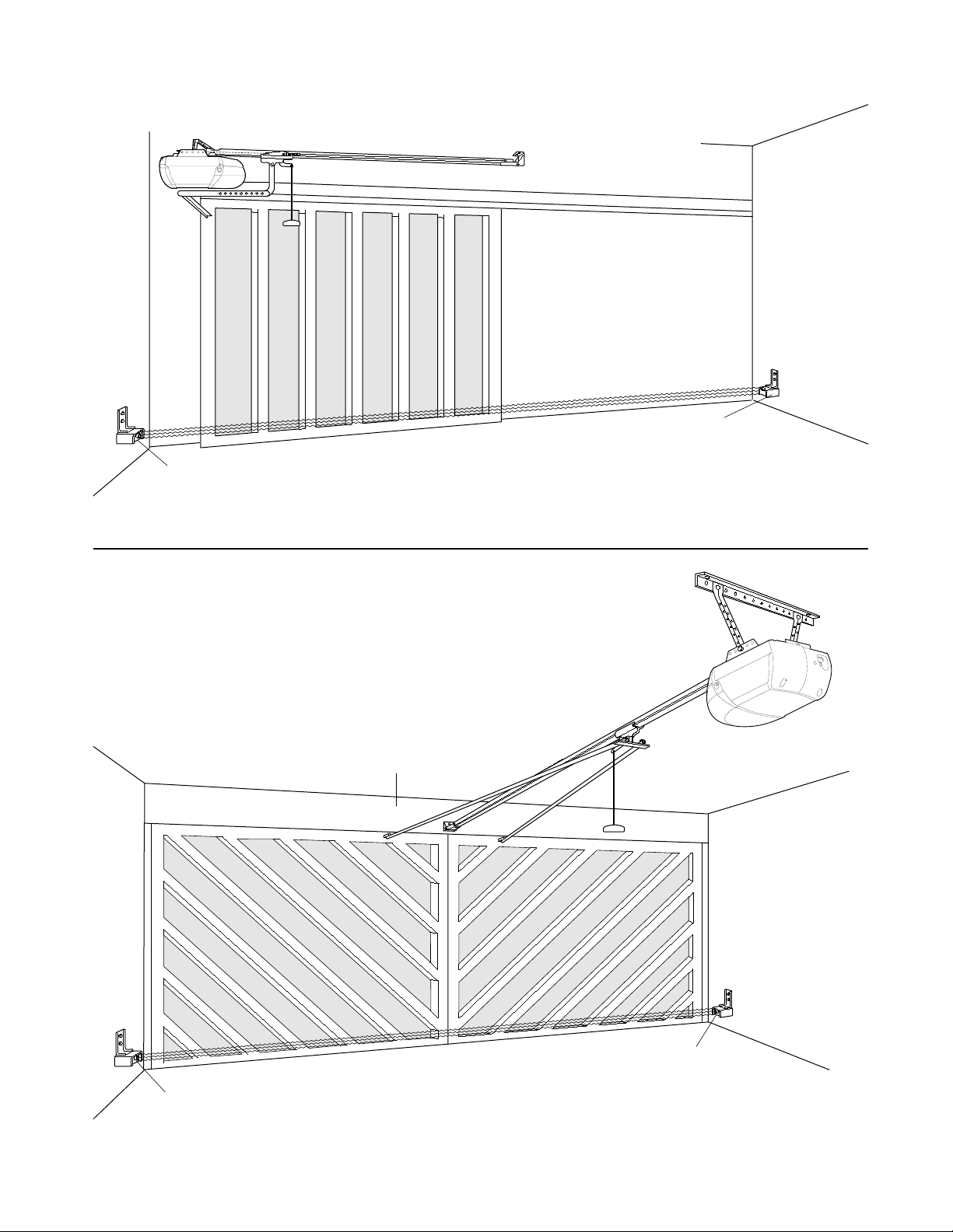
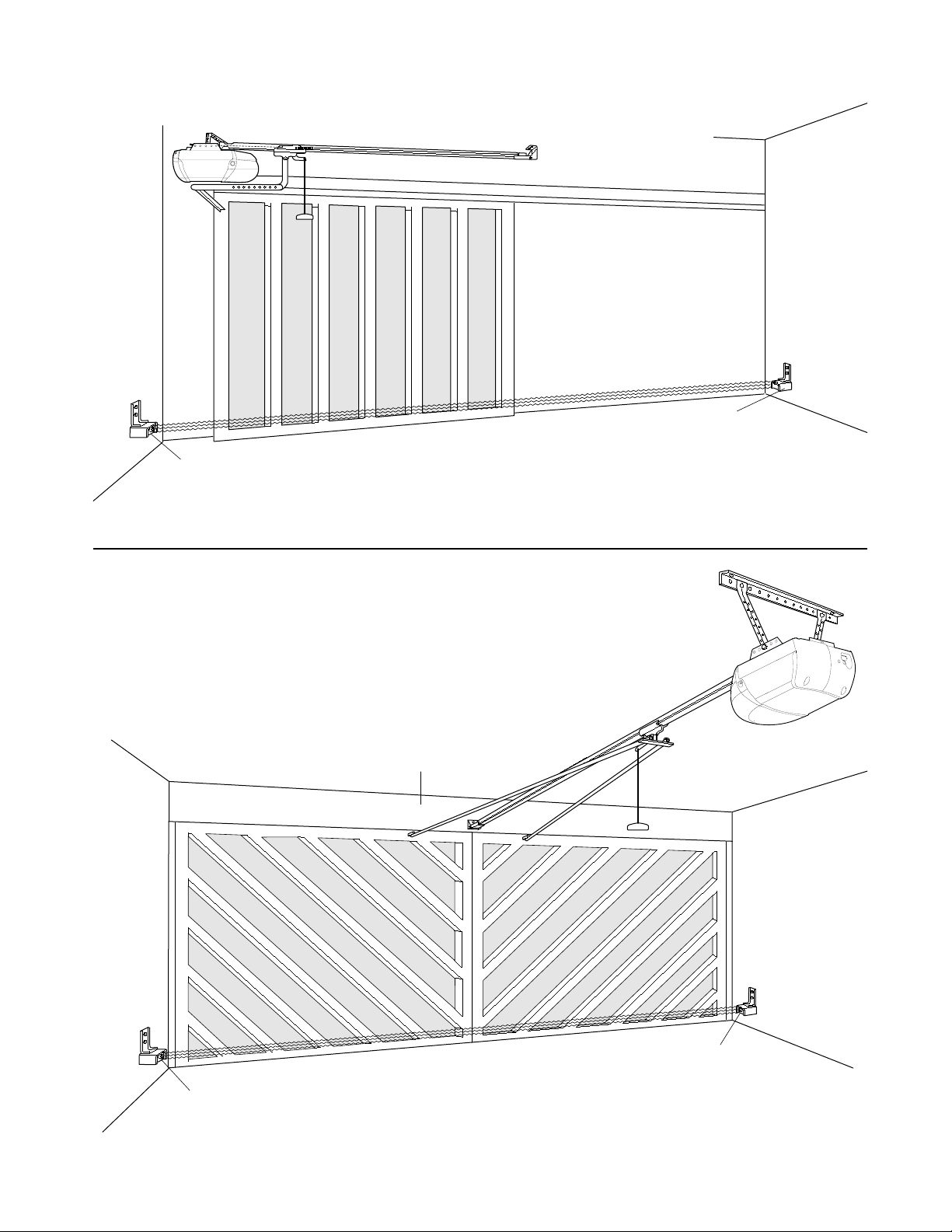
VIEW OF COMPLETED OPENER INSTALLATION ON A SLIDING DOOR
VIEW OF COMPLETED OPENER
INSTALLATION ON A SWINGING DOOR
Sensor Beam 6" max. above floor
Safety
Reversing
Sensor
Safety
Reversing Sensor
Header Wall
Safety
Reversing
Sensor
Sensor Beam 6" max. above floor
Safety
Reversing
Sensor
Page 3
3
In order to ensure the proper operation of your safety
reverse feature, replace the assembly instructions in
your Owner’s Manual with the following assembly steps.
WARNING
ASSEMBLY STEP 1
Assemble the Rail & Install
the Trolley
To avoid installation difficulties, do not run the
garage door opener until instructed to do so.
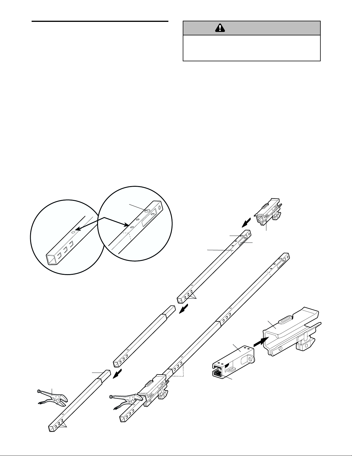
The front rail has a cut out “window” at the door end
(see illustration). The hole above this window is
larger on the top of the rail than on the bottom. A
smaller hole 3-1/2" (8.9 cm) away is close to the rail
edge. Rotate the back rail so it has a similar hole
close to the opposite edge, about 4-3/4" (12 cm)
from the far end. A 3-piece rail uses two back rails.
1. Align the rail sections on a flat surface exactly as
shown and slide the tapered ends into the larger
ones. Tabs along the side will lock into place.
2. Place the motor unit on packing material to protect
the cover, and rest the back end of the rail on top.
For convenience, put a support under the front
end of the rail.
3. As a temporary trolley stop, clamp a locking pliers
onto the rail, 8" (20 cm) from the end of the back
rail, as shown.
4. Check to be sure there are 4 plastic wear pads
inside the inner trolley. If they became loose
during shipping, check all packing material. Snap
them back into position as shown.
5. Connect the inner and outer trolleys as shown.
6. Slide the trolley assembly along the rail from the
front end to the locked pliers.
BACK RAIL
(TOP)
KEEP LARGER
HOLE ON TOP
FRONT RAIL
(TOP)
KEEP SMALL
HOLES ALONG
OPPOSITE
EDGE
OF RAILS
WARNING
Idler
Pulley
Hole
8" (20 cm) Distance from
Idler Pulley Hole
Trolley
Window
Cut-Out
Front Rail
(TO DOOR)
Locking Pliers
Tabs
Tapered
End
Tabs
Back Rails
(TO MOTOR
UNIT)
Outer Trolley
Inner Trolley
Wear Pads
Page 4

4
HARDWARE SHOWN ACTUAL SIZE
ASSEMBLY STEP 2
Fasten the Rail to the Motor Unit
• Insert a 1/4"-20 x 1-3/4 bolt into the cover
protection bolt hole on the back end of the rail as
shown. Tighten securely with a 1/4"-20 lock nut.
• Remove the two bolts from the top of the motor
unit.
• Attach spreaders to the U bracket by snapping
them into place.
• Place the U bracket, flat side down, on the motor
unit and align the bracket holes with the screw
holes. Fasten with the previously removed screws.
• Align the rail assembly with the top of the motor
unit. Slide the rail end onto the U-bracket, all the
way to the stops that protrude on the top and sides
of the bracket.
Motor Unit
Sprocket
"U" Bracket
Lock Nut
Bolts
SLIDE RAIL TO STOPS
ON TOP AND SIDES
OF BRACKET
Cover
Protection
Bolt Hole
Bolt
Hook Spreader
into Back Slots,
then Snap Tab
Into Front Slot
To avoid SERIOUS damage to opener, ONLY use bolts
mounted in the top of the motor unit.
WARNING
WARNING
WARNING
ASSEMBLY STEP 3
Install the Idler Pulley
• Lay the chain/cable beside the rail, as shown.
Grasp the end with the cable loop and pass
approximately 6' of cable through the window.
Allow it to hang until Assembly Step 5.
• Remove the tape from the idler pulley. The inside
center should be pre-greased. If dry, regrease to
ensure proper operation.
• Place the idler pulley into the window as shown.
• Insert the idler bolt from the top through the rail
and pulley. Tighten with a 3/8" lock washer and nut
underneath the rail until the lock washer is
compressed.
• Rotate the pulley to be sure it spins freely.
• Insert a 1/4"-20 x 1-3/4 bolt into the trolley stop
hole in the front of the rail as shown. Tighten
securely with a 1/4"-20 lock nut.
HARDWARE SHOWN ACTUAL SIZE
CAUTION
Bolt 1/4"-20 x 1-3/4
Lock Nut
1/4"-20
Chain and
Cable
Idler
Bolt
3/8" Lock
Washer
Trolley
Stop Hole
3/8" Nut
Pulley
Washer
Grease
Inside Pulley
Idler
Pulley
Cable Loop
Bolt
Rail
Nut
Trolley
Stop Hole
Idler Pulley
Bolt
Idler Bolt
Bolt 1/4"-20 x 1-3/4
Lock Nut 1/4"-20
Nut 3/8"
Lock Washer 3/8"
Page 5

5
ASSEMBLY STEP 4
Install the Chain/Cable
and Attach the Sprocket Cover
1. Pull the cable around the idler pulley and toward
the trolley.
2. Connect the cable loop to the retaining slot on the
trolley, as shown:
• From below, push pins of master link bar up
through cable loop and trolley slot.
• Push master link cap over pins and past pin
notches.
• Slide clip-on spring over cap and onto pin
notches until both pins are securely locked in
place.
3. With the trolley against the pliers, dispense the
remainder of the cable/chain along the rail toward
the motor unit and around the sprocket. The
sprocket teeth must engage the chain.
4. Check to make sure the chain is not twisted, then
connect it to the threaded shaft with the
remaining master link.
5. Thread the inner nut and lock washer onto the the
trolley shaft.
6. Insert the trolley threaded shaft through the hole
in the trolley. Be sure the chain is not twisted.
7. Loosely thread the outer nut onto the trolley shaft.
8. Remove the locking pliers.
9. Align the tabs on the sprocket cover with the
slots in the mounting plate. Squeeze
cover and insert tabs in slots.
To avoid possible SERIOUS INJURY to fingers from
moving garage door opener:
• ALWAYS keep hand clear of sprocket while
operating opener.
• Securely attach sprocket cover BEFORE operating.
WARNING
Idler
Pulley
Round
Hole
Master
Link Clip-On
Spring
Master
Link Cap
Trolley
Threaded
Shaft
Master
Link Bar
Master
Link Bar
Pin
Notch
Cable
Install Chain
and Cable
in this Direction
Opener
Back Tab
Slot
Mounting
Plate
Sprocket
Cover
WARNING
Dispensing Carton
Leave Chain and Cable
Inside Dispensing
Carton to Prevent Kinking.
Keep Chain and Cable
Taut When Dispensing
Page 6

ASSEMBLY STEP 5
Tighten the Chain
• Spin the inner nut and lock washer down the
threaded shaft, away from the trolley.
• To tighten the chain, turn outer nut in the direction
shown (Figure 1).
• When the chain is approximately 1/2" (1 cm) above
the base of the rail at its midpoint, re-tighten the
inner nut to secure the adjustment.
Sprocket noise can result if chain is too loose.
When installation is complete, you may notice some
chain droop with the door closed. This is normal. If
the chain returns to the position shown in Figure 2
when the door is open, do not re-adjust the chain.
NOTE: During future maintenance, ALWAYS pull the
emergency release handle to disconnect trolley
before adjusting chain.
NOTE: You may notice loosening of chain after
Adjustment (Test the Safety Reversal System).
Check for proper tension and readjust chain if
necessary. Then repeat Adjustment.
Figure 1
Figure 2
INSTALLATION
6
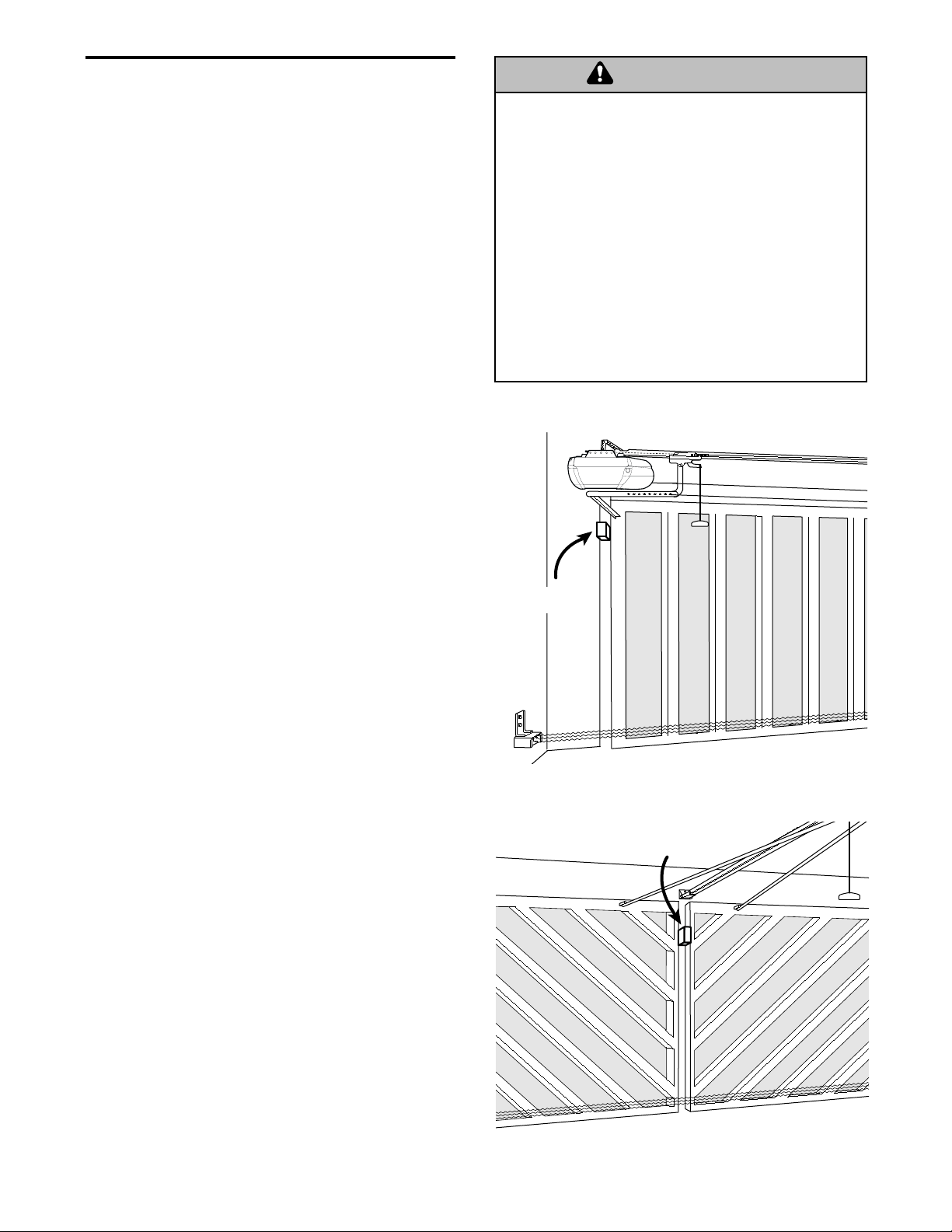
NOTE: It is recommended that you attach fine mesh or screening across the inside of swinging or sliding doors
in order to prevent intruders from reaching through the bars and releasing the trolley from the door arm or
pressing the door control button.
You have now finished assembling your garage
door opener. Please read the following warnings
before proceeding to the installation section.
IMPORTANT INSTALLATION INSTRUCTIONS
To reduce the risk of severe injury or death to persons:
WARNING
1. READ AND FOLLOW ALL INSTALLATION
INSTRUCTIONS
2. Install ONLY on a door which is in good repair and
moves freely.
3. Disable all locks and remove all ropes connected to
the door before installing the opener. Ropes connected
to a door can cause entanglement and DEATH.
4. If possible, install the opener 7 feet or more above
floor with manual release handle mounted 6 feet
above the floor. Removing the manual release rope
and handle and/or disabling the trolley release lever
can cause SERIOUS PERSONAL INJURY or DEATH.
5. Do not connect the opener to power source until
instructed to do so.
6. Locate the door control push button within sight of
the door at a minimum height of 5 feet where small
children cannot reach and away from all moving
parts of the door. Operating a door control push
button that is located out of sight of the door can
lead to SERIOUS PERSONAL INJURY or DEATH
from entrapment.
7. Install the User Safety Instruction Label on the wall
adjacent to the control button and the Maintenance
Instruction Label in a prominent location on the
inside or alongside of the door.
8. Upon completion of the installation, the door must
reverse when it comes in contact with a 2x4 board
inserted between the wall and the door or between
the swinging door sections (see page 8).
9. Do not wear watches, rings or loose clothing while
installing or servicing an opener. Jewelry or loose
clothing can be caught in the mechanism of the door
or the opener.
10. For opener security, install a guard to protect the rear
panel from being activated from outside the door.
To Tighten Outer Nut
Outer
Nut
Lock
Washer
To Tighten
Inner Nut
Trolley
Shaft
Inner Nut
Chain
(1 cm)
1/2 Inch
Base of Rail
Mid length of Rail
WARNING
Page 7

7
IMPORTANT SAFETY INSTRUCTIONS
To reduce the risk of severe injury or death to persons:
WARNING
1. READ AND FOLLOW ALL WARNINGS AND
INSTRUCTIONS.
2. ALWAYS keep remote controls out of reach of children.
NEVER permit children to operate or play with garage
door control push buttons or remote controls.
3. ONLY activate garage door when it can be seen clearly,
it is properly adjusted, and there are no obstructions to
door travel.
4. ALWAYS keep garage door in sight until completely
closed. NO ONE SHOULD CROSS THE PATH OF THE
MOVING DOOR.
5. Safety Reversal system MUST be tested every month.
The door MUST reverse on contact with a 2x4 board
inserted between the wall and the sliding door or
between the swinging door sections (see page 8).
6. If one control (force or travel limits) is adjusted, the
other control may also need adjustment.
7. After any adjustments are made, the safety reversal
system MUST be tested.
8. Disabling the trolley manual release lever or removing
the emergency release rope and handle will prevent
the door from being opened in an emergency, and can
cause SERIOUS INJURY OR DEATH.
9. Keep door in good repair and make sure it moves
freely. An improperly operating swinging or sliding
door could result in SEVERE PERSONAL INJURY OR
DEATH. Any necessary repairs should be made by a
qualified person.
10. Disconnect the electric power to the opener before
making any repairs or removing the covers.
11. The opener chassis MUST be protected from rain
and/or moisture.
12.
SAVE THESE INSTRUCTIONS
.
OPERATION
WARNING
Page 8
114A1633B ©2002 Printed in Mexico
SLIDING DOOR INSTALLATION
SWINGING DOOR INSTALLATION
ADJUSTMENT
Follow the Adjustment Steps below
for proper testing of the Safety
Reverse System.
1. The opener must reverse if the door comes in
contact with an obstruction. A closing door should
reverse with little effort, and open completely.
Refer to Adjustment Step 2 in Owners Manual
for instructions.
2. At completion of installation of opener and testing
of reversing feature in #1 above, the 1 inch
reversal test must be completed. (Use 2x4 board
laid flat against the wall or door edge.)
• On a sliding door door, place a 2x4 board
between the door and wall of a closing door.
Door must reverse on the board and open
completely. Repeat at opposite wall if two
openers are installed.
• On a swing out door, insert a 2x4 board between
the closing door sections. Door sections must
reverse and swing open completely.
• If the door stops on the obstruction, it is not
traveling far enough in the closing direction.
Increase the DOWN limit adjustment screw
counterclockwise 1/4 turn. Repeat test.
• When the door reverses on a 2x4 board, remove
the obstruction and run the opener through
complete travel cycle to test adjustment.
• If the door will not reverse after repeated
adjustment attempts, call for trained door
systems technician.
IMPORTANT SAFETY CHECK
Repeat Adjustment Steps in Owners Manual
after:
• Each adjustment of door arm length, force controls
or limit controls.
• Any repair to or adjustment of the garage door
(including springs and hardware).
• Any repair to or buckling of the garage floor.
• Any repair to or adjustment of the opener.
Without a properly installed safety reversal system,
persons (particularly small children) could be
SERIOUSLY INJURED or KILLED by a closing garage door.
• Too much force on garage door will interfere with
proper operation of safety reversal system.
• NEVER increase force beyond minimum amount
required to close garage door.
• NEVER use force adjustments to compensate for a
binding or sticking garage door.
• If one control (force or travel limits) is adjusted, the
other control may also need adjustment.
• After ANY adjustments are made, the safety reversal
system MUST be tested. Door MUST reverse on
contact with one-inch high object (or 2x4 laid flat)
on floor.
WARNING
WARNING
2x4
Door/Wall
Obstruction
2x4 Obstruction
Page 9

ANEXO AL MANUAL
DEL PROPIETARIO ABRIDOR
PARA PUERTA DE COCHERA
Instrucciones Complementarias
Instalación y Prueba del Abridor en un Portón
con Bisagras o Corredizo
Si el abridor de portón no se instala, se opera, se prueba y
recibe el mantenimiento estrictamente de acuerdo a estas
instrucciones, el resultado puede ser lesiones personales serias
e inclusive la muerte si una persona queda atrapada.
• Siga cuidadosamente todas las instrucciones de instalación y
de seguridad.
• Conservar este instructivo.
ADVERTENCIA
ADVERTENCIA
Page 10
2
VISTA DE UNA INSTALACIÓN TERMINADA DE UN ABRIDOR EN UN PORTÓN CORREDIZO
VISTA DE LA INSTALACIÓN TERMINADA
DE UN ABRIDOR EN UN PORTÓN CON BISAGRA
Rayo del sensor a una distancia
Sensor de
Reversa de
Seguridad
máxima de 15 cm (6 pulg.)
Sensor de
Reversa de
Seguridad
Pared Frontal
Sensor de
Reversa de
Seguridad
Rayo del sensor a una distancia
máxima de 15 cm (6 pulg.)
Sensor de
Reversa de
Seguridad
Page 11

El riel delantero tiene una "ventana" cortada en el extremo
de la puerta (vea la ilustración). El orificio que se
encuentra arriba de esta ventana es más grande en la
parte superior del riel que en la parte inferior. Hay un
orificio más pequeño que se encuentra a 8.75 cm (3-1/2
pulg.) y está cerca de la orilla del riel. Gire el riel posterior
de manera que tenga un orificio similar cerca de la orilla
opuesta, más o menos a 11.87 cm (4-3/4 pulg.) del
extremo. Un riel de tres partes utiliza dos rieles posteriores
1. Alínee las secciones del riel sobre una superficie plana
exactamente como se indica y luego deslice los
extremos más pequeños dentro de los más grandes.
Las pestañas que se encuentran a lo largo de los lados
del riel se van a ajustar en su lugar.
2. Coloque el motor sobre el material de empaque para
proteger la cubierta del mismo y apoye el extremo
posterior del riel encima. Para que le resulte más
cómodo, ponga algún tipo de apoyo bajo el extremo
delantero del riel.
3. Como un tope temporario del trole, coloque tenazas de
calce a manera de mordaza sobre el riel a 20 cm
(8 pulg.) del extremo del riel posterior, según ilustrado.
4. Inspeccione para asegurarse que hayan 4 zapatas
plásticas de desgaste detro del trole interno. Si los
cojinetes se han soltado durante el transporte, revise
todo el material de empaque. Ponga los cojinetes de
desgaste en su lugar como se indica.
5. Conecte los troles interno y externo como aparece en la
ilustración.
6. Deslice el conjunto del trole a lo largo del riel desde el
extremo delantero a las tenazas calzadas.
3
Para asegurar la operación adecuada del dispositivo de
seguridad de reversa, sustituir las instrucciones de ensamble
del Manual del propietario con los siguientes pasos para el
ensamble.
ADVERTENCIA
MONTAJE, PASO 1
Monte el riel e instale el trole
Para evitar problemas en la instalación, no opere el
abridor hasta que se le ordene hacerlo.
Riel delantero
(A LA PUERTA)
Ventana
Pinzas con seguro
Orificio de
la polea loca
Distancía de 20 cm (8 pulg.)
desde el orificio
de la polea loca
Pestañas
Pestañas
Rieles
posteriores
(AL MOTOR)
Trole
Extremo más
pequeño
Trole interno
Cojinetes de desgaste
Trole externo
Extremo más
pequeño
MANTENGA
EL ORIFICIO
MÁS GRANDE
HACIA ARRIBA
RIEL DELANTERO
(PARTE
SUPERIOR)
MANTENGA LOS
ORIFICIOS PEQUEÑOS
A LO LARGO DE LA
ORILLA OPUESTA
DE LOS RIELES
RIEL POSTERIOR
(PARTE
SUPERIOR)
ADVERTENCIA
Page 12

4
Para evitar un daño SEVERO al abridor, use SOLO pernos
montados en la parte superior de la unidad del motor.
ADVERTENCIA
ADVERTENCIAADVERTENCIA
ESTAS PIEZAS SE MUESTRAN EN
SU TAMAÑO NORMAL
MONTAJE, PASO 2
Sujete el riel al motor
• Coloque un perno de 1/4-20x1-3/4 de pulg. dentro del
orificio de la cubierta de protección que se encuentra en
el extremo posterior del riel, como se indica en la
ilustración. Apriete bien el perno con tuerca de
1/4-20 de pulg.
• Extraiga los dos pernos del tope de la unidad del motor.
• Coloque los desplegadores en la ménsula en 'U'.
Escuchará un chasquido cuando quedan en su lugar.
• Ponga la ménsula en 'U' sobre el motor con el lado
plano hacia abajo y alínee los orificios de la ménsula
con los orificios de los tornillos. Sujete con los tornillos
que quitó antes.
• Alínee el riel con la parte superior del motor. Deslice el
extremo del riel en la ménsula en 'U', hasta los topes
que sobresalen en la parte superior y a los lados de la
ménsula.
MONTAJE, PASO 3
Instale la polea loca
• Acomode la cadena o cable a un lado del riel, como se
ilustra. Tome el extremo del cable que tiene una lazada
y pase aproximadamente 6' de cable a través de la
ventana. Deje el cable colgando hasta llegar al Paso 5
de Montaje.
• Retire la cinta de la polea loca. El interior del centro
debe estar engrasado. Si se ha secado, vuelva a
engrasarlo para asegurar que la operación sea
adecuada.
• Coloque la polea loca dentro de la ventana como
aparece en la ilustración.
• Inserte el perno loco desde la parte superior y a través
del riel y la polea. Apriete con una roldana y una tuerca
de 3/8 de pulg. por debajo del riel hasta que la roldana
quede comprimida.
• Haga girar la polea para cerciorarse de que da vuelta
libremente.
• Pase un perno de 1/4-20x1-3/4 de pulg. por el orificio de
paro del trole que se encuentra en la parte delantera del
riel, como aparece en la ilustración. Apriete bien con
una tuerca de 1/4-20 de pulg.
ESTAS PIEZAS SE MUESTRAN EN SU TAMAÑO NORMAL
PRECAUCIÓN
Pernos
Ménsula en 'U'
Perno
Orificio para
el perno en
la cubierta
de protección
DESLICE EL RIEL HASTA
LOS TOPES QUE ESTÁN EN
Tuerca
LA PARTE SUPERIOR Y A LOS
LADOS DE LA MÉNSULA
Polea del motor
Enganche
el desplegador
en las ranuras
posteriores,
luego coloque
las pestañas
dentro de la
ranuras delanteras.
Perno de 1/4-20x1-3/4 de pulg.
Tuerca de
1/4-20 de pulg.
Cadena y
cable
Perno
loco
Roldana de
3/8 de pulg.
Orificio de
paro del trole
Tuerca de
3/8 de pulg.
Per no
Polea
Roldana
Engrase el interior
de la polea
Polea loca
Lazada del cable
Riel
Tuerca
Per no
Orificio de
paro del trole
Polea loca
Perno loco
Perno de 1/4-20x1-3/4 de pulg.
Tuerca de
1/4-20 de pulg.
Tuerca de
3/8 de pulg.
Roldana de
3/8 de pulg.
Page 13

MONTAJE, PASO 4
Instale la cadena o cable y coloque
la cubierta de la polea
1. Jale el cable alrededor de la polea loca y hacia el trole.
2. Conecte la lazada del cable a la ranura de retención del
trole, como aparece en la ilustración:
• Empuje los pernos de la barra de enlace maestro
desde abajo hacia arriba y páselos a través de la
lazada del cable y la ranura del trole.
• Empuje la tapa del enlace maestro sobre los pernos y
las ranuras de los pernos.
• Deslice el resorte de clip sobre la tapa y sobre las
ranuras de los pernos hasta que los dos pernos estén
bien colocados y seguros en su lugar.
3. Con el trole contra las pinzas, alimente el resto del
cable o cadena a lo largo del riel, hacia el motor y
alrededor de la polea. Los dientes de la polea deben
engancharse en la cadena.
4. Revise para cerciorarse de que la cadena no esté
torcida, luego conéctela a la flecha roscada con el
enlace maestro restante.
5. Enrosque la tuerca interna y la roldana en la flecha del
trole.
6. Pase la flecha roscada del trole a través del orificio que
tiene el trole. Cerciórese de que la cadena no esté
torcida.
7. Ponga la tuerca externa en la flecha del trole, dejándola
floja.
8. Quite las pinzas con seguro.
9. Alínee las pestañas de la cubierta de la polea con las
ranuras de la placa de montaje. Oprima la cubierta e
inserte las pestañas en las ranuras.
Para evitar posibles LESIONES GRAVES en los dedos causadas
por las partes móviles del abridor de puerta de cochera:
• SIEMPRE tenga las manos lejos de la polea mientras esté
funcionando el abridor.
• Ponga la cubierta de la polea ANTES de hacer funcionar
el abridor.
5
ADVERTENCIA
Abridor
Polea
loca
Orificio
redondo
Flecha
roscada
del trole
Cable
Indentación
del perno
Tapa del
enlace maestro
Resorte
de clip del
enlace
maestro
Barra del
enlace maestro
Cubierta
de la polea
Placa de
montaje
Ranura de la
pestaña posterior
Instale la Cadena
y Cable en
esta Dirección
ADVERTENCIA
Cartón para alimentar
el cable/cadena
Deje la cadena y
el cable dentro del cartón
para evitar que se tuerza.
Mientras alimente la cadena y
el cable debe mantenerlos tensos
Page 14

Figura 1
Figura 2
6
Ya terminó de armar su abridor de puerta de cochera,
por favor lea les siguientes advertencias antes de
continuar a la Sección de instalación.
IMPORTANTES INSTRUCCIONES DE INSTALACION
:
Para reducir el riesgo de lesiones personales severas
e inclusive la muerte:
ADVERTENCIAADVERTENCIA
1. LEER Y SEGUIR TODAS LAS INSTRUCCIONES DE INSTALACION
2. Instalar solamente en un portón que se encuentre en buenas
condiciones de operación y se mueva libremente.
3. Inhabilitar todos los seguros y quitar todas las cuerdas
conectadas al portón antes de instalar el abridor. Las cuerdas
conectadas al portón pueden enredarse y ocasionar inclusive
la muerte.
4. De ser posible, instalar el abridor a una altura de 7 pies o más
del piso, con la manija del desenganchador manual montado
a 6 pies del piso. Remover la cuerda y la manija del
desenganchador manual y/o inhabilitar la palanca que
desengancha el carrito puede ocasionar lesiones personales
serias e inclusive la muerte.
5. No conectar el abridor al suministro de energía hasta que se
indique hacerlo.
6. Colocar el botón de control del portón a la vista desde el
portón y a una altura mínima de 5 pies, donde los niños
pequeños no puedan alcanzarlo y lejos de las piezas móviles
del portón. Colocar el botón de control del portón en un lugar
donde no se vea desde el portón puede conducir a serias
lesiones personales e inclusive la muerte si una persona
queda atrapada.
7. Colocar la etiqueta de Instrucciones de seguridad del usuario
sobre la pared, junto al botón de control y colocare la etiqueta
de Instrucciones de mantenimiento en un lugar prominente en
el interior o a lado del portón.
8. Una vez terminada la instalación, el portón debe dar marcha
atrás al entrar en contacto con una tabla de 2 x 4 que se
coloque entre la pared y la puerta corrediza del portón, o bien
entre las secciones del portón con bisagras (ver la página 8).
9. No usar relojes de pulso, anillos ni prendas de ropa sueltas al
instalar o dar servicio a un abridor. Las piezas de joyería o las
prendas de ropa sueltas pueden atorarse en el mecanismo del
portón o del abridor.
10. Por razones de seguridad, instalar una guarda para proteger
el panel trasero y evitar que se active desde fuera del portón.
NOTA: Se recomienda colocar una malla fina a través del portón corredizo o con bisagras, con el objeto de evitar que
cualquier intruso alcance el botón de control o el brazo que desengancha el carrito.
MONTAJE, PASO 5
Apriete la cadena
• Gire la tuerca interna y ajuste la roldana; baje ambas por
la flecha roscada, alejándolas del trole.
• Para apretar la cadena, gire la tuerca externa en la
dirección que se indica en la Figura 1.
• Una vez que la cadena esté aproximadamente 1.25 cm
(1/2 pulg.) arriba de la base del riel en su punto medio,
vuelva a apretar la tuerca interna para asegurar el ajuste.
Si la cadena queda demasiado floja la polea puede hacer
ruido.
Una vez terminada la instalación, es posible que observe
que la cadena cuelga un poco cuando la puerta está
cerrada, pero esto es normal. Si la cadena regresa a la
posición que se ilustra en la Figura 2 cuando la puerta
está abierta, no vuelva a ajustar la cadena.
NOTA: En el futuro, cuando le dé mantenimiento
SIEMPRE jale la manija de emergencia para desconectar
el trole antes de ajustar la cadena.
NOTA: Usted puede notar que la cadena se ha aflojado
después del ajuste (Prueba el sistema reversible de
seguridad). Verifique que la tensión sea correcta y reajuste
la cadena de ser necesario. A continuación repita el ajuste.
INSTALACIÓN
Para apretar
la tuerca externa
Cadena
Base del riel
Tuerca
externa
Mitad del riel
Roldana
Para apretar
la tuerca interna
1/2 pulg.
Flecha
del trole
Tuerca interna
ADVERTENCIA
Page 15

7
INSTRUCCIONES IMPORTANTES DE SEGURIDAD
Para reducir el riesgo de lesiones personales
severas inclusive la muerte:
ADVERTENCIAADVERTENCIA
1. LEA Y RESPETE TODAS LAS ADVERTENCIAS Y LAS
INSTRUCCIONES DE OPERACIÓN
2. SIEMPRE conserve los controles remotos lejos del alcance de
los niños. NUNCA permita que los niños operen o jueguen con
los botones del control de la puerta de la cochera ni con los
controles remotos.
3. SÓLO active la puerta de la cochera siempre y cuando la
puedan ver con claridad, esté debidamente ajustada y no haya
ninguna obstrucción en el recorrido de la puerta al cerrarse.
4. SIEMPRE tenga la puerta de la cochera a la vista hasta que esté
completamente cerrada. NADIE DEBE ATRAVESAR EL
RECORRIDO DE LA PUERTA CUANDO ESTÁ EN MOVIMIENTO.
5. El sistema reversible de seguridad DEBE probarse cada mes.
La puerta DEBE revertirse al tocar la tabla de 2x2 insertada
entre la pared y la puerta corrediza o entre las secciones de la
puerta giratoria (vea la página 8).
6. Si se ajusta uno de los controles (límites de la fuerza o del
recorrido), es posible que sea necesario ajustar también el
otro control.
7. Después de llevar a cabo cualquier ajuste, SE DEBE probar el
sistema de reversa de seguridad.
8. El inhabilitar la palanca de desenganche manual del trole o el
extraer la soga y manija de desenganche de emergencia
impide que la puerta se abra en una emergencia, y puede
causar LESIONES GRAVES O LA MUERTE.
9. Mantega la puerta en buen estado y asegúrese que se mueve
libremente. Una puerta giratoria o corrediza mal ajustada
puede resultar en LESIONES PERSONALES GRAVES O LA
MUERTE. Toda reparación necesaria debe ser efectuada por
una persona calificada.
10. Desconectar el suministro de energía del abridor antes de
hacer cualquier reparación o de quitar las cubiertas.
11. El chasis del abridor debe estar protegido contra la lluvia y/o
la humedad.
12.
CONSERVAR ESTAS
INSTRUCCIONES.
OPERACIÓN
ADVERTENCIA
Page 16

Si el sistema de reversa de seguridad no se ha instalado
debidamente, las personas (y los niños pequeños en
particular) podrían sufrir LESIONES GRAVES o incluso LA
MUERTE cuando se cierra la puerta de la cochera.
• Si el límite de la fuerza de la puerta de la cochera es excesivo
habrá de interferir con la operación adecuada del sistema de
reversa de seguridad.
• NUNCA aumente la fuerza más allá de la cantidad mínima que
se requiera para cerrar la puerta de la cochera.
• NUNCA use los ajustes de la fuerza para compensar si la
puerta de la cochera se pandea o se atora.
• Si se ajusta uno de los controles (límites de la fuerza o del
recorrido), es posible que sea necesario ajustar también el
otro control.
• Después de llevar a cabo cualquier ajuste, SE DEBE probar el
sistema de reversa de seguridad. La puerta DEBE retroceder
al entrar en contacto con un objeto de 2.5 cm (1 pulg) de
altura (o bien un pedazo de madera de 5 x 10 cm (2x4)
acostado en el piso.
114A1633B ©2002 Impreso en México
INSTALACIÓN DE UN PORTÓN CORREDIZO
INSTALACIÓN DE UN PORTÓN
CON BISAGRA
AJUSTE
Siga los Pasos de Ajuste de abajo para
una prueba apropiada del Sistema
Reversible de Seguridad.
1. El abridor debe dar marcha atrás al entrar en contacto
con una obstrucción. Un portón que está cerrándose
debe dar marcha atrás con muy poco esfuerzo y abrir
completamente. Consultar las instrucciones que
aparecen en el Paso 2 del ajuste del Manual del
Propietario.
2. Una vez terminada la instalación del abridor y hecha la
prueba del dispositivo de reversa como se indica en el
punto 1 anterior, deberá realizarse la prueba de reversa
de una pulgada. (Usar una tabla de 2 x 4 colocada
sobre la pared o en la orilla del portón).
• En un portón corredizo, colocar una tabla de 2 x 4
entre la puerta y la pared cuando el portón se esté
cerrando. El portón debe dar marcha atrás sobre la
tabla y abrirse completamente. Repetir en la pared
opuesta si se han instalado dos abridores.
• En un portón con bisagras que abran hacia fuera,
insertar una tabla de 2 x 4 entre las secciones del
portón que se están cerrando. Las secciones del
portón deben dar marcha atrás y abrirse
completamente.
• Si el portón se detiene ante la obstrucción, el recorrido
no es suficiente en la dirección de cerrado. Aumentar
el límite HACIA ABAJO, girando el tornillo de ajuste 1/4
de vuelta en dirección opuesta a las manecillas del
reloj. Repetir la prueba.
• Cuando el portón dé marcha atrás al toparse con la
tabla de 2 x 4, retirar la obstrucción y hacer funcionar
el abridor un ciclo completo de su recorrido para
probar el ajuste.
• Llame a un técnico capacitado de sistemas de puerta,
si la puerta no se revierte después de repetidos
intentos de ajuste.
IMPORTANTE VERIFICACIÓN DE SEGURIDAD
Repita los pasos de ajuste del Manual del
Propietario después de:
• Hacer ajustes al largo del brazo de la puerta, a los
controles de fuerza o a los controles de límite
• Reparar o ajustar la puerta de cochera (incluyendo
resortes o piezas de ferretería).
• Reparar el piso de la cochera
• Reparar o ajustar el abridor.
ADVERTENCIA
ADVERTENCIA
Obstrucción
de 2x4 en la
pared y puerta
Obstrucción de 2x4
 Loading...