

Page 1
Safety Photoelectric
Beam System 771ANZ
The 771ANZ Photoelectric Beam System is designed to
i
ncrease the safety and functionality of your garage door
or gate motor.
The system uses an invisible beam across the garage
d
oor or gate opening. If an obstruction breaks the light
beam while the door/gate is closing, the door/gate will stop
and reverse to full open position.
T
he units may be installed on either side of the door so
long as the sun never shines directly into the receiving eye
lens. NOTE: The brackets must be connected and fastened so that the sending and receiving eyes face each
other.
The Beams
must
be securely fastened to a solid surface
such as a stud wall for garage doors or bollard or wall for
gates.
The invisible light beam path must be unobstructed.
Ensure no part of the door (or door tracks, springs, hinges,
rollers or other hardware) interrupts the beam while the
door or gate is closing.
Red LED
M
UST BE ON
Safety Reversing Sensor
6
" (15 cm) max. above floor
S
afety Reversing Sensor
4" / (100mm) max. above floor
100-150mm
Suitable for Gate Motors and
Garage Door Application
ASSEMBLY PROCEDURES
To protect small children, install the Protector System™
no higher than (100mm) above the floor for garage door.
For gates consult your owners manual for requirements.
Disconnect power to the garage door opener before
installing the 771ANZ
WARNING!
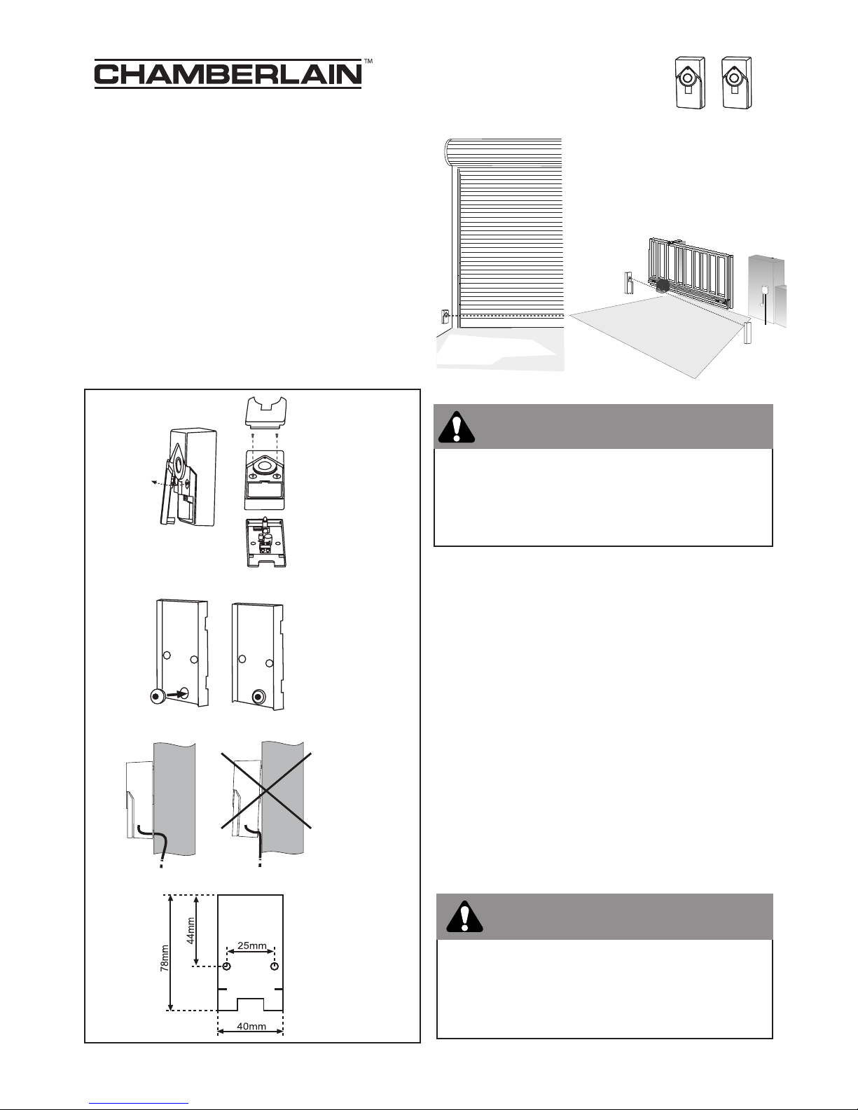
• Run two wires (not provided) from the sending eye and
the recieving eye back to your garage door motor or
gate control board.
• Ensure the cable exit point in you wall or bollard is
exactly the same on both sides.
• Remove the cover plate from the base of the beam as
illustrated in fig 1.
• Insert the grommet (provided) as illustrated in fig 2.
• Mark out the fastening positions as illustrated in fig 3,
take not of the cable exit to ensure the cable enters
through the grommets.
• Terminate cables to positive and negative terminals
and take note of the polarity before connecting to the
garage door motor or gate motor as outlined of pages
2 and 3.
fig 1
fig 2
fig 3
Review all safety warnings outlined in your door
operator owner’s manual. Ensure that the door/gate
and all there fixtures and fittings are in good condition.
WARNING!
1
Page 2
6
0s
1
20s
180s
O
–
grey
white
2
white
M
T60/P
MT600 / MT1000
M
T5580
1. grey
2. white
white wires
t
wisted together
white/black
wires twisted
together
3
grey
white wires
white/black
wires
white/black
wires twisted
t
ogether
white wires
twisted together
MR800a /MR600a
grey
white
white wires
twisted together
white/black
wires twisted
together
2
1
3
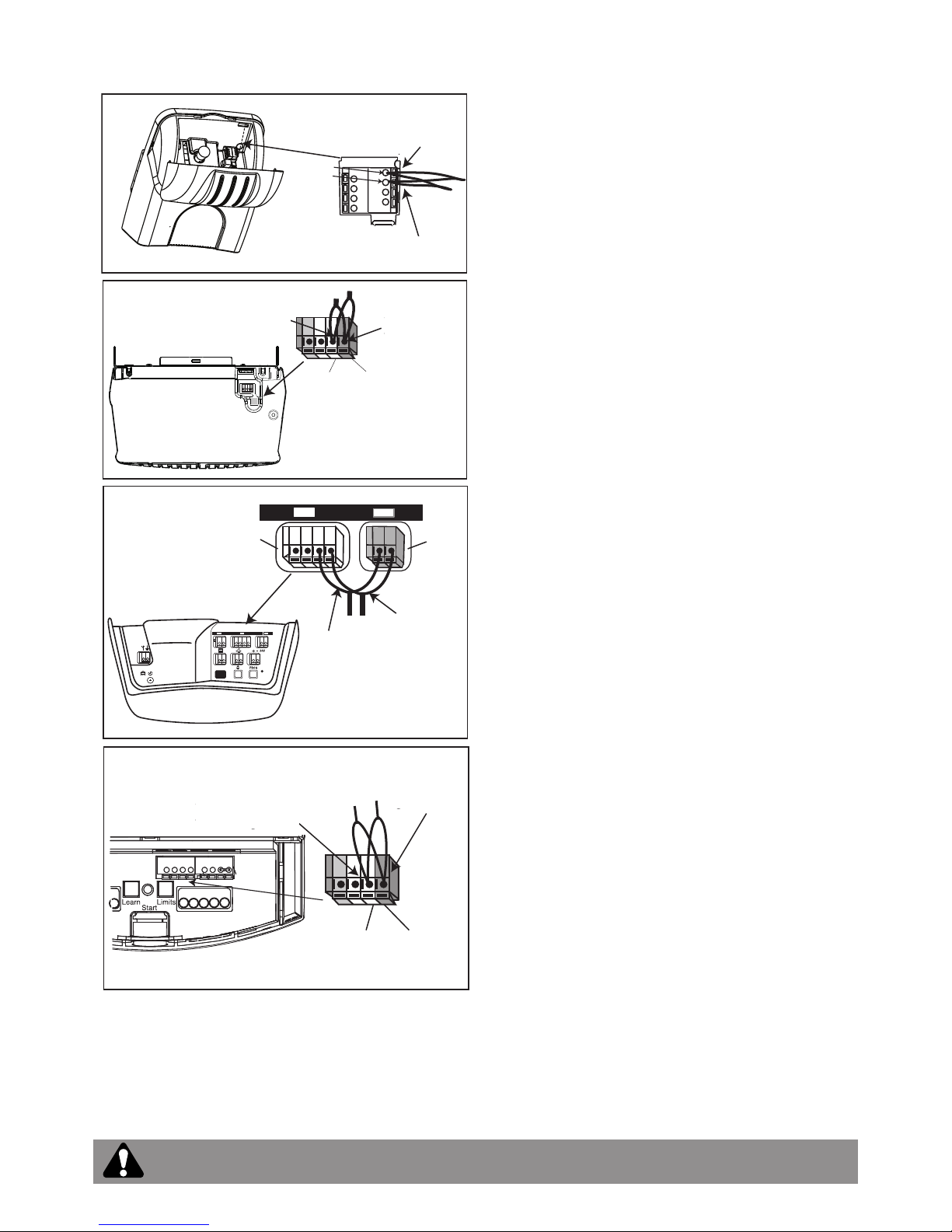
Wiring Connections Merlin Professional
MT60/P connections
Open the lens cover on the front of the unit to access the
connection terminals. Strip all wires back about 10mm
t
wist the two (-) wires together, then twist the the two (+)
wires together. Trim the twisted wires to approximately
6
mm. Use a small screwdriver or pen to hold down the
spring terminals, insert the (+) wires into the grey terminal
(1), then terminate the (-) (only) wires into the white termi-
nal (2).
MT5580 (all models) connection
Locate the connection terminals on the back of the unit.
Strip all wires back about 10mm, twist the two (-) wires
together, then twist the two (+) wires together. Trim the
twisted wires to approximately 6mm. Use a small screwdriver or pen to hold down the spring terminals, insert the
(+) wires into the grey terminal, then terminate the (-)
wires into the white terminal.
MT600 / MT1000 connections
Locate the terminals on the back of the unit. Strip all wires
back about 10mm, twist the two (-) wires together, then
twist the two (+) wires together. the twisted wires to
approximately 6mm. Use a small screwdriver or pen to
hold down the spring terminals, insert the (+) wires into the
grey terminal (3), then terminate the (-) wires into the white
terminal (2).
NOTE: Optional connections: Connect the (-) wires and
(+) wires into separate terminal on the back of the unit as
illustrated above. This may be required if larger diameter
cable extensions have been used to extend wiring.
Setting Autoclose MR600A, MR800A/ MT1000 (ONLY)
Auto Close NOTE:
Ensure that the trim pot is set to 0s when terminating cables. Beams must be uninterrupted for up to five minutes
after turning on to initialise. (The Trim pot should not be adjusted during this 5 minute initialising period)
.
Note: After the beams are initialised they are fail safe i.e. if they removed, the motor will not close until the
beams are re(-)installed.
MR600a / MR800a connections
Gently lift the diffuser on the base of the motor to access
the terminals. Strip all wires back about 10mm, twist the
two (-) wires together, then twist the two (+) wires together. Trim the twisted wires to approximately 6mm. Use a
small screwdriver or pen to hold down the spring terminals, insert the (+) wires into the grey terminal, then terminate the (-) wires into the white terminal.
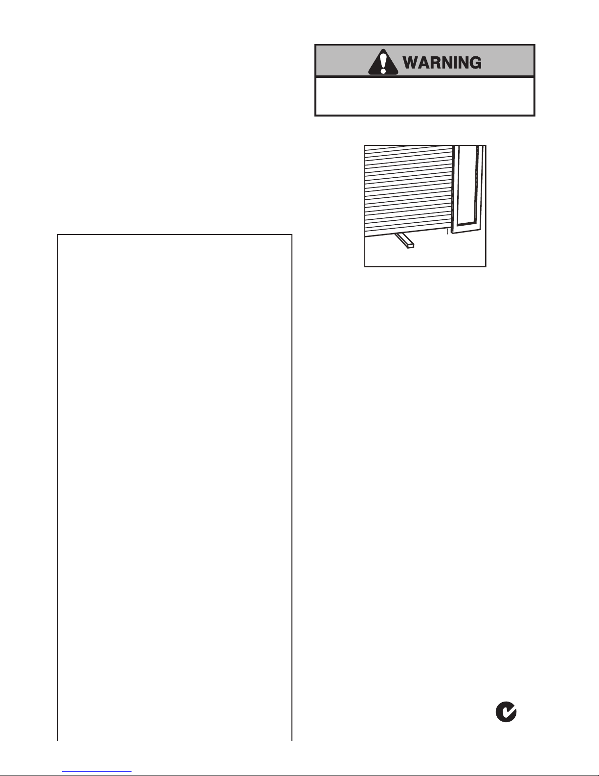
WARNING: Door may operate unexpectedly, therefore do not allow anything to stay in the path of the door.
(+) Wires
from 771ANZ
(-) Wires
from 771ANZ
(+) Wires
from 771ANZ
(-) Wires
from 771ANZ
(+) Wires
from 771ANZ
(-) Wires
from 771ANZ
(+) Wires
from 771ANZ
(-) Wires
from 771ANZ
2
Page 3
CG3800
CG3800R
White Grey
white wires
twisted together
white/black
wires twisted
together
Quick-Connect Terminals
3. To insert or release
wire, push in tab with
screwdriver tip
1. Strip wire
(10 mm)
2. Twist like colored
wires together
Grey
Red
W
hite
7/16" (10mm)
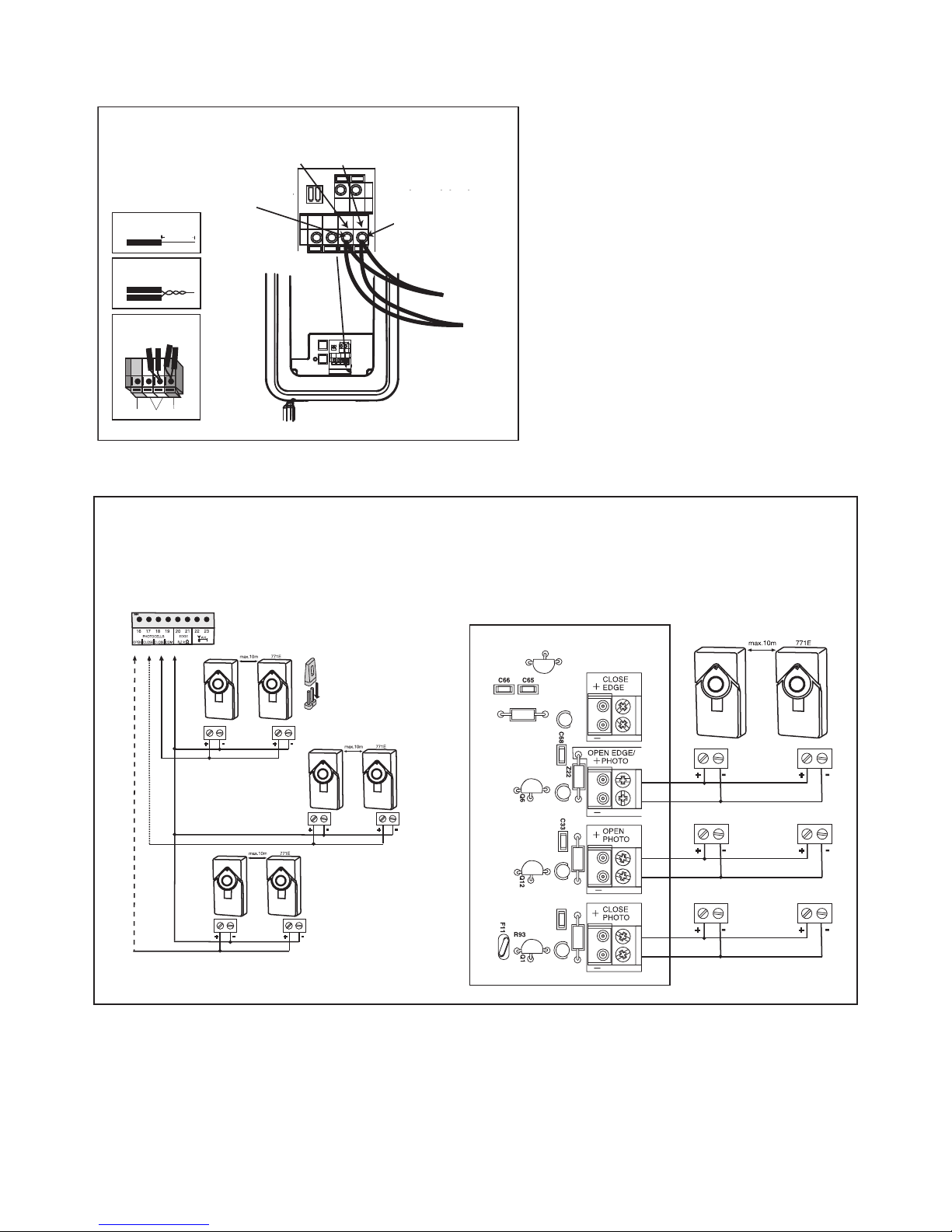
CG3800/R connections
Gently lift the cover flap at the base of the motor
t
o access the terminals. Strip all wires back about
10mm then twist the two (-) wires together, then
twist the two (+) wires together.. Trim the twisted
wires to approximately 6mm. Use a small screwd
river or pen to hold down the spring terminals,
insert the (+) wires into the grey terminal, then term
inate the (-) wires into the white terminal.
Close Beam (approx 200mm)
Close Beam (approx 700mm)
Open beam any height
Jumper must be installed.
see Installation manual for
details
Close Beam (approx 200mm)
Open beam any height
Aligning and Testing the beams
• Plug in the opener. If your opener has the Multi-Function Door Control, make sure the Lock Feature is off. Red indicator lights in both the sending and receiving eyes will glow if wiring connections and alignment are correct.
If the indicator lights are blinking (and the invisible light beam path is not obstructed), alignment is required.
• Loosen the receiving eye wing nut to allow slight rotation of unit. Adjust sensor vertically and/or horizontally until the
red indicator light glows.
• When indicator lights are glowing in both units, tighten the wing nut in the receiving eye unit.
Wiring Connections GRIFCO CG3800/R
Wiring Connections Merlin Professional Gate Motors
CB22 Control Board
Merlin Professional sliding gate motors.
CB12 Control Board
Merlin Professional Swing Gate..
(-) Wires
from 771ANZ
(+) Wires
from 771ANZ
3
Page 4
•
Press the remote control push button to open the door.
• Place an object large enough to obstruct the sensor
beam in the path of the door.
• Press the remote control push button to close the door.
T
he door will not move more than 40mm.
The door opener will not close from a remote control
i
f the indicator light in either sensor is blinking (alerting you to the fact that the sensor is misaligned or
obstructed).
You can operate the door opener by disconnecting the
safety reversing sensor.
Professional service is required if the opener closes
the door when the safety beam is obstructed
.
TEST THE 771ANZ Safety Beams
TEST THE SAFETY REVERSE SYSTEM
TEST: (Garage Doors ONLY)
• Place a (40mm) obstacle laid flat on the floor, centred
under the door.
• Operate the door in the down direction. The door must
reverse on striking the obstruction.
ADJUSTMENT:
If the door stops on the obstruction, it is not travelling far
enough in the down direction.
Consult your owners manual for instruction.
Additional copies of all manuals are available from
our web site www.chamberlainanz.com.
• Increase the DOWN limit by turning the DOWN limit.
• Repeat the test.
On a sectional door, make sure limit adjustments do
not force the door arm beyond a straight up and down
position.
• When the door reverses on the (40mm) obstacle,
remove the obstruction and run the opener through 3 or
4 complete travel cycles to test adjustment.
If the door will not reverse after repeated adjustment
attempts, call for professional door service.
Failure to test and adjust the safety reverse system may
result in serious injury or death from a closing door. Repeat
this test once a month and adjust as needed.
TROUBLE SHOOTING
1. If the
sending eyeorreceiving eye
indicator light
does not glow after installation, check for:
• Electric power to the opener.
• A short in the wiring circuit. These can occur under
staples or at screw terminal connections.
• Incorrect wiring between sensors and opener.
• An open circuit, (wire break).
• Lock switch on Multi-Function Door Control Panel is
activated. Deactivate.
2. If both sensors are blinking, realign or remove
obstruction.
3. Once an infrared sensor has been installed the motor
will only operate whilst it is installed correctly.
4. If the IR sensors are damaged and cannot be
repaired:
• For residential doors, the motor can be closed using
a hard wired wall switch if installed.
• Rollers door motors, MR series may be closed using
the activation button on the base of the rolling door
motor.
• Sectional door motors, MT series you will need to
RESET the BEAM INPUT.
For ALL Gate Motors, contact your local service technician.
RESETTING THE BEAM INPUT
(Merlin Professional Model only).
Note: Chamberlain beams are fail safe for your
safety, this should only be performed when there is
no other means of closing the door. Beams should
be serviced or replaced as soon as practical to
ensure the safe operation of your motor
To reset the beam input:
* Remove all PE beam wires from the motor.
* Turn power off for 2 seconds
* Turn power on for 2 seconds
* Turn power off for 2 seconds
Turn the power back on and test your motor, it should
open and close using the remote control.
Once the door is operational perform
THE SAFE REVERSAL TEST immediately.
N2966
709311 ANZ
40mm
Chamberlain Australia Pty Ltd
PO Box 1446
Lane Cove NSW 1595
Chamberlain New Zealand Ltd
P.O. Box 100221
North Shore 0745
www.chamberlainanz.com
4
 Loading...