

Page 1
The Chamberlain Group, Inc.
845 Larch Avenue
Elmhurst, Illinois 60126-1196
www.liftmaster.com
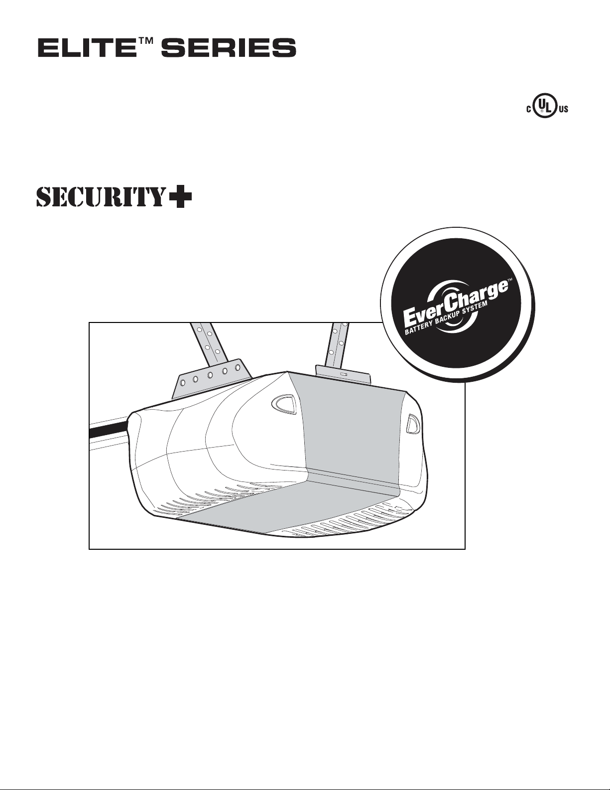
GARAGE DOOR OPENER
Model 3850
For Residential Use Only
Owner’s Manual
■ Please read this manual and the enclosed safety materials carefully!
■ Fasten the manual near the garage door after installation.
■ The door WILL NOT CLOSE unless the Protector System
®
is connected and
properly aligned.
■ Periodic checks of the opener are required to ensure safe operation.
■ The model number label is located under the light lens on the left side
panel of your opener.
®
C
o
m
p
a
t
i
b
l
e
w
i
t
h
S
e
e
P
a
g
e
2
8
f
o
r
D
e
t
a
i
l
s
Page 2
2
Introduction 2-5
Safety symbol and signal word review . . . . . . . . . . . . . .2
Preparing your garage door . . . . . . . . . . . . . . . . . . . . . . .3
Tools needed . . . . . . . . . . . . . . . . . . . . . . . . . . . . . . . . . .3
Planning . . . . . . . . . . . . . . . . . . . . . . . . . . . . . . . . . . . . .4
Carton inventory . . . . . . . . . . . . . . . . . . . . . . . . . . . . . . . .5
Hardware inventory . . . . . . . . . . . . . . . . . . . . . . . . . . . . .5
Assembly 6-7
Attach the rail to the motor unit . . . . . . . . . . . . . . . . . . . .6
Set the belt tension . . . . . . . . . . . . . . . . . . . . . . . . . . . . .6
Attach the belt cap retainer . . . . . . . . . . . . . . . . . . . . . . .7
Installation 7-22
Installation safety instructions . . . . . . . . . . . . . . . . . . . . .7
Determine the header bracket location . . . . . . . . . . . . . .8
Install the header bracket . . . . . . . . . . . . . . . . . . . . . . . .9
Attach the rail to the header bracket . . . . . . . . . . . . . . .10
Position the opener . . . . . . . . . . . . . . . . . . . . . . . . . . . .11
Hang the opener . . . . . . . . . . . . . . . . . . . . . . . . . . . . . .12
Install the control console . . . . . . . . . . . . . . . . . . . . . . .13
Install the battery backup (optional) . . . . . . . . . . . . . . . .14
Install the lights . . . . . . . . . . . . . . . . . . . . . . . . . . . . . . .14
Attach the emergency release rope and handle . . . . . .15
Electrical requirements . . . . . . . . . . . . . . . . . . . . . . . . .15
Install the Protector System
®
(Safety Sensors) . . . . .16-18
Fasten the door bracket . . . . . . . . . . . . . . . . . . . . . .19-20
Connect door arm to trolley . . . . . . . . . . . . . . . . . . .21-22
Adjustment 23-25
Program the travel limits . . . . . . . . . . . . . . . . . . . . . . . . .23
Setting the force . . . . . . . . . . . . . . . . . . . . . . . . . . . . . . .24
Test the safety reversal system . . . . . . . . . . . . . . . . . . .25
Test the Protector System
®
(Safety Sensors) . . . . . . . . .25
Operation 26-32
Operation safety instructions . . . . . . . . . . . . . . . . . . . . .26
Using your garage door opener . . . . . . . . . . . . . . . . . . .26
Using the wall-mounted control console . . . . . . . . . . . . .27
To open the door manually . . . . . . . . . . . . . . . . . . . . . . .28
Battery Backup (optional) . . . . . . . . . . . . . . . . . . . . . . . .29
Care of your garage door opener . . . . . . . . . . . . . . . . . .30
Having a problem? (Troubleshooting) . . . . . . . . . . . . . . .31
Diagnostic chart . . . . . . . . . . . . . . . . . . . . . . . . . . . . . . .32
Programming 33-34
To add or reprogram a hand-held remote control . . . . . .33
To erase all codes from motor unit memory . . . . . . . . . .33
3-Button remotes . . . . . . . . . . . . . . . . . . . . . . . . . . . . . .33
To add, reprogram or change a Keyless Entry PIN . . . .34
Repair Parts 35-36
Rail assembly parts . . . . . . . . . . . . . . . . . . . . . . . . . . . . .35
Installation parts . . . . . . . . . . . . . . . . . . . . . . . . . . . . . . .35
Motor unit assembly parts . . . . . . . . . . . . . . . . . . . . . . . .36
Accessories 37
Notes 38-39
Repair Parts and Service 40
Warranty 40
TABLE OF CONTENTS
When you see these Safety Symbols and Signal Words
on the following pages, they will alert you to the
possibility of serious injury or death if you do not
comply with the warnings that accompany them. The
hazard may come from something mechanical or from
electric shock. Read the warnings carefully.
When you see this Signal Word on the following pages, it
will alert you to the possibility of damage to your garage
door and/or the garage door opener if you do not comply
with the cautionary statements that accompany it. Read
them carefully.
INTRODUCTION
Safety Symbol and Signal Word Review
This garage door opener has been designed and tested to offer safe service provided it is installed, operated,
maintained and tested in strict accordance with the instructions and warnings contained in this manual.
Mechanical
Electrical
WARNING
WARNING
CAUTION
Page 3
3
To prevent damage to garage door and opener:
• ALWAYS disable locks BEFORE installing and operating the
opener.
• ONLY operate garage door opener at 120V, 60 Hz to avoid
malfunction and damage.
To prevent possible SERIOUS INJURY or DEATH:
• ALWAYS call a trained door systems technician if garage
door binds, sticks, or is out of balance. An unbalanced
garage door may not reverse when required.
• NEVER try to loosen, move or adjust garage door, door
springs, cables, pulleys, brackets or their hardware, ALL of
which are under EXTREME tension.
• Disable ALL locks and remove ALL ropes connected to
garage door BEFORE installing and operating garage door
opener to avoid entanglement.
Preparing your garage door
Before you begin:
• Disable locks.
• Remove any ropes connected to garage door.
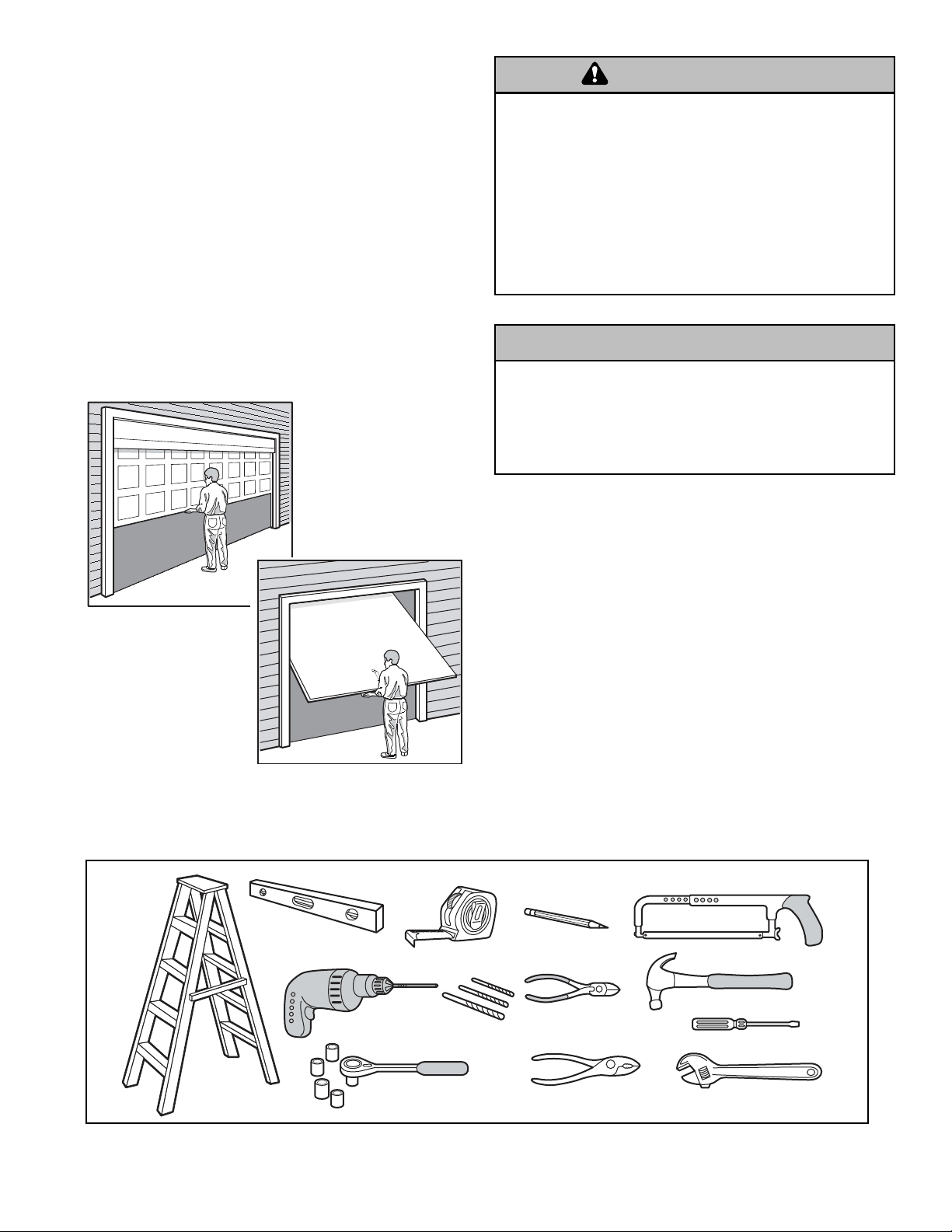
• Complete the following test to make sure your
garage door is balanced and is not sticking or binding:
1. Lift the door about halfway as shown. Release the
door. If balanced, it should stay in place, supported
entirely by its springs.
2. Raise and lower the door to see if there is any
binding or sticking.
If your door binds, sticks, or is out of balance, call a
trained door systems technician.
Tools needed
During assembly, installation and adjustment of the
opener, instructions will call for hand tools as
illustrated below.
Sectional Door
One-Piece Door
WARNING
CAUTION
Carpenter's
Level (optional)
Drill
2
1
Tape Measure
Drill Bits
3/16", 5/16"
and 5/32"
Pencil
Hack Saw
Claw Hammer
Wire Cutters
Screwdriver
Stepladder
Sockets and Wrench
1/2", 5/8", 7/16", 9/16"
and 1/4"
Pliers
Adjustable End Wrench
Page 4
4
SECTIONAL DOOR INSTALLATION
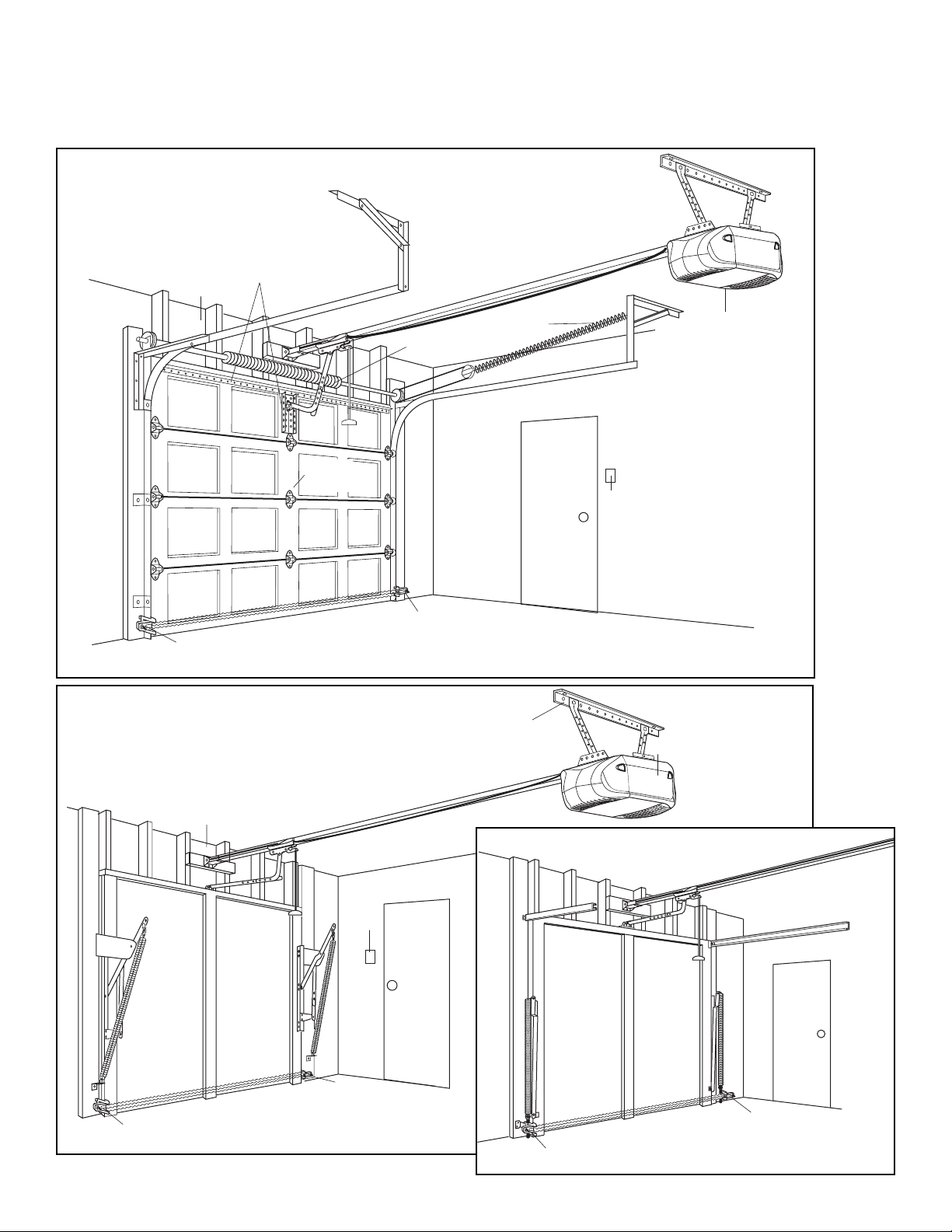
Planning
Identify the type and height of your garage door. Survey your garage area to see if any of the conditions below apply to
your installation. Additional materials may be required. You may find it helpful to refer back to this page and the
accompanying illustrations as you proceed with the installation of your opener.
ONE-PIECE DOOR WITHOUT TRACK
ONE-PIECE DOOR WITH TRACK
Horizontal and vertical reinforcement
is needed for lightweight garage doors
(fiberglass, steel, aluminum, door with
glass panels, etc.). See page 19 for details.
Header Wall
— — — — — — — —
Vertical
Centerline
of Door
Gap between floor and bottom
Safety
Reversing Sensor
of door must not exceed 1/4" (6 mm)
Torsion
Spring
Safety
Reversing Sensor
OR
Extension
Spring
FINISHED CEILING
Support bracket &
fastening hardware
is required.
See page 12.
Motor Unit
Access
Door
Wallmounted
Door
Control
Header
Wall
Gap between floor and bottom of
Safety
Reversing Sensor
door must not exceed 1/4" (6 mm)
Wallmounted
Door
Control
Safety
Reversing Sensor
Access
Door
FINISHED CEILI
Support
bracket
& fastening
hard
ware is re
See page 12.
NG
quired.
Safety Reversing Sensor
Motor Unit
Access
Door
Safety Reversing Sensor
Gap between floor and bottom of door
must not exceed 1/4" (6 mm).
Page 5
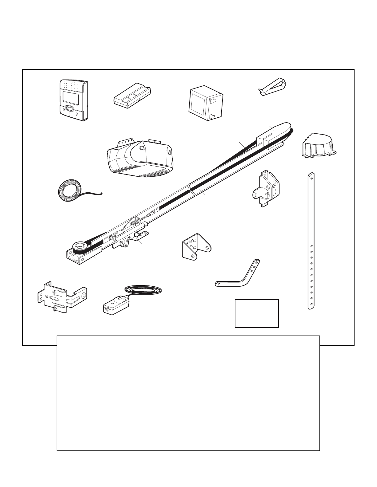
5
Your garage door opener is packaged in two cartons
which contain the motor unit and all parts illustrated
below. Accessories will depend on the model purchased.
If anything is missing, carefully check the packing
material. Parts may be stuck in the foam. Hardware for
installation is also listed below.
Carton Inventory
INSTALLATION HARDWARE
Hex Bolt 5/16"-18x7/8" (4)
Hex Screw #8 x 3/8" (2)
Lag Screw 5/16"-9x1-5/8" (2)
Lag Screw 5/16"-18x1-7/8" (2)
Clevis Pin 5/16"x2-3/4" (1)
Clevis Pin 5/16"x1-1/4" (1)
Clevis Pin 5/16"x1" (1)
Nut 5/16"-18 (4)
Lock Washer 5/16" (4)
Screw 6ABx1-1/4" (2)
Self-Threading Screw 1/4"-14x5/8" (2)
Screw 6-32x1" (2)
Insulated Staples (30)
Ring Fastener (3)
Dry Wall Anchors (2)
Rope
Handle
Rail Grease
Carriage Bolt 1/4"-20x1/2" (2)
Wing Nut 1/4"-20 (2)
L
O
C
K
L
IGH
T
LCD Motion Detecting
Door Control Console
2-Conductor Bell Wire
White & White/Red
SECURITY✚
3-Button Remote Control
Motor Unit w/Light Lenses
®
Remote Control
Visor Clip
Styrofoam
Battery
(Optional)
Belt
Belt Cap Retainer
One-Piece
Rail
Door Bracket
Belt
Pulley Bracket
Safety Sensor
Bracket (2)
Y
L
N
T O
N
U
O
M
G
IN
IL
E
C
P
Trolley
U
Header Bracket
The Protector System
®
(2) Safety Reversing Sensors
(1 Sending Eye and 1 Receiving Eye)
with 2-Conductor White & White/Black
Bell Wire attached
Curved Door
Arm Section
Safety Labels
and
Literature
Straight Door
Arm Section
Page 6
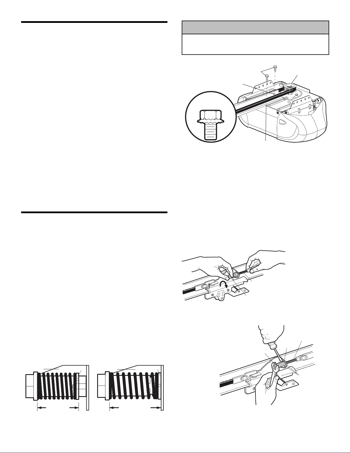
6
ASSEMBLY STEP 1
Attach the Rail to the Motor Unit
To avoid installation difficulties, do not run the
garage door opener until instructed to do so.
• Remove the two washered bolts mounted on top of
motor unit.
• Align rail and styrofoam over belt pulley. Cut tape from
rail, chain and styrofoam.
• REMOVE STYROFOAM.
• Insert both washered bolts through the rail into the
motor unit. Tighten bolts securely.
Use only these bolts! Use of any other bolts will
cause serious damage to door opener.
• Position belt over the motor unit belt pulley.
To avoid SERIOUS damage to opener, ONLY use bolts
mounted in top of motor unit.
ASSEMBLY STEP 2
Set the Belt Tension
• By hand, thread the spring trolley nut on the threaded
shaft until it is finger tight against the trolley (Figure 1).
Do not use any tools.
• Insert a screwdriver tip into one of the nut ring slots
and brace it firmly against the trolley (Figure 2).
• Place a 7/16" open end wrench on the square
end. Rotate about 1/4 turn until the spring releases
and snaps the nut ring against the trolley (Figure 3).
This extends the spring for optimum belt tension.
Figure 1
Figure 2
Figure 3
CAUTION
USE ONLY THIS
TYPE AND SIZE
BOLT
Washered Bolt
5/16"-18x1/2"
Rail Hole
Rail Hole
Motor U
Belt Pulley
nit
Trolley
Nut Ring Trolley
Nut Ring
Trolley
Threaded
Shaft
Spring/Trolley Nut
Square
End
Nut
Ring
Trolley
Threaded
Shaft
Nut Ring
Slots
BEFORE AFTER RELEASE
1" (2.5 cm) 1-1/4" (3.18 cm)
Page 7
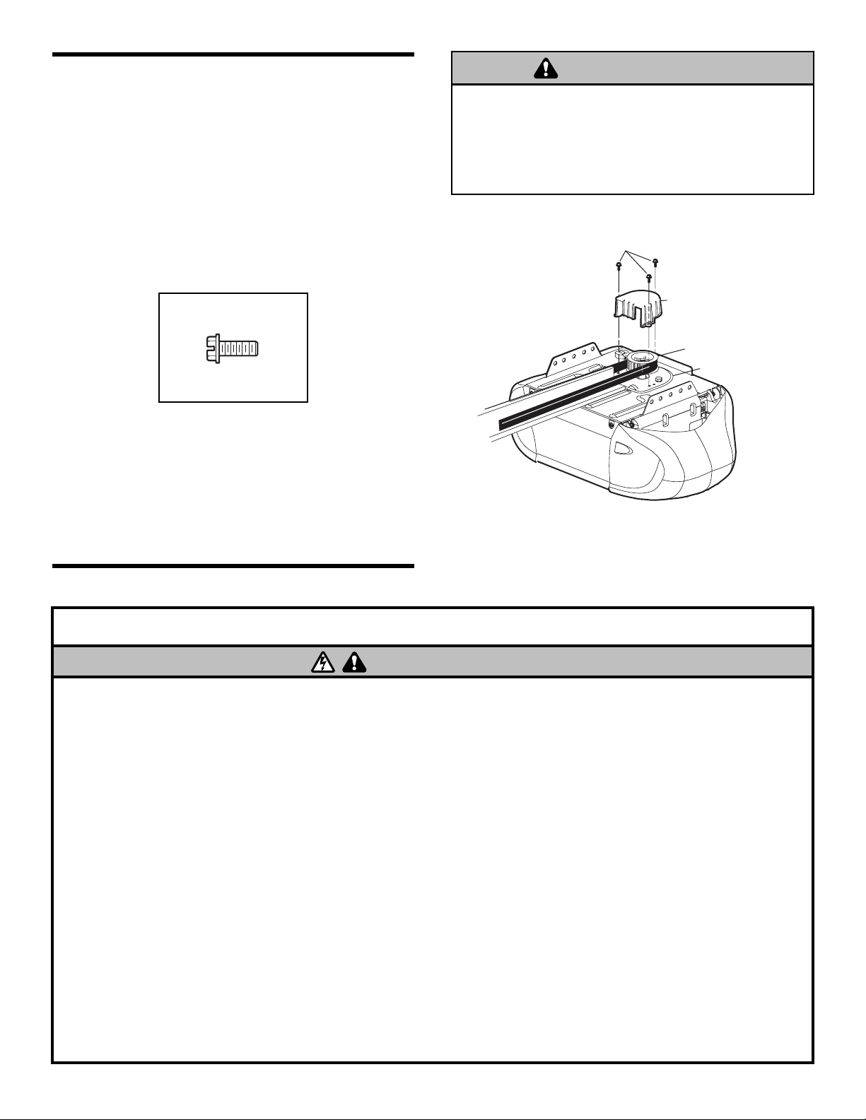
7
ASSEMBLY STEP 3
Attach the Belt Cap Retainer
• Position the belt cap retainer over the motor unit belt
pulley so the three holes in cap align with the three
holes in mounting plate. Attach with #8x3/8" hex
screws provided.
You have now finished assembling your garage door
opener. Please read the following warnings before
proceeding to the installation section.
INSTALLATION
To avoid possible SERIOUS INJURY to fingers from moving
garage door opener:
• ALWAYS keep hand clear of belt pulley while operating
opener.
• Securely attach belt pulley cover BEFORE operating.
HARDWARE SHOWN
ACTUAL SIZE
IMPORTANT INSTALLATION INSTRUCTIONS
To reduce the risk of SEVERE INJURY or DEATH:
1. READ AND FOLLOW ALL INSTALLATION WARNINGS AND
INSTRUCTIONS.
2. Install garage door opener ONLY on properly balanced and
lubricated garage door. An improperly balanced door may
not reverse when required and could result in SEVERE
INJURY or DEATH.
3. ALL repairs to cables, spring assemblies and other
hardware MUST be made by a trained door systems
technician BEFORE installing opener.
4. Disable ALL locks and remove ALL ropes connected to
garage door BEFORE installing opener to avoid
entanglement.
5. Install garage door opener 7 feet (2.1 m) or more above
floor.
6. Mount emergency release handle 6 feet (1.8 m) above floor.
7. NEVER connect garage door opener to power source until
instructed to do so.
8. NEVER wear watches, rings or loose clothing while
installing or servicing opener. They could be caught in
garage door or opener mechanisms.
9. Install wall-mounted garage control console:
• within sight of the garage door.
• out of reach of children at minimum height of
5 feet (1.5 m).
• away from ALL moving parts of the door.
10. Place entrapment warning label on wall next to garage
control console.
11. Place manual release/safety reverse test label in plain view
on inside of garage door.
12. Upon completion of installation, test safety reversal
system. Door MUST reverse on contact with a 1-1/2"
(3.8 cm) high object (or a 2x4 laid flat) on the floor.
13. To avoid SERIOUS PERSONAL INJURY or DEATH from
electrocution, disconnect ALL electric and battery power
BEFORE performing ANY service or maintenance.
WARNING
8x3/8" Hex Screws
Hex Screw
#8x3/8"
Belt Cap Retainer
Motor Unit Belt Pulley
Mounting Plate
WARNING
Page 8

8
INSTALLATION STEP 1
Determine the Header Bracket
Location
Installation procedures vary according to garage door
types. Follow the instructions which apply to your door.
1. Close the door and mark the inside vertical centerline
of the garage door.
2. Extend the line onto the header wall above the door.
You can fasten the header bracket within 4 feet
(1.22 m) of the left or right of the door center only
if a torsion spring or center bearing plate is in the
way; or you can attach it to the ceiling (see page 9)
when clearance is minimal. (It may be mounted on
the wall upside down if necessary, to gain
approximately 1/2" (1 cm).)
If you need to install the header bracket on a 2x4
(on wall or ceiling), use lag screws (not provided)
to securely fasten the 2x4 to structural supports as
shown here and on page 9.
3. Open your door to the highest point of travel as shown.
Draw an intersecting horizontal line on the header wall
above the high point:
• 2" (5 cm) above the high point for sectional door
and one-piece door with track.
• 8" (20 cm) above the high point for one-piece door
without track.
This height will provide travel clearance for the top
edge of the door.
NOTE: If the total number of inches exceeds the
height available in your garage, use the maximum
height possible, or refer to page 9 for ceiling
installation.
To prevent possible SERIOUS INJURY or DEATH:
• Header bracket MUST be RIGIDLY fastened to structural
support on header wall or ceiling, otherwise garage door
might not reverse when required. DO NOT install header
bracket over drywall.
• Concrete anchors MUST be used if mounting header
bracket or 2x4 into masonry.
• NEVER try to loosen, move or adjust garage door, springs,
cables, pulleys, brackets, or their hardware, ALL of which
are under EXTREME tension.
• ALWAYS call a trained door systems technician if garage
door binds, sticks, or is out of balance. An unbalanced
garage door might not reverse when required.
WARNING
Header Wall
Header Wall
2" (5 cm)
Highest Point
of Travel
Door
Sectional door with curved track
Header Wall
Door
Jamb
Hardware
8" (20 cm)
Highest
Point
of Travel
Track
Unfinished
Ceiling
2x4
Vertical Centerline
of Garage Door
2x4
Level
(optional)
Header Wall
Door
One-piece door with horizontal track
Header Wall
8" (20 cm)
Door
OPTIONAL
CEILING
MOUNT
FOR
HEADER
BRACKET
Structural
Supports
2" (5 cm)
Highest Point
of Travel
Highest
Point
of Travel
Track
One-piece door without track:
jamb hardware
Pivot
One-piece door without track:
pivot hardware
Page 9
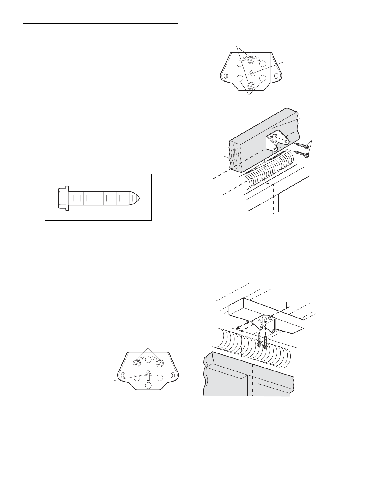
9
INSTALLATION STEP 2
Install the Header Bracket
You can attach the header bracket either to the wall
above the garage door, or to the ceiling. Follow the
instructions which will work best for your particular
requirements. Do not install the header bracket over
drywall. If installing into masonry, use concrete
anchors (not provided).
WALL HEADER BRACKET INSTALLATION
• Center the bracket on the vertical centerline with the
bottom edge of the bracket on the horizontal line as
shown (with the arrow pointing toward the ceiling).
• Mark the vertical set of bracket holes (do not use the
holes designated for ceiling mount). Drill 3/16" pilot
holes and fasten the bracket securely to a structural
support with the hardware provided.
HARDWARE SHOWN ACTUAL SIZE
UP
CEILING MOUNT ONLY
Ceiling Mounting Holes
The nail hole is for
positioning only.
You must use lag screws
to mount the header bracket.
U
P
Lag Screws
5/16"-9x1-5/8"
Garage Door
Vertical
Centerline
of Garage Door
Header Wall
– Finished Ceiling –
Header
Bracket
6" (15 cm)
Maximum
Vertical
Centerline
of Garage Door
Door
Spring
CEILING HEADER BRACKET INSTALLATION
• Extend the vertical centerline onto the ceiling as
shown.
• Center the bracket on the vertical mark, no more than
6" (15 cm) from the wall. Make sure the arrow is
pointing toward the wall. The bracket can be mounted
flush against the ceiling when clearance is minimal.
• Mark the side holes. Drill 3/16" pilot holes and fasten
bracket securely to a structural support with the
hardware provided.
Wall Mounting Holes
Lag Screw
5/16"-9x1-5/8"
CEILING MOUNT ONLY
Optional
Wall Mounting Holes
Header
Wall
2x4
Structural
Support
Horizontal
Line
Highest Point of
Garage Door Travel
UP
Header
Bracket
The nail hole is for
positioning only.
You must use lag screws
to mount the header bracket.
Vertical
Centerline of
Garage Door
Y
NL
T O
N
U
O
M
G
IN
IL
E
C
UP
Door Spring
Garage
Door
Vertical
Centerline of
Garage Door
Lag Screws
5/16"-9x1-5/8"
Page 10
10
Header Wall
HARDWARE SHOWN ACTUAL SIZE
INSTALLATION STEP 3
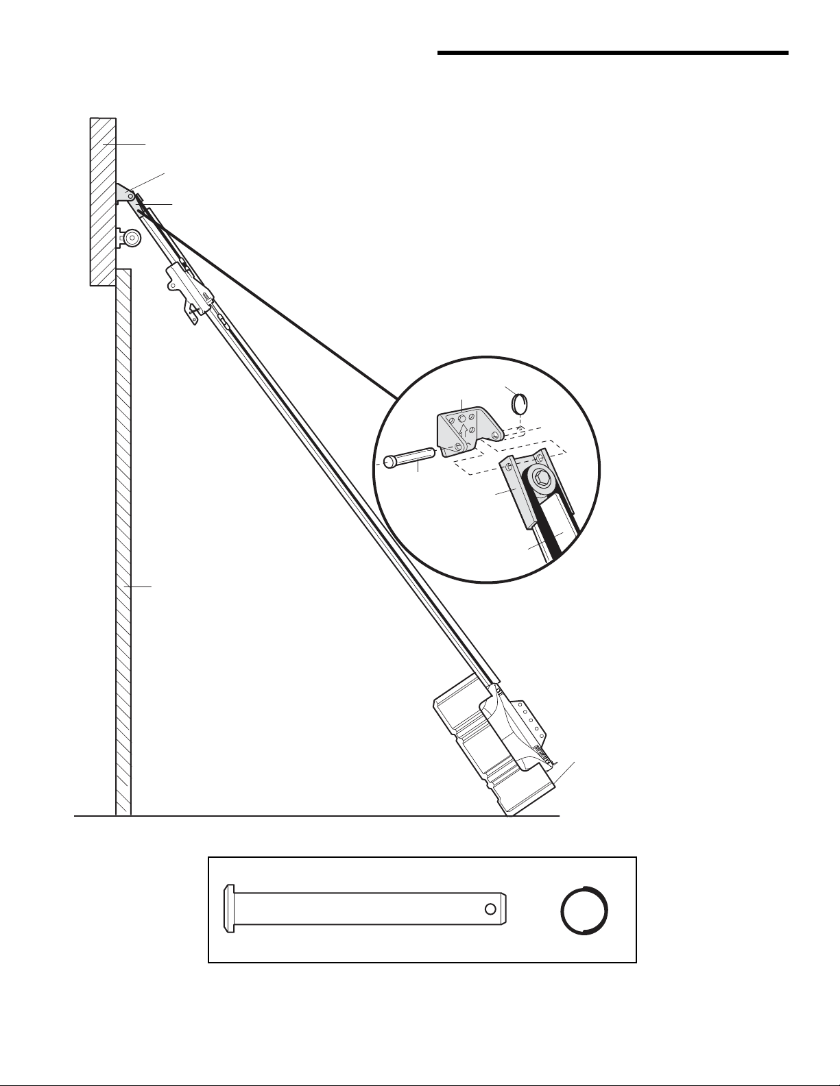
Attach the Rail to the Header Bracket
• Position the opener on the garage floor below the
header bracket. Use packing material as a protective
base. NOTE: If the door spring is in the way you’ll
need help. Have someone hold the opener securely
on a temporary support to allow the rail to clear
the spring.
• Position the rail bracket against the header bracket.
• Align the bracket holes and join with a clevis pin
as shown.
• Insert a ring fastener to secure.
Header
Bracket
Belt Pulley
Bracket
Ring
Header
Bracket
Fastener
Garage
Door
Clevis Pin
5/16"x2-3/4"
Belt Pulley
Bracket
Rail
Temporary
Support
Clevis Pin
5/16"x2-3/4"
Ring Fastener
Page 11
11
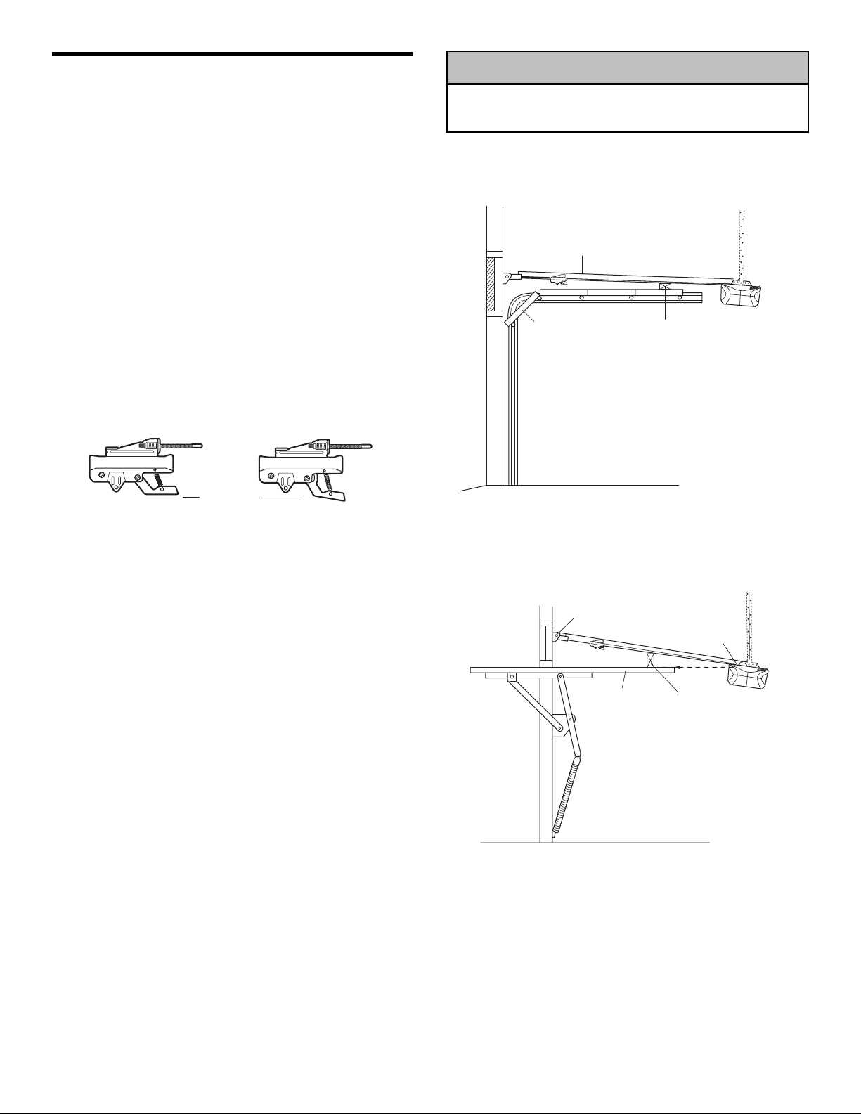
ONE-PIECE DOOR WITHOUT TRACK
• With the door fully open and parallel to the floor,
measure the distance from the floor to the top of the
door.
• Using a stepladder as a support, raise the top of the
opener to this height.
• The top of the door should be level with the top of the
motor unit. Do not position the opener more than
4" (10 cm) above this point.
INSTALLATION STEP 4
Position the Opener
Follow instructions which apply to your door type as
illustrated.
SECTIONAL DOOR OR ONE-PIECE DOOR WITH
TRACK
A 2x4 laid flat is convenient for setting an ideal
door-to-rail distance.
• Raise the opener onto a stepladder. You will need help
at this point if the ladder is not tall enough.
• Open the door all the way and place a 2x4 laid flat on
the top section beneath the rail.
• If the top section or panel hits the trolley when you
raise the door, pull down on the trolley release arm
to disconnect inner and outer sections. Slide the outer
trolley toward the motor unit. The trolley can remain
disconnected until Installation Step 12 is completed.
To prevent damage to garage door, rest garage door opener
rail on 2x4 placed on top section of door.
CAUTION
Rail
Door
2x4 is used to determine
the correct mounting height
from ceiling.
Trolley
Release Arm
ENGAGED
RELEASED
Header
Bracket
Top of Door
Top of Motor Unit
2x4 is used to determine
the correct mounting height
from ceiling.
Page 12
12
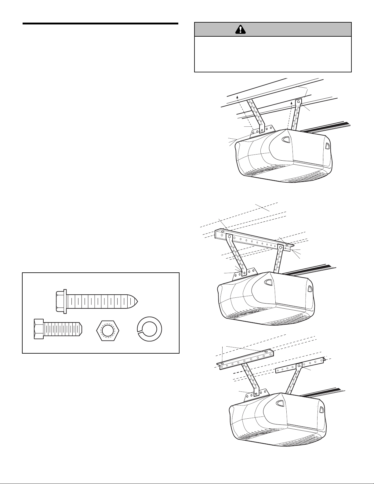
INSTALLATION STEP 5
Hang the Opener
Three representative installations are shown. Yours may
be different. Hanging brackets should be angled
(Figure 1) to provide rigid support. On finished ceilings
(Figure 2 and Figure 3), attach a sturdy metal bracket to
structural supports before installing the opener. This
bracket and fastening hardware are not provided.
1. Remove foam packaging. Measure the distance from
each side of the motor unit to the structural support.
2. Cut both pieces of the hanging bracket to required
lengths.
3. Drill 3/16" pilot holes in the structural supports.
4. Attach one end of each bracket to a support with
5/16"-18x1-7/8" lag screws.
5. Fasten the opener to the hanging brackets with
5/16"-18x7/8" hex bolts, lock washers and nuts.
6. Check to make sure the rail is centered over the door
(or in line with the header bracket if the bracket is not
centered above the door).
7. Remove the 2x4. Operate the door manually. If the
door hits the rail, raise the header bracket.
8. Grease the top and underside of the rail surface where
the trolley slides with rail grease.
NOTE: DO NOT connect power to opener at this time.
To avoid possible SERIOUS INJURY from a falling garage
door opener, fasten it SECURELY to structural supports of
the garage. Concrete anchors MUST be used if installing ANY
brackets into masonry.
HARDWARE SHOWN ACTUAL SIZE
Figure 1
Figure 2
Figure 3
WARNING
Structural
Bolt 5/16"-18x7/8"
Lock Washer 5/16"
Nut 5/16"-18
Bracket
(Not Provided)
Measure
Distance
Hidden
Support
— FINISHED CEILING —
Lag Screws
5/16"-18x1-7/8"
Supports
Lag Screws
5/16"-18x1-7/8"
Lag Screw 5/16"-9x1-5/8"
Hex Bolt
5/16"-18x7/8"
Nut 5/16"-18
Lock Washer 5/16"
Bolt 5/16"-18x7/8"
Lock Washer 5/16"
Nut 5/16"-18
Lag Screws
5/16"-18x1-7/8"
Bolt 5/16"-18x7/8"
Lock Washer 5/16"
Nut 5/16"-18
(Not Provided)
Bolt 5/16"-18x7/8"
Lock Washer 5/16"
Nut 5/16"-18
FINISHED CEILING
(Not Provided)
Bolt 5/16"-18x7/8"
Lock Washer 5/16"
Nut 5/16"-18
Page 13
13
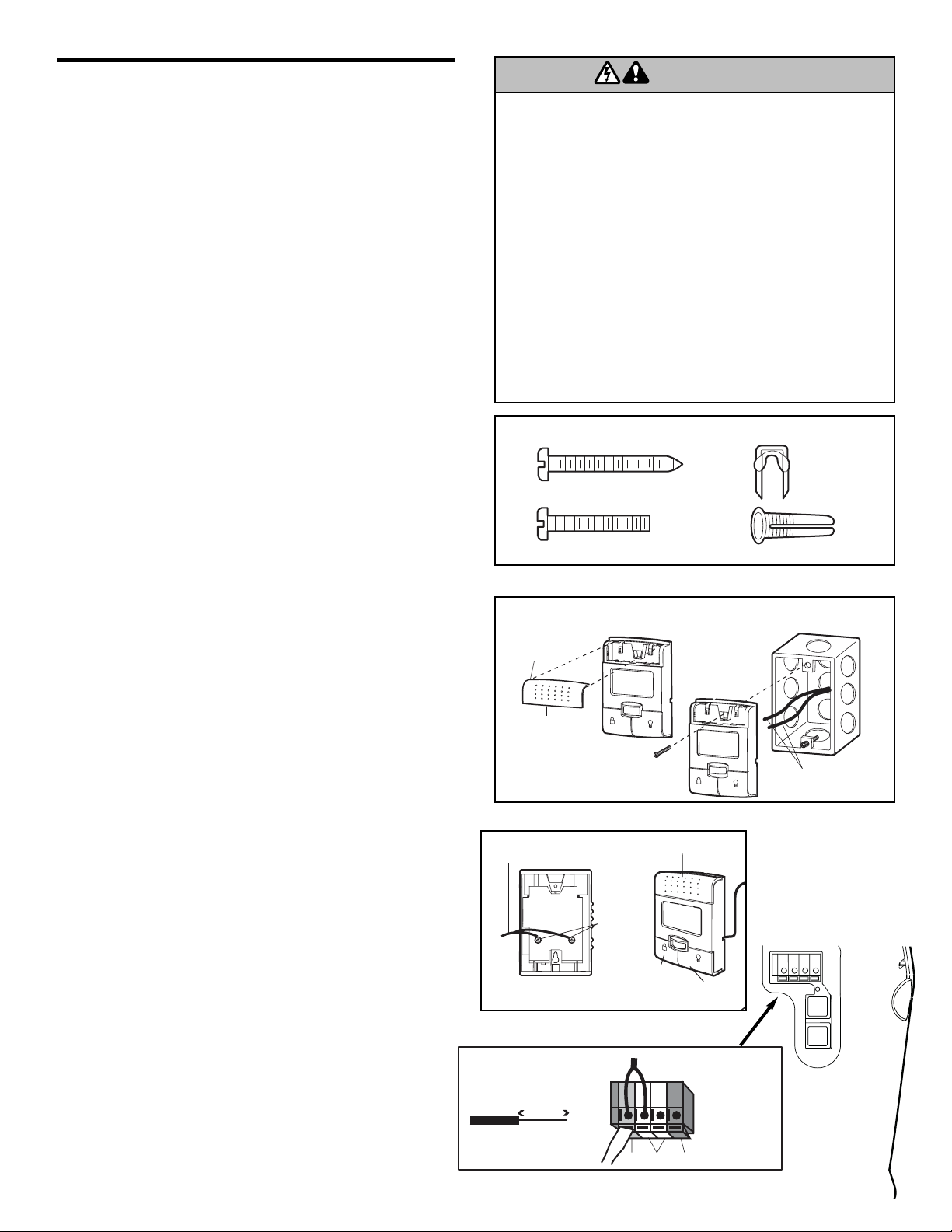
INSTALLATION STEP 6
Install the Control Console
HARDWARE SHOWN ACTUAL SIZE
Locate control console within sight of door, at a minimum
height of 5' (1.5 m) where small children cannot reach,
away from moving parts of door and door hardware. If
installing into drywall, drill 5/32" holes and use the
anchors provided. For pre-wired installations (as in new
home construction), it may be mounted to a single gang
box (Figure 1).
NOTE: The functional temperature range of the control
console is between -4° F (-20° C) and 122° F (50° C).
Scroll speed of display is slower at lower temperatures
although the control console remains fully functional.
CAUTION: Continuous exposure of the control console
to temperatures below -22° F (-30° C) may damage the
LCD screen.
SPECIAL NOTE: Only one 398LM can be connected to
each garage door opener. If additional wall controls are
desired to operate the same garage door opener, it is
recommended to use model 378LM wireless wall control
as the secondary control console.
1. Strip 7/16" (11 mm) of insulation from one end of bell
wire and connect to the two screw terminals on back of
control console by color: white wire to the W (2) and
white/red wire to the R (1) (Figure 2).
2. Remove push bar cover by gently prying at the
lower/middle portion of the cover with a small flat-head
screwdriver. Fasten with 6AB x 1-1/4" self-tapping
screws (drywall installation) or 6-32 x 1" machine
screws
(into gang box) as follows:
• Install bottom screw, allowing 1/8" (3 mm) to protrude
above wall surface.
• Position bottom of control console on screw head
and slide down to secure. Adjust screw for snug fit.
• Drill and install top screw with care to avoid cracking
plastic housing. Do NOT overtighten.
• Replace cover by inserting top tabs first and then
snap cover in place.
3. (For standard installations ONLY) Run bell wire up
wall and across ceiling to motor unit. Use insulated
staples to secure wire in several places. Do NOT
pierce wire with a staple, creating a short or open
circuit.
4. Strip 7/16" (11 mm) of insulation from end of bell wire.
Connect bell wire to the quick-connect terminals on the
motor unit: white to white and white/red to red (Figure
2).
NOTE: If you have any trouble with the operation of the
buttons, loosen the top mounting screw.
NOTE: DO NOT connect power and operate the opener
at this time.The trolley will travel to the full open position
but will not return to the close position until the sensor
beam is connected and properly aligned.
Push Bar
Light
Button
Lock
Button
Door
Control
Terminal
Screws
(BACK VIEW)
W
2
R
1
2-Conductor
Bell Wire
L
O
C
K
L
O
C
K
To prevent possible SERIOUS INJURY or DEATH from
electrocution:
• Be sure power is NOT connected BEFORE installing door
control.
• Connect ONLY to 24 VOLT low voltage wires.
To prevent possible SERIOUS INJURY or DEATH from a
closing garage door:
• Install door control within sight of garage door, out of reach
of children at a minimum height of 5' (1.5 m), and away
from ALL moving parts of door.
• NEVER permit children to operate or play with door control
push buttons or remote control transmitters.
• Activate door ONLY when it can be seen clearly, is properly
adjusted and there are no obstructions to door travel.
• ALWAYS keep garage door in sight until completely closed.
NEVER permit anyone to cross path of closing garage door.
Figure 2
Figure 1
WARNING
Screw 6ABx1-1/4"
(std installation)
Screw 6-32x1"
(pre-wired)
REMOVE & REPLACE COVER
To Replace Insert
Top Tabs First
Push Bar Cover
Control Console Connections
Strip wire 7/16" (11 mm)
7/16" (11 mm)
LOCK
L
I
G
HT
To release wire, push in
tab with screwdriver tip
Red GreyWhite
LOCK
PRE-WIRED INSTALLATION
L
I
G
HT
Insulated
Staples
Drywall Anchors
24 Volt Bell Wire
Page 14
14
INSTALLATION STEP 7
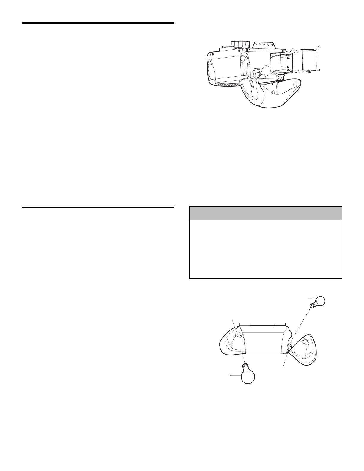
Install the Battery Backup (Optional)
• Make sure motor unit is unplugged.
• Using a Phillips head screwdriver, remove the battery
cover on the motor unit.
• Partially insert battery into motor unit with terminals
facing out.
• Connect red (+) and black (-) wires from motor unit to
corresponding terminals on battery.
• Replace battery cover.
INSTALLATION STEP 8
Install the Lights
• Press the release tabs on both sides of lens. Gently
rotate lens back and downward until the lens hinge is
in the fully open position. Do not remove the lens.
• Install a 100 watt maximum light bulb in each socket.
Light bulb size should be A19, standard neck only. The
lights will turn ON and remain lit for approximately 41/2 minutes when power is
connected. Then the lights will turn OFF.
• Reverse the procedure to close the lens.
• Use A19, standard neck garage door opener bulbs for
replacement.
NOTE: Use only standard light bulbs. The use of short
neck or speciality light bulbs may overheat the endpanel
or light socket.
To prevent possible OVERHEATING of the endpanel or light
socket:
• DO NOT use short neck or specialty light bulbs.
• DO NOT use halogen bulbs. Use ONLY incandescent.
To prevent damage to the opener:
• DO NOT use bulbs larger than 100W.
• ONLY use A19 size bulbs.
Battery
Battery Cover
CAUTION
100 Watt (Max)
Standard Light Bulb
Release Tab
Lens
100 Watt (Max)
Standard Light Bulb
Hinge
Page 15
15
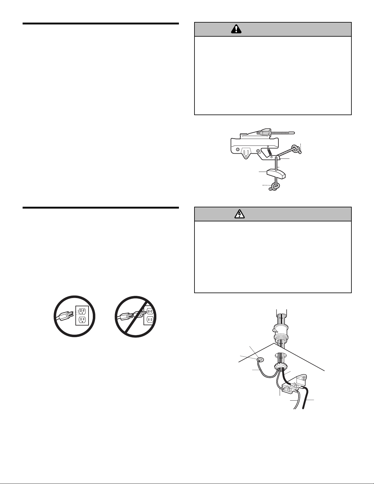
INSTALLATION STEP 10
Electrical Requirements
To avoid installation difficulties, do not run the
opener at this time.
To reduce the risk of electric shock, your garage door
opener has a grounding type plug with a third grounding
pin. This plug will only fit into a grounding type outlet. If
the plug doesn’t fit into the outlet you have, contact a
qualified electrician to install the proper outlet.
If permanent wiring is required by your local code,
refer to the following procedure.
To make a permanent connection through the 7/8" (2 cm)
hole in the top of the motor unit:
• Remove the motor unit cover screws and set the cover
aside.
• Remove the attached 3-prong cord.
• Connect the black (line) wire to the screw on the brass
terminal; the white (neutral) wire to the screw on the
silver terminal; and the ground wire to the green
ground screw. The opener must be grounded.
• Reinstall the cover.
To avoid installation difficulties, do not run the
opener at this time.
To prevent possible SERIOUS INJURY or DEATH from
electrocution or fire:
• Disconnect ALL electric and battery power BEFORE
performing ANY service or maintenance.
• Garage door installation and wiring MUST be in compliance
with ALL local electrical and building codes.
• NEVER use an extension cord, 2-wire adapter, or change
plug in ANY way to make it fit outlet. Be sure the opener
is grounded.
INSTALLATION STEP 9
Attach the Emergency Release Rope
and Handle
• Thread one end of the rope through the hole in the top
of the red handle so “NOTICE” reads right side up as
shown. Secure with an overhand knot at least
1" (2.5 cm) from the end of the rope to prevent
slipping.
• Thread the other end of the rope through the hole in
the release arm of the outer trolley.
• Adjust rope length so the handle is 6 feet (1.8 m)
above the floor. Ensure that the rope and handle clear
the tops of all vehicles to avoid entanglement. Secure
with an overhand knot.
NOTE: If it is necessary to cut the rope, heat seal the cut
end with a match or lighter to prevent unraveling.
To prevent possible SERIOUS INJURY or DEATH from a
falling garage door:
• If possible, use emergency release handle to disengage
trolley ONLY when garage door is CLOSED. Weak or broken
springs or unbalanced door could result in an open door
falling rapidly and/or unexpectedly.
• NEVER use emergency release handle unless garage
doorway is clear of persons and obstructions.
• NEVER use handle to pull door open or closed. If rope knot
becomes untied, you could fall.
WARNING
Overhand
Knot
Trolley
Emergency
Release Handle
Overhand
Knot
NOTICE
Rope
Release
Arm
RIGHT
WRONG
WARNING
PERMANENT WIRING
CONNECTION
Ground Tab
Green
Ground Screw
Ground Wire
White Wire
Black
Wire
Black Wire
Page 16
16
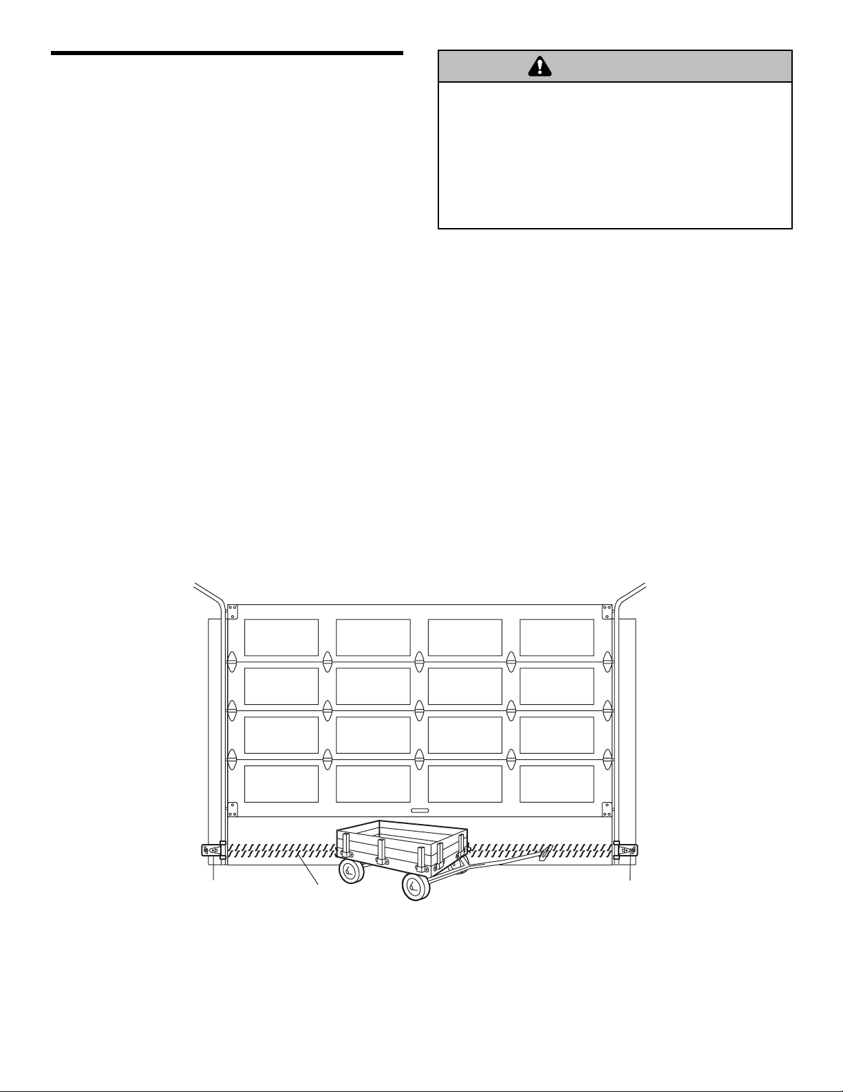
Facing the door from inside the garage
INSTALLATION STEP 11
Install The Protector System
®
The safety reversing sensor must be connected and
aligned correctly before the garage door opener will
move in the down direction.
IMPORTANT INFORMATION ABOUT
THE SAFETY REVERSING SENSOR
When properly connected and aligned, the sensor will
detect an obstacle in the path of its electronic beam. The
sending eye (with an amber indicator light) transmits an
invisible light beam to the receiving eye (with a green
indicator light). If an obstruction breaks the light beam
while the door is closing, the door will stop and reverse
to full open position, and the opener lights will flash 10
times.
The units must be installed inside the garage so that the
sending and receiving eyes face each other across the
door, no more than 6" (15 cm) above the floor. Either can
be installed on the left or right of the door as long as the
sun never shines directly into the receiving eye lens.
The mounting brackets are designed to clip onto the
track of sectional garage doors without additional
hardware.
If it is necessary to mount the units on the wall, the
brackets must be securely fastened to a solid surface
such as the wall framing. Extension brackets (see
accessories) are available if needed. If installing in
masonry construction, add a piece of wood at each
location to avoid drilling extra holes in masonry if
repositioning is necessary.
The invisible light beam path must be unobstructed. No
part of the garage door (or door tracks, springs, hinges,
rollers or other hardware) may interrupt the beam while
the door is closing.
Be sure power is NOT connected to the garage door opener
BEFORE installing the safety reversing sensor.
To prevent SERIOUS INJURY or DEATH from a closing
garage door:
• Correctly connect and align the safety reversing sensor.
This required safety device MUST NOT be disabled.
• Install the safety reversing sensor so beam is NO HIGHER
than 6" (15 cm) above garage floor.
WARNING
Safety Reversing Sensor
6" (15 cm) max. above floor
Invisible Light Beam
Protection Area
Safety Reversing Sensor
6" (15 cm) max. above floor
Page 17
17
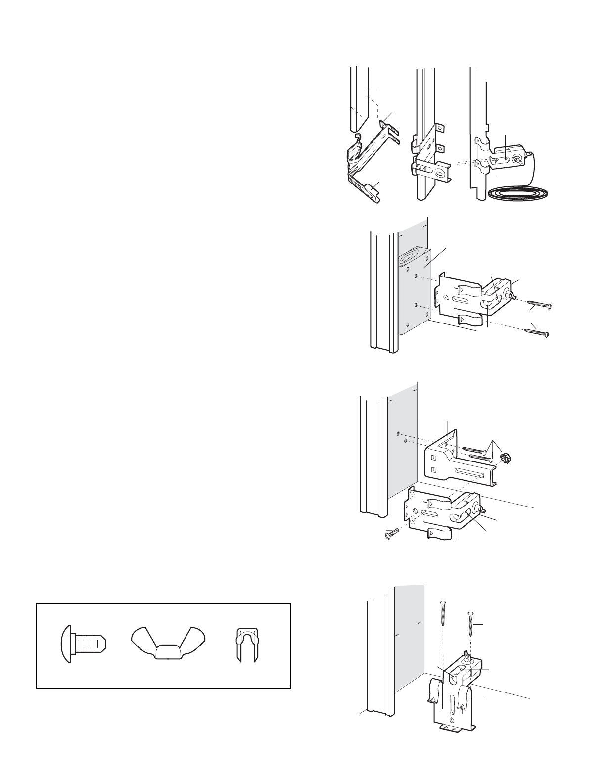
INSTALLING THE BRACKETS
Be sure power to the opener is disconnected. Install
and align the brackets so the sensors will face each
other across the garage door, with the beam no higher
than 6" (15 cm) above the floor. They may be installed in
one of three ways, as follows.
Garage door track installation (preferred):
• Slip the curved arms over the rounded edge of each
door track, with the curved arms facing the door. Snap
into place against the side of the track. It should lie
flush, with the lip hugging the back edge of the track
(Figure 1).
If your door track will not support the bracket securely,
wall installation is recommended.
Wall installation (Figure 2 & 3):
• Place the bracket against the wall with curved arms
facing the door. Be sure there is enough clearance for
the sensor beam to be unobstructed.
• If additional depth is needed, an extension bracket
(see accessories) or wood blocks can be used.
• Use bracket mounting holes as a template to locate
and drill (2) 3/16" diameter pilot holes on the wall at
each side of the door, no higher than 6" (15 cm)
above the floor.
• Attach brackets to wall with lag screws (not provided).
• If using extension brackets or wood blocks, adjust right
and left assemblies to the same distance out from the
mounting surface. Make sure all door hardware
obstructions are cleared.
Floor installation (Figure 4):
• Use wood blocks or extension brackets (see
accessories) to elevate sensor brackets so the lenses
will be no higher than 6" (15 cm) above the floor.
• Carefully measure and place right and left assemblies
at the same distance out from the wall. Be sure all
door hardware obstructions are cleared.
• Fasten to the floor with concrete anchors as shown.
HARDWARE SHOWN ACTUAL SIZE
Figure 1
Figure 2
Figure 3
DOOR TRACK MOUNT (RIGHT SIDE)
Door
Track
Lip
Sensor
Bracket
WALL MOUNT (RIGHT SIDE)
l
Fasten Wood Block to Wall with
Lag Screws (Not Provided)
WALL MOUNT (RIGHT SIDE)
Extension
Bracket
(See Accessories)
Inside
arage
G
al
W
Inside
arage
G
al
W
l
Indicator
Light
Lens
Indicator
Light
Lens
(Provided with
Extension Bracket)
Sensor
Bracket
Lag Screws
(Not Provided)
Carriage Bolt
1/4"-20x1/2"
Wing Nut
1/4"-20
Staples
(Provided with
Extension
Bracket)
Figure 4
Inside
arage
G
al
W
Sensor
Bracket
Indicator
Light
Lens
FLOOR MOUNT (RIGHT SIDE)
Attach with
Concrete Anchors
l
Lens
(Not Provided)
Indicator
Light
Sensor
Bracket
Page 18
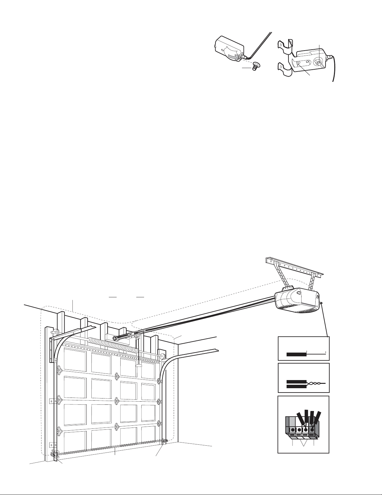
18
Figure 5MOUNTING AND WIRING THE SAFETY
REVERSING SENSORS
• Slide a 1/4"-20x1/2" carriage bolt head into the slot on
each sensor. Use wing nuts to fasten sensors to
brackets, with lenses pointing toward each other
across the door. Be sure the lens is not obstructed by
a bracket extension (Figure 5).
• Finger tighten the wing nuts.
• Run the wires from both sensors to the opener. Use
insulated staples to secure wire to wall and ceiling.
• Strip 7/16" (11 mm) of insulation from each set of
wires. Separate white and white/black wires sufficiently
to connect to the opener quick-connect terminals. Twist
like colored wires together. Insert wires into
quick-connect holes: white to white and white/black to
grey (Figure 6).
ALIGNING THE SAFETY REVERSING SENSORS
• Plug in the opener. The indicator lights in both the
sending and receiving eyes will glow steadily if wiring
connections and alignment are correct.
The sending eye amber indicator light will glow
regardless of alignment or obstruction. If the green
indicator light in the receiving eye is off, dim, or flickering
(and the invisible light beam path is not obstructed),
alignment is required.
• Loosen the sending eye wing nut and readjust, aiming
directly at the receiving eye. Lock in place.
• Loosen the receiving eye wing nut and adjust sensor
until it receives the sender’s beam. When the green
indicator light glows steadily, tighten the wing nut.
TROUBLESHOOTING THE SAFETY
REVERSING SENSORS
1. If the sending eye indicator light does not glow steadily
after installation, check for:
• Electric power to the opener.
• A short in the white or white/black wires. These can
occur at staples, or at opener connections.
• Incorrect wiring between sensors and opener.
• A broken wire.
2. If the sending eye indicator light glows steadily but the
receiving eye indicator light doesn’t:
• Check alignment.
• Check for an open wire to the receiving eye.
3. If the receiving eye indicator light is dim, realign
either sensor.
NOTE: When the invisible beam path is obstructed or
misaligned while the door is closing, the door will
reverse. If the door is already open, it will not close. The
opener lights will blink 10 times. See page 16.
Figure 6
Wing Nut
1/4"-20
Carriage Bolt
1/4"-20x1/2"
Lens
Bell Wire
Safety Reversing
Sensor
Finished
Ceiling
Invisible Light Beam
Protection Area
Safety Reversing
Sensor
Bell Wire
Connect Wire to
Quick-Connect Terminals
1. Strip wire 7/16"
(11 mm)
2. Twist like colored
wires together
3. Insert into
appropriate terminals
Red
Quick-Connect Terminals
White
7/16" (11 mm)
Grey
Page 19
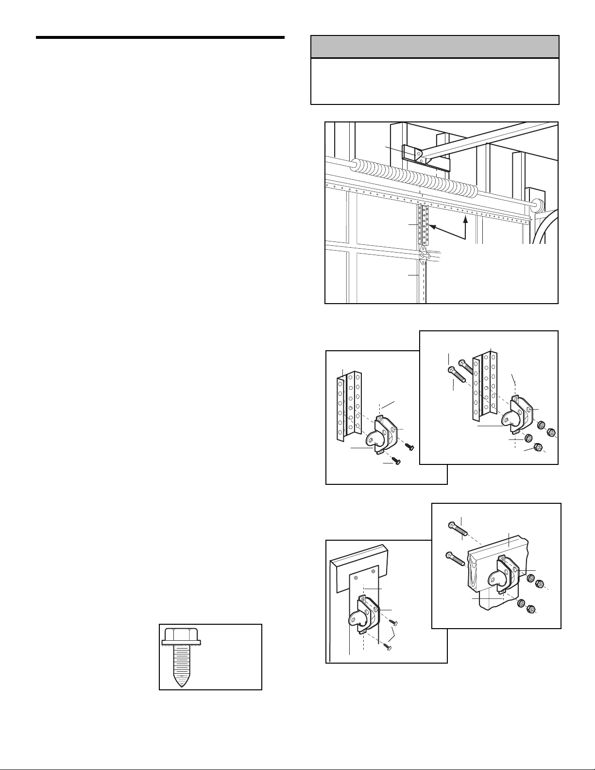
19
Fiberglass, aluminum or lightweight steel garage doors WILL
REQUIRE reinforcement BEFORE installation of door bracket.
Contact your door manufacturer for reinforcement kit.
INSTALLATION STEP 12
Fasten the Door Bracket
Follow instructions which apply to your door type as
illustrated below or on the following page.
A horizontal reinforcement brace should be long
enough to be secured to two or three vertical
supports. A vertical reinforcement brace should
cover the height of the top panel.
Figure 1 shows one piece of angle iron as the horizontal
brace. For the vertical brace, 2 pieces of angle iron are
used to create a U-shaped support. The best solution is
to check with your garage door manufacturer for an
opener installation door reinforcement kit.
NOTE: Many door reinforcement kits provide for direct
attachment of the clevis pin and door arm. In this case
you will not need the door bracket; proceed to Step 13.
SECTIONAL DOORS
1. Center the door bracket on the previously marked
vertical centerline used for the header bracket
installation. Note correct UP placement, as stamped
inside the bracket.
2. Position the top edge of the bracket 2"-4"
(5-10 cm) below the top edge of the door, OR directly
below any structural support across the top of the door.
3. Mark, drill holes and install as follows, depending on
your door’s construction:
Metal or light weight doors using a vertical angle iron
brace between the door panel support and the door
bracket:
• Drill 3/16" fastening holes. Secure the door bracket
using the two 1/4"-14x5/8" self-threading screws
(Figure 2A).
• Alternately, use two 5/16" bolts, lock washers and nuts
(not provided) (Figure 2B).
Metal, insulated or light weight factory reinforced
doors:
• Drill 3/16" fastening holes. Secure the door bracket
using the self-threading screws (Figure 3).
Wood Doors:
• Use top and bottom or side to side door bracket holes.
Drill 5/16" holes through the door and secure bracket
with 5/16"x2" carriage bolts, lock washers and nuts
(not provided) (Figure 4).
NOTE: The 1/4"-14x5/8" self-threading screws are not
intended for use on wood doors.
Figure 1
Figure 2A
Figure 3
Figure 4
Figure 2B
HARDWARE
SHOWN
ACTUAL SIZE
Self-Threading
Screw
1/4"-14x5/8"
CAUTION
Header
Bracket
Door
Bracket
Location
HORIZONTAL AND VERTICAL
REINFORCEMENT IS NEEDED
FOR LIGHTWEIGHT GARAGE
DOORS (FIBERGLASS,
ALUMINUM, STEEL, DOORS
WITH GLASS PANEL, ETC.).
(NOT PROVIDED)
Vertical
Door
Bracket
Lock Washer
5/16"
Bolt
5/16"x2"
Vertical
Centerline
of Garage
Door
Reinforcement
Inside Edge
of Door or
Reinforcement Board
(Not Provided)
Bolt
5/16"-18x2"
(Not Provided)
Vertical
Centerline
of Garage Door
Nut
5/16"-18
UP
UP
Vertical
Reinforcement
Door
Bracket
Self-Threading
Screw
1/4"-14x5/8"
Vertical
Centerline
of Garage
Door
Vertical
Centerline
of Garage Door
Vertical
Centerline
of Garage Door
UP
Self-Threading
Screw
1/4"-14x5/8"
UP
Page 20
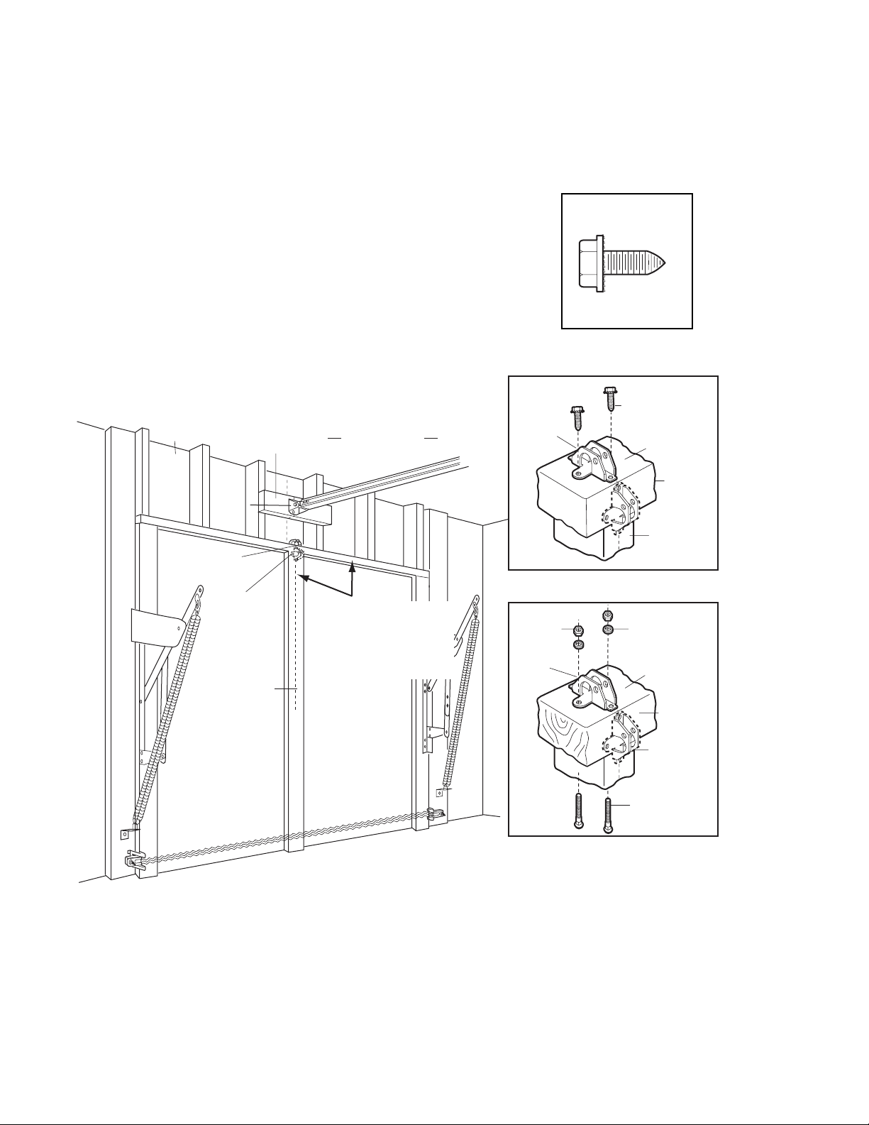
20
ONE-PIECE DOORS
Please read and comply with the warnings and
reinforcement instructions on the previous page. They
apply to one-piece doors also.
• Center the door bracket on the top of the door, in line
with the header bracket as shown. Mark either the left
and right, or the top and bottom holes.
• Metal Doors: Drill 3/16" pilot holes and fasten the
bracket with the 1/4"-14x5/8" self-threading screws
provided.
• Wood Doors: Drill 5/16" holes and use 5/16"x2"
carriage bolts, lock washers and nuts (not provided) or
5/16"x1-1/2" lag screws (not provided) depending on
your installation needs.
NOTE: The door bracket may be installed on the top
edge of the door if required for your installation.
(Refer to the dotted line optional placement drawing.)
HARDWARE SHOWN
ACTUAL SIZE
Header Wall
Header
Bracket
Door
Bracket
Optional
Placement
of Door
Bracket
Vertical
Centerline of
Garage Door
2x4 Support
Finished Ceiling
HORIZONTAL AND VERTICAL
REINFORCEMENT IS NEEDED
FOR LIGHTWEIGHT GARAGE
DOORS (FIBERGLASS,
ALUMINUM, STEEL, DOORS
WITH GLASS PANEL, ETC.).
(NOT PROVIDED)
Door
Bracket
Nut
5/16"-18
Door
Bracket
Self-Threading Screw
1/4"-14x5/8"
Self-Threading
Screw
1/4"-14x5/8"
Top of Door
(Inside
Garage)
Top Edge
of Door
Optional
Placement
METAL DOOR
Lock
Washer
5/16"
Top of Door
(Inside
Garage)
Top Edge
of Door
For a door with no exposed framing,
or for the optional installation, use
lag screws 5/16"x1-1/2" (Not Provided)
to fasten door bracket.
Optional
Placement
Carriage Bolt
5/16"x2"
(Not Provided)
WOOD DOOR
Page 21
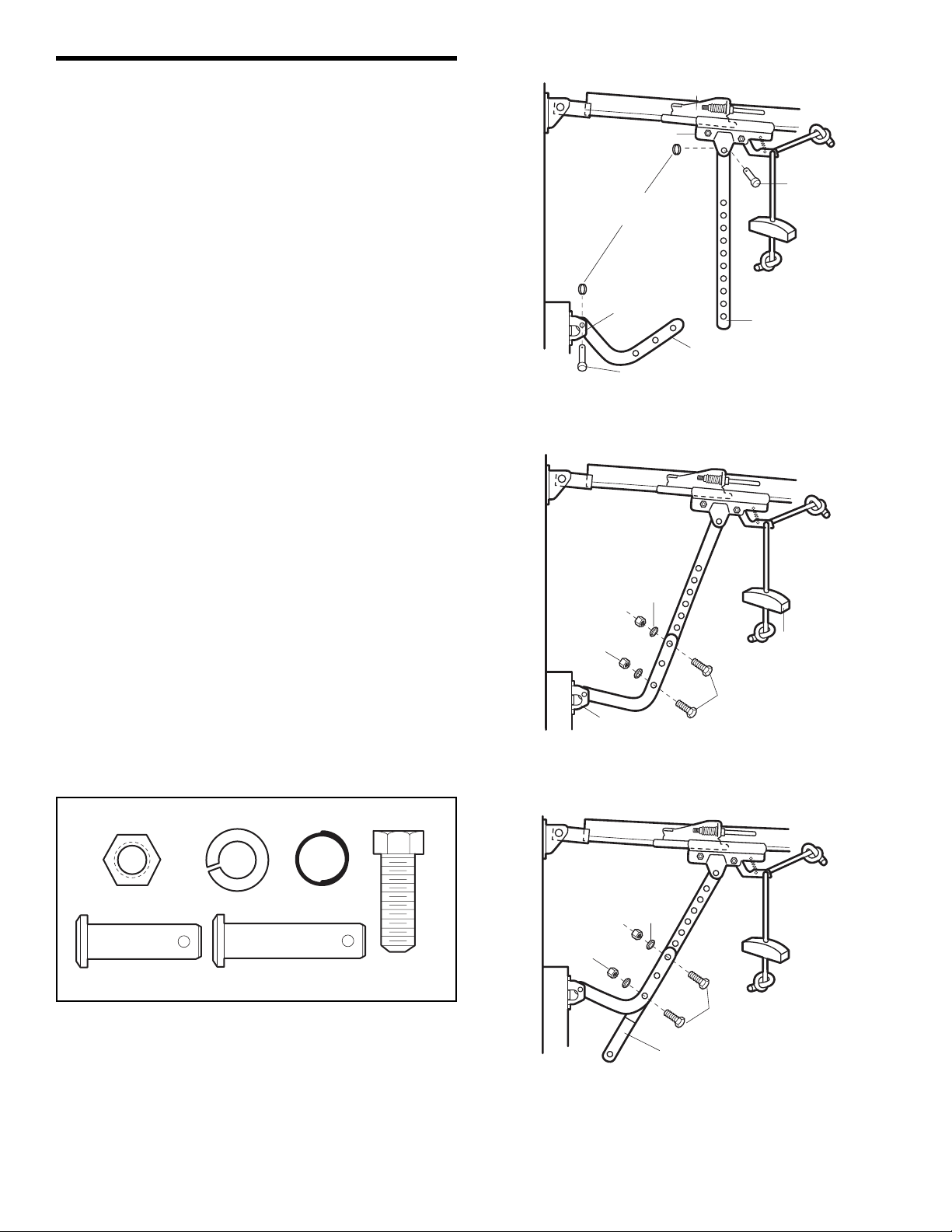
21
INSTALLATION STEP 13
Connect Door Arm to Trolley
Follow instructions which apply to your door type as
illustrated below and on the following page.
SECTIONAL DOORS ONLY
Make sure garage door is fully closed. Pull the
emergency release handle to disconnect the outer trolley
from the inner trolley. Slide the outer trolley back (away
from the door) about 2" (5 cm) (Figures 1, 2 and 3.
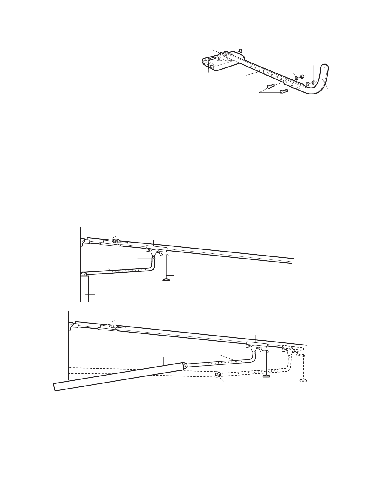
Figure 1:
• Fasten straight door arm section to outer trolley with
the 5/16"x1" clevis pin. Secure the connection with a
ring fastener.
• Fasten curved section to the door bracket in the
same way, using the 5/16"x1-1/4" clevis pin.
Figure 2:
• Bring arm sections together. Find two pairs of holes
that line up and join sections. Select holes as far
apart as possible to increase door arm rigidity.
Figure 3, Hole alignment alternative:
• If holes in curved arm are above holes in straight
arm, disconnect straight arm. Cut about 6"
(15 cm) from the solid end. Reconnect to trolley with
cut end down as shown.
• Bring arm sections together.
• Find two pairs of holes that line up and join with
bolts, lock washers and nuts.
Pull the emergency release handle toward the opener at
a 45° angle so that the trolley release arm is horizontal.
Proceed to Adjustment Step 1, page 23. Trolley will reengage automatically when opener is operated.
Figure 1
Figure 2
Figure 3
HARDWARE SHOWN ACTUAL SIZE
Inner Trolley
Nuts
5/16"-18
Door Bracket
Outer Trolley
Ring
Fastener
Door
Bracket
Clevis Pin
5/16"x1-1/4"
Lock
Washers
5/16"
Clevis Pin
5/16"x1"
Straight
Door Arm
Curved
Door Arm
Emergency
Release
Handle
Bolts
5/16"-18x7/8"
Nut 5/16"-18
Clevis Pin
5/16"x1" (Trolley)
Lock Washer 5/16"
Clevis Pin
5/16"x1-1/4" (Door Bracket)
Ring Fastener
Hex Bolt
5/16"-18x7/8"
Lock
Washers
5/16"
Nuts
5/16"-18
Bolts
5/16"-18x7/8"
Cut This End
Page 22
22
Figure 5
ALL ONE-PIECE DOORS
1. Assemble the Door Arm:
• Fasten the straight and curved door arm sections
together to the longest possible length (with a 2 or 3
hole overlap).
• Make sure the garage door is fully closed. Connect
the straight door arm section to the door bracket with
the 5/16"x1-1/4" clevis pin.
• Secure with a ring fastener.
• Pull the emergency release handle, disconnecting the
outer trolley from the inner trolley by pulling straight
down on the emergency release handle and sliding
the outer trolley back toward the motor unit.
• Connect the curved door arm section to the trolley
using the 5/16"x1-1/4" clevis pin and ring fastener.
NOTE: Adjusting the limits on the following page:
• The trolley will automatically connect. If not, review
the trolley lockout feature on page 27.
• When setting the up limit on the following page, the
door should not have a “backward” slant when fully
open as illustrated below. A slight backward slant will
cause unnecessary bucking and/or jerking operation
as the door is being opened or closed from the fully
open position.
Figure 4
Door
Bracket
Clevis Pin
5/16"x1-1/4"
Straight
Arm
Bolts
5/16"-18x7/8
Ring
Fastener
Lock
Washers
5/16"
Nuts
5/16"-18
Curved
Door Arm
Door Arm
Closed
Door
Inner Trolley
Door Arm
Connector Hole
Inner Trolley
Open Door
Outer Trolley
Correct Angle
Emergency Release Handle
Outer Trolley
Door Arm
Door with
Backward Slant (Incorrect)
Page 23
ADJUSTMENT STEP 1
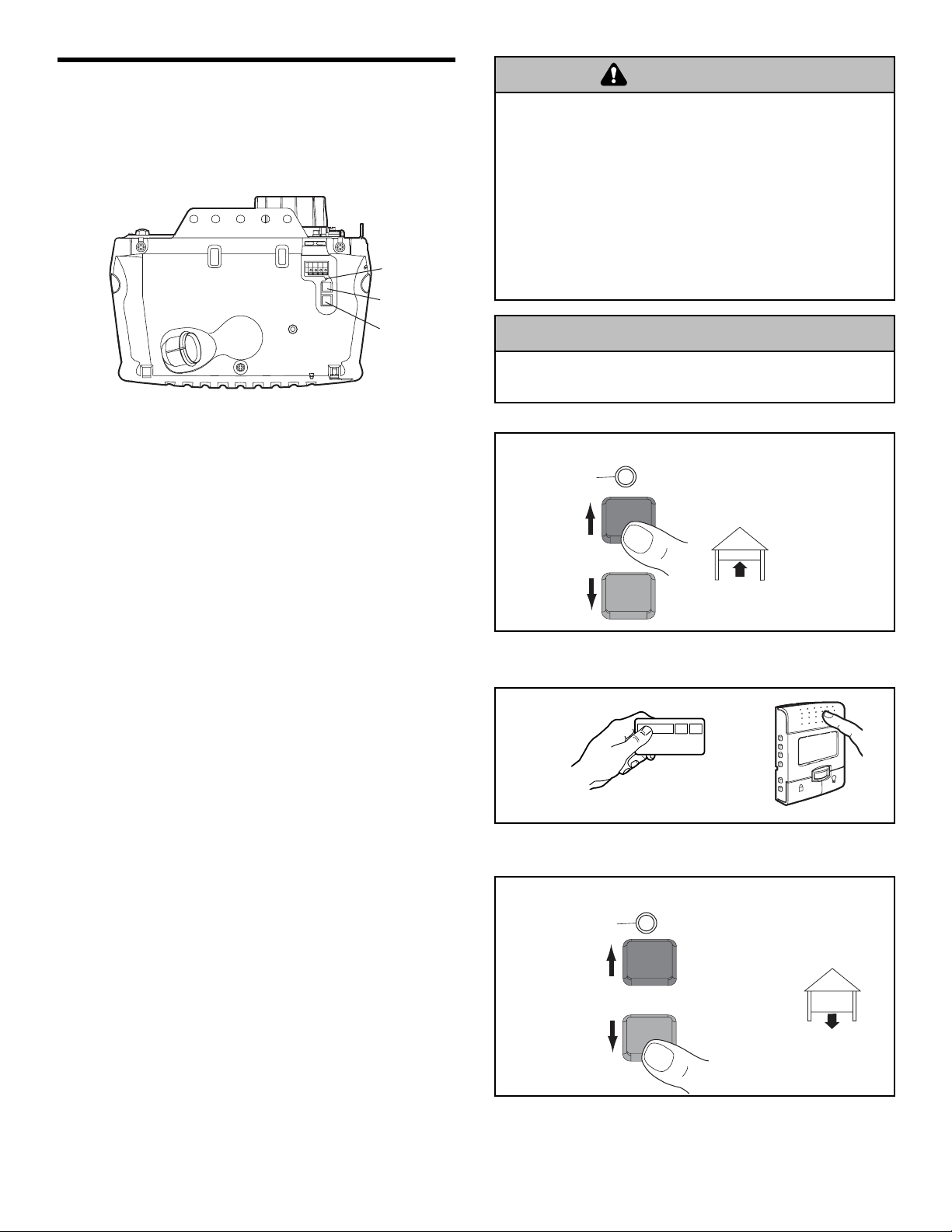
Program the Travel Limits
Travel limits regulate the points at which the door
will stop when moving up or down. Follow the steps
below to set the limits.
To program the travel limits:
Adjust the position of the door by using the black and
purple buttons. Black moves the door UP (open) and
purple moves the door DOWN (close).
1. Setting the UP position: Press and hold the black
button until the yellow indicator light starts flashing
slowly then release.
2. Push and hold the black button until the door reaches
the desired UP (open) position (Figure 2).
NOTE: Check to be sure the door opens high enough for
your vehicle.
3. Push the remote control or door control (Figure 3).
This sets the UP (open) limit and begins closing the
door.
4. Immediately when the door begins to move down,
press and release either the black or purple button.
This will stop the door.
5. Setting the DOWN position: Push and hold the
purple button until the door reaches the desired
DOWN (closed) position (Figure 4).
6. Once the door is closed, if there appears to have too
much pressure on the door, you may toggle the door
back and forth using the black and purple buttons to
reach the desired closed position.
7. Push the remote control or the door control (Figure 3).
This sets the DOWN (close) limit and should bring the
door to the open position.
• If the opener is not stopping exactly where you
would like it, repeat steps 1 through 7 and program
the limits again.
• When the unit stops in both the desired up (open)
and down (close) positions, proceed to
Adjustment Steps 2, Setting the Force.
23
Without a properly installed safety reversal system, persons
(particularly small children) could be SERIOUSLY INJURED
or KILLED by a closing garage door.
• Incorrect adjustment of garage door travel limits will
interfere with proper operation of safety reversal system.
• NEVER use force adjustments to compensate for a binding
or sticking garage door.
• After ANY adjustments are made, the safety reversal system
MUST be tested. Door MUST reverse on contact with 1-1/2"
(3.8 cm) high object (or 2x4 laid flat) on floor.
To prevent damage to vehicles, be sure fully open door
provides adequate clearance.
Figure 2
Figure 4
or
Figure 3
Figure 1
L
O
C
K
L
I
G
H
T
Indicator
Light
Black Button
WARNING
Purple Button
CAUTION
Indicator Light
BLACK
Push and hold
until the door
is at desired UP
position
PURPLE
Indicator Light
BLACK
Push either
button to stop
door at desired
DOWN position
PURPLE
Page 24
24
ADJUSTMENT STEP 2
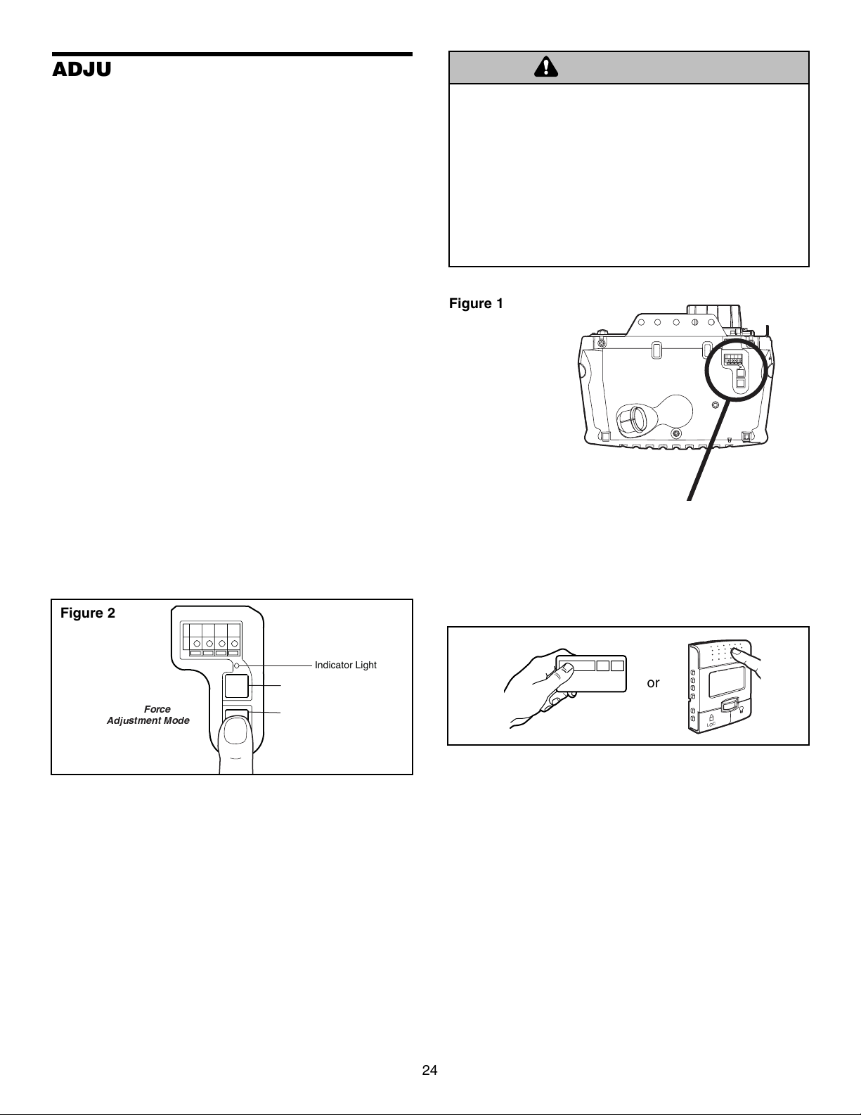
Setting the Force
The force setting button is located on the left panel
of the motor unit. The force setting measures the
amount of force required to open and close the door.
1. Locate the purple button on the left panel of the motor
unit (Figure 1).
2. Push the purple button twice to enter the opener into
Force Adjustment Mode (Figure 2). The LED (Indicator
Light) will flash quickly.
3. Push the remote control or control console (Figure 3).
The door will travel to the DOWN (close) position.
Push the remote control or control console again, the
door will travel to the UP (open) position. Push the
remote control or control console a third time to send
the door to the DOWN (close) position.
The LED (Indicator Light) will stop flashing when the
force has been learned.
The opener has learned the forces required to open and
close your door.
The door must travel through a complete cycle, UP and
DOWN, in order for the force to be set properly. If the
opener cannot open and close your door fully, inspect
your door to insure that it is balanced properly and is not
sticking or binding. See page 3, “Preparing your
garage door.”
Without a properly installed safety reversal system, persons
(particularly small children) could be SERIOUSLY INJURED
or KILLED by a closing garage door.
• Too much force on garage door will interfere with proper
operation of safety reversal system.
• NEVER use force adjustments to compensate for a binding
or sticking garage door.
• After ANY adjustments are made, the safety reversal
system MUST be tested. Door MUST reverse on contact
with 1-1/2" (3.8 cm) high object (or 2x4 laid flat) on floor.
Figure 2
Figure 1
or
Figure 3
WARNING
Push Purple button
twice to enter
unit into
Force
Adjustment Mode
Indicator Light
Black Button
Purple Button
T
H
G
I
L
K
C
O
L
Page 25
25
Without a properly installed safety reversal system, persons
(particularly small children) could be SERIOUSLY INJURED
or KILLED by a closing garage door.
• Safety reversal system MUST be tested every month.
• After ANY adjustments are made, the safety reversal
system MUST be tested. Door MUST reverse on contact
with 1-1/2" high (3.8 cm) object (or 2x4 laid flat) on
the floor.
ADJUSTMENT STEP 3
Test the Safety Reversal System
TEST
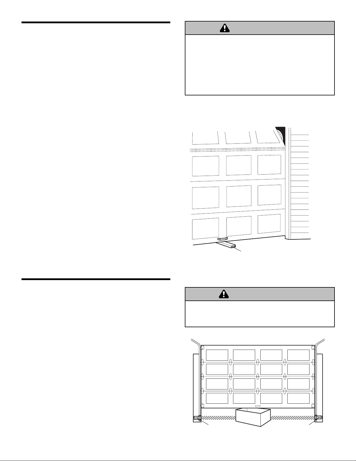
• With the door fully open, place a 1-1/2" (3.8 cm) board
(or a 2x4 laid flat) on the floor, centered under the
garage door.
• Operate the door in the down direction. The door must
reverse on striking the obstruction.
ADJUST
• If the door stops on the obstruction, it is not traveling
far enough in the down direction. Complete Adjustment
Steps 1 and 2 Programming the Limits and Forces.
NOTE: On a sectional door, make sure limit
adjustments do not force the door arm beyond a
straight up and down position. See Figure 3, page 21.
• Repeat the test.
• When the door reverses on the 1-1/2" (3.8 cm) board
(or 2x4 laid flat), remove the obstruction and run the
opener through 3 or 4 complete travel cycles to test
adjustment.
• If the unit continues to fail the Safety Reverse Test, call
for a trained door systems technician.
IMPORTANT SAFETY CHECK:
Test the Safety Reverse System after:
• Each adjustment of door arm length, limits, or force
controls.
• Any repair to or adjustment of the garage door
(including springs and hardware).
• Any repair to or buckling of the garage floor.
• Any repair to or adjustment of the opener.
ADJUSTMENT STEP 4
Test The Protector System
®
(Safety Sensors)
• Press the remote control push button to open the door.
• Place the opener carton in the path of the door.
• Press the remote control push button to close the door.
The door will not move more than an inch (2.5 cm),
and the opener lights will flash.
The garage door opener will not close from a remote if
the indicator light in either sensor is off (alerting you to
the fact that the sensor is misaligned or obstructed).
If the opener closes the door when the safety
reversing sensor is obstructed (and the sensors are
no more than 6" (15 cm) above the floor), call for a
trained door systems technician.
Without a properly installed safety reversing sensor, persons
(particularly small children) could be SERIOUSLY INJURED
or KILLED by a closing garage door.
WARNING
1-1/2" (3.8 cm) board
(or a 2x4 laid flat)
WARNING
Safety Reversing Sensor
Safety Reversing Sensor
Page 26
26
Using Your Garage Door Opener
Your Security✚®opener and hand-held remote control
have been factory-set to a matching code which changes
with each use, randomly accessing over 100 billion new
codes. Your opener will operate with up to eight
Security✚
®
remote controls and one Security✚®Keyless
Entry System. If you purchase a new remote, or if you
wish to deactivate any remote, follow the instructions in
the Programming section.
Activate your opener with any of the following:
• The hand-held Remote Control: Hold the large push
button down until the door starts to move.
• The wall-mounted control console: Hold the push
button or bar down until the door starts to move.
• The Keyless Entry (See Accessories): If provided with
your garage door opener, it must be programmed
before use. See Programming.
When the opener is activated (with the safety
reversing sensor correctly installed and aligned)
1. If open, the door will close. If closed, it will open.
2. If closing, the door will reverse.
3. If opening, the door will stop.
4. If the door has been stopped in a partially open
position, it will close.
5. If obstructed while closing, the door will reverse. If the
obstruction interrupts the sensor beam, the opener
lights will blink for five seconds.
6. If obstructed while opening, the door will stop.
7. If fully open, the door will not close when the beam is
broken. The sensor has no effect in the opening cycle.
If the sensor is not installed, or is misaligned, the door
won’t close from a hand-held remote. However, you can
close the door with the Control Console, the Outside
Keylock, or Keyless Entry, if you activate them until down
travel is complete. If you release them too soon, the door
will reverse.
The opener lights will turn on under the following
conditions: when the opener is initially plugged in; when
power is restored after interruption; when the opener is
activated.
They will turn off automatically after 4-1/2 minutes or
provide constant light when the Light feature on the
Motion Detecting Control Console is activated. Bulb size
is A19. Bulb power is 100 watts maximum.
Security
✚
®
light feature: Lights will also turn on when
someone walks through the open garage door. With a
Motion Detecting Door Control Console, this feature may
be turned off as follows: With the opener lights off, press
and hold the light button for 10 seconds, until the light
goes on, then off again. To restore this feature, start with
the opener lights on, then press and hold the light button
for 10 seconds until the light goes off, then on again.
OPERATION
IMPORTANT SAFETY INSTRUCTIONS
To reduce the risk of SEVERE INJURY or DEATH:
1. READ AND FOLLOW ALL WARNINGS AND INSTRUCTIONS.
2. ALWAYS keep remote controls out of reach of children.
NEVER permit children to operate or play with garage control
console push buttons or remote controls.
3. ONLY activate garage door when it can be seen clearly, it is
properly adjusted, and there are no obstructions to door
travel.
4. ALWAYS keep garage door in sight until completely closed.
NO ONE SHOULD CROSS THE PATH OF THE MOVING DOOR.
5. NO ONE SHOULD GO UNDER A STOPPED, PARTIALLY OPEN
DOOR.
6. If possible, use emergency release handle to disengage
trolley ONLY when garage door is CLOSED. Weak or broken
springs or unbalanced door could result in an open door
falling rapidly and/or unexpectedly.
7. NEVER use emergency release handle unless garage
doorway is clear of persons and obstructions.
8. NEVER use handle to pull garage door open or closed. If
rope knot becomes untied, you could fall.
9. If one control (force or travel limits) is adjusted, the other
control may also need adjustment.
10. After ANY adjustments are made, the safety reversal
system MUST be tested.
11. Safety reversal system MUST be tested every month.
Garage door MUST reverse on contact with 1-1/2" high
(3.8 cm) high object (or a 2x4 laid flat) on the floor.
12. ALWAYS KEEP GARAGE DOOR PROPERLY BALANCED
(see page 3). An improperly balanced door may not
reverse when required and could result in SEVERE INJURY
or DEATH.
13. ALL repairs to cables, spring assemblies and other
hardware, ALL of which are under EXTREME tension,
MUST be made by a trained door systems technician.
14. To avoid SERIOUS PERSONAL INJURY or DEATH from
electrocution, disconnect ALL electric and battery power
BEFORE performing ANY service or maintenance.
15.
SAVE THESE INSTRUCTIONS.
WARNING
Page 27
27
Using the Wall-Mounted
Control Console
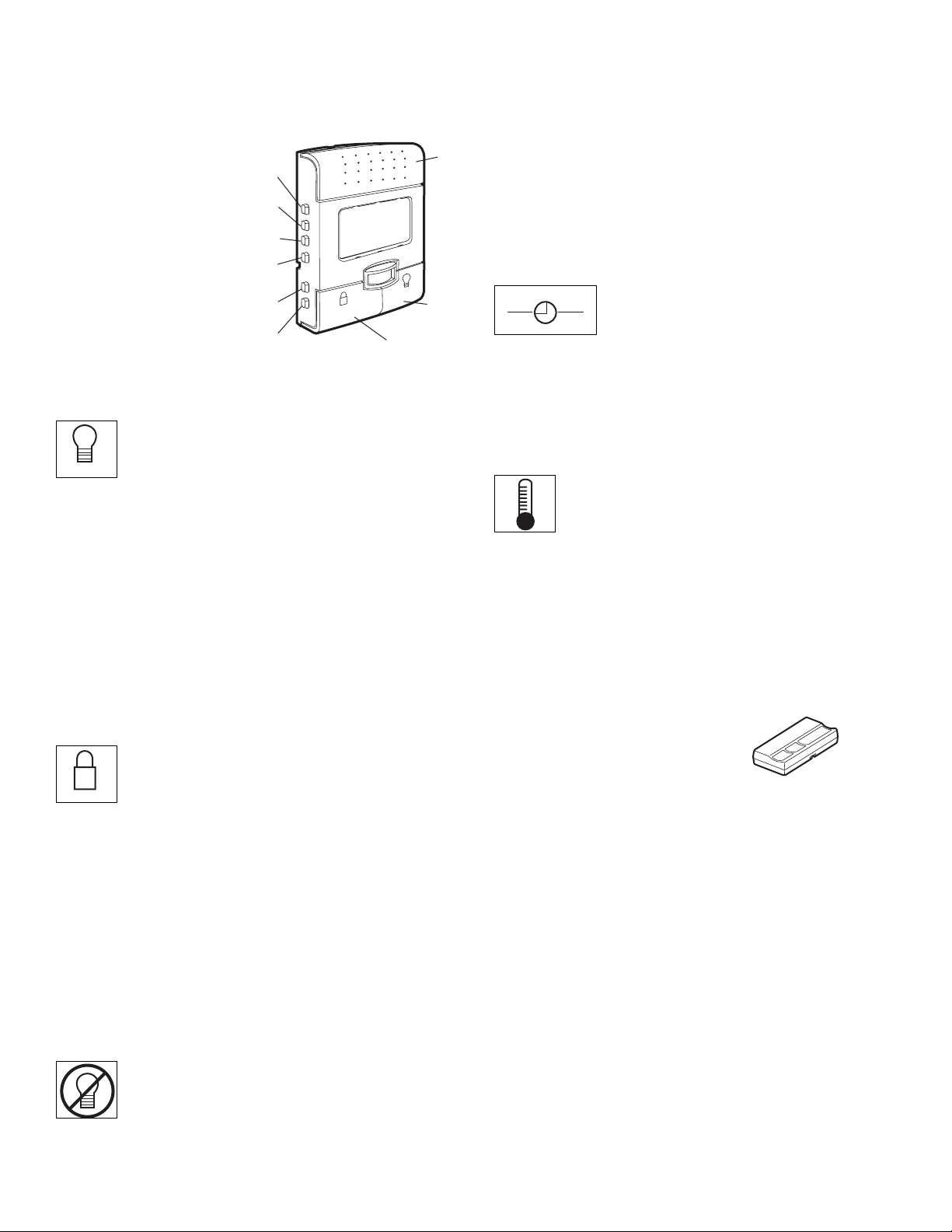
THE LCD MOTION DETECTING CONTROL CONSOLE
Press the push bar to
open or close the
door. Press again to
reverse the door
during the closing
cycle or to stop the
door while it's
opening.
This door control
contains a motion
sensing detector that
will automatically turn
on the light when it
detects a person entering the garage.
Light feature
Press the Light button to turn the opener light on
or off. It will not control the opener lights when
the door is in motion. If you turn it on and then activate
the opener, the light will remain on for 4-1/2 minutes.
Press again to turn it off sooner. The 4-1/2 minute interval
can be changed to 1-1/2, 2-1/2, or 3-1/2 minutes as
follows: Press and hold the Lock button until the light
blinks (about 10 seconds). A single blink indicates that
the timer is reset to 1-1/2 minutes. Repeat the procedure
and the light will blink twice, resetting the timer to 2-1/2
minutes. Repeat again for a 3-1/2 minute interval, etc., up
to a maximum of four blinks and 4-1/2 minutes.
When using the opener lights as working lights, we
recommend that you first disable the motion sensor. See
Automatic Light Feature, below.
Lock feature
Designed to prevent operation of the door from
hand-held remote controls. However, the door
will open and close from the Door Control, the Outdoor
Key Switch and the Keyless Entry Accessories.
To activate, press and hold the Lock button for 2
seconds.
To turn off, press and hold the Lock button again for
2 seconds. The Lock feature will also turn off whenever
the “learn” button on the motor unit panel is activated.
Motion Sensing (Automatic Light Feature): The opener
light will turn on automatically when a person enters the
garage. When a person walks in front of the door control,
the light will come on for five minutes, then shut off. This
feature works by detecting body heat.
To disable this feature, push the motion sensing
button on the side of the door control.
We recommend that you disable the motion
sensor when using the opener lights as working lights.
Otherwise, they will turn off automatically if you are
working beyond the sensors range.
(PROG) Learn Feature
The control console is equipped with a PROG <LEARN>
button to assist in learning remote controls to the unit.
Press the PROG <LEARN> button once to initiate
LEARN mode and the display will show ‘Learn Remote
Control - Press Learn Button Again to Confirm’. Press the
PROG <LEARN> button a second time and the display
will show ‘Learn Mode - Press Remote Control Button to
Learn Remote.’ Press the button of the remote control to
be learned and the worklight will blink to confirm the
remote control has been learned.
Hour & Minute Feature
Press or hold either of these side buttons
to increment the hour or minute displayed
on the LCD display.
(LANG) Language Feature
Press this side button to toggle between the three
languages - English, French and Spanish.
Degrees F/C Feature
Press this side button to toggle the temperature
units between Fahrenheit and Celsius.
Display Contrast Adjustment
Press and hold the light button then push the hour button
to increase the contrast or the minute button to decrease
the contrast.
Additional feature when used with the 3-Button
hand-held remote
To control the opener lights:
In addition to operating the door,
you may program the remote to
operate the lights.
1. With the door closed, press and hold a small remote
button that you want to control the light.
2. Press and hold the Light button on the door control.
3. While holding the Light button, press and hold the Lock
button on the door control.
4. After the opener lights flash, release all buttons.
Motion Sensing
On/Off
Prog <Learn>
Hour
Minute
Language
Degrees (F/C)
LIGHT
LOCK
Lock Button
LIGHT
LOCK
Push
Bar
Light
Button
H M
Page 28
28
To Open the Door Manually
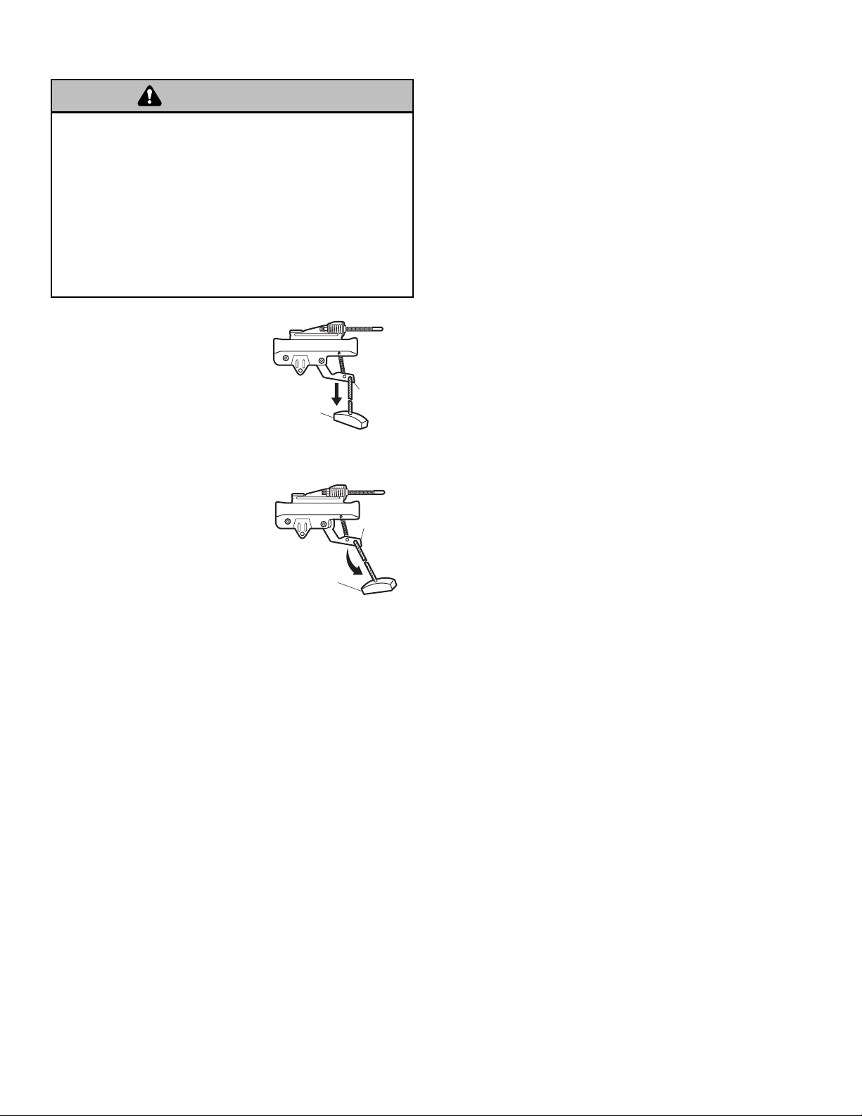
The door should be fully closed if
possible. Pull down on the
emergency release handle and
lift the door manually. To
reconnect the door to the
opener, press the control
console push bar.
The lockout feature prevents the
trolley from reconnecting
automatically. Pull the
emergency release handle down
and back (toward the opener).
The door can then be raised and
lowered manually as often as
necessary. To disengage the
lockout feature, pull the handle
straight down. The trolley will
reconnect on the next UP or
DOWN operation, either
manually or by using the control
console or remote.
To prevent possible SERIOUS INJURY or DEATH from a
falling garage door:
• If possible, use emergency release handle to disengage
trolley ONLY when garage door is CLOSED. Weak or broken
springs or unbalanced door could result in an open door
falling rapidly and/or unexpectedly.
• NEVER use emergency release handle unless garage
doorway is clear of persons and obstructions.
• NEVER use handle to pull door open or closed. If rope knot
becomes untied, you could fall.
LOCKOUT POSITION
MANUAL DISCONNECT
POSITION
WARNING
Emergency
Release
Handle
(Pull Down)
Emergency
Release
Handle
(Down and Back)
N
O
T
IC
E
Trolley
Release
Arm
Trolley
Release
Arm
O
N
E
IC
T
Page 29
29
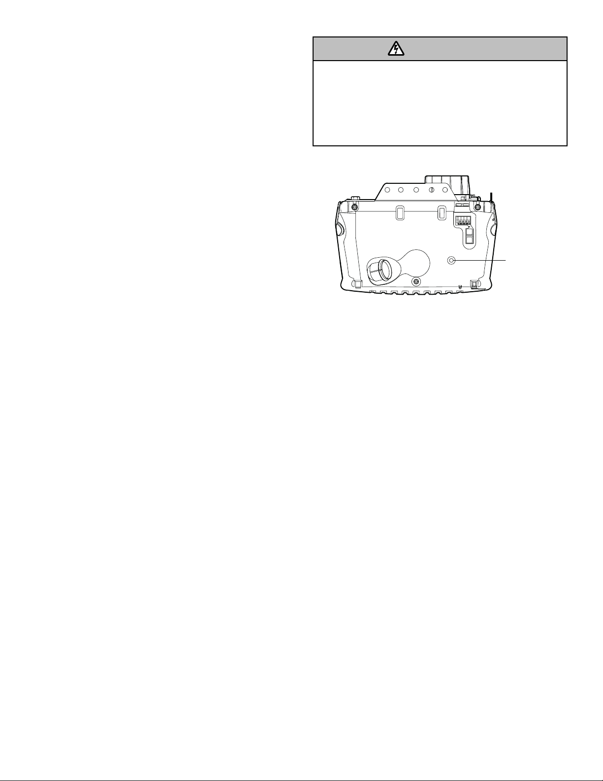
NOTE: LED is most visible with worklight off.
GREEN LED:
All systems are normal.
• A solid LED light indicates the battery is fully charged.
• A flashing LED indicates the battery is being charged.
NOTE: Battery do not have to be fully charged to
operate the motor unit.
ORANGE LED:
The motor unit has lost power and is operating off of the
battery.
• A solid LED with beep, sounding approximately every
2 seconds, indicates the motor unit is activating the
door and is operating off of the battery.
• A flashing LED with beep, sounding every 30 seconds,
indicates battery is low.
• Once the power is restored the battery will recharge.
This is indicated by a flashing green LED.
RED LED:
• If a red LED remains on when the power is restored,
and is accompanied by a beep sounding every 30
seconds, please call for service.
• To obtain maximum battery life and prevent damage,
also disconnect the battery if you unplug the motor
unit while on vacation or any other extended period
of time.
To reduce the risk of FIRE or INJURY to persons:
• Disconnect ALL electric and battery power BEFORE
performing ANY service or maintenance.
• Use only LiftMaster part # 485LM for replacement battery.
• Do NOT dispose of battery in fire. Battery may explode.
Check with local codes for disposal instructions.
Battery Backup (Optional)
OPERATING INSTRUCTIONS
1. Test the installed battery with the motor unit.
To test the battery, disconnect the motor unit power cord
from the electrical outlet.
• A solid orange LED indicates the battery is operating
on battery power.
• A flashing orange LED with beep indicates the unit is
operating on battery power and that the battery charge
is low.
• To test the battery is functioning properly, open and
close the garage door.
• Re-connect the motor unit power cord back into the
electrical outlet.
• Verify that the green LED is flashing on the BBU
(indicates that the battery is now charging).
• Test completed.
2. Charge the battery.
• Battery will take 24 to 48 hours to fully charge.
A fully charged battery supplies 12V DC to the motor unit
for one to two days of normal operation during an
electrical power outage. If the battery voltage drops too
low, the batteries will disconnect and the motor unit will
no longer operate under battery power.
After the electrical power has been restored, the battery
will recharge within 48 hours. Under normal usage
batteries will last 3 to 5 years.
To obtain maximum battery life and prevent damage,
disconnect the battery when motor unit is unplugged
for an extended period of time.
NOTE: Door operation may be limited until battery is fully
charged. The motor unit’s lights will not turn on during
battery mode.
WARNING
Battery Status LED
Page 30
30
Care of Your Opener
MAINTENANCE SCHEDULE
Once a Month
• Manually operate door. If it is unbalanced or binding,
call a trained door systems technician.
• Check to be sure door opens & closes fully. Adjust
limits and/or force if necessary (see pages 23 and 24).
• Repeat the safety reverse test. Make any necessary
adjustments (see Adjustment Step 3).
Once a Year
• Oil door rollers, bearings and hinges. The opener does
not require additional lubrication. Do not grease the
door tracks.
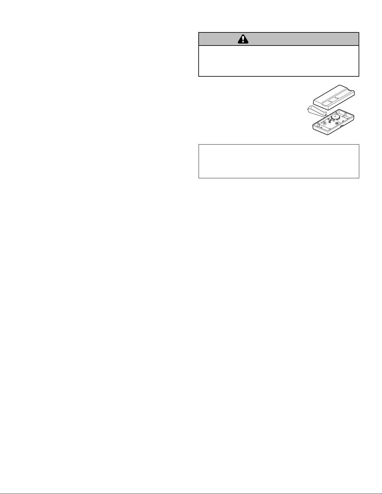
THE REMOTE CONTROL BATTERY
The lithium battery should produce power
for up to 5 years. To replace battery,
use the visor clip or screwdriver blade
to pry open the case as shown. Insert
battery positive side up.
Dispose of old battery properly.
NOTICE: To comply with FCC and or Industry Canada (IC) rules, adjustment or modifications of
this receiver and/or remote control are prohibited, except for changing the code setting or
replacing the battery. THERE ARE NO OTHER USER SERVICEABLE PARTS.
Tested to Comply with FCC Standards FOR HOME OR OFFICE USE. Operation is subject to the
following two conditions: (1) this device may not cause harmful interference, and (2) this device
must accept any interference received, including interference that may cause undesired operation.
To prevent possible SERIOUS INJURY or DEATH:
• NEVER allow small children near batteries.
• If battery is swallowed, immediately notify doctor.
WARNING
Page 31
31
Having a Problem (Troubleshooting)
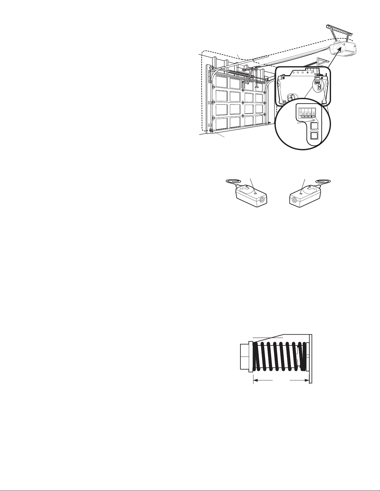
NOTE: Always unplug battery prior to troubleshooting.
1. My door will not close and the light bulbs blink on
my motor unit: The safety reversing sensor must be
connected and aligned correctly before the garage
door opener will move in the down direction.
• Verify the safety reversing sensors are properly
installed, aligned and free of any obstructions. Refer
to Installation Step 10: Install The Protector System
®
.
• Check diagnostic LED for flashes on the motor unit
then refer to the Diagnostic Chart on the
following page.
2. My remotes will not activate the door:
• Verify your Motion Detecting Control Console does
not display “Lock Mode.” If it does, deactivate the
Lock Mode following the instructions for Using the
Motion Detecting Control Console.
• Reprogram remotes following the programming
instructions. Refer to Programming.
• If remote will still not activate your door, check
diagnostic LED for flashes on motor unit then refer to Diagnostic Chart on the following page.
3. My door reverses for no apparent reason: Repeat
safety reverse test after adjustments to force or travel
limits. The need for occasional adjustment for the force
and limit settings is normal. Weather conditions in
particular can affect door travel.
• Manually check door for balance or any binding
problems.
• Refer to Adjustment Step 2, Setting the Force.
4. My door reverses for no apparent reason after fully
closing and touching the floor: Repeat safety
reverse test after adjustments to force or travel limits.
The need for occasional adjustment for the force and
limit settings is normal. Weather conditions in particular
can affect door travel.
• Refer to Adjustment Step 1, Program the Travel
Limits. Decrease down travel.
5. My lights will not turn off when door is open:
• The garage door opener is equipped with a security
light feature. This feature activates the light on when
the safety reversing sensor beam has been
obstructed. Refer to Operation section; Using the
Wall Mounted Control Console, Light Feature.
6. My motor unit hums briefly:
• First verify that the trolley is against the stop bolt.
• Release the door from the opener by pulling the
Emergency Release Rope.
• Manually bring the door to a closed position.
• Loosen the belt by adjusting the outer nut 4 to 5
turns. This relieves the tension.
• Run the motor unit from the remote control or control
console. The trolley should travel towards the door
and stop. If the trolley re-engages with the door, pull
the Emergency Release Rope to disengage.
• Decrease the UP travel by turning the UP Travel
adjustment screw 2 full turns away from the arrow.
• Re-Tighten the outer nut until the trolley spring is
approximately 1-1/4" (3.18 cm) in length.
• If the trolley does not move away from the bolt,
repeat the steps above.
7. If battery status LED is not lit properly:
• Check battery connections.
Bell Wire
Diagnostics
Located On
Safety Reversing Sensor
Sending Eye Safety
Reversing Sensor
(Amber Indicator Light)
Motor Unit
“Learn”
Button
LED or
Diagnostic
LED
Receiving Eye
Safety Reversing Sensor
(Green Indicator Light)
Trolley
1-1/4"
(3.18 cm)
Page 32
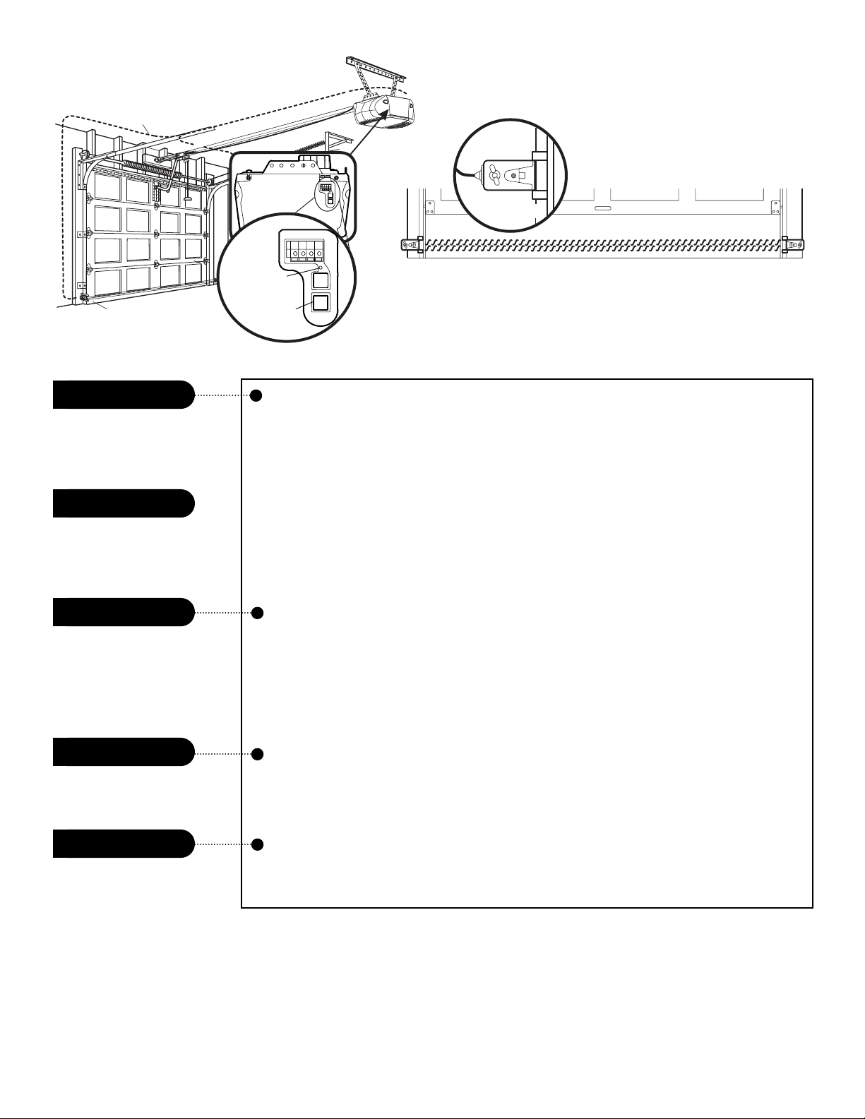
32
Bell Wire
Your garage door opener is programmed with self-diagnostic
capabilities. The “Learn” button/diagnostic LED will flash a
number of times then pause signifying it has found a potential
issue. Consult Diagnostic Chart below.
Diagnostic Chart
Symptom: One or both of the Indicator lights on the safety reversing sensors
do not glow steady.
• Inspect sensor wires for a short (staple in wire), correct wiring polarity (black/white
wires reversed), broken or disconnected wires, replace/attach as needed.
• Disconnect all wires from back of motor unit.
• Remove sensors from brackets and shorten sensor wires to 1-2 ft (30-60 cm) from
back each of sensor.
• Reattach sending eye to motor unit using shortened wires. If sending eye indicator
light glows steadily, attach the receiving eye.
• Align sensors, if the indicator lights glow replace the wires for the sensors. If the
sensor indicator lights do not light, replace the safety reversing sensors.
Symptom: LED is not lit on control console.
• Inspect control console/wires for a short (staple in wire), replace as needed.
• Disconnect wires at control console, touch wires together. If motor unit activates,
replace control console.
• If motor unit does not activate, disconnect control console wires from motor unit.
Momentarily short across red and white terminals with jumper wire. If motor unit
activates, replace control console wires.
Symptom: Sending indicator light glows steadily, receiving indicator light is
dim or flashing.
• Realign receiving eye sensor, clean lens and secure brackets.
• Verify door track is firmly secured to wall and does not move.
Symptom: RPM Sensor = Short travel 6-8" (15-20 cm).
• Unplug unit to reset. Try to operate motor unit, check diagnostic code.
• If it is still flashing 5 times and motor unit moves 6-8" (15-20 cm), replace
RPM sensor.
Possible RPM sensor
failure. Unplug to reset.
Safety reversing sensors
slightly misaligned
(dim or flashing LED).
Control console or
wire shorted.
Safety reversing sensors
wire shorted or
black/white wire reversed.
Safety reversing sensors
wire open (broken or
disconnected).
1 FLASH
2 FLASHES
3 FLASHES
4 FLASHES
5 FLASHES
OR
Safety Reversing Sensor
Diagnostics
Located On
Motor Unit
“Learn”
Button LED
or Diagnostic
LED
“Learn” Button
Installed
Safety Reversing
Sensor
Page 33
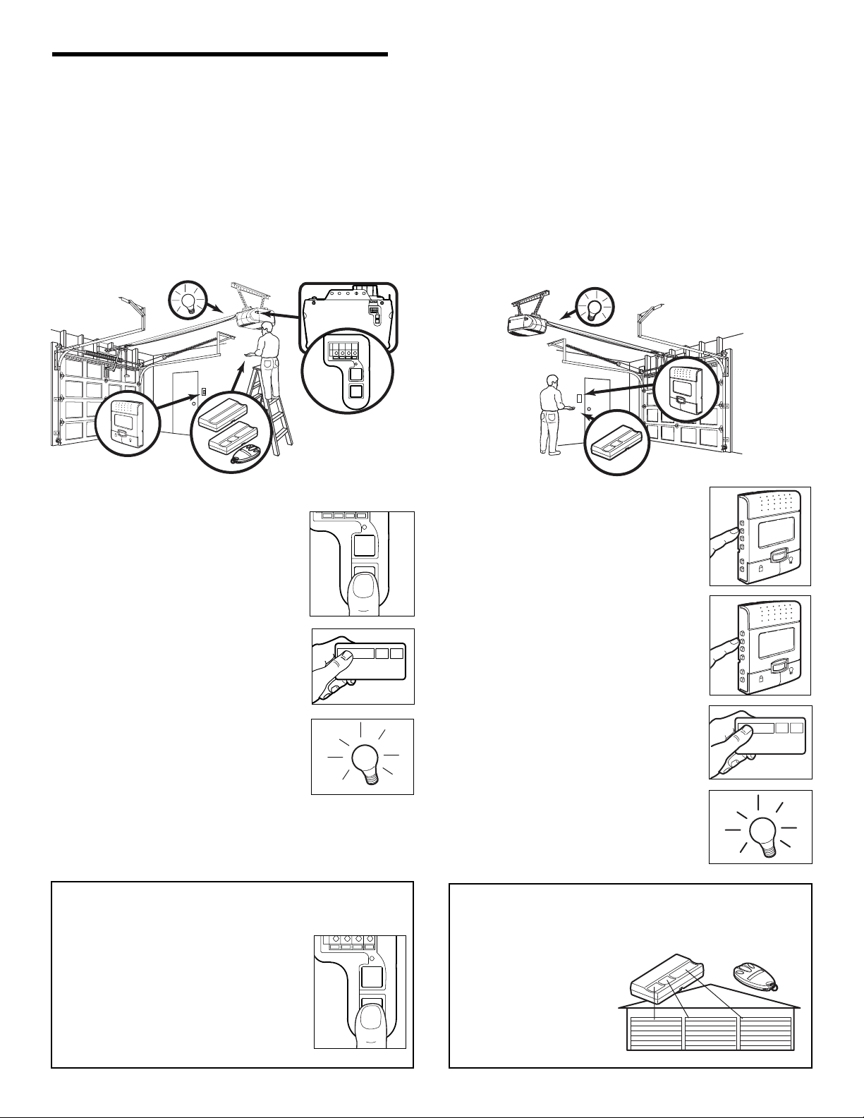
33
*3-Button Remotes
If provided with your garage door opener, the large button
is factory programmed to operate it. Additional buttons on
any Security✚
®
3-button
remote or mini-remote can
be programmed to operate
other Security✚
®
garage
door openers.
To Erase All Codes From Motor
Unit Memory
To deactivate any unwanted remote, first
erase all codes:
Press and hold the “learn” button on motor
unit until the learn indicator light goes out
(approximately 6 seconds). All previous
codes are now erased. Reprogram each
remote or keyless entry you wish to use.
1. Press and release the “learn” button
on the motor unit. The learn indicator
light will glow steadily for 30 seconds.
2. Within 30 seconds, press and hold the
button on the hand-held remote
* that
you wish to operate your garage door.
3. Release the button when the motor
unit lights blink. It has learned the
code. If light bulbs are not installed,
two clicks will be heard.
PROGRAMMING
NOTICE: If this Security
✚
®
garage door opener is operated with a non-rolling code remote control, the technical measure
in the receiver of the garage door opener, which provides security against code-theft devices, will be circumvented. The
owner of the copyright in the garage door opener does not authorize the purchaser or supplier of the non-rolling code
remote control to circumvent that technical measure.
Your garage door opener has already been programmed at the factory to operate with your hand-held remote control.
The door will open and close when you press the large push button.
Below are instructions for programming your opener to operate with additional Security✚
®
remote controls.
To Add or Reprogram a Hand-held Remote Control
USING THE “LEARN” BUTTON
L
O
C
K
L
I
G
H
T
1. Press the PROG <Learn> button
on the LCD/Motion Detecting
Control Console.
2. Press the PROG <Learn> button
again to confirm Learn Mode.
3. Press the button on the hand-held
remote that you wish to operate
your garage door.
4. When the motor unit lights blink, it
has learned the code. If light
bulbs are not installed, two clicks
will be heard.
TO ADD ADDITIONAL REMOTE CONTROLS
USING THE LCD CONTROL CONSOLE
T
H
G
I
L
K
C
O
L
T
H
G
I
L
K
C
O
L
Page 34
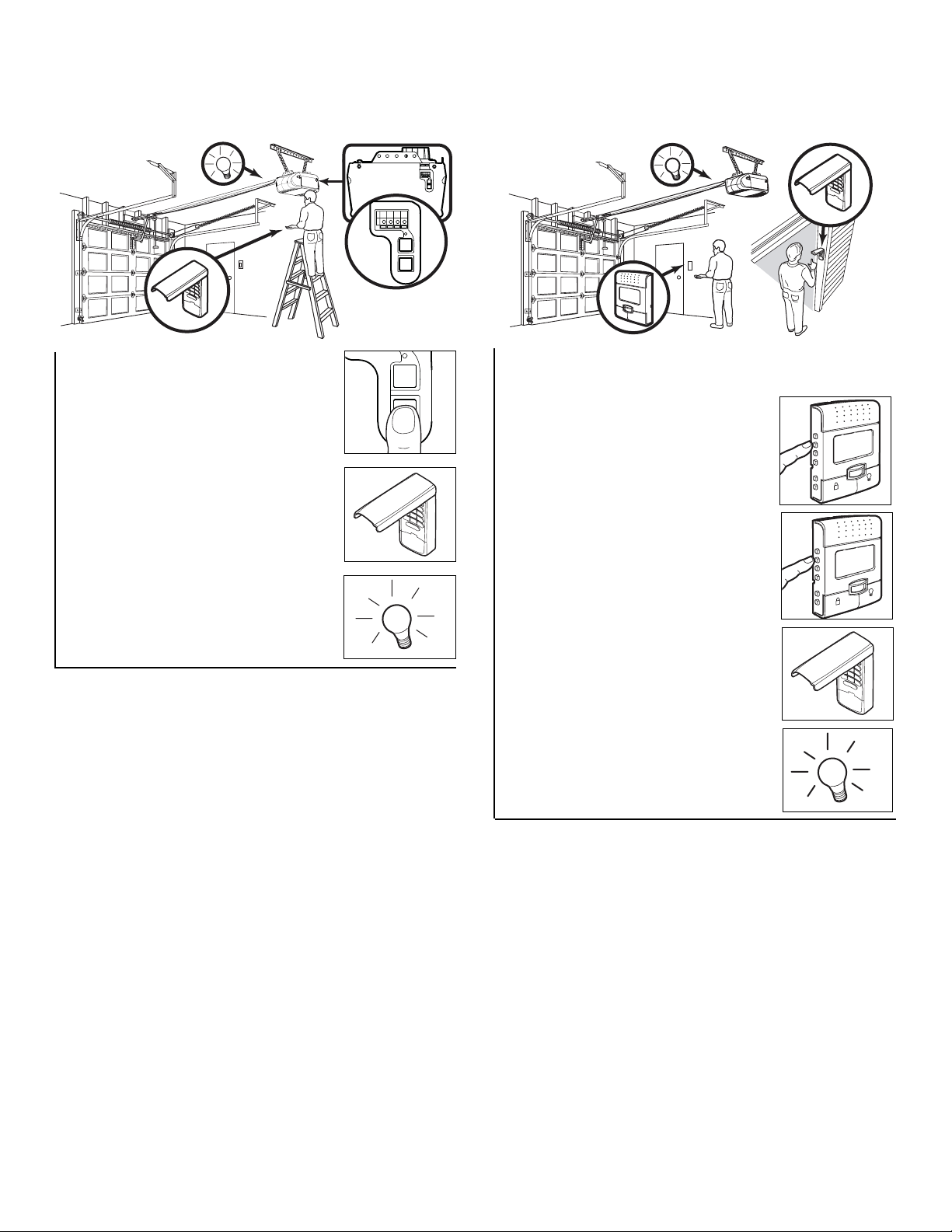
34
1. Press and release the “learn” button
on motor unit. The learn indicator light
will glow steadily for 30 seconds.
2. Within 30 seconds, enter a four digit
personal identification number (PIN) of
your choice on the keypad. Then
press and hold the ENTER button.
3. Release the button when the motor
unit lights blink. It has learned the
code. If light bulbs are not installed,
two clicks will be heard.
To Add, Reprogram or Change a Keyless Entry PIN
NOTE: Your new Keyless Entry must be programmed to operate your garage door opener.
USING THE “LEARN” BUTTON USING THE LCD CONTROL CONSOLE
To change an existing, known PIN
If the existing PIN is known, it may be changed by one
person without using a ladder.
1. Press the four buttons for the present PIN, then press
and hold the # button.
The opener light will blink twice. Release the # button.
2. Press the new 4-digit PIN you have chosen, then
press Enter.
The motor unit lights will blink once when the PIN has been
learned.
Test by pressing the new PIN, then press Enter. The door
should move.
To set a temporary PIN
You may authorize access by visitors or service people with
a temporary 4-digit PIN. After a programmed number of
hours or number of accesses, this temporary PIN expires
and will no longer open the door. It can be used to close the
door even after it has expired. To set a temporary PIN:
1. Press the four buttons for your personal entry PIN (not
the last temporary PIN), then press and hold the ✽
button.
The opener light will blink three times. Release the
button.
2. Press the temporary 4-digit PIN you have chosen, then
press Enter.
The opener light will blink four times.
3. To set the number of hours this temporary PIN will work,
press the number of hours (up to 255), then press ✽.
OR
3. To set the number of times this temporary PIN will work,
press the number of times (up to 255), then press #.
The opener light will blink once when the temporary PIN has
been learned.
Test by pressing the four buttons for the temporary PIN,
then press Enter. The door should move. If the temporary
PIN was set to a certain number of openings, remember
that the test has used up one opening. To clear the
temporary password, repeat steps 1-3, setting the number
of hours or times to 0 in step 3.
1. Press the PROG <Learn> button on
the LCD/Motion Detecting Control
Console.
2. Press the PROG <Learn> button
again to confirm Learn Mode.
3. Enter a four digit personal
identification number (PIN) of your
choice on the keypad. Then press
enter.
4. When the motor unit lights blink, it
has learned the code. If light bulbs
are not installed, two clicks will be
heard.
NOTE: This method requires two people if the Keyless
Entry is already mounted outside the garage.
One Button Close: Opener can be closed by pressing only the ENTER button if the one button close feature has been activated.
This feature has been activated at the factory. To activate or deactivate this feature press and hold buttons 1 and 9 for 10 seconds.
The keypad will blink twice when the one button close is active. The keypad will blink four times when one button close is deactivated.
T
H
G
I
L
K
C
O
L
T
H
G
I
L
K
C
O
L
Page 35
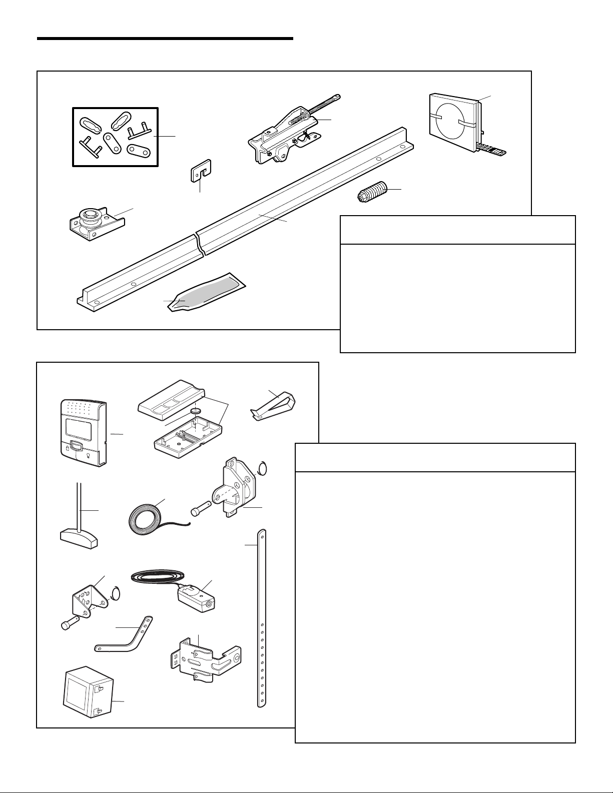
35
KEY PART
NO. NO. DESCRIPTION
1 4A1008 Master link kit
2 41B5424 Belt pulley bracket
3 41B3869-1 Complete trolley assembly
4 109B33 Trolley clip
5 2777BD One-piece rail
6 41A5434-11 Full belt assembly
7 41B4103 Tensioner assembly
8 83A11-2 Rail grease
Installation Parts
REPAIR PARTS
Rail Assembly Parts
KEY PART
NO. NO. DESCRIPTION
1 398LM LCD Motion detecting door control console
2 373LM 3-Button remote control
3 10A20 3V2032 Lithium battery
4 29B137 Remote control visor clip
5 41A2828 Emergency release rope and handle
assembly
6 41B4494-1 2-Conductor bell wire, white & white/red
7 41A5047-1 Door bracket w/ clevis pin & fastener
8 41A4353-1 Header bracket w/clevis pin & fastener
9 41A5034 Safety sensor kit (receiving and sending
eyes) with 3' (.9 m) 2-conductor bell wire
10 178B34 Straight door arm section
11 178B35 Curved door arm section
12 41A5266-1 Safety sensor brackets (2)
13 485LM Battery
NOT SHOWN
101D173 Push bar for door control
41A2770-5 Installation hardware bag (includes
hardware listed on page 5).
114A3281 Owner’s manual
114A3281SP Owner’s manual - Spanish
2
8
6
3
1
7
4
5
1
LO
C
K
LIGH
T
5
N
O
TIC
E
8
Y
L
N
O
T
N
U
O
M
G
N
I
L
I
E
C
P
U
11
13
4
2
3
6
7
10
9
12
Page 36
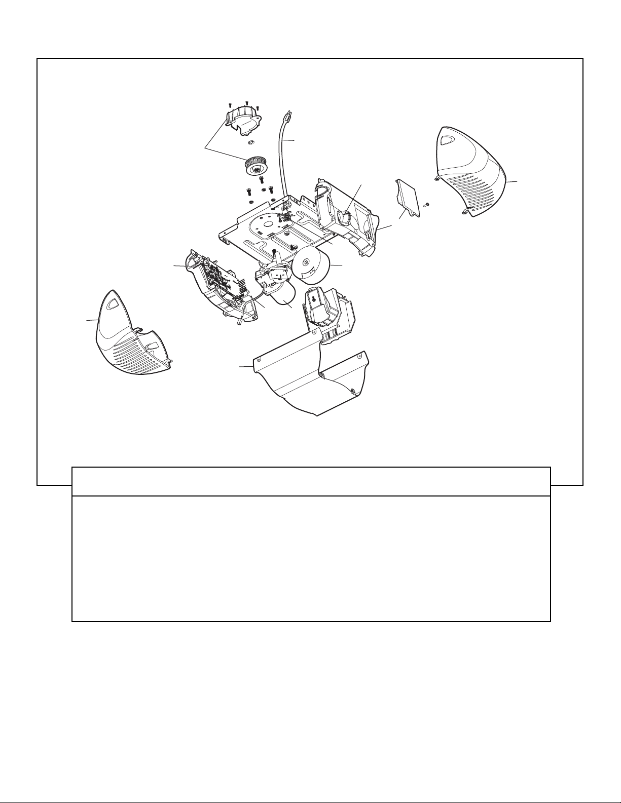
36
KEY PART
NO. NO. DESCRIPTION
1 41C76 Belt cap and sprocket
2 41B4245 Line cord
3 41B4375-3 Terminal block with screws
4 41A6281 Wire harness kit
5 41D794 Motor with positioning sensor
6 41DB002-2 Receiver logic assembly
KEY PART
NO. NO. DESCRIPTION
7 41A6231 End panel with battery door and
screw
8 41C190 Transformer and harness
9 41D504-4 Cover
10 108D79 Light lens
11 175B88 Light socket
NOT SHOWN
485LM Battery kit
Motor Unit Assembly Parts
10
1
2
11
10
7
3
6
4
5
8
9
Page 37
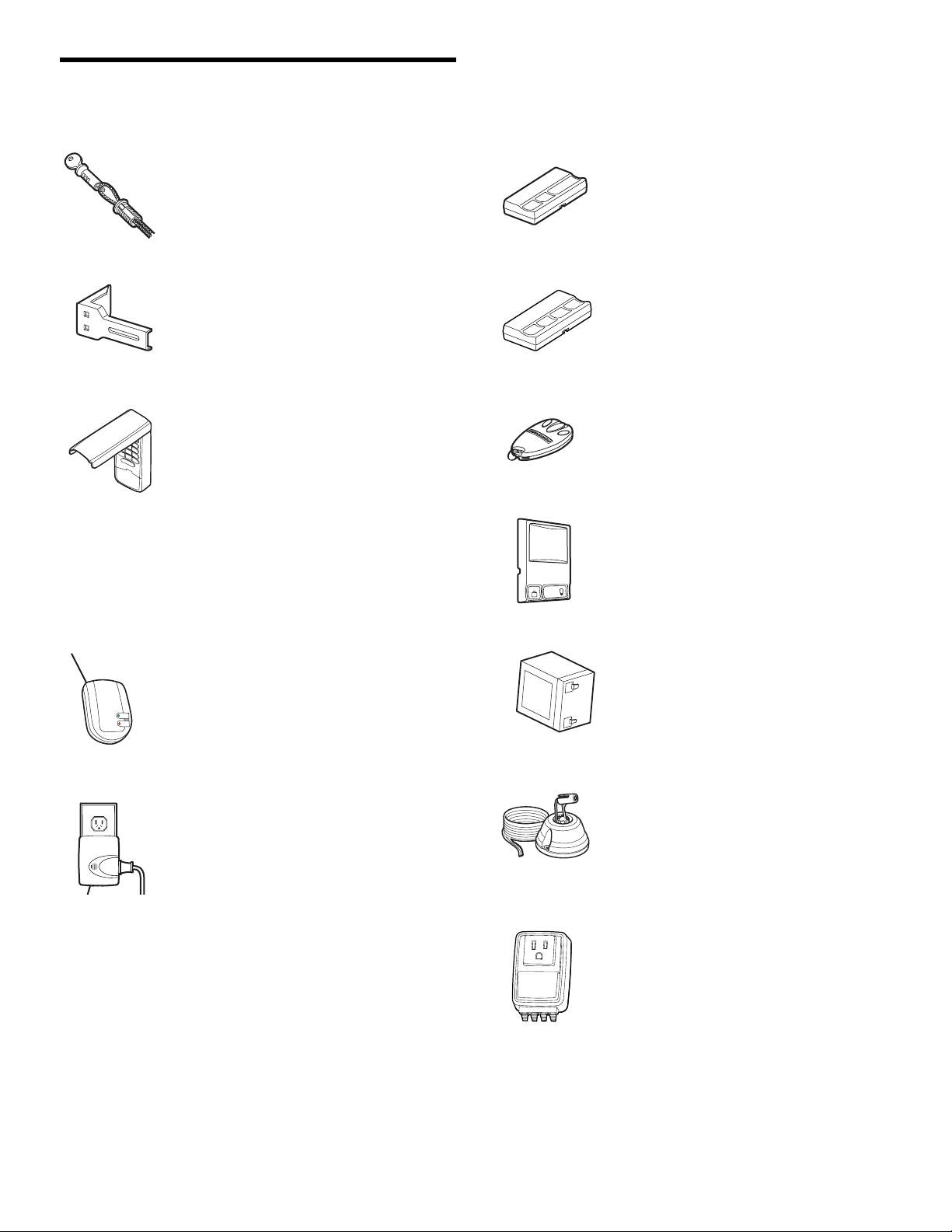
37
ACCESSORIES
374LM
370LM
915LM
395LM
990LM
1702LM
Outside Quick Release:
Required for a garage with NO access
door. Enables homeowner to open
garage door manually from outside by
disengaging trolley.
Remote Light Control:
Enables homeowner to turn on a lamp,
television or other appliance from car,
bedside, or anywhere in the home
with a remote.
SECURITY✚®3-Button Remote
Control:
Wood grain plastic case. Includes visor
clip.
SECURITY✚®4-Button Remote
Control:
Includes visor clip.
Wireless Door Control:
Push bar, light feature and auxiliary
button. Includes battery.
377LM
Extension Brackets:
(Optional) For safety sensor installation
onto the wall or floor.
373W
SECURITY✚®Keyless Entry:
Enables homeowner to operate garage
door opener from outside by entering a
password on a specially designed
keyboard. Also can add a temporary
password for visitors or service
persons. This temporary password can
be limited to a programmable number
of hours or entries. Opener can be
closed by pressing only the ENTER
button if the one button close feature
has been activated.
378LM
SECURITY✚®3-Button Mini Remote
Control:
With key ring and fastening strip.
Battery Backup System:
Provides backup power to the garage
door opener. For use with model
3850 only.
485LM
Surge Protector:
The Garage Door Opener Surge
Protector is designed to protect
LiftMaster
®
garage door openers against
damage from lightning and power
surges.
975LM
Laser Park Assist:
Laser enables homeowners to precisely
park vehicles in the garage.
Garage Door Monitor:
Security for the largest door of your
home!
Tells you if your garage door is open or
closed. Monitors up to 4 garage doors
by adding additional sensor modules.
41A5281
C
L
O
SED
O
P
EN
Page 38

38
NOTES
Page 39

39
Page 40
© 2006, The Chamberlain Group, Inc.
114A3281B All Rights Reserved
HOW TO ORDER
REPAIR PARTS
Selling prices will be furnished on request or parts will be
shipped at prevailing prices and you will be billed
accordingly.
WHEN ORDERING REPAIR PARTS, ALWAYS GIVE THE
FOLLOWING INFORMATION:
• PART NUMBER
• PART NAME
• MODEL NUMBER
ADDRESS ORDERS TO:
THE CHAMBERLAIN GROUP, INC.
Technical Support Group
6020 S. Country Club Road
Tucson, Arizona 85706
SERVICE INFORMATION
TOLL FREE NUMBER:
1-800-528-9131
LIFTMASTER FIVE YEAR LIMITED WARRANTY
LIFETIME MOTOR AND BELT LIMITED WARRANTY
The Chamberlain Group, Inc. (“Seller”) warrants to the first retail purchaser of this product, for the residence in which this product is originally
installed, that it is free from defect in materials and/or workmanship for a period of 60 full months from the date of purchase [and that the motor
and belt] are free from defect in materials and/or workmanship for a period of the lifetime of the product]. The proper operation of this product
is dependent on your compliance with the instructions regarding installation, operation, maintenance and testing. Failure to comply strictly with
those instructions will void this limited warranty in its entirety.
If, during the limited warranty period, this product appears to contain a defect covered by this limited warranty, call 1-800-528-9131, toll free,
before dismantling this product. Then send this product, pre-paid and insured, to our service center for warranty repair. You will be advised of
shipping instructions when you call. Please include a brief description of the problem and a dated proof-of-purchase receipt with any product
returned for warranty repair. Products returned to Seller for warranty repair, which upon receipt by Seller are confirmed to be defective and
covered by this limited warranty, will be repaired or replaced (at Seller’s sole option) at no cost to you and returned pre-paid. Defective parts
will be repaired or replaced with new or factory-rebuilt parts at Seller’s sole option.
ALL IMPLIED WARRANTIES FOR THE PRODUCT, INCLUDING BUT NOT LIMITED TO ANY IMPLIED WARRANTIES OF
MERCHANTABILITY AND FITNESS FOR A PARTICULAR PURPOSE, ARE LIMITED IN DURATION TO THE FIVE YEAR LIMITED
WARRANTY PERIOD SET FORTH ABOVE [EXCEPT THE IMPLIED WARRANTIES WITH RESPECT TO THE MOTOR AND BELT, WHICH
ARE LIMITED IN DURATION TO THE LIFETIME LIMITED WARRANTY PERIOD FOR THE MOTOR AND BELT], AND NO IMPLIED
WARRANTIES WILL EXIST OR APPLY AFTER SUCH PERIOD. Some States do not allow limitations on how long an implied warranty
lasts, so the above limitation may not apply to you. THIS LIMITED WARRANTY DOES NOT COVER NON-DEFECT DAMAGE, DAMAGE
CAUSED BY IMPROPER INSTALLATION, OPERATION OR CARE (INCLUDING, BUT NOT LIMITED TO ABUSE, MISUSE, FAILURE TO
PROVIDE REASONABLE AND NECESSARY MAINTENANCE, UNAUTHORIZED REPAIRS OR ANY ALTERATIONS TO THIS PRODUCT),
LABOR CHARGES FOR REINSTALLING A REPAIRED OR REPLACED UNIT, REPLACEMENT OF BATTERIES AND LIGHT BULBS OR
UNITS INSTALLED FOR NON-RESIDENTIAL USE.
THIS LIMITED WARRANTY DOES NOT COVER ANY PROBLEMS WITH, OR RELATING TO,THE GARAGE DOOR OR GARAGE DOOR
HARDWARE, INCLUDING BUT NOT LIMITED TO THE DOOR SPRINGS, DOOR ROLLERS, DOOR ALIGNMENT OR HINGES.THIS
LIMITED WARRANTY ALSO DOES NOT COVER ANY PROBLEMS CAUSED BY INTERFERENCE. ANY SERVICE CALL THAT
DETERMINES THE PROBLEM HAS BEEN CAUSED BY ANY OF THESE ITEMS COULD RESULT IN A FEE TO YOU.
UNDER NO CIRCUMSTANCES SHALL SELLER BE LIABLE FOR CONSEQUENTIAL, INCIDENTAL OR SPECIAL DAMAGES ARISING IN
CONNECTION WITH USE, OR INABILITY TO USE,THIS PRODUCT. IN NO EVENT SHALL SELLER’S LIABILITY FOR BREACH OF
WARRANTY, BREACH OF CONTRACT, NEGLIGENCE OR STRICT LIABILITY EXCEED THE COST OF THE PRODUCT COVERED
HEREBY. NO PERSON IS AUTHORIZED TO ASSUME FOR US ANY OTHER LIABILITY IN CONNECTION WITH THE SALE OF THIS
PRODUCT.
Some States do not allow the exclusion or limitation of consequential, incidental or special damages, so the above limitation or exclusion may
not apply to you. This limited warranty gives you specific legal rights, and you may also have other rights which vary from state to state.
LIFTMASTER®SERVICE IS
ON CALL
OUR LARGE SERVICE ORGANIZATION
SPANS AMERICA
INSTALLATION AND SERVICE INFORMATION IS AS NEAR
AS YOUR TELEPHONE. SIMPLY DIAL OUR
TOLL FREE NUMBER:
1-800-528-9131
www.liftmaster.com
For professional installation, parts and service, contact
your local LIFTMASTER/CHAMBERLAIN dealer. Look for
him in the Yellow Pages, or call our Service number for a
list of dealers in your area.
 Loading...