

Page 1
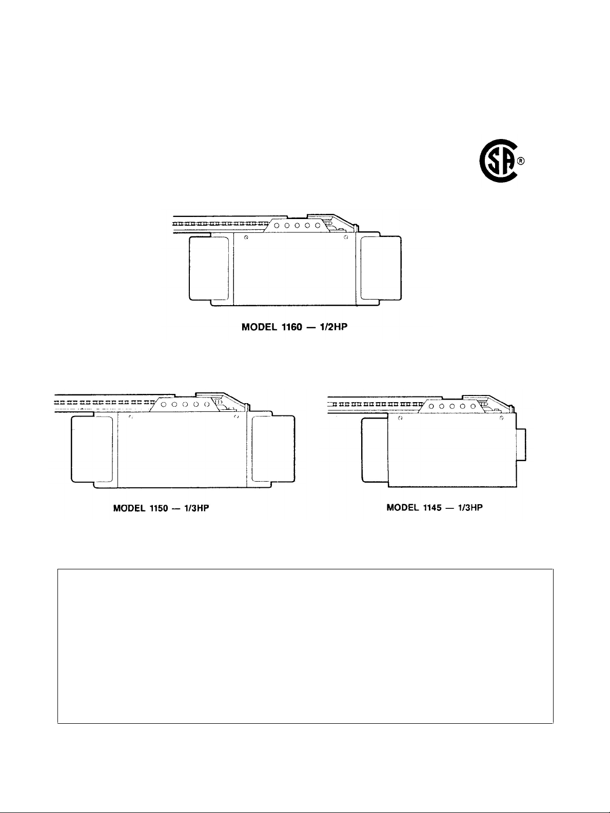
Chamberlain Manufacturing Canada, Inc. Unit 11,
230 Bayview Drive Barrie, Ontario L4N 5E9
Owner's Manual
Garage Door Opener
(1100 Series -- Canada)
FOR RESIDENTIAL USE ONLY
CAUTION! PLEASE READ THIS MANUAL CAREFULLY
The MODEL NUMBER label is located on the front panel of your opener
CONTENTS PAGE
Safety Rules............................................................. 2
Carton Inventory....................................................... 3
Features of Your Opener...........................................3
Specifications........................................................... 3
Accessories.............................................................. 4
Completed Installation Illustration............................. 5
Installation Information............................................. 5
Operation of Your Opener......................................... 6
Care and Maintenance of Your Opener..................... 7
Assembly.................................................................. 8
Installation................................................................ 10
FASTEN THIS MANUAL NEAR THE GARAGE DOOR AFTER INSTALLATION.
PERIODIC CHECKS OF THE OPENER ARE REQUIRED TO INSURE SATISFACTORY OPERATION.
CONTENTS PAGE
Limit Adjustment.......................................................20
Force Adjustment......................................................21
Safety Reverse Test..................................................22
The Protector System.............................................22
Setting/Changing Code.............................................23
Having a Problem? ...................................................24
Repair Parts, Rail Assembly................................ ......26
Repair Parts, Installation...........................................26
Repair Parts, Opener Assembly ................................27
How To Order Repair Parts.......................................28
Warranty...................................................................28
Page 2
CAUTION: IF YOUR GARAGE HAS NO SERVICE ENTRANCE DOOR, INSTALL MODEL 7702 EMERGENCY RELEASE
KEYLOCK. THIS ACCESSORY ALLOWS MANUAL OPERATION OF THE GARAGE DOOR FROM OUTSIDE IN CASE OF
POWER FAILURE.
Install door control button (or any additional
push buttons) IN A LOCATION WHERE GARAGE
DOOR IS VISIBLE, BUT OUT OF THE REACH OF
CHILDREN. DO NOT ALLOW CHILDREN TO
OPERATE PUSH BUTTON(S) OR REMOTE
CONTROL TRANSMITTER. Serious personal
injury from a closing garage door may result
from misuse of the opener.
Use manual release ONLY to disengage the
trolley and, if possible, ONLY when the door Is
closed. DO NOT USE THE RED HANDLE TO
PULL DOOR OPEN OR CLOSED.
DISCONNECT ELECTRIC POWER TO GARAGE
DOOR OPENER BEFORE MAKING REPAIRS OR
REMOVING COVERS.
START BY READING THESE IMPORTANT SAFETY RULES
THIS SAFETY ALERT SYMBOL MEANS
INSTRUCTION.
READ THESE INSTRUCTIONS CAREFULLY.
CAUTION—PERSONAL SAFETY OR PROPERTY DAMAGE
THIS GARAGE DOOR OPENER IS DESIGNED AND TESTED TO OFFER REASONABLY SAFE SERVICE
PROVIDED IT IS INSTALLED AND OPERATED IN STRICT ACCORDANCE WITH THE FOLLOWING
SAFETY INSTRUCTIONS.
FAILURE TO COMPLY WITH THE FOLLOWING INSTRUCTIONS MAY RESULT IN SERIOUS
PERSONAL INJURY OR PROPERTY DAMAGE.
KEEP GARAGE DOOR BALANCED. Sticking or
binding doors must be repaired. Garage doors,
door springs, cables, pulleys, brackets and their
hardware are under extreme tension and can
cause serious personal injury. DO NOT ATTEMPT
TO LOOSEN, MOVE OR ADJUST THEM. Call for
garage door service.
DO NOT WEAR RINGS, WATCHES OR LOOSE
CLOTHING while Installing or servicing a garage
door opener.
To avoid serious personal injury from
entanglement, REMOVE ALL THE ROPES
CONNECTED TO GARAGE DOOR before
installing the garage door opener.
THE SAFETY REVERSE SYSTEM TEST IS VERY
IMPORTANT (page 22). Your garage door
reverse on contact with a 1-inch obstacle placed
on the floor. Failure to properly adjust the
opener may result in serious personal injury
from a closing garage door. REPEAT THE TEST
ONCE A MONTH AND MAKE ANY NEEDED
ADJUSTMENTS.
Fasten the CAUTION LABEL adjacent to the door
control button as a reminder of safe operating
procedures.
MUST
DISENGAGE ALL EXISTING GARAGE DOOR
LOCKS to avoid damage to garage door.
Installation and wiring must be in compliance with
your local building and electrical codes.CONNECT
THE POWER CORD ONLY TO A PROPERLY
GROUNDED OUTLET.
LIGHTWEIGHT DOORS OF FIBERGLASS,
ALUMINUM OR STEEL MUST BE
SUBSTANTIALLY REINFORCED TO AVOID
DOOR DAMAGE. (See page 17.) The best
solution is to check with your garage door
manufacturer for an opener installation
reinforcement kit.
DO NOT USE THE FORCE ADJUSTMENTS TO
COMPENSATE FOR A BINDING OR STICKING
garage door. Excessive force will interfere with
the proper operation of the safety reverse
system or damage the garage door (page 21).
2
CAUTION: Activate opener only when the door is
in full view, free of obstructions and opener is
properly adjusted. NO ONE SHOULD ENTER OR
LEAVE THE GARAGE WHILE DOOR IS IN
MOTION. DO NOT ALLOW CHILDREN TO PLAY
NEAR THE DOOR.
Page 3
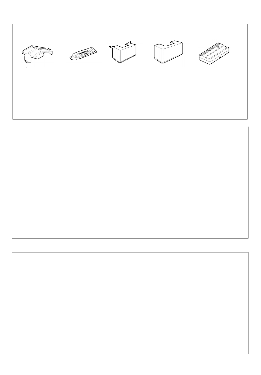
Light Lenses (2)
Model 1160 and
Model 1150
OPENER CARTON INVENTORY: Your garage door opener is packaged in two cartons which contain all parts
illustrated below and on page 26. Hardware for assembly and installation are listed below.
Sprocket
Cover
6 lock washers, 5/16
6 nuts, 5/16"-18 x 1/2"
2 carriage bolts, 5/16"-18 x 2-1/2"
4 screws, 5/16"-18 x 7/8"
4 lag screws 5/16" x 1-7/8"
Rail Grease
HARDWARE BAG CONTENTS
2 clevis pins, 5/16"-1"
1 clevis pin, 5/16"-2-3/4"
2 screws, 6ABx1" slotted pan head
3 ring fasteners
Anchors (2)
Light Lens (1)
Model 1145
FEATURES OF YOUR OPENER
1. Opener Light(s): Turns on and off automatically with 4 1/2
minute illumination for your safety and convenience. On Models
1160 and 1150, Light switch feature on Multi-Function Control
Panel can be activated for constant light. (Optional
accessory available for other models.)
2. Lock Switch Feature - (Standard on Models 1160, 1150;
optional on other models): When Lock Switch feature is activated
on the Multi-Function Control Panel, the opener will not operate
from portable remote control transmitters. The door will OPEN
from the door control button, Key Switch and Wireless Keyless
Entry System accessories, described below.
Door will CLOSE if door button is pressed and held through a
complete down cycle. If the door button is released before
travel is complete door
will reverse.
Remote Control
Transmitter (1)
Insulated staples
Manual release rope
Manual release handle
Handy Hints label
3. Safety System: Independent up and down force adjustment.
The door REVERSES automatically when obstructed in
direction. The door STOPS when obstructed in UP direction.
4. Manual Release Handle: Pull cord disconnect permits manual
door operation in case of an emergency or power failure.
5. Automatic Reconnect: Trolley halves reconnect for automatic
operation when opener is activated after a manual disconnect.
6. Motor Power: Permanently lubricated motor with automatic
reset.
7. Digital Radio Controls: Codes can be set and changed easily
and as often as you would like.
8. Easy Limit Adjustment: Limits of door opening and closing
adjusted by turning screws without removing chassis cover.
SPECIFICATIONS
Type..........................................Permanent split capacitor
Speed.......................................1500 rpm
Volts .........................................120 Volts ?AC - 60 Hz. Only
Current .....................................4.5 amperes
Gears........................................16:1 worn gear reduction
Drive......................................... Full chain with two-piece trolley
on
................................................. steel T-rail
Length of travel.........................Adjustable to 7 1/2 feet
Travel rate.................................On when door starts to travel, off 4
Door Linkage............................ Adjustable door arm. Pull cord
MOTOR
DRIVE MECHANISM
1/2 minutes after stop. Models
1160 and 1150 have separate
Light Switch feature.
trolley release.
SAFETY
Personal................................... Push button and automatic
reversal in down direction. Push
button and automatic stop in UP
direction.
Electronic..................................Independent UP and DOWN
force adjustment screws.
Electrical...................................Motor overload protector and low
voltage push button wiring.
Limit device..............................Circuit actuated by limit nut
Limit adjustment...................... .Screwdriver adjustment on side
panel.
Start circuit............................... Low voltage push button or
radio control.
DIMENSIONS
Length (overall)........................ 124 inches
128 inches (Models 1160, 1150)
Headroom required.................. 2 inches
Hanging weight........................ 32 pounds
3
Page 4
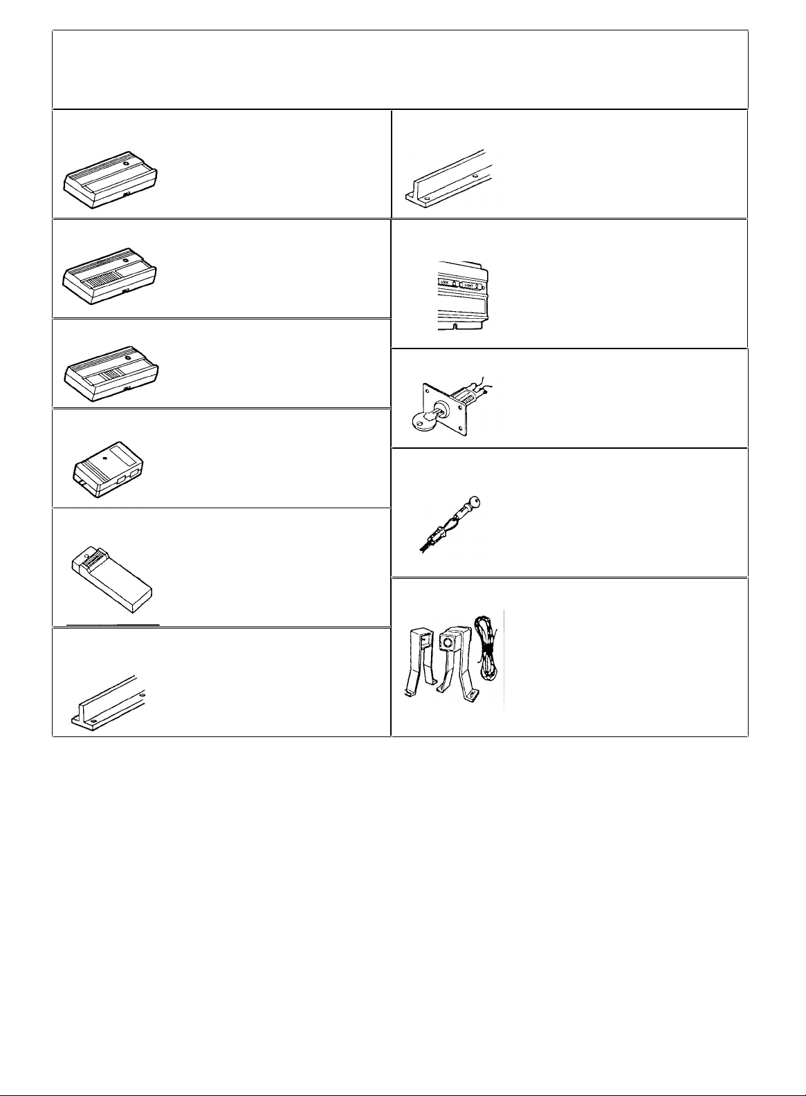
ACCESSORIES
10-FT T-RAIL:
OUTSIDE KEYLOCK:
Many useful accessories are available for your garage door opener. They are illustrated below with model numbers and
descriptions.
Model 61LM
STANDARD REMOTE CONTROL
TRANSMITTER:
Single-Function with visor clip
.
Model 1710
Fully assembled 10-ft. T-rail with full
chain. Allows 10-foot garage doors
to open fully
Model 62LM 2-CHANNEL REMOTE CONTROL
TRANSMITTER:
With visor clip.
Model 63LM
Model 64LM
Model 66LM
Model 1708
MULTI-FUNCTION REMOTE
CONTROL TRANSMITTER:
With visor clip.
MINI MULTI-FUNCTION REMOTE
CONTROL TRANSMITTER:
With key ring.
KEYLESS ENTRY SYSTEM:
Enables homeowner to operate
garage door opener from outside by
entering code on specially designed
keypad.
8-FT T-RAIL:
Fully assembled 8-ft. T-rail with full
chain. Allows 8-ft. garage doors to
open fully
Model 56
Model 60
Model 1702
Model 70
MULTI-FUNCTION CONTROL
PANEL:
Provides a Lock Switch feature
which prevents operation of garage
door opener from remote control
transmitters and a Light Switch
feature for constant light.
Opens garage door automatically
from outside when transmitter is not
handy
OUTSIDE QUICK RELEASE
LOCK:
REQUIRED for a garage with NO
service door.
Allows manual operation of garage
door from outside in case of power
failure .
"THE PROTECTOR SYSTEM":
Provides auxiliary support to the safety
features built into your opener. The
system's invisible beam, when broken by
an obstruction, causes a closing door to
open and prevents an open door from
closing. Strongly recommended for
homeowners with young children.
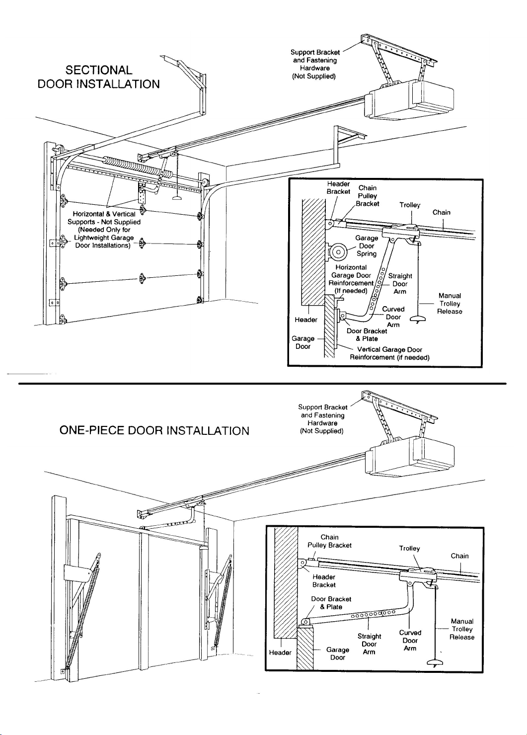
BEFORE YOU BEGIN, PLEASE TAKE SOME TIME TO CAREFULLY EXAMINE THE
ILLUSTRATIONS ON THE FOLLOWING PAGE OF A TYPICAL GARAGE DOOR OPENER
INSTALLATION ON BOTH A SECTIONAL AND A ONE-PIECE DOOR.
Some installation instructions vary for sectional and one-piece doors. Follow only those
instructions which apply to your door type.
Do you have a finished ceiling in your garage? If so, you will need a support bracket
and additional fastening hardware. Refer to Step 4, Page 13 for specific requirements.
Do you have a lightweight or metal door (or does it have glass panels)? If so,
horizontal and vertical reinforcement is required. Refer to Step 8, Page 17.
4
Page 5
5
Page 6
Operation of Your Opener
HOW THE DOOR MOVES WHEN THE OPENER IS
ACTIVATED
3. If opening, the door will stop (allowing space for entry
and exit of pets and for fresh air).
7. The optional Protector System uses an invisible beam
which, when broken by an obstruction, causes a closing door
from closing door to open and prevents an open door from
closing. It is STRONGLY RECOMMENDED for homeowners
with young children.
CAUTION
• BEFORE YOU PROCEED, PLEASE READ THE SAFETY
RULES ON PAGE 2 AND OPERATING INSTRUCTIONS
ON THIS PAGE CAREFULLY.
• T0 AVOID DIFFICULTY DURING INSTALLATION, DO NOT
RUN OPENER UNTIL INSTRUCTED TO DO SO.
HOW TO ACTIVATE THE OPENER
Use any of Operation following devices:
1. The Remote Control Transmitter. Hold the push
button down until the door starts to move.
2. The Door Control Button. Hold the button down until
the door starts to move.
3. The Outside Keylock or Keyless Entry System (if
you have installed either of these accessories).
HOW TO OPERATE THE DOOR MANUALLY
THE DOOR SHOULD BE FULLY CLOSED IF POSSIBLE.
WEAK OR BROKEN SPRINGS COULD ALLOW AN OPEN
DOOR TO FALL RAPIDLY. PROPERTY DAMAGE OR
SERIOUS PERSONAL INJURY COULD RESULT. DO
NOT USE THE MANUAL RELEASE HANDLE TO PULL
THE DOOR OPEN OR CLOSED.
• DO NOT PERMIT CHILDREN TO PLAY IN DOOR AREA.
• OPERATE ONLY WHEN OPENER IS PROPERLY
ADJUSTED AND THE DOOR IS VISIBLE AND
UNOBSTRUCTED.
OPENER LIGHT(S) will turn on under the following
conditions: when the opener is initially plugged in; when
the power is interrupted; when the opener is activated.
4 1/2
Light(s) turns off automatically after
minutes. Bulb
size is 75 Watts maximum. If the Multi - Function Control
Panel (with the Light Switch Feature) is installed, the light
can remain ON or turn OFF before the automatic cycle is
completed, if desired.
1. If open, the door will close. If closed, the door will
en.
o
2. If closing, the door will reverse.
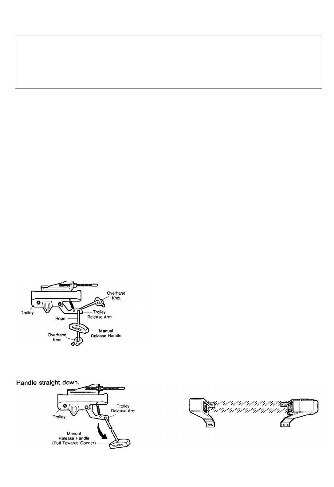
Disconnect the door from the opener by pulling down
sharply on the red handle. Lift the door manually. To
automatically reconnect the door to the opener, press the
Door Control Button.
LOCKOUT FEATURE: prevents the trolley from
reconnecting automatically. If you need to use this feature,
pull the Manual Release Handle down and back (toward the
opener). Trolley will remain “Locked-Out” and the door can
be raised and lowered manually. To reconnect trolley, pull
the Manual Release Handle straight down.
4. If the door has been stopped in a partially open
position, it will close.
5. If an obstruction is encountered while closing, the door
will reverse.
6. If an obstruction is encountered while opening, the door
will stop.
6
Page 7
CARE OF THE OPENER
When properly installed, opener will provide high
performance with a minimum of maintenance. The opener
does not require additional lubrication.
Most complaints of unsatisfactory opener operation can
be traced to problems with the door itself. When operated
manually, a properly balanced door will stay in any point
of travel while being supported entirely by its springs.
THE OPENER IS NOT INTENDED TO CORRECT ANY
PROBLEMS THAT ARE CAUSED BY AN UNBALANCED
OR BINDING DOOR, BROKEN DOOR SPRINGS OR BY
FAULTY DOOR HARDWARE.
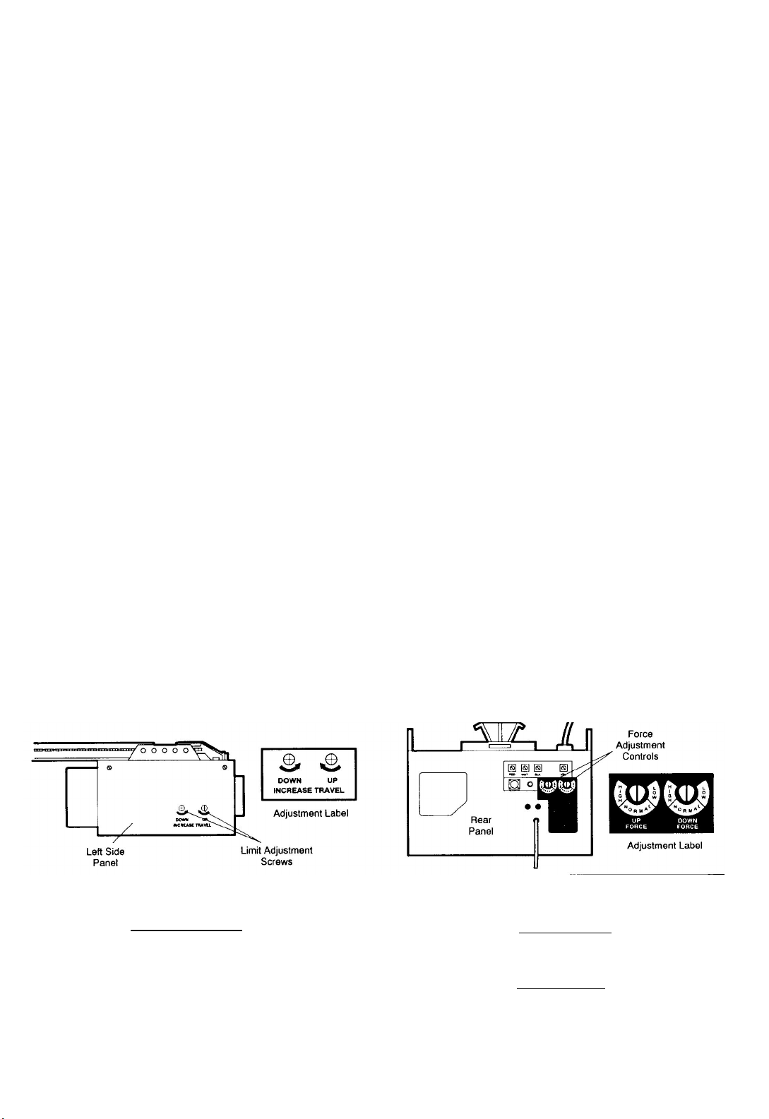
LIMIT AND FORCE ADJUSTMENTS: These adjustments
must be checked and properly set when opener is installed.
Only a screwdriver is required. Pages 20 and 21 refer to the
limit and force adjustments. Follow the instructions carefully.
REPEAT THE SAFETY REVERSE TEST AFTER ANY
ADJUSTMENT. Weather conditions may cause some
minor changes in the door operation, requiring some
readjustments, particularly during the first year of
operation.
THE SAFETY REVERSE SYSTEM IS IMPORTANT (SEE
GARAGE DOOR MUST REVERSE ON CONTACT WITH
A 1-lNCH OBSTACLE PLACED ON THE FLOOR.
FAILURE TO PROPERLY ADJUST OPENER MAY
RESULT IN SERIOUS PERSONAL INJURY FROM A
CLOSING GARAGE DOOR.
CHAIN TENSION ADJUSTMENT: After installation of the
opener and adjustment of forces and limits, the chain may
appear loose. This is normal.
TO CHECK THE CHAIN TENSION: Disconnect the trolley
by pulling the red handle. If the chain returns to the
position described and illustrated in Step 3 page 9, DO
NOT make ANY further adjustments.
REMOTE CONTROL TRANSMITTER: The portable
remote control may be secured to a car sun visor with the
clip provided. Additional remotes can be purchased at any
time for use in all vehicles using garage. Refer to
Accessories on page 4.
Any new remotes must be set to the same code as the
original remote. Code setting procedures are described on
page 23.
REMOTE CONTROL BATTERY: The 12 Volt battery
should produce power for at least one year. As long as
there is adequate power, the transmitter battery test light
will glow when the push button is pressed (and the opener
will operate). When the light becomes dim or does not
come on, replace the battery. If transmission range
lessens, check the battery test light.
TO CHANGE BATTERY: Slide the battery compartment
cover back. Discard the old battery and Position the new
battery as indicated on the case.
MAINTENANCE OF YOUR OPENER
ONCE A MONTH
MANUALLY OPERATED DOOR. If it is unbalanced or
binding, call for professional garage door service.
CHECK TO BE SURE DOOR OPENS & CLOSES FULLY.
Adjust Limits and/or Force if necessary.
REPEAT SAFETY REVERSE TEST. Make any necessary
adjustments (See Page 22).
TWICE A YEAR
CHECK CHAIN TENSION. Adjust if necessary.
ONCE A YEAR
OIL DOOR ROLLERS, BEARINGS AND HINGES.
7
Page 8
ASSEMBLY STEP 1
TO AVOID INSTALLATION DIFFICULTIES,
DO NOT RUN OPENER UNTIL YOU ARE
INSTRUCTED TO DO SO.
USE ONLY THOSE SCREWS MOUNTED IN
TOP OF OPENER. FAILURE TO DO SO
WILL CAUSE SERIOUS DAMAGE TO THE
DOOR OPENER.
Attach T-Rail To Opener
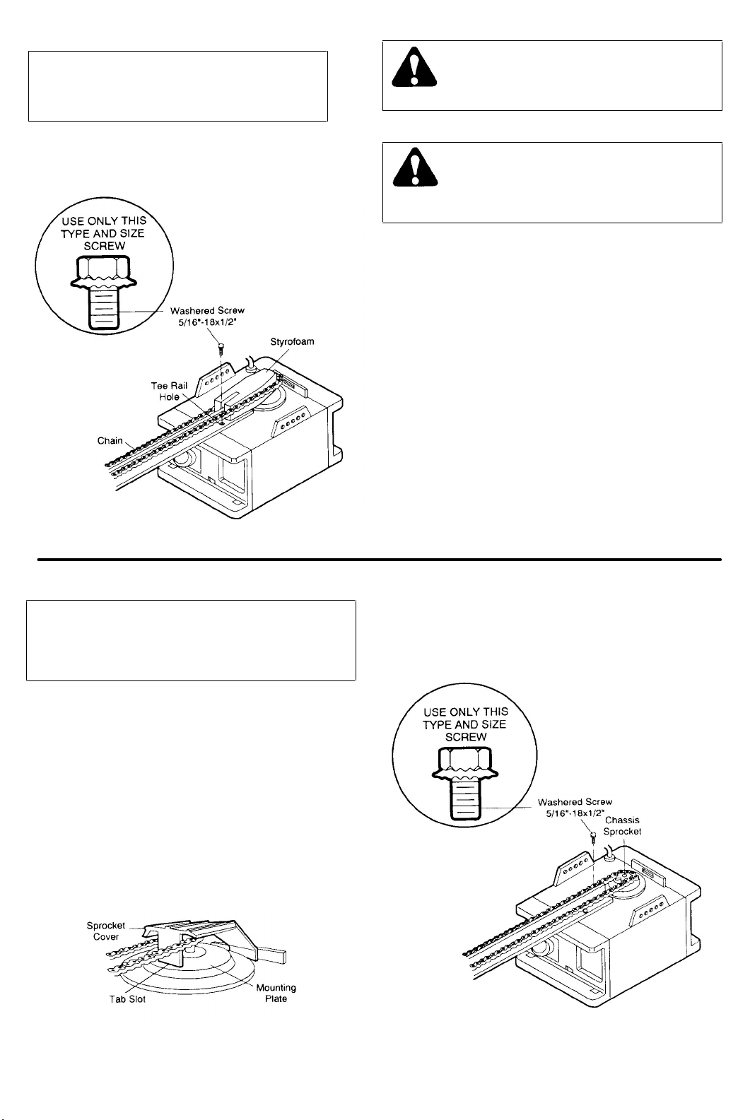
PROCEDURE: remove the two washered screws mounted
in top of opener. Position T-Rail at a 45 degree angle to
opener so one hole in T-rail and opener line up. Thread one
of the washered screws part way in.
CAUTION: USE ONLY THESE SCREWS! Use of any
other screws will cause serious damage to door
opener.
Align T-rail and styrofoam over opener sprocket. Cut tape
from T-rail, chain and styrofoam.
REMOVE STYROFOAM. Proceed to Step 2.
ASSEMBLY STEP 2
Attach Chain to Sprocket
PROCEDURE: Position chain over opener sprocket. If
necessary, loosen inner nut on trolley to obtain more
chain slack. Insert second washered screw.
CAUTION: Use only the screw previously removed
from opener
Tighten both screws securely through the T-rail into
opener as shown.
Insert back tab of sprocket cover in slot; then bend the
cover forward and insert front tab in slot provided on
mounting Plate.
8
Page 9
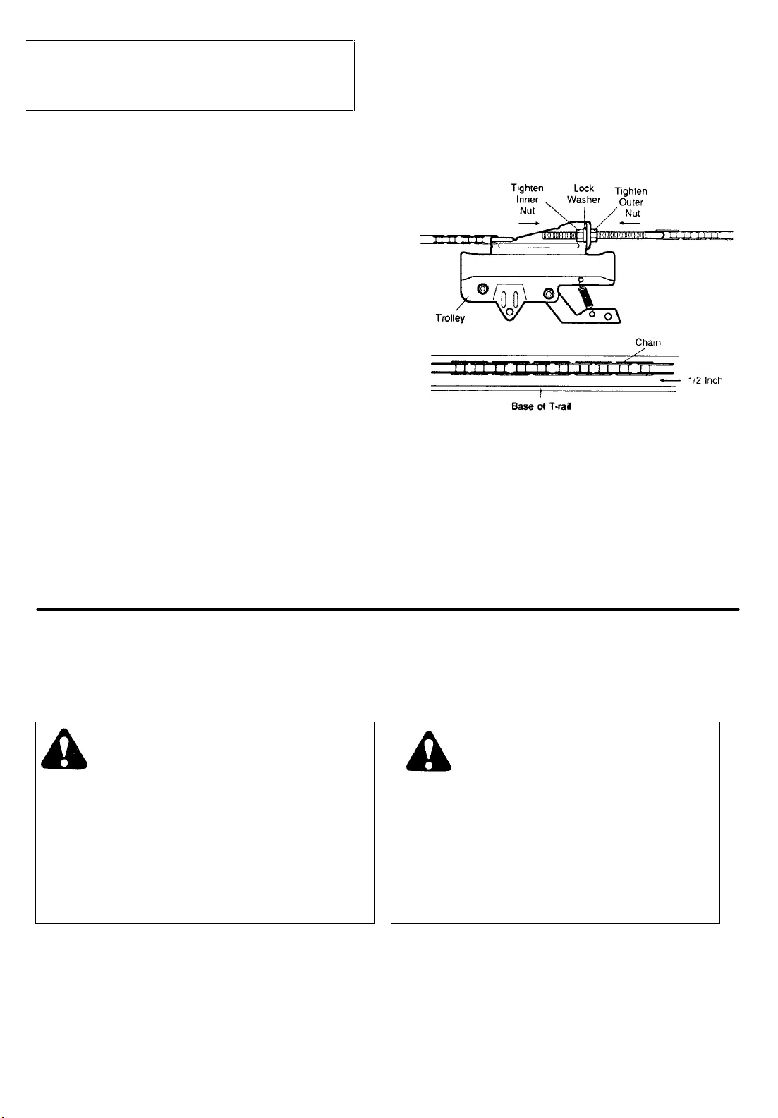
ASSEMBLY STEP 3
Tighten the Chain Assembly
CAUTION: Keep the chain from twisting as nuts are
turned
PROCEDURE: Thread inner nut on the trolley in the
direction shown. Loosen outer nut, if necessary.
Tension is correct when the chain is approximately 1/2"
above the base of the T-rail, midway between the pulley
bracket and the opener.
To maintain proper tension, tighten outer nut as shown
Sprocket noise can result if chain Is either too loose
or too tight.
CAUTION: Do not overtighten the chain. Refer to
Page 7.
ASSEMBLY OF YOUR GARAGE DOOR OPENER IS NOW COMPLETE
BEFORE BEGINNING THE INSTALLATION OF YOUR GARAGE DOOR OPENER, BE SURE TO
COMPLY WITH ALL THE SAFETY RULES.
KEEP GARAGE DOOR BALANCED.
STICKING OR BINDING DOORS MUST BE
REPAIRED. THE GARAGE DOOR, DOOR
SPRINGS, CABLES, PULLEYS, BRACKETS
AND THEIR HARDWARE ARE UNDER
EXTREME TENSION AND CAN CAUSE
SERIOUS PERSONAL INJURY. DO NOT
ATTEMPT TO LOOSEN, MOVE OR
ADJUST THEM. CALL FOR GARAGE
DOOR SERVICE
DO NOT WEAR WATCHES, RINGS OR
LOOSE CLOTHING WHILE INSTALLING
OR SERVICING A GARAGE DOOR
OPENER.
IT IS RECOMMENDED THAT THE GARAGE DOOR OPENER BE INSTALLED 7 FEET OR MORE ABOVE THE
FLOOR. WHERE SPACE PERMITS.
9
Page 10
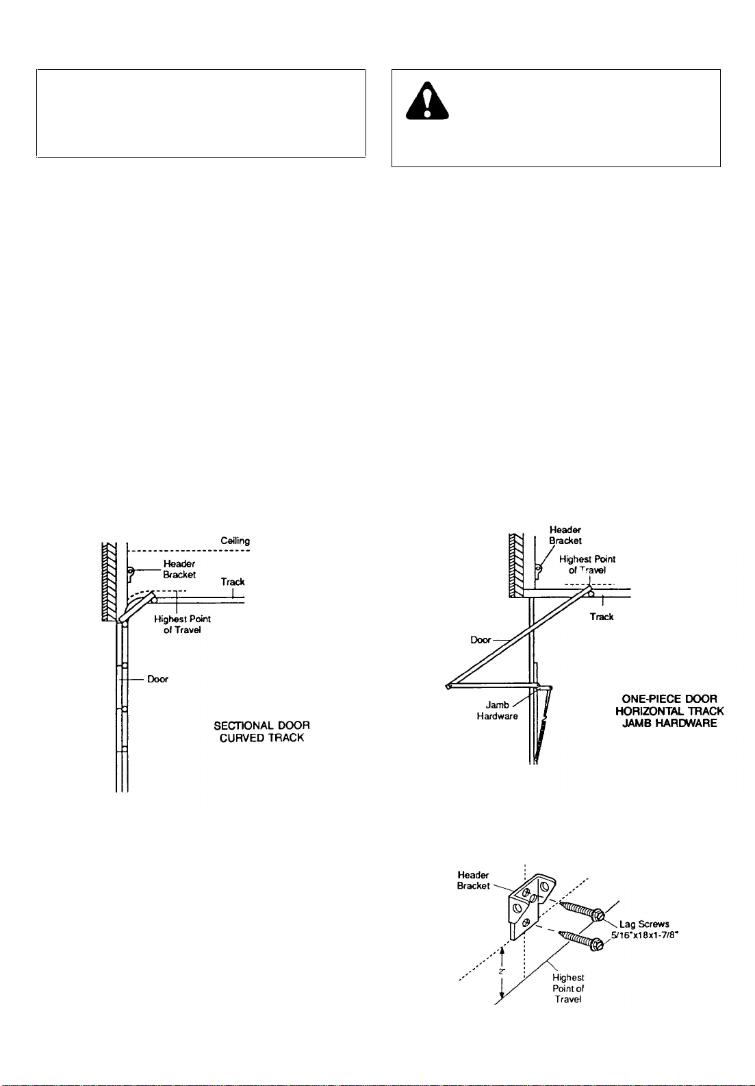
INSTALLATION STEP 1
Position and Install Header Bracket
Installation procedures vary according to garage
door types. Follow the instructions which apply to
your door.
SECTIONAL DOOR & 1-PIECE DOOR WITH TRACK
THE HEADER BRACKET MUST BE RIGIDLY
FASTENED TO HEADER WALL. REINFORCE
WALL WITH A 2x4 I F NECESSARY. FAILURE T O
COMPLY MAY RESULT IN IMPROPER
OPERATION OF SAFETY REVERSE SYSTEM
(SEE PAGE 22).
1. Close door and mark the inside vertical centerline of
garage door. Extend the line onto header wall above
door.
2. Open door to highest point of travel as shown. Draw
an intersecting horizontal line on header wall 2" above
high point. This height will provide travel clearance for
top edge of door.
NOTE: When the headroom is not sufficient for 2"
clearance, the bottom edge of bracket may be placed
in line with the door's high point of travel.
3. Position bracket as shown (centered on vertical
guideline with bottom edge of bracket on horizontal
line).
Mark either top and bottom or left and right bracket
holes. Drill 3/16"
pilot holes and fasten bracket.
Page 11
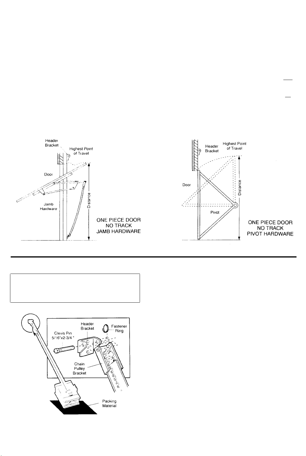
ONE-PIECE DOOR WITHOUT TRACK
EXAMPLE
PLEASE READ AND COMPLY WITH THE WARNINGS ON PAGE 10. THEY APPLY TO THE INSTALLATION OF
THE HEADER BRACKET REGARDLESS OF DOOR TYPE.
1. Close door and mark inside vertical centerline of
garage door. Extend line onto header wall above
door.
2. Open door to highest point of travel as shown.
Measure the distance from top of door to floor.
Subtract actual height of door. Add 8" to remainder
(See Example).
NOTE: If the total number of inches exceeds height
available In garage, use the maximum height
possible. On finished ceilings, do not position the
bracket closer than 1/2" from ceiling.
Distance from top of door (at
highest point of travel) to floor
................................................................................92”
Actual height of door ..............................................-88”
Remainder.................................................................4"
Add .........................................................................+8
Bracket height on header wall ...............................=12”
(Measure UP from top of CLOSED door.)
POSITION AND FASTEN HEADER BRACKET AS
DESCRIBED AND SHOWN IN NO. 3 ON PAGE 10.
INSTALLATION STEP 2
Attach the T-Rail to Header Bracket
PROCEDURE: Position opener on garage floor below
header bracket. Use packing material as a protective
base.
NOTE: To enable T-rail to clear sectional door
springs, it may be necessary to lift opener onto a
temporary support.
CAUTION: The opener must either be secured to a
support or held firmly In place by another person.
Raise T-rail until pulley and header brackets come
together. Align bracket holes and join with clevis pin as
shown. Insert ring fastener to secure.
11
Page 12
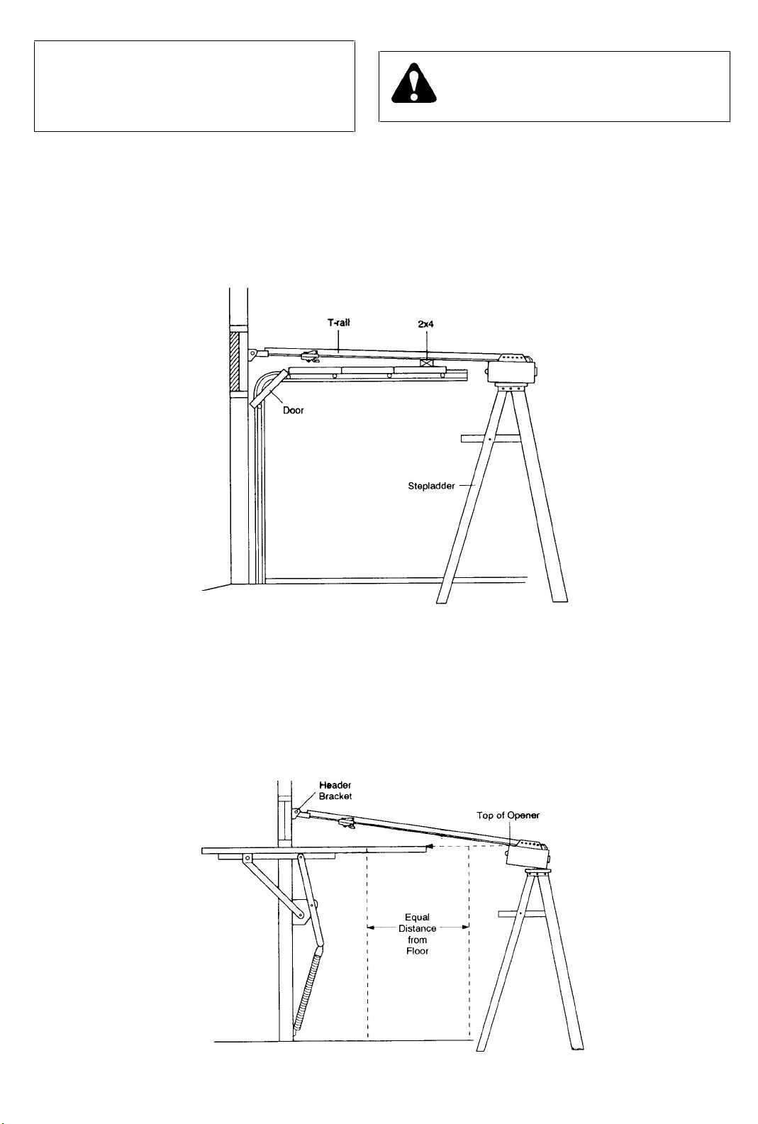
INSTALLATION STEP 3
Position the Opener
Follow instructions which apply to your door
type as illustrated.
INSTALLATION-SECTIONAL DOOR & 1-PIECE DOOR WITH TRACK
TO PREVENT DAMAGE TO LIGHT WEIGHT
DOORS AND/OR DOORS WITH WINDOWS, DO
NOT REST THE OPENER ON THE DOOR.
NOTE: A 2 x4 is convenient for setting an ideal door
to T-rail distance. It is not necessary where
headroom is insufficient.
PROCEDURE: Raise the opener onto a stepladder. Open
garage door. Place a 2x4 on the top section of door near
centerline as shown. Rest T-rail on 2x4 as shown.
INSTALLATION - 1-PIECE DOOR WITHOUT TRACK
PROCEDURE: Measure the distance from floor to top of
door (in fully open position and parallel to the floor). Using
a stepladder as a support, raise opener to the same
distance from the floor (it will have a slight angle as
shown).
The top of the door should be level with the top of
opener. For maximum efficiency, do not position opener
more than 2 inches above this point.
12
Page 13
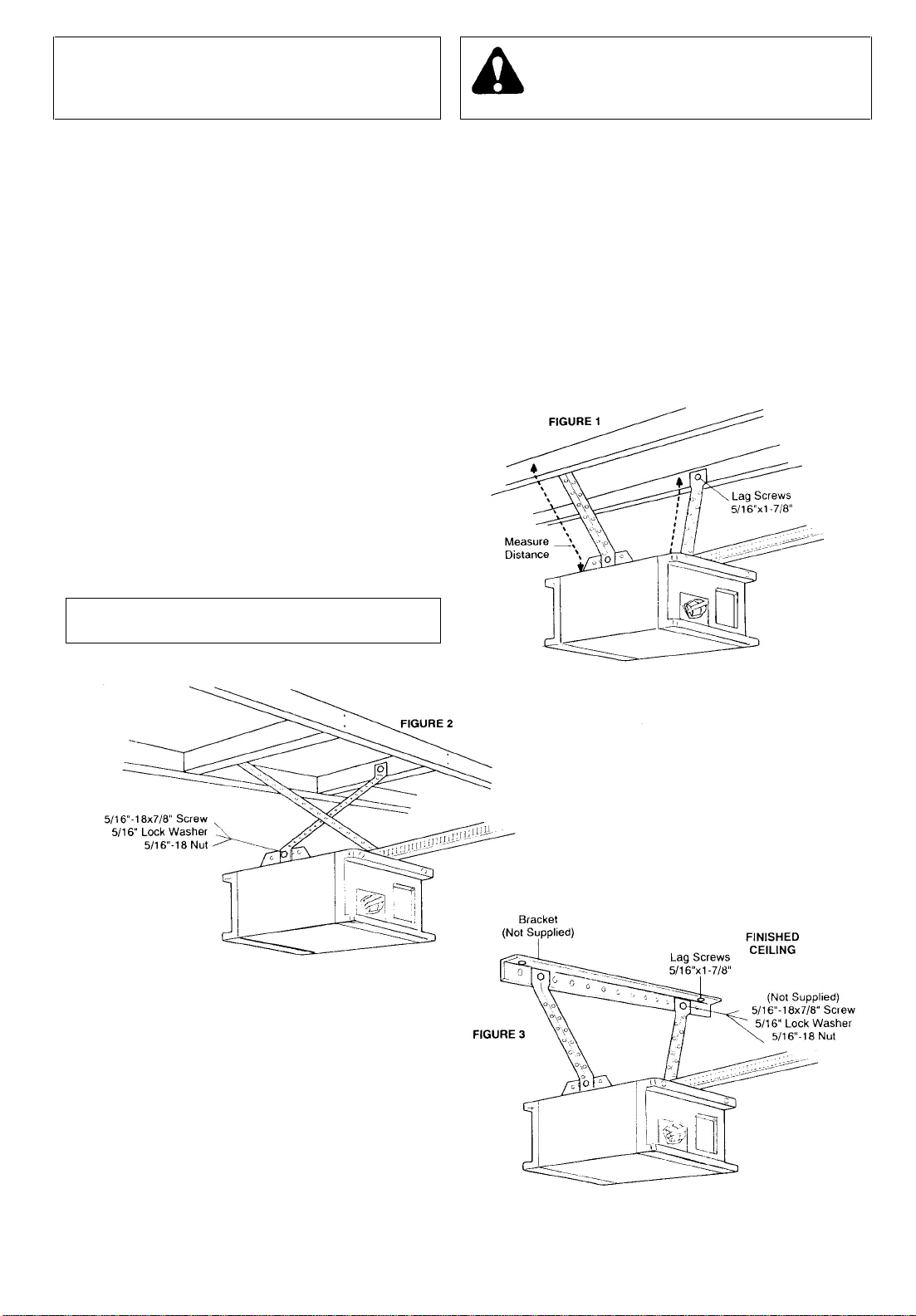
INSTALLATION STEP 4
Three representative installations are shown. Yours may be different. Hanging brackets should
be angled (Fig.1) or crossed (Fig.2) to provide rigid support. On finished ceilings (Fig.3), attach a
sturdy metal bracket (not supplied) to ceiling joists before installing opener.
Hang the Opener
PROCEDURE: Measure the distance from EACH side of
the opener to the structural support.
Cut both pieces of the hanging bracket to required
lengths. Flatten one end of each bracket and bend or
twist to fit the fastening angles. Do not bend at the
bracket holes. Drill 3/16" pilot holes in structural
supports. Attach flattened ends of brackets to the
supports with 5/16"x1-7/8" lag screws.
Lift opener and fasten to hanging bracket as shown.
Check to make sure the T-rail is centered over
door. REMOVE the 2x4.
Operate the door manually. If door hits the rail, raise
header bracket.
THE OPENER MUST BE SECURELY
FASTENED TO A STRUCTURAL SUPPORT
OF THE GARAGE.
Grease the top and underside of rail surface on
which trolley slides. A tube of grease is supplied.
13
Page 14
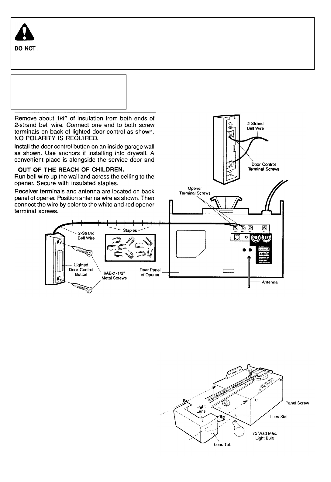
LOCATE DOOR CONTROL BUTTON (OR ANY ADDITIONAL PUSH BUTTONS) WHERE THE GARAGE DOOR IS VISIBLE.
AWAY FROM DOOR AND DOOR HARDWARE AND OUT OF THE REACH OF CHILDREN.
SERIOUS PERSONAL INJURY FROM A MOVING GARAGE DOOR MAY RESULT FROM MISUSE OF OPENER.
ALL OW CHILDREN TO OPERATE DOOR CONTROL BUTTON(S)
FASTEN THE CAUTION LABEL ON THE WALL NEAR DOOR CONTROL BUTTON AS A REMINDER OF SAFE OPERATING
PROCEDURES.
or REMOTE CONTROL TRANSMITTER.
INSTALLATION STEP 5
Install Lighted Door Control Button
Models 1156,1155, 1146,1145,1140
LIGHTED DOOR CONTROL BUTTON
Press to open or close door. Press again to
REVERSE door during the CLOSING cycle or to
STOP door during
INSTALLING LIGHT: Install a 75 watt maximum light
bulb in socket as shown. The light will turn on and
remain lit for 4-1/2 minutes when power is connected.
After 4-1/2 minutes it will turn off.
If light bulb burns out prematurely due to vibration,
replace with bulb specifically packaged for "Garage
Door Openers".
INSTALLING LENS (Models shown above except
1140): Locate (and loosen approximately 1/8") the two
screws near top of opener front panel. Position lens
against panel with slotted tabs directly below screws.
Slide lens up to seat tabs behind screws. Snap bottom
tabs of lens into panel slots. Retighten top panel screws
to secure lens.
OPERATION OF
OPENING cycle.
WIRING INSTRUCTIONS FOR ACCESSORIES
The Protector System
To white and black opener terminals
Outside Keylock
To red and white opener terminals
14
Page 15
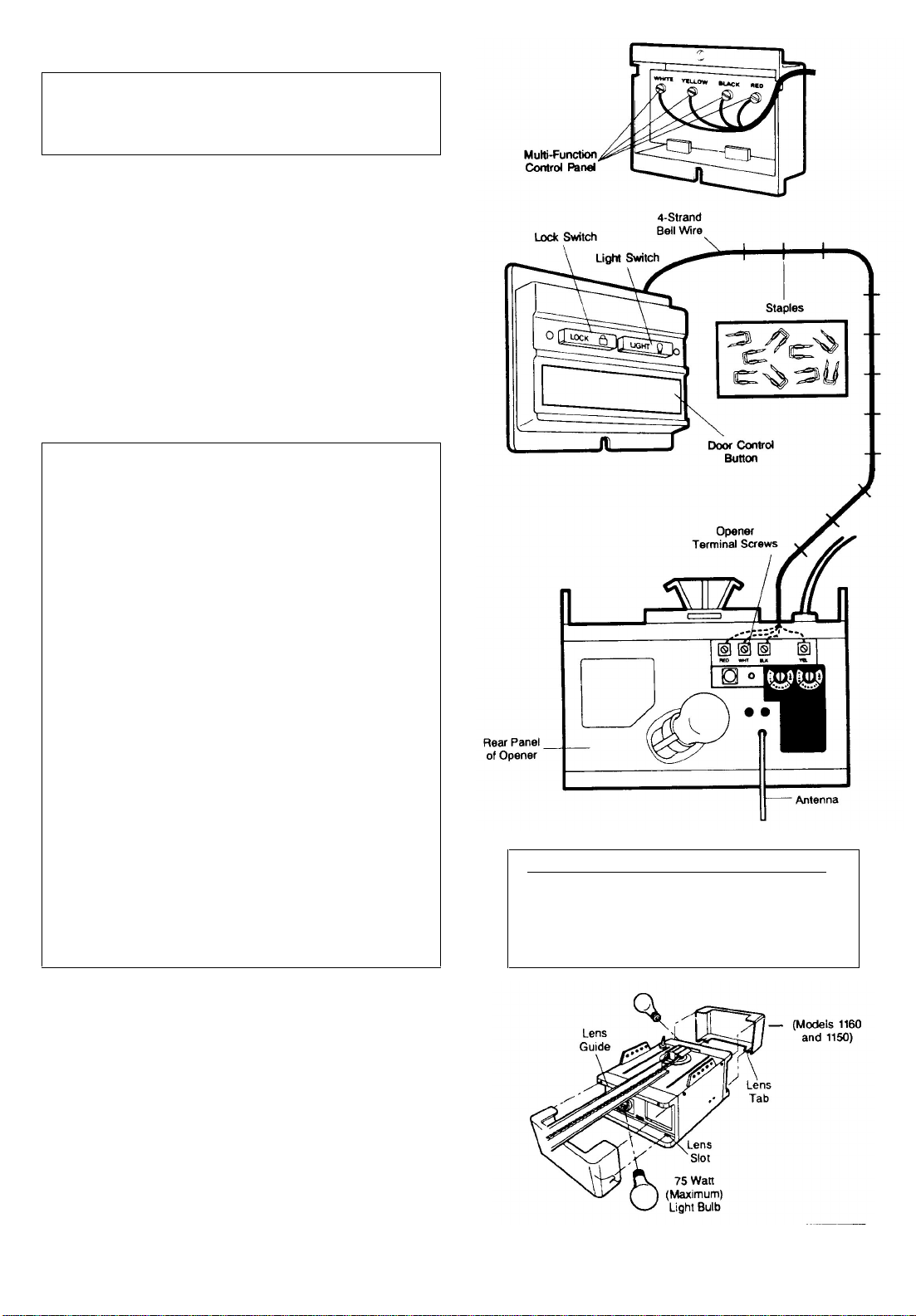
Install Multi-Function Door Control Panel
Models 1160 and 1150 ONLY
There are 4 screw terminals on the back of the Multi
Function Control. Connect bell wire by color; yellow
to yellow, white to white, red to red and black to black.
Install the Multi-Function Control on an inside garage wall as
shown. Use anchors if installing into drywall a convenient place is
alongside the service door.
LOCATE OUT OF THE REACH OF CHILDREN.
Run bell wire up the wall and across the ceiling to opener. Secure
with insulated staples.
Receiver terminals and antenna are Located on back panel of
opener. Position antenna wire as shown. Then connect the wire by
color to the red, white, black and yellow opener terminal screws.
OPERATION OF THE
MULTI-FUNCTION CONTROL PANEL
DOOR CONTROL PUSH BUTTON
Press to open or close door. Press again to REVERSE door
during CLOSING cycle or to STOP door while OPENING.
LOCK SWITCH: Activate ONLY when door is closed. The
LOCK Switch is designed to prevent operation of door from
portable remote control transmitters. Door will OPEN from Door
Control Button, Key Switch and Keyless Entry Systems. Door
will CLOSE if door control button is pressed and held until the
door closes fully. If button is released before down travel is
completed, door will reverse.
TO ACTIVATE: Press Lock Switch button. Indicator light will
turn ON. TO TURN OFF: Press Lock Switch button again.
Indicator light will turn OFF. Normal operation will
LIGHT SWITCH
TO ACTIVATE: Press Light Switch button. Indicator light will
turn ON. Opener light will turn on (or remain on if opener is still
in 41/2 minute automatic cycle). TO TURN OFF: Press Light
Switch button again. Opener light will turn OFF.
NOTE: To turn light OFF during 4-1/2 minute automatic
cycle, press Light Switch button twice • to activate and
then to turn off Light Switch Feature. Light will turn OFF
immediately.
INSTALL THE LIGHTS
Install a 75 Watt maximum light bulb in each socket. Lights will turn
ON and remain lit for 4-1/2 minutes when power is connected. Then
they will turn OFF. If bulbs burn out prematurely due to
vibration, replace with "Garage Door Opener" bulbs.
WIRING INSTRUCTIONS FOR ACCESSORIES
The Protector System
To white and black opener terminals
Outdoor Key Switch:
To red and white opener terminals
INSTALL THE LENSES
Slide lens into guides as shown. Snap bottom tabs into lens slots.
For convenience, lenses may be installed after Adjustment
Step 3, Page 22.
15
Page 16
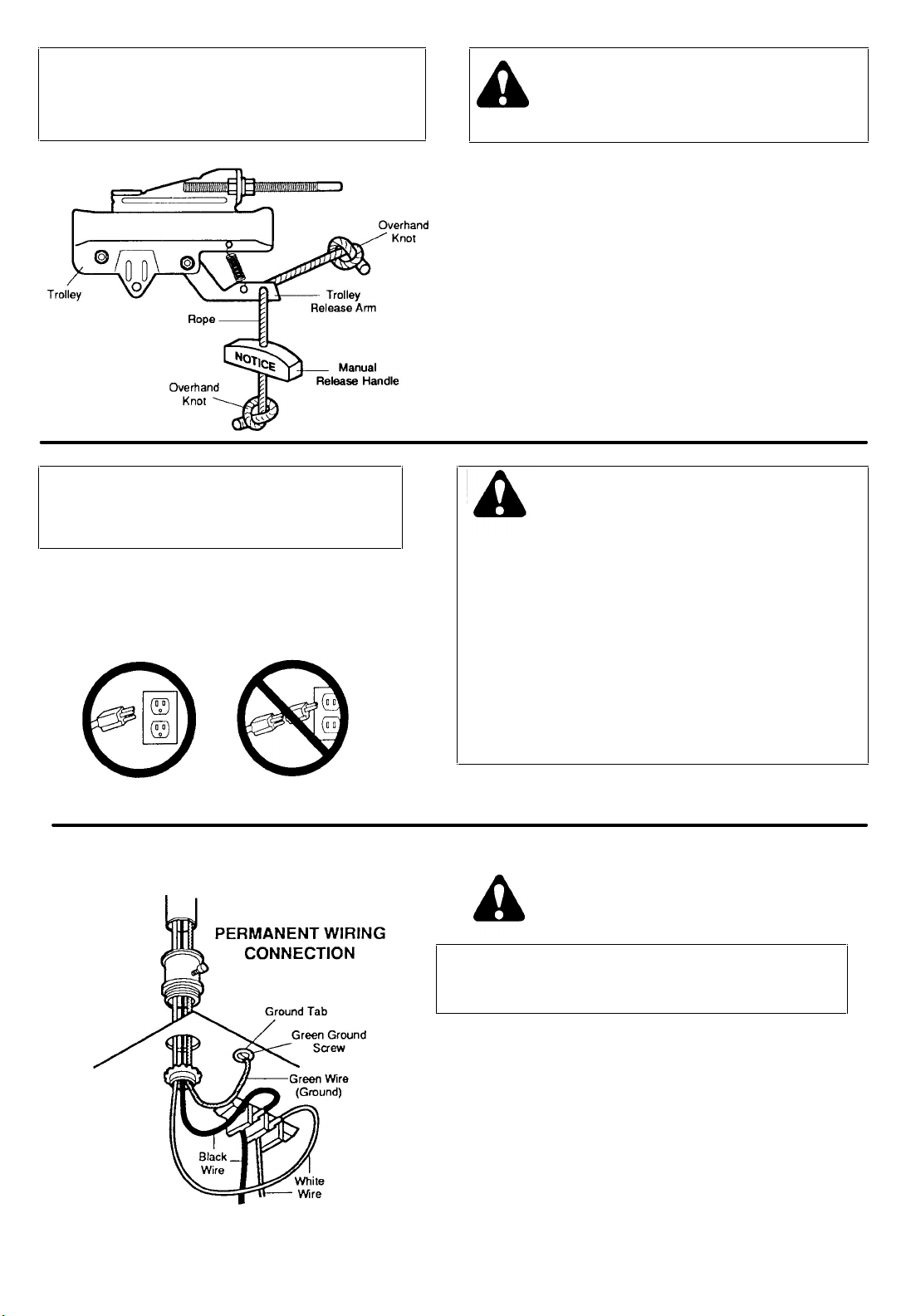
INSTALLATION STEP 6
Attach Manual Release Rope & Handle
USE MANUAL RELEASE ROPE ONLY TO
DISENGAGE TROLLEY. DO NOT USE ROPE AND
HANDLE TO PULL DOOR OPEN OR CLOSED.
PROCEDURE: Thread one end of rope through hole in top of red
handle so 'NOTICE' reads right side up as shown. Secure with an
overhand knot.
NOTE: Knot should be at least 1" from the end of the rope to
prevent slipping.
Thread other end of rope through hole in release arm of outer trolley.
Adjust rope length so that handle is 6 feet above the floor. Secure
with an overhand knot as above.
NOTE: If it is necessary to cut rope, heat seal cut end with a
match or lighter to prevent fraying and/or raveling.
INSTALLATION STEP 7
Connect Electric Power
Opener MUST be permanently wired or plugged into
a grounded 3-prong receptacle wired according to
local electrical codes. DO NOT use a 2-wire adapter.
DO NOT USE an extension cord.
RIGHT
PROCEDURE FOR PERMANENT WIRING (if required by local codes)
WRONG
TO AVOID SERIOUS PERSONAL INJURY FROM
ENTANGLEMENT, REMOVE ALL THE ROPES
CONNECTED TO GARAGE DOOR BEFORE
OPERATING OPENER.
TO AVOID DAMAGE TO GARAGE DOOR AND OPENER,
MAKE DOOR LOCKS INOPERATIVE BEFORE CONNECTING
ELECTRIC POWER. USE A WOOD SCREW OR NAIL TO
HOLD LOCKS IN "OPEN" /UNLOCKED) POSITION.
THE INSTALLATION & THE WIRING MUST BE IN
COMPLIANCE WITH LOCAL ELECTRICAL AND BUILDING
CODES.
OPERATION AT OTHER THAN 120V 60Hz WILL CAUSE
OPENER MALFUNCTION AND DAMAGE.
DISCONNECT THE POWER AT THE FUSE BOX
BEFORE PROCEEDING.
Refer to illustration. Make connection through the 7/8"
diameter hole in top of opener.
1. Remove opener cover screws and set cover aside.
2. Remove attached 3-prong cord.
3. Connect black (line) wire to black wire on terminal
block; white (neutral) wire to white terminal wire;
Green (GROUND) wire to green around screw.
CAUTION: BE SURE THE UNIT IS GROUNDED
ACCORDING TO LOCAL CODE.
IMPORTANT NOTE: TO AVOID INSTALLATION
DIFFICULTIES, DO NOT RUN OPENER NOW.
16
Page 17
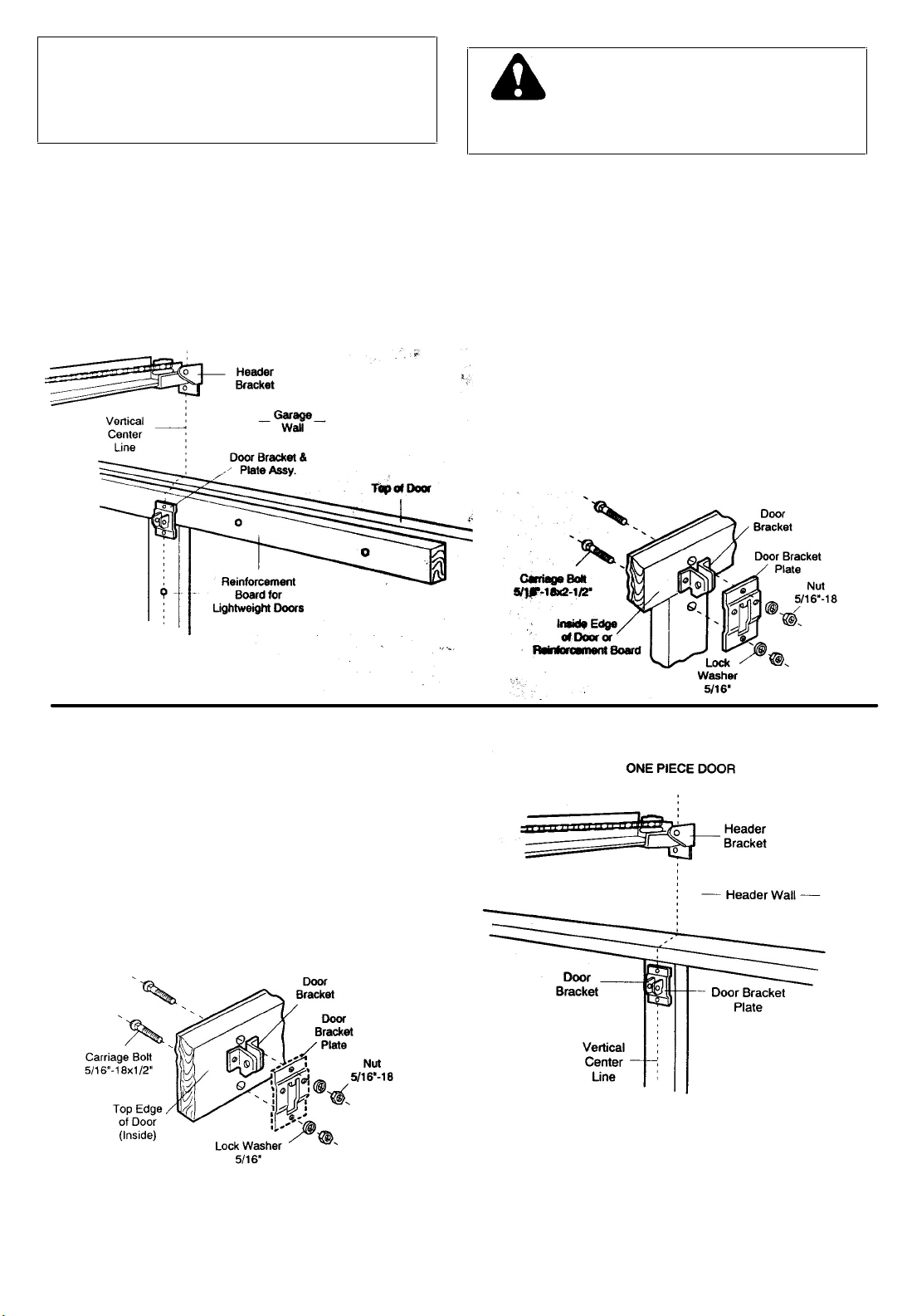
INSTALLATION STEP 8
Fasten Door Bracket and Plate
Follow instructions which apply to your door type
as illustrated below.
The horizontal brace should be at least six feet long. The
is to check with the garage door manufacturer for a door reinforcement kit to be used with an opener installation.
vertical brace should cover height of top panel. The best solution
ALWAYS REINFORCE THE INSIDE OF DOOR—
BOTH VERTICALLY AND HORIZONTALLY—WITH
2X4
TO PREVENT DAMAGE TO LIGHTWEIGHT
AND METAL GARAGE DOORS (OR THOSE
WITH GLASS PANELS),
BOARDS OR ANGLE IRON.
Sectional Door Installation Procedure
: :
Position door bracket and plate assembly against door
within the following limits according to your
requirements (and centered on vertical guideline— or
to one toot left or right of center, if necessary):
A) Top edge of bracket 2" - 4" below top edge of door.
B) Directly below any structural support across top of
door.
Mark and drill 5/16" TOP and BOTTOM fastening holes.
Secure bracket assembly as shown.
All One-Piece Door Installation Procedure
NOTE: The door bracket has left and right side
fastening holes. Assemble and Install the door
bracket and plate if your installation requires top and
bottom fastening holes.
Center bracket (with or without plate as required) at the
top of the inside face of door as shown. Mark holes.
Drill 5/16" holes and fasten the door bracket with
hardware supplied.
17
Page 18
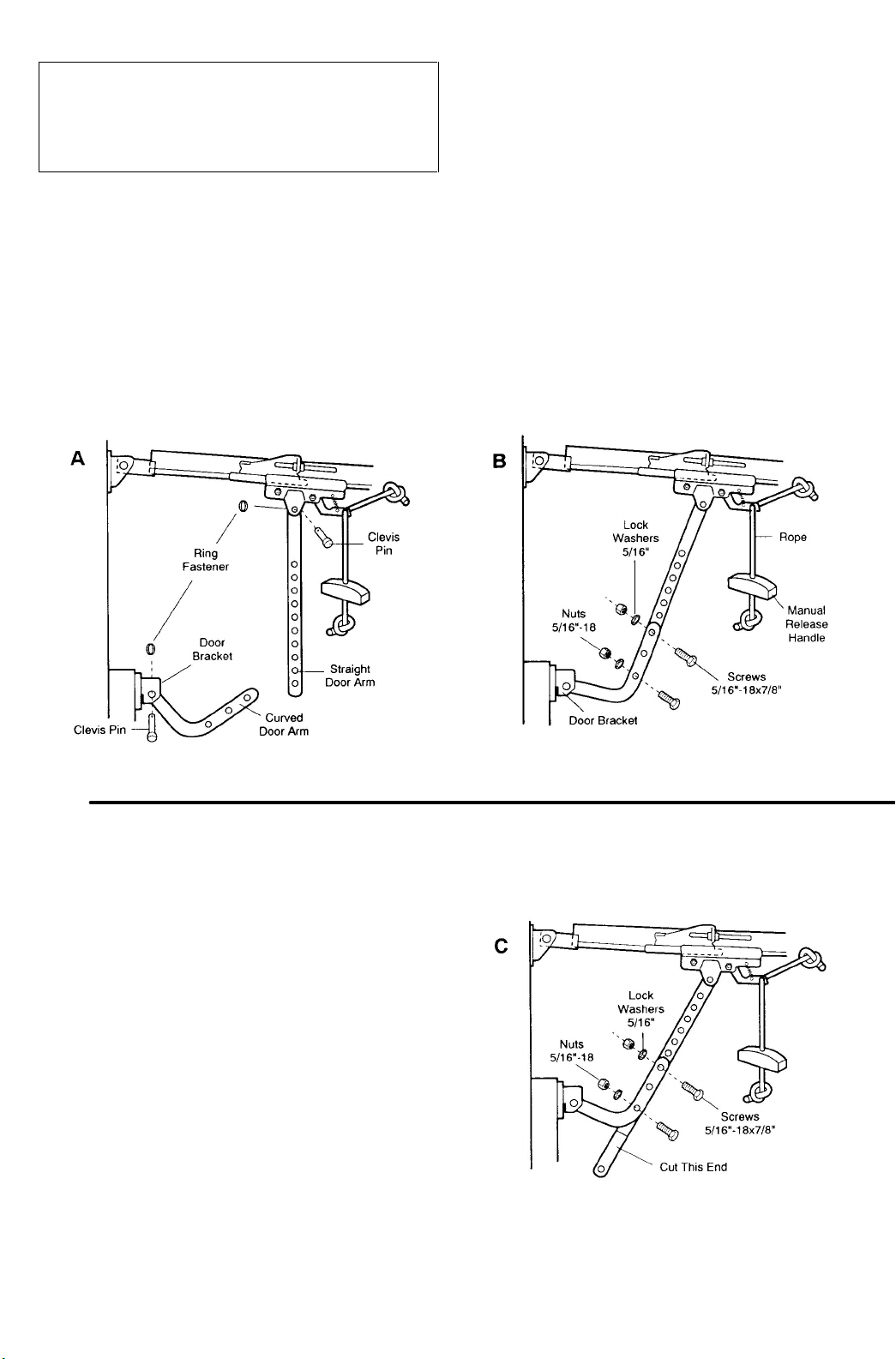
INSTALLATION STEP 9
Connect Door Arm to Trolley
Follow instructions which apply to your door
type as illustrated.
SECTIONAL DOORS INSTALLATION
Make sure garage door is closed tight. Pull the manual release handle to disconnect the trolley. Manually
move outer trolley back to the center of inner trolley as shown in Figures A, B and C.
FIG A: Fasten straight door arm section to outer trolley
with a clevis pin. Secure the connection with a ring
fastener.
Fasten curved section to the door bracket in the same
way.
FIG B: Bring arm sections together. Find two pairs of
holes that line up and join sections. Select holes as far
apart as possible to increase door arm rigidity.
FIG C: If holes in curved arm are ABOVE holes in
straight arm, disconnect straight arm. Cut about 6"
from the solid end. Reconnect to trolley with CUT END
DOWN as shown.
Bring arm sections together. Find two pairs of holes
that line up and join with screws, lock washers and
nuts.
Proceed to Step 1,
page 20. Trolley will re-engage automatically when opener is operated.
18
Page 19

ALL ONE-PIECE DOORS
ASSEMBLE DOOR ARM: Fasten straight and curved
door arm sections together to their longest possible
length. With door closed, connect straight door arm
section to door bracket with a clevis pin. Secure with a
ring fastener.
Before connecting door arm to trolley, limits of travel must be adjusted on one-piece doors. Limit
adjustment screws are located on left side panel as shown in illustration on Page 20. Follow procedures
below.
ADJUSTMENT PROCEDURES
OPEN DOOR ADJUSTMENT
Decrease UP limit. Turn UP limit adjustment screw
counterclockwise 4 complete turns.
Press door control button. Trolley will travel to full open
position.
Manually raise door arm to open position (parallel to
floor) and lift door arm to trolley. The arm should touch
trolley just in back of door arm connector hole as
shown in solid line drawing. I f arm does not extend f ar
enough, adjust limit further. One full turn equals 2" of
door travel.
CONNECT DOOR ARM TO TROLLEY: With door closed, join curved arm to connector hole in trolley with remaining
clevis pin. Secure with ring fastener. NOTE: It may be necessary to lift door slightly to make connection.
Run opener through a complete travel cycle. If door has a slight 'backward' slant in full open position, decrease UP
limits until door is parallel to floor.
Decrease DOWN limit. Turn DOWN limit adjustment
screw clockwise 8 complete turns.
Press door control button. Trolley will travel to full
closed position.
Manually close door and lift door arm to trolley. The
arm should touch trolley just ahead of door arm
connector hole as shown in dotted line drawing. If arm
is behind the connector hole, adjust limit further. One
full turn equals 2" of door travel.
19
CLOSED DOOR ADJUSTMENT
Page 20
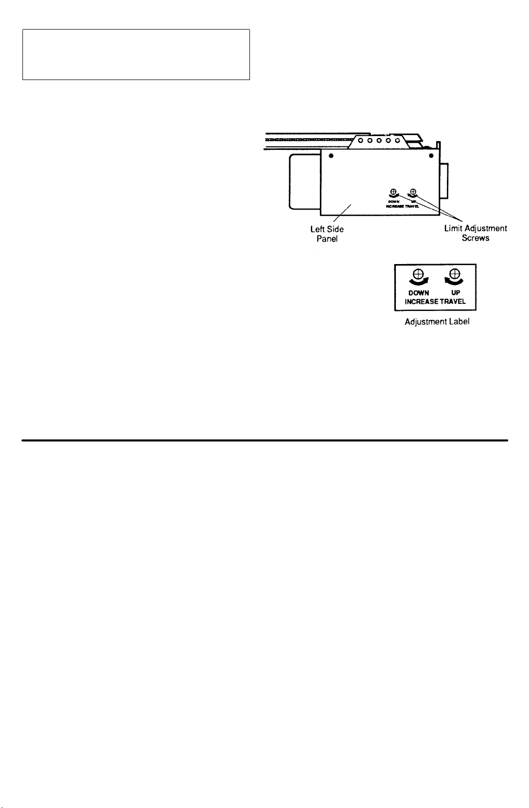
ADJUSTMENT STEP 1
A
djust UP and DOWN Limits
LIMIT ADJUSTMENT settings regulate the points at
which the door will stop when moving up or down.
NOTE: Door STOPS in the UP direction if anything
interferes with door travel. Door REVERSES in the
DOWN direction if anything interferes with the door
travel (including binding or unbalanced doors).
PROCEDURE: To operate the opener, press the Door
Control Button. Run the opener through a COMPLETE
TRAVEL CYCLE. No limit adjustments are necessary
when the door opens and closes completely and doesn't
reverse unintentionally when fully closed.
THE FOLLOWING CHART OUTLINES ADJUSTMENT PROCEDURES. RUN THE OPENER THROUGH A
COMPLETE TRAVEL CYCLE AFTER EACH ADJUSTMENT.
NOTE: REPEATED OPERATION OF THE OPENER DURING ADJUSTMENT PROCEDURES MAY CAUSE
MOTOR TO OVERHEAT AND SHUT OFF. SIMPLY WAIT 15 MINUTES AND TRY AGAIN.
Read the chart carefully before proceeding to Step 2. Use a screwdriver to make limit adjustments.
LIMIT ADJUSTMENT CHART
IF DOOR DOES NOT OPEN COMPLETELY
BUT OPENS AT LEAST FIVE FEET
Increase UP travel. Turn the UP LIMIT adjustment
screw clockwise. One turn equals 2" of travel.
If door does not open at least 5 feet: adjust UP
(OPEN) FORCE as explained in Step 2.
IF DOOR DOES NOT CLOSE COMPLETELY
Increase DOWN travel. Turn down limit adjustment
screw counterclockwise. One turn equals 2" of travel.
Increase DOWN travel. Turn down limit adjustment
screw counterclockwise. One turn equals 2 inches of
travel.
Decrease DOWN travel. Turn down limit adjustment
screw clockwise. One turn equals 2 inches of travel.
IF DOOR REVERSES WHEN CLOSING AND THERE
IS NO INTERFERENCE TO TRAVEL CYCLE
IF ONE-PIECE DOOR DOES NOT
CLOSE COMPLETELY
IF OPENER REVERSES IN FULLY
CLOSED POSITION.
If the door still will not close completely, the header
bracket is positioned too high. See Step 1, page 10.
Test door for binding: Pull manual release handle.
Manually open and close door. If door is binding, call a
door serviceman. If door is not binding or unbalanced,
adjust DOWN (CLOSE) FORCE. See Step 2.
20
Page 21
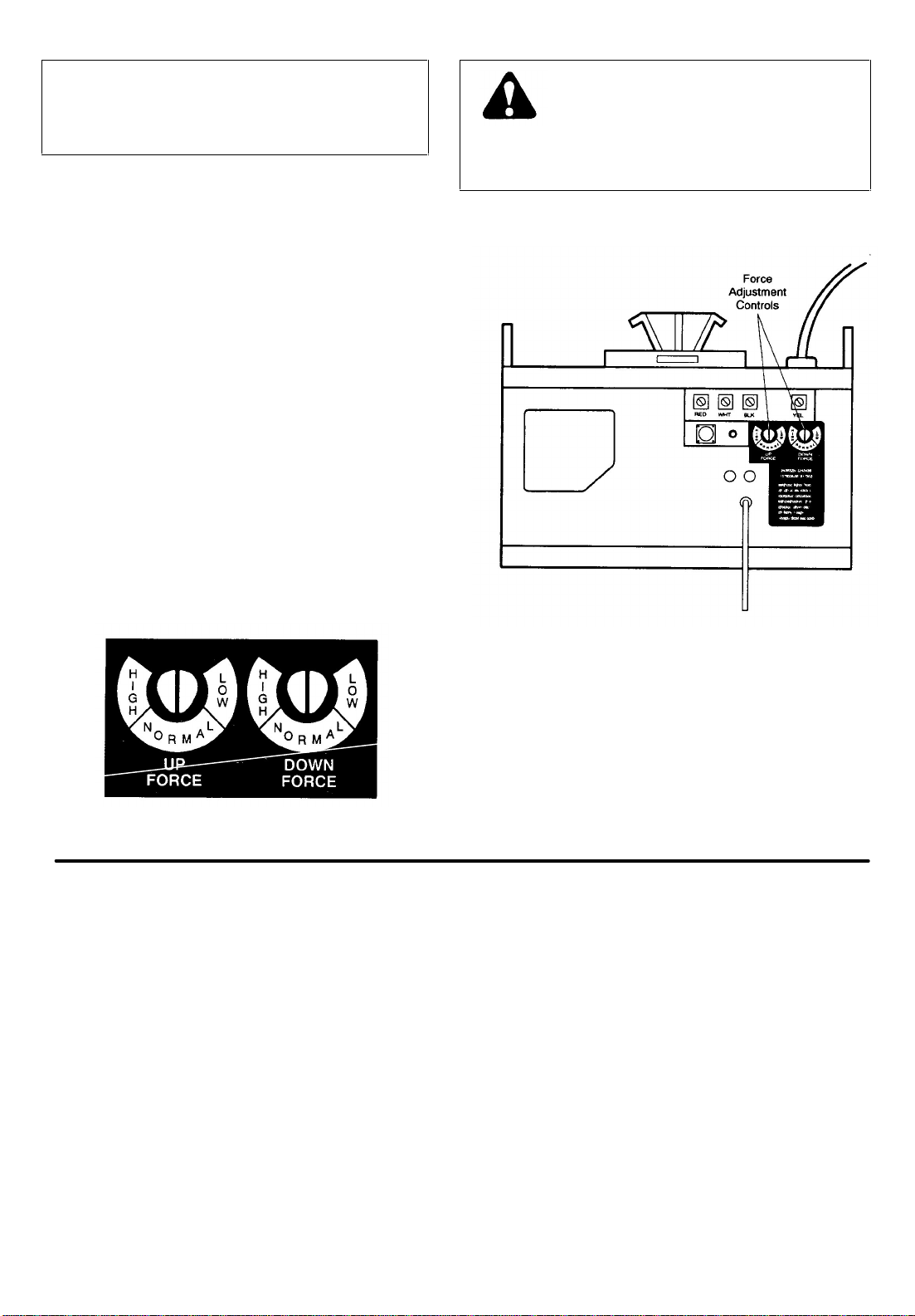
ADJUSTMENT STEP 2
A
Adjust Force
Force Adjustment Controls are located on rear panel of
opener. FORCE ADJUSTMENT settings regulate amount
of the power required to open and close door.
NOTE: The door STOPS in the UP direction if
anything interferes with its travel. Door REVERSES
in the DOWN direction if anything interferes with its
travel (including binding or unbalanced doors).
If the force adjustments are set too light, door travel ma y
be interrupted by nuisance reversals in DOWN direction
and stops in UP direction. Weather conditions can affect
the door movement, so occasional adjustment may be
needed.
Maximum force adjustment range is 260 degrees, about
3/4 of a complete turn. Do not force controls beyond that
point. Turn force adjustment controls with a screwdriver.
DO NOT USE FORCE ADJUSTMENTS TO
COMPENSATE FOR A BINDING OR
STICKING GARAGE DOOR EXCESSIVE
FORCE WILL INTERFERE WITH THE PROPER
OPERATION OF THE SAFETY REVERSE SYSTEM OR
DAMAGE THE GARAGE DOOR.
Adjustment Label
FORCE ADJUSTMENT CHART
TEST DOWN (CLOSE) FORCE
Grasp the door handle or door bottom when door is
about halfway through DOWN (CLOSE) TRAVEL. Door
should reverse. If the door is hard to hold or doesn't
reverse, decrease DOWN (CLOSE) FORCE by turning
the control in a counterclockwise direction. Make 10
degree turn adjustments until door reverses normally.
fter each adjustment, run opener through a
complete cycle.
PROCEED TO STEP 3
Increase UP (OPEN) FORCE by turning the control in a
clockwise direction. Make 10 degree turn adjustments until
door opens completely. Readjust UP LIMIT if necessary.
After each adjustment, run opener through a complete
travel cycle.
Increase DOWN (CLOSE) FORCE by turning control
clockwise. Make 10 degree turn adjustments until door
completes close cycle. After each adjustment, run the
opener through a complete travel cycle.
21
IF DOOR DOESN'T OPEN AT LEAST 5 FEET
IF DOOR REVERSES DURING DOWN
(CLOSE) CYCLE
Page 22
ADJUSTMENT STEP 3
Test Safety Reverse System
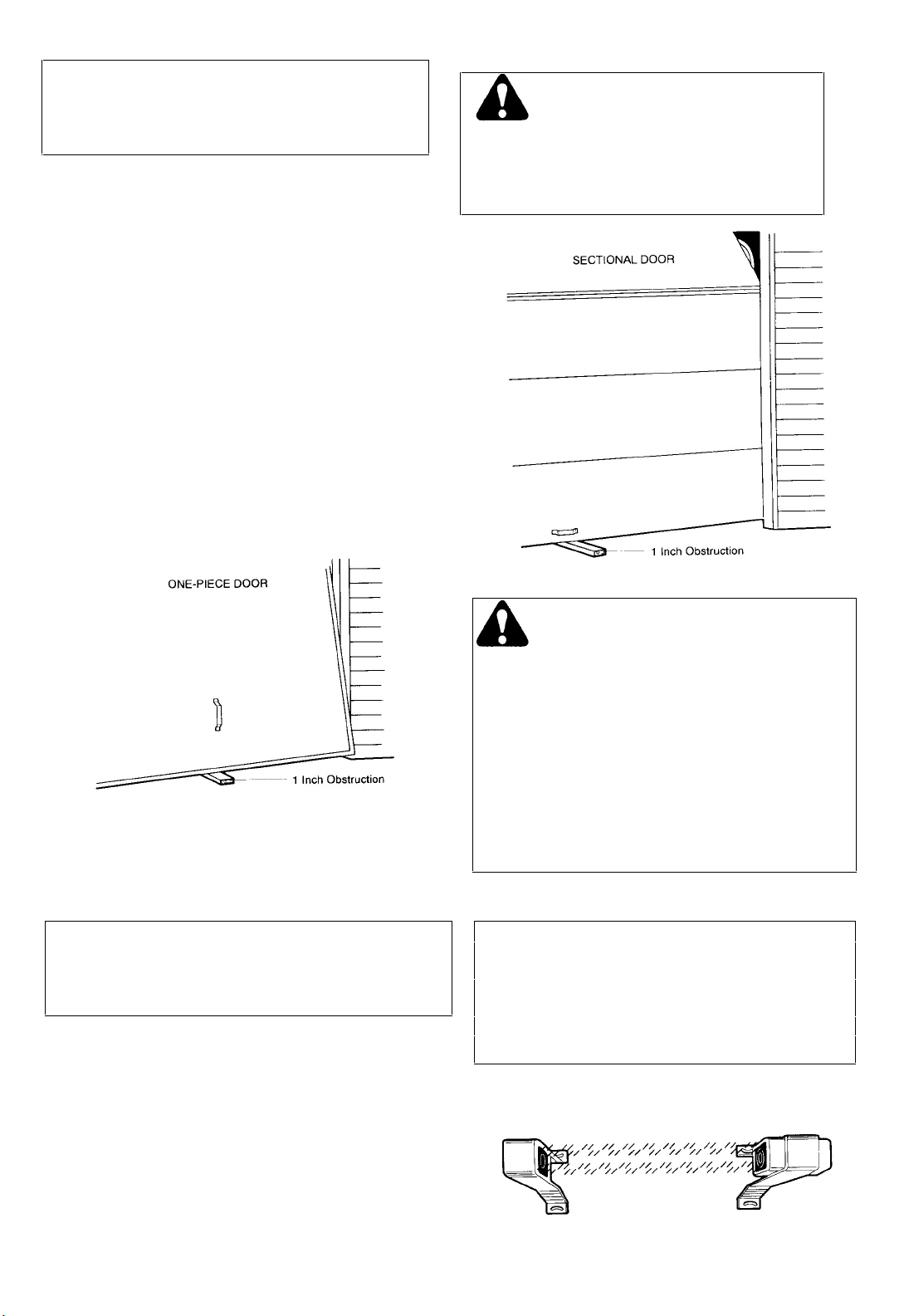
PROCEDURE: Place-a one-inch obstacle on the floor
under the garage door. Operate door in DOWN direction.
The door MUST reverse on the obstruction.
If the door STOPS on the obstruction, it is not traveling
far enough in the DOWN direction. Increase the DOWN
limit by turning DOWN limit adjustment screw
counterclockwise 1/4 turn. REPEAT TEST.
NOTE: Make sure limit adjustments do not force the
door arm beyond a straight up and down position.
See the illustration on Page 18/19.
When the door reverses on the one-inch obstacle,
remove the obstruction and run the opener through a
complete travel cycle.
Door MUST NOT reverse in closed position. Repeat
Adjustment Steps 1, 2 and 3 if necessary.
THE SAFETY REVERSE SYSTEM TEST IS
IMPORTANT. GARAGE DOOR MUST REVERSE ON CONTACT WITH A ONE-INCH
OBSTACLE PLACED ON THE FLOOR. FAILURE TO
PROPERLY ADJUST OPENER MAY RESULT IN
SERIOUS PERSONAL INJURY FROM A CLOSING
GARAGE DOOR. REPEAT TEST ONCE A MONTH AND
ADJUST AS NEEDED.
THE PROTECTOR SYSTEM
Installation of Optional Safety Feature
After opener has been installed and adjusted, THE
PROTECTOR SYSTEM accessory can be installed.
REPEAT ADJUSTMENT STEP 3 AFTER:
• EACH ADJUSTMENT OF DOOR ARM LENGTH, CLOSE
FORCE OR DOWN LIMIT.
• ANY REPAIR OR ADJUSTMENT OF GARAGE DOOR
(INCLUDING SPRINGS AND HARDWARE).
• ANY REPAIR OR BUCKLING OF THE GARAGE FLOOR R.
• ANY REPAIR OR ADJUSTMENT OF THE GARAGE DOOR
OPENER.
THE PROTECTOR SYSTEM PROVIDES AN ADDITIONAL
MEASURE OF SAFETY AGAINST A SMALL CHILD BEING
CAUGHT UNDER A GARAGE DOOR. It uses an invisible beam
which, when broken by an obstruction, causes a closing door to
open and prevents an open door from closing. STRONGLY
RECOMMENDED FOR HOMEOWNERS WITH YOUNG
CHILDREN.
Instructions are included with this optional
device.
22
Page 23
ACTIVATE THE OPENER ONLY WHEN
Radio Controls
F.C.C. rules prohibit adjustments to or modification of
receiver and/or remote control transmitter circuitry
except for changing code setting and replacing remote
control transmitter battery. NO USER SERVICEABLE
PARTS.
Manufactured under 1 or more of the following U.S. patents: RE29,525;
Your garage door opener receiver and remote control transmitter have been factory set to a matching code. If you
want to CHANGE your code or purchase additional remotes, follow the Instructions below. The code in any NEW remote
control must be set to match the code in the original remote control.
4,750,118; 4,8e8,930. Other Patents Pending.
ADJUSTED. NO ONE SHOULD ENTER OR LEAVE
GARAGE WHILE DOOR IS IN MOTION. DO NOT
ALLOW CHILDREN TO OPERATE REMOTES OR
DOOR CONTROL BUTTONS. DO NOT ALLOW
CHILDREN TO PLAY NEAR THE DOOR
DOOR IS IN FULL VIEW, FREE OF
OBSTRUCTION AND PROPERLY
.
MATCH/CHANGE THE CODE IN REMOTE CONTROL(S)
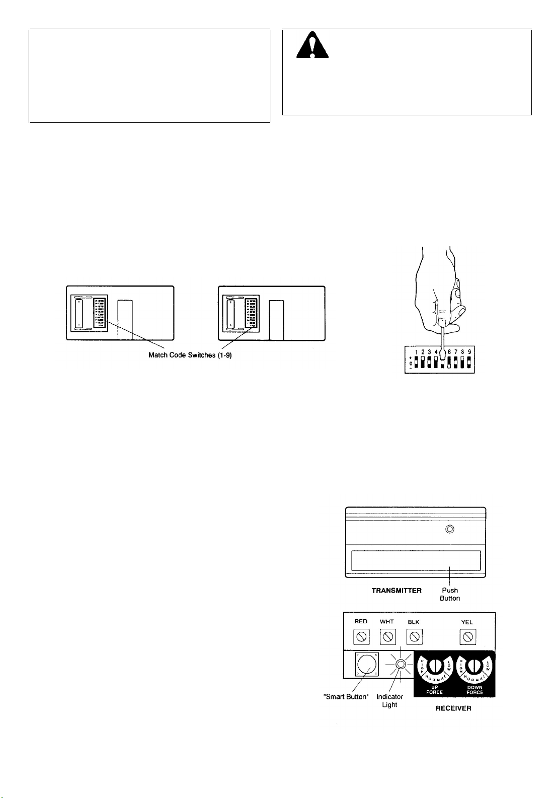
1. Slide battery compartment cover back to access code switches in your single function remote and any new remote
control.
2. Place remotes side by side as shown and set switches in ALL remotes to matching positions (+, -, 0). Use a pen or
screwdriver to slide the code switches.
NOTE: Instructions for matching the code switches in two-channel and multi-function remote control
transmitters are Included with those accessories.
MATCH/CHANGE THE CODE IN THE RECEIVER
GARAGE DOOR OPENERS
WITH RECEIVER "SMART" CODE BUTTON
3. Press the RECEIVER Smart Button on the back panel
of the opener as shown. The adjacent indicator light
will turn ON.
CAUTION: Door will begin to move Immediately If any
transmitter has been activated.
If this occurs, wait until the door has completed Its UP
or DOWN cycle. Then begin again at Step 3.
4. STAND AWAY FROM THE DOOR and press the
remote control transmitter push button. The indicator
light will turn OFF and the door will move. Receiver
and remote control(s) codes now match. The opener
will operate when either the door control button or the
remote control transmitter push button is pressed.
NOTE: If the remote control transmitter push button is
not pressed within 30 seconds, the indicator light will
turn OFF. In that case, begin again at steps 3.
23
Page 24
Having a Problem?
DOOR DOESN'T CLOSE
COMPLETELY
SITUATION PROBABLE CAUSE & SOLUTION
Review Pages 2 and 3 Before Proceeding
OPENER DOESN'T OPERATE
FROM EITHER THE DOOR
CONTROL BUTTON OR REMOTE
CONTROL TRANSMITTER
OPENER OPERATES FROM
REMOTE CONTROL BUT
NOT FROM DOOR CONTROL
BUTTON
DOOR OPERATES FROM
DOOR CONTROL PUSH BUTTON
BUT NOT FROM THE REMOTE
CONTROL TRANSMITTER
REMOTE CONTROL TRANSMITTER
HAS SHORT RANGE
1. Have you disengaged all door locks? Review Step 7, page 16.
2. Does the opener have electric power? Plug a lamp into the outlet. If it doesn't light, check fuse
box or circuit breaker. (Some outlets are controlled by a wall switch.)
3. Repeated operation may have tripped the overload protector in the motor. Wait 15 minutes. Try
again.
4. Is there a build-up of ice or snow under door? Door may be frozen to ground. Remove any
obstruction.
5. Remove bell wire from opener terminals. Short red and white terminals by touching both
terminals at same time with a piece of metal (screwdriver or coin). If opener runs, check for a
faulty wire connection at door control button or a short under staples.
1. Is door control push button lit? If not, refer to No. 5 above and follow same procedure.
2. Are wiring connections correct? Review Step 5, page 14 or 15.
1. Is the LOCK Switch ON? (Models 1160 and 1150) Turn it OFF.
2. Does the battery test light glow when remote control push button is pressed? If not, replace
the battery.
3. If you have two remote controls and only one operates, review the code setting procedures on
page 23. ALL remote controls must be set to same code.
1. Check battery test light. If the light is dim, change the battery.
2. Change the location of the remote control in the car.
3. A metal garage door or foil-backed insulation or metal siding will reduce the transmission
range.
4. Check to be sure antenna on the back panel of opener extends fully downward.
THE GARAGE DOOR OPENS
AND CLOSES BY ITSELF
DOOR DOESN'T OPEN
COMPLETELY
DOOR WON'T CLOSE
1. Is there a neighbor with a garage door opener using the same frequency code? Change your
code. Review page 23.
2. Check to be sure that the remote control push button is not stuck in the 'down' position.
3. Remove bell wire from opener terminals and operate from remote control only. If this solves
the problem, the door control is faulty (replace), or there is a short or broken wire between door
control button and opener.
1. Is something obstructing the door?
2. If door opens at least 5 feet, travel limits may need to be increased. One turn equals 2 inches
of travel. See page 20.
REPEAT SAFETY REVERSE TEST after the adjustment is complete.
3. If door has been working properly but now doesn't open all the way, increase the UP FORCE
See page 21.
REPEAT SAFETY REVERSE TEST after the adjustment is complete.
1. Is something obstructing the door?
2. Review the Travel Limits Adjustment Chart on page 20.
REPEAT SAFETY REVERSE TEST after any adjustment of door arm length, close
force or down limit.
1. Check the Protector System (if you have installed this accessory). If the light is blinking,
correct alignment.
24
Page 25

Having a Problem? (continued)
CHAIN DROOPS OR SAGS
SITUATION PROBABLE CAUSE & SOLUTION
DOOR REVERSES FOR
NO APPARENT REASON
OPENER LIGHT(S)
OPENER STRAINS OR
MAXIMUM FORCE IS NEEDED
TO OPERATE DOOR
1. Pull red manual release handle. Operate door manually. If it is unbalanced or binding, call a
garage door serviceman to correct the problem.
2. Clear any ice or snow from garage floor area where garage door closes.
3. Review the Force Adjustment Chart on page 21. REPEAT SAFETY REVERSE
TEST after adjustment is complete.
4. If door reverses in FULLY CLOSED position, decrease travel limits (Page 20).
REPEAT SAFETY REVERSE TEST after the adjustment is complete. THE NEED FOR
OCCASIONAL ADJUSTMENT OF THE FORCE AND LIMIT SETTINGS IS NORMAL.
WEATHER CONDITIONS IN PARTICULAR CAN AFFECT DOOR TRAVEL.
5. Check the Protector System (if you have installed this accessory). If the light is blinking.
correct alignment.
DOESN'T TURN ON
1. Replace the light bulb (75 watts maximum). Use a "garage door opener bulb" if standard bulb
burns out prematurely due to vibration. Vibration may be caused by loose end panel. Retighten
screws.
DOESN'T TURN OFF
1. There may be a defective ground at ceiling or wall receptacle.
UNIT MUST BE GROUNDED.
2. Is the Light Feature ON ? Turn it OFF.
1. Door may be out of balance or springs are broken. Close door and use manual release rope
and handle to disconnect trolley. Open and close door manually. A properly balanced door will
stay in any point of travel while being supported entirely by its springs. If it does not, call a
garage door serviceman to correct the problem .
OPENER MOTOR HUMS
BRIEFLY, THEN WON'T WORK
OPENER WON'T OPERATE
DUE TO POWER FAILURE
OPENER NOISE IS DISTURBING
IN LIVING QUARTERS OF HOME
1. Garage door springs are broken. SEE ABOVE.
2. The trolley may be jammed into stop bolts. Pull or push on door while motor is humming to
release jammed condition. Re-adjust door limits (page 20) to prevent over-travel.
REPEAT SAFETY REVERSE TEST after adjustment is complete.
3. If the problem occurs on first operation of the opener, door is locked. DISABLE DOOR LOCK.
If chain was removed and reinstalled, motor may be out of phase. Remove chain; cycle motor
to the down position. Observe drive sprocket. When it turns in clockwise direction and stops in
down position, reinstall chain.
REPEAT SAFETY REVERSE TEST after adjustment is complete.
1. Use manual release rope and handle to disconnect trolley. Door can be opened and closed
manually. When the power is restored, press the door control button and trolley will
automatically reconnect.
2. The Outside Quick Release Lock accessory (for use on garages with no service door)
disconnects the trolley from outside the garage in case of power failure.
1. It is normal for chain to droop slightly in the closed door position. Use manual release rope and
handle to disconnect trolley. If chain returns to normal height when the trolley is disengaged
and door reverses on a one-inch obstruction, no adjustments are needed {see page 9).
1. If operational noise is a problem because of proximity of the opener to the living quarters,
Vibration Isolator Kit 41A3263 can be installed. This kit was designed to eliminate the
'sounding board effect' and is easy to install
25
Page 26
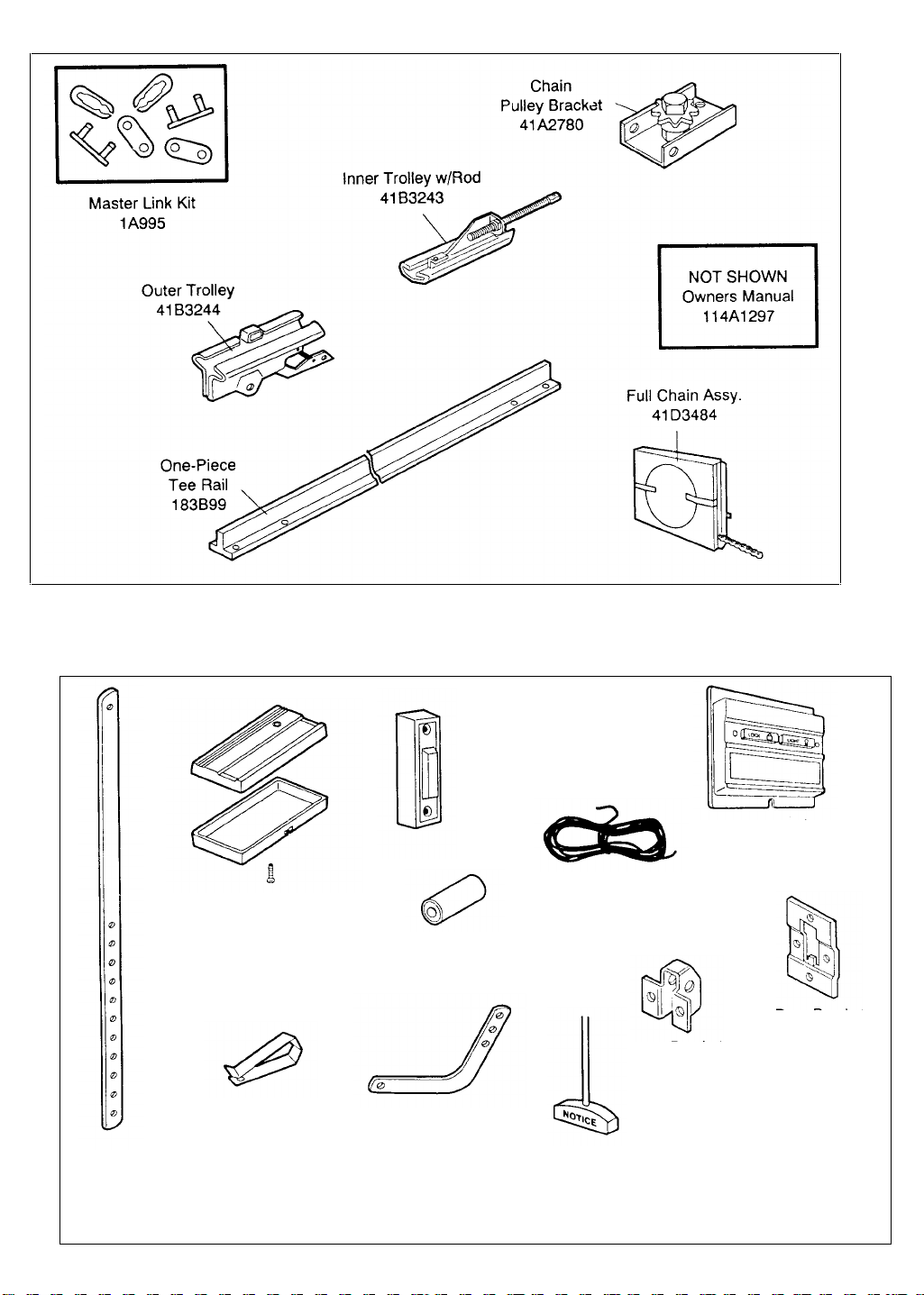
RAIL ASSEMBLY PARTS LIST
2 Strand 4 Strand
Bell Wire Bell Wire
217A238 217A241
6
17
4
1
3
2
7
5
INSTALLATION PARTS LIST
10
Lighted Push
Button Assembly
41 A2756
8
Straight Door
Arm Section
178B34
9
Remote Control Transmitter
Case, Cover & Screw Assembly
(circuit board not included)
41 A3593
11
Remote Control
Transmitter
Visor Clip
29C128
1
12
12V Battery
10A14
15
Curved Door
Arm Section
178B35
26
13
16
Manual Release
& Handle Assembly
41 A2828
Door Bracket
12B374
14
Multi-Function
Control Panel
41A3586
18
Door Bracket
Plate 12B380
19
Header Bracket Plus
Clevis and Fastener
41 A2829
Page 27
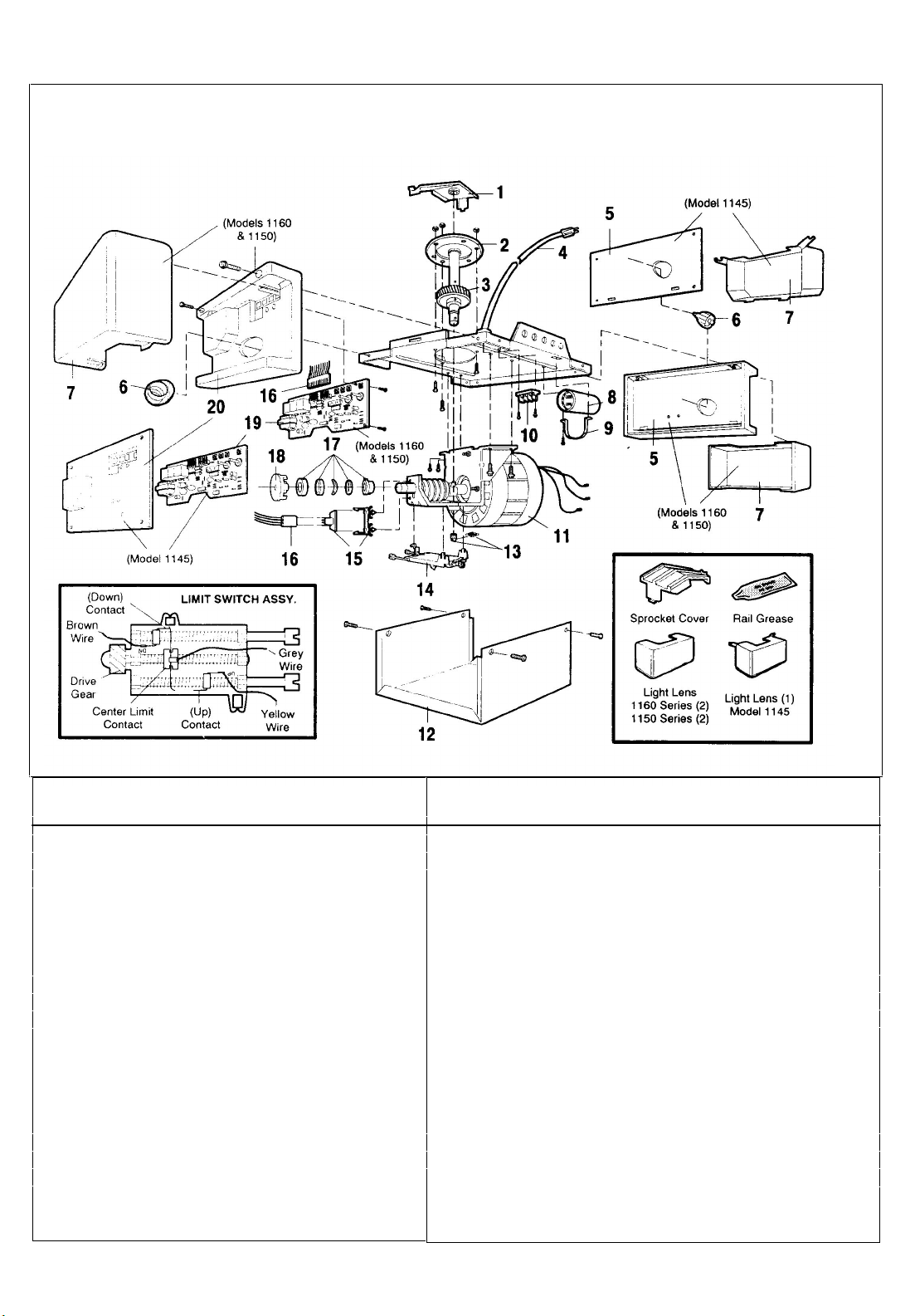
Repair Parts
Chassis Assembly Parts List
KEY PART
NO. NO. DESCRIPTION
1 31C290 Sprocket cover
2 41A2827 Gear and sprocket assy.
Complete with:
Spring washer
Thrust washer
Retaining ring
Bearing plate
Roll pins (2)
Drive gear
Worm gear
Helical gear w/retainer
Grease
3 41A2817 Drive/worm gear kit w/ grease
Roll pins (2)
4 41B2991-1 Line cord
5 143D100 End panel (Model 1145)
41A2916 End panel (Model 1160, 1150)
6 175B88 Light socket
7 108D36 Lens (Model 1145)
108D34 Lens (Models 1160, 1150)
8 30B363 Capacitor - 1/2HP
30B387 Capacitor - 1/3HP
9 12A373 Capacitor baracket
KEY PART
NO. NO. DESCRIPTION
10 41A3150 Terminal block w/screws
11 41D3058 Universal replacement motor
/bracket assy. (Includes
motor, worm, bracket, bearing
assy. and RPM sensor)
12 51R370 Cover (Specify model)
13 41A2818 Helical gear & retainer w/grease
14 41D3452 Limit switch assembly
15 41C3005 RPM sensor assembly
16 41C2726 Wire harness assy. w/plug
17 41A2826 Shaft bearing kit
18 41A2822 Interrupter cup assy.
19 41A3627 Receiver logic board assy. (Model 1145)
41A3626 (Models 1160 and 1150)
Complete with:
Logic board
End panel w/all labels
20 41A3712 End panel w/all labels (Model 1145)
41A3673 End panel w/all labels (1160 and 1150)
NOT SHOWN
41A2825 Chassis assy. hardware kit (includes
screws not designated by a number in
illustration)
27
Page 28

LIFT-MASTER SERVICE
• MODEL NUMBER
SERVICE INFORMATION
TOLL FREE NUMBER:
1-800-654-4736
HOW TO ORDER
IS ON CALL
OUR LARGE SERVICE Organization
SPANS THE UNITED STATES AND CANADA
INSTALLATION AND SERVICE INFORMATION IS AS
NEAR AS YOUR TELEPHONE SIX DAYS A WEEK.
SIMPLY DIAL OUR TOLL FREE NUMBER:
1-800-654-4736
HOURS: 7:00 a.m. TO 3:30 p.m.
(Mountain Std. Time)
MONDAY through SATURDAY
For professional installation parts and service contact your
local LIFT-MASTER/CHAMBERLAIN dealer. Look for him in
the Yellow Pages or call our Service number for a list of
dealers in your area.
REPAIR PARTS
Selling prices will be furnished on request or parts will be
shipped at prevailing prices and you will be billed
WHEN ORDERING REPAIR PARTS ALWAYS GIVE THE
FOLLOWING INFORMATION:
• PART NUMBER
• PART NAME
ADDRESS ORDERS TO:
CHAMBERLAIN MFG.
Unit 11 230 Bayview Drive
Barrie Ont. Canada L4N 5E9
, CANADA INC.
LIFTMASTER GARAGE DOOR OPENER ONE-YEAR LIMITED WARRANTY
The Chamberlain/Lift-Master warrants to the first retail purchaser of this product that it will be free from any defect in materials and/or
workmanship for a period of twelve full months from the date of purchase. The product must be used in complete accordance with LiftMaster's instructions for installation. or operation and care.
LIMITED WARRANTY ON MOTOR
Model 1160: The motor is warranteed to be free from any defect in materials and/or workmanship for a period of 60 full months (5 years)
from the date of purchase.
Models 1150 and 1145: The motor is warranteed to be free from any defect in materials and/or workmanship for a period of 36 full months
(3 years) from the date of purchase.
This warranty does not cover non-defect damage caused by unreasonable use (including abuse failure to provide reasonable and
necessary maintenance or any alterations to the product), labor charges for dismantling or reinstalling of a repaired or replaced unit or
replacement batteries.
If duri ng the warranty period the product appears as though it may be defective CALL OUR TOLL FREE SERVICE NUMBER BEFORE
DISMANTLING IT (1-800-654-4736). If the product is then alleged to be defective please send it pre-paid and insured to our Service
Center to obtain warranty repair You will be advised of shipping instructions when you call the number listed above.
Please be sure to include a brief description of the problem and a dated proof-of-purchase receipt with any product that is returned for
warranty repair.
Product under warranty which upon receipt by Chamberlain/LiftMaster is determined to be defective in materials and/or workmanship will be
repaired or replaced (Chamberlain's option) at no cost to you and returned pre-paid. Defective parts will be repaired or replaced with new or
factory rebuilt parts at Chamberlain's option.
THE DURATION OF IMPLIED WARRANTIES OF MERCHANTABILITY AND FITNESS FOR A PARTICULAR PURPOSE IS
TO THE DURATION OF THIS WRITTEN WARRANTY. SOME PROVINCES MAY NOT ALLOW LIMITATIONS ON HOW LONG AN
IMPLIED
All claims for consequential or incidental damages for breach of this warranty are excluded and in no event shall manufacturer's liability for
breach of warranty negligence strict liability or breach of contract exceed the cost of the product covered herein but the purchaser is entitled
to the remedies expressly provided in this policy. Some provinces do not allow the exclusion or limitation of incidental or consequential
damages so the above limitation or exclusion may not apply to you.
No representative or person is authorized to assume for us any other liability in connection with the sale of this product. This warranty gives
you specific legal rights and you may also have other rights which may vary from province to province.
WARRANTY LASTS SO THE ABOVE LIMITATION MAY NOT APPLY TO YOU.
LIMITED
114A1297 Printed in Mexico
1990, Chamberlain Mfg. Canada
Inc. All rights reserved
 Loading...