

Page 1
AD35 G2 PIR Quad Element Manual
Challenger_AD35 _Instructions_Rev01
FIRES
WINDOW S BOILERS RADIATORS
PIR
B
B
B
C
C
AA
5
0
-5
-10
Sensor
AD35 G2 PIR Quad Element Features
Grade 2 four-element passive infra-red intrusion detector.
EXTRA Low (9 mA) current draw @12V DC operation.
S.M.D. Technology.
12m, 110∘Convex honey comb, hemispherical infra-red lens.
Walk test LED.
High RFI & EMI Immunity.
Pulse Counter (1, 2 and 4 pulses selectable)
Temperature compensation for the sensitivity of the PIR.
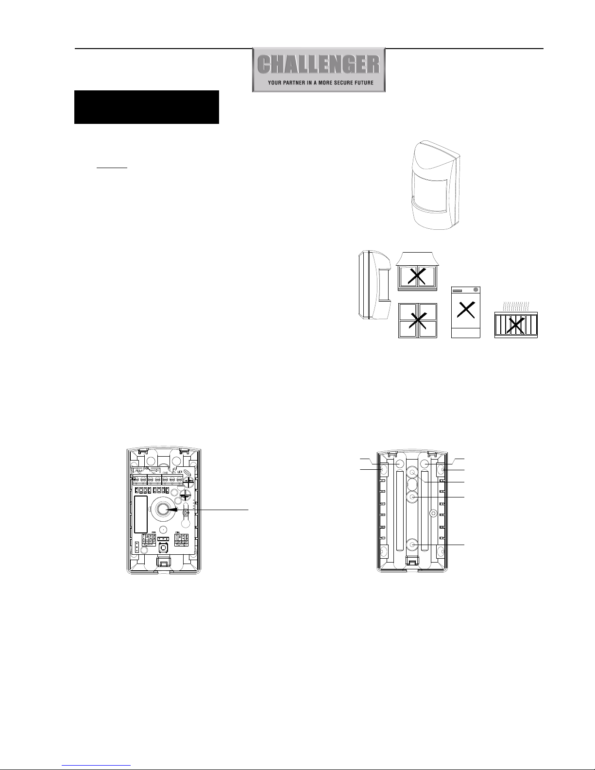
Mounting Location
The AD35 is designed for indoor use. It should not be mounted near to
large metal objects or on metal surfaces. It needs to be mounted on a
wall or in a corner at a height of approximately 2-2.5meters for the
best general coverage in an average room. The detector has been
designed to avoid false alarms, nevertheless, it is best to avoid looking
directly at sources of heat such as fires and boilers, and always try to
keep away from a window. A PIR can look at a radiator but should not
be sited above one.
Do not site a PIR where its field of view may be obstructed (e.g. by curtains). Also
note that PIRs work best when sensing movement across rather than along their detection beams. You need to consider the need
to wire these units back to the Control Unit.
Mounting the detector
1. Remove and retain the screw from the bottom of the PIR and lift off the cover.
2.
Carefully remove the electronic module from its retaining clips, ensuring not to touch the pyroelectric sensor
(Illustration 1).
Illustration 1
Illustration 2
3. Use mounting points “A”, if you are fitting the detector in a corner. Use mounting points “B”, if you are fitting the detector
on a flat surface. Use a small drill to create two fixing holes at the mounting points (Illustration 2).
4. Hold the base of the PIR in the chosen position, ensuring that the front of the PIR will face
towards the center of the protected area, mark and drill two fixing holes in the wall.
Choose one of the cable entry holes “C” and make a third hole in the detector base. Put one end of the wire through this
hole “C”, then secure the PIR to the wall.
5. Replace the electronic module into the retaining clips, ensuring that it is correctly positioned and firmly seated.
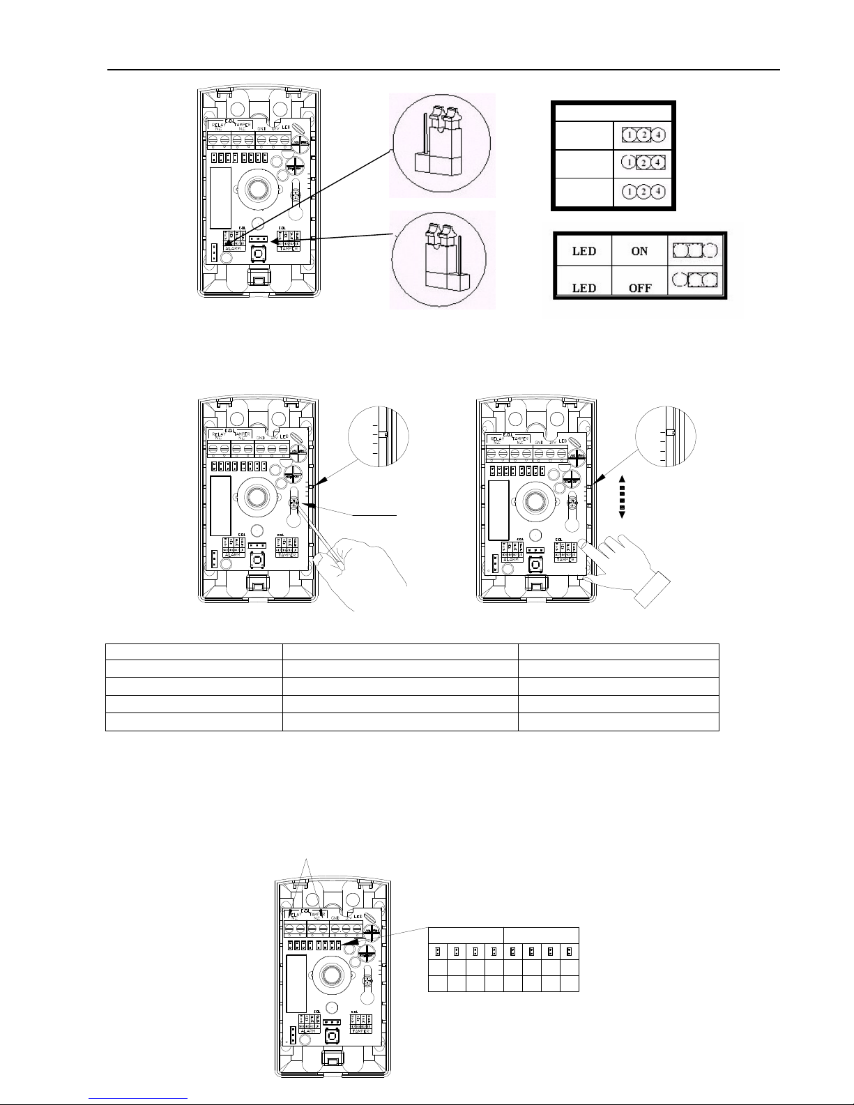
6. If required, select the PIR LED “ON” or “OFF” option and the sensitivity (pulse count) by setting the corresponding
jumpers on the electronic module. Note that Pulse 1 option is more sensitive than the pulse 4 option. Pulse 1 option is used
when it is necessary to activate an alarm on the first detected pulse, or in high security installations – where fast “catch”
performance is of greatest importance. Pulse 2 or 4 settings provides improved protection against false alarms caused by all
types of environmental disturbances. (Illustration 3)
MODEL NO. AD35
Page 2
AD35 G2 PIR Quad Element Manual
Challenger_AD35 _Instructions_Rev01
5
0
-5
-10
5
0
-5
-10
5
0
-5
-10
5
0
-5
-10
-10
-5
0
5
PCB Screw
Adjustment Scale Adjustment Scale
E.O.L
Black
Red Blue
YellowYellow
BlueRed
Black
1K
4K75K66K8
1K2K2
5K6
4K7
Tamper
Alarm
5
0
-5
-10
7. Position the PCB by loosening the PCB screw, and sliding the PCB up or down to the required setting (Illustration 4) . The
optimal coverage area is obtained if the PCB is on setting ‘0’ (default value).
Note : The distance range is 12m at ‘0’. An increase coverage angle will decrease the distance.
8. For disable EOL function do not set jumpers of alarm and tamper. (Illustration 6) Please Note: for Grade 2 EOL function is
required
9.
10. Selectable EOL resistance.
Refer to the chart below for the correct end of line resistance, and set jumpers of alarm and tamper.
(
Illustration 5、Illustration 7 and Illustration 8)
Vertical Adjustment Setting Distance range(m) Coverage Angle
+ 5 14
70∘
0 12
110∘
-5 9.0
110∘
-10 7.0
110∘
Pulse Count
Pulse 1
Pulse 2
Pulse 4
Illustration 3
Illustration 4
Page 3

AD35 G2 PIR Quad Element Manual
Challenger_AD35 _Instructions_Rev01
Control panel types available on this model.
Type Control Panel Alarm Tamper
1 Honeywell, Ademco Microtech 1K 1K
2
Challenger (Force-48),
Scantronic, Menvier,
Pyronix PCX (12, 22, 44, 128 VID), Texecom,
Castle CareTech G3 Plus.
4K7
2K2
3 DSC 5K6 5K6
4 Guardtec 6K8 4K7
5 Pyronix Matrix, PCX SMS, 134, 256. 4K7 4K7
Wiring Diagram
1). Use this wiring configuration when connecting normally closed 2).Fully Supervised (Force-48 illustrated)
detection devices to the zone using 6-Wires.
(Force-48 illustrated)
3). Use this wiring configuration when connecting normally closed detection devices to the zone using 6-Wires. (Force-10 illustrated)
Please Note: If more than one tamper is to be wired Force 10 system then the TAMP circuit will need to be wired in series and not parallel.
Tamper E.O.L resistor=N.P
Alarm E.O.L resistor=N.P
Illustration 5
Illustration 8
5
0
-5
-10
AUX
E.O.L
Zone
0V
+13V
A
T
C
Tamper E.O.L resistor=2K2
Alarm E.O.L resistor=4K7
Illustration 7 Illustration 6
5
0
-5
-10
C
T
A
+13V
0V
Zone
AUX
Tamper E.O.L resistor=N.P
Alarm E.O.L resistor=N.P
Page 4

AD35 G2 PIR Quad Element Manual
Challenger_AD35 _Instructions_Rev01
11. Connect the wires in accordance with the terminal block connections.
–
12V+ Connect to a regulated D.C. power source, observing correct polarity.
TAMP Connect to a Tamper or 24 Hr. zone, NC in the control panel. Note these are normally closed switch contacts
which open when the tamper opens.
ZONE Connect to an Alarm zone, NC in the control panel. Note these are normally closed relay contacts which
open when the detector alarms.
Walk Testing
A. Apply power and allow 3 minutes for warming up and stabilizing.
B. Adjust the vertical pattern angle per Fig.1 below.
C. Walk slowly across the field of view (in opposite directions) and observe the LED – it lights whenever you enter or exit a
sensitive beam. Allow 5 seconds between each test for the unit to stabilize.
D.
After testing, the LED can be disabled to prevent unauthorized tracing of the coverage pattern. To disable the LED,
remove the jumper from the left and middle pins of the LED selector (ON) and place it across the middle and right pins
(OFF).
Specifications
Operating Voltage 9 - 15V DC
Detector Dual Element low noise Pyroelectric sensor
Current Draw 9 mA nominal at 12 VDC
Alarm Output Normally closed dry contacts (0.5A/24V) with 15Ω resistor in series
Tamper Output Normally closed dry contacts (0.5A/24V)
Alarm Period 2-3 seconds
Pulse Count 3 position selector 1, 2 and 4 pulse operation
LED Walk test enabled and disabled with internal link
Coverage 110∘
Range Up to 12 meters at “0”
Operating Temperature 0 - 50℃
Due to our policy of continuous improvement we reserve the right to change specification without prior notice. Errors
and omissions accepted. These instructions have been carefully checked prior to publication. However, no
responsibility can be accepted by Challenger Security Products for any misinterpretation of these instructions.
Distributed by:
CHALLENGER SECURITY PRODUCTS
10 SANDERSONS WAY, BLACKPOOL, FY4 4NB
Email: enquiries.challenger@adivision.co.uk
Website: www.challenger.co.uk
 Loading...