

Page 1

AMD Socket A
NVIDIA nForce2 Ultra 400 + MCPS
ATX Motherboard
User's Guide
Version 1.0
Page 2

Declaration of Conformity
According to 47 CFR, Parts 2 and 15 of the FCC Rules
The following designated product:
EQUIPMENT: MAINBOARD
is a Class B digital device that complies with 47 CFR Parts 2 and 15 of the FCC Rules.
Operation is subject to the following two conditions:
1. This device may not cause harmful interference.
2. This device must accept any interference received, including interference that may
cause undesired operation.
This declaration is given to the manufacturer:
CHAINTECH-EXCEL COMPUTER INC.
4427 Enterprise St. Fremont, CA 94538, U.S.A.
http://www.chaintechusa.com
Chaintech President: Simon Ho
Signature:
Page 3

Federal Communications Commission Statement
This device complies with FCC Rules Part 15. Operation is subject to the following two
conditions:
* This device may not cause harmful interference.
* This device must accept any interference received, including interference that may cause undesired
operation.
This equipment has been tested and found to comply with the limits for a Class B digital device,
pursuant to Part 15 of the FCC Rules. These limits are designed to provide reasonable protection
against harmful interference in a residential installation. This equipment generates, uses, and can
radiate radio frequency energy. If this equipment is not installed and used in accordance with the
manufacturer's instructions, it may cause harmful interference to radio communications. However,
there is no guarantee that interference will not occur in a particular installation. If this equipment does
cause harmful interference to radio or television reception, which can be determined by turning the
equipment off and on, the user is encouraged to try to correct the interference by one or more of the
following measures:
* Reorient or relocate the receiving antenna.
* Increase the separation between the equipment and receiver.
* Connect the equipment to an outlet on a circuit different from that to which the receiver is
connected.
* Consult the dealer or an experienced radio/TV technician for help.
The use of shielded cables for connection of the monitor to the graphics card is required to assure
compliance with FCC regulations. Changes or modifications to this unit not expressly approved by
the party responsible for compliance could void the user's authority to operate this equipment.
Canadian Department of Communications Statement
This digital apparatus does not exceed the Class B limits for audio noise emissions from digital
apparatuses set out in the Radio Interference Regulations of the Canadian Department of
Communications.
Manufacturer's Disclaimer Statement
The information in this document is subject to change without notice and does not represent a
commitment on the part of the vendor. No warranty or representation, either expressed or im plied, is
made with respect to the quality, accuracy or fitness for any particular purpose of this document. The
manufacturer reserves the right to make changes to the content of this document and/or the products
associated with it at any time without obligation to notify any person or organization of such changes.
In no event will the manufacturer be liable for direct, indirect, special, incidental or consequential
damages arising out of the use or inability to use this product or documentation, even if advised of the
possibility of such damages. This document contains materials protected by copyright. All rights are
reserved. No part of this manual may be reproduced or transmitted in any form, by any means or for
any purpose without expressed written consent of its authors. Product names appearing in this
document are mentioned for identification purposes only. All trademarks, product names or brand
names appearing in this document are registered property of their r e spective owners.
100%
Printed in Taiwan.
Nov 2003
OST-CONSUMER
RECYCLED PAPER
Page 4

Contents
C H A P T E R 1 INTRODUCTION ........................................... 1
1-1 PRODUCT SPECIFICATIONS ............................................................................. 1
1-2 PACKAGE CONTENTS..................................................................................... 3
1-3 MOTHERBOARD LAYOUT ............................................................................... 4
CHAPTER 2 HARDWARE SETUP................................... 5
2-1 INSTALLING A CPU PROCESSOR IN SOCKET A................................................... 5
2-2 CPU JUMPER CONFIGURATION ....................................................................... 6
2-3 MAIN MEMORY CONFIGURATION.................................................................... 9
2-4 CONNECTOR AND JUMPER REFERENCE CHART ................................................ 10
2-5 CONNECTOR AND JUMPER SETTINGS.............................................................. 11
CHAPTER 3 BIOS SETUP PROGRAM...................... 21
3-1 STANDARD CMOS SETUP............................................................................ 22
Date/Time................................................................................................... 22
IDE (Primary/Secondary; Master/Slave)........................................................ 22
Drive A/B ................................................................................................... 22
Video ......................................................................................................... 22
Halt On...................................................................................................... 22
3-2 ADVANCED BIOS FEATURES........................................................................ 23
CPU Internal Cache/External Cache............................................................. 23
Quick Power On Self Test (POST)................................................................. 23
First/Second/Third/Boot Other Device........................................................... 23
Swap Floppy Drive...................................................................................... 23
Boot Up Floppy Seek................................................................................... 23
Boot Up NumLock Status ............................................................................. 23
Gate A20 Option ......................................................................................... 23
Keyboard Interface:..................................................................................... 23
Security Option........................................................................................... 24
APIC Mode................................................................................................. 24
MPS Version Control OS ............................................................................. 24
OS Select For DRAM > 64MB...................................................................... 24
Show POST CODE...................................................................................... 24
Small Logo (EPA) Show............................................................................... 24
3-3 ADVANCED CHIPSET FEATURES .................................................................... 24
AGP Aperture Size (MB).............................................................................. 24
AGP Frequency........................................................................................... 25
AGP 8X Support.......................................................................................... 25
AGP Fast Write Capability........................................................................... 25
System BIOS Cacheable............................................................................... 25
Page 5

Contents
Video RAM Cacheable .................................................................................25
Flash BIOS Protection .................................................................................25
3-4 INTEGRATED PERIPHERALS ...........................................................................25
IDE Function Setup: ....................................................................................25
Onboard Device:.........................................................................................26
2. OnChip USB............................................................................................26
3. USB Keyboard/storage Support.................................................................26
Super IO Device:.........................................................................................27
3-5 POWER MANAGEMENT SETUP .............................................................27
ACPI Suspend Type .....................................................................................28
Power Management .....................................................................................28
Video Off Method ........................................................................................28
HDD Power Down.......................................................................................28
HDD Down In Suspend ................................................................................28
Soft-Off by PBTN.........................................................................................28
PWRON After PWR-Fail ..............................................................................29
Wake up Events...........................................................................................29
3-6 PNP/PCI CONFIGURATIONS ...............................................................29
Reset Configuration Data.............................................................................29
Resources Controlled By ..............................................................................30
PCI/VGA Palette Snoop ...............................................................................30
FDD IRQ Can Be Free.................................................................................30
3-7 FREQUENCY/VOLTAGE CONTROL.......................................................30
System Performance.....................................................................................30
FSB Frequency............................................................................................30
CPU Interface.............................................................................................30
Memory Frequency......................................................................................31
Memory Timing...........................................................................................31
3-8 LOAD FAIL-SAFE DEFAULTS .........................................................................32
3-9 LOAD OPTIMIZED DEFAULTS.........................................................................32
3-10 SUPERVISOR PASSWORD & USER PASSWORD SETTING....................................32
3-11 SAVE AND EXIT SETUP ...............................................................................32
3-12 EXIT WITHOUT SAVING..............................................................................32
CHAPTER 4 DRIVER SETUP.............................................33
4-1 NVIDIA DRIVER PACKAGE SETUP...................................................................33
4-2 C-MEDIA AUDIO DRIVER SETUP .................................................................33
4-3 LAN DRIVER SETUP....................................................................................33
4-4 USB 2.0 DRIVER SETUP...............................................................................33
4-5 DIRECTX SETUP .........................................................................................34
CHAPTER 5 C-MEDIA 3D AUDIO
Page 6

Contents
CONFIGURATION......................................................................... 34
5-1 SPEAKER OUTPUT....................................................................................... 34
5-2 S/PDIF ..................................................................................................... 34
5-3 VOLUME CONTROL ..................................................................................... 34
5-4 MICROPHONE............................................................................................. 35
5-5 XEAR 3D................................................................................................... 35
HOW TO CONTACT CHAINTECH................................................................ 36
Page 7

C h a p t e r 1 Introduction
1-1 Product Specifications Processor
- Supports AMD Socket-A Duron/Athlon XP CPU
- System clock supports 200/266/333/400MHz
Chipset
- NVIDIA nForce2 Ultra 400 + MCPS
Main Memory
- Three 184 pin DDR DIMMs up to 3GB
- Supports Dual-Channel DDR266/333/400 SDRAM modules
Expansion Slots
- One AGP slot for 4X/8X AGP
- Five 32-Bit PCI slots (v2.2 compliant)
5.1-Channel Audio
- With external high quality 5.1-Channel AC'97 Codec
- Complete software driver supports for Windows OS
- Optional S/PDIF out function
IDE
- Build-in nForce2 MCPS supports 2 UltraDMA-33/66/100/133 IDE ports
SATA RAID
- Build-in nForce2 MCPS supports 2 Serial ATA devices for the highest data transfer
rates (1.5Gbps burst) with RAID 0/1 solution
FDD
- One FDD connector supports up to 2.88MB
USB 2.0
- Build-in nForce2 MCPS supports total 8 USB 2.0/1.1 ports
- Supports USB 2.0 High-Speed Device @480 Mb/s Transfer Rates
Fast Ethernet
- On-board LAN chip RTL8101L supports 10/100Mb Fast Ethernet
Boot-Block Flash ROM
- Award system BIOS support PnP, APM, DMI, ACPI, & Multi-device booting features
Rear Panel I/O ports
- One PS/2 Mouse and Keyboard port
- Two USB ports and one RJ45 connector
- Two 9-pin D-Sub male Serial ports
1
Page 8

Chapter 1
- One 25-pin D-Sub female Parallel port
- Three Audio I/O jacks (Line-in, Line-out and Mic-in)
- One 15-pin D-SUB female Game/MIDI port
Internal I/O connectors
- Three 3x1 pin fan connectors
- Three 5x2 pin USB connectors for additional 6 USB ports
- Optional 3x2 pin SPDIF connector for additional SPDIF-out adaptor
- 3x1 pin wake on LAN connector with housing
- 3x1 pin wake on Modem connector with housing
- Two 4x1 pin CD-in connectors
- 9x2 pin front panel connector
- 5x2 pin front side audio connector
- 20 pin ATX Power connector
Form Factor
- ATX Form Factor 305mm x 210mm
2
Page 9

1-2 Package Contents
This product comes with the following components:
1. Motherboard x 1
2. 40-Pin UDMA-100 IDE Cable x 1
3. 34-Pin floppy Disk Drive Cable x 1
4. User’s Guide x 1
5. Driver CD x 1
Chapter 3
3
Page 10
Chapter 1
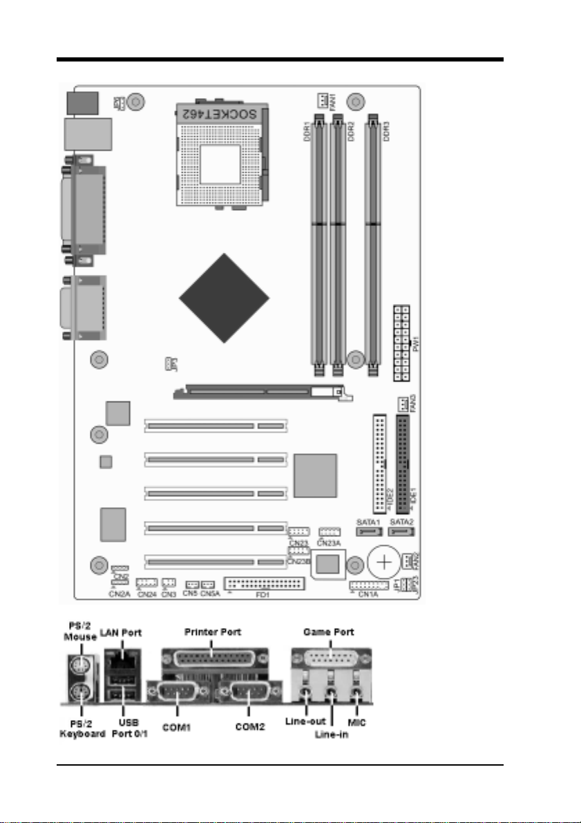
1-3 Motherboard Layout
4
Page 11
C h a p t e r 2 Hardware Setup
If your motherboard has already been installed in your computer you may still need to
refer to this chapter if you plan to upgrade your system's hardware.
This motherboard is electrostatic sensitive. Do not touch without wearing proper safety
gadget and make sure to disconnect the power cable from the power source before
performing any work on your motherboard. Not doing so may result in electrical shock!
2-1 Installing a CPU Processor in Socket A
The Socket A, designed for AMD Duron/Athlon/Athlon XP processors, has been
incorporated as a standard motherboard specification. To insert your CPU into Socket A
please do the following:
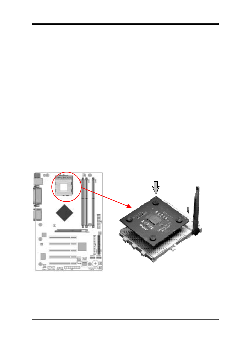
1. Locate a cut edge on the top surface of the CPU, which is close to one of the CPU
corners. The same corner will also be cut off, leaving a noticeable notch in the CPU's
corner. These markings indicate Pin 1 on the CPU.
2. Pull up the lever of Socket A so that it is perpendicular with the surface of the
motherboard. Gently insert the CPU with Pin 1 at the same corner of Socket A, which is
located close to the end of the lever. Allow the weight of the CPU to push itself into place.
Do not apply extra pressure as doing so may result in damaging your CPU. Snap the lever
back into place.
Installing an AMD approved heat sink with cooling fan is necessary for proper heat
dissipation from your CPU. Failing to install these items may result in overheating and
possible burnout of your CPU.
Notes: In order to boot up with a newly installed CPU, AC Power must be switched off
before installation.
5
Page 12

2-2 CPU Jumper Configuration Frequency Configuration
If you install a CPU on this motherboard, you must set the [CPU External Clock] JP3
according to your processor (See Section 3.3).
* CPU Speed = Multiplier x FSB Frequency
You do not need to make voltage settings because this board will automatically set your
CPU voltage.
AMD (K7) Duron CPU
Model CPU Speed FSB Multiplier
600 600 MHz 100 6.0 1.6V 64KB 0.18
650 650 MHz 100 6.5 1.6V 64KB 0.18
700 700 MHz 100 7.0 1.6V 64KB 0.18
750 750 MHz 100 7.5 1.6V 64KB 0.18
800 800 MHz 100 8.0 1.6V 64KB 0.18
Core
Voltage
L2
Cache
Manufacturing
Process
850 850 MHz 100 8.5 1.6V 64KB 0.18
900 900 MHz 100 9.0 1.6V 64KB 0.18
950 950 MHz 100 9.5 1.6V 64KB 0.18
1.0G 1.0 GHz 100 10.0 1.6V 64KB 0.18
1.1G 1.1 GHz 100 11.0 1.6V 64KB 0.18
1.2G 1.2 GHz 100 12.0 1.6V 64KB 0.18
1.3G 1.3 GHz 100 13.0 1.6V 64KB 0.18
6
Page 13

AMD Athlon CPU (K7/Thunderbird)
Model
700 700MHz 100 7.0 1.70V 256KB 0.18
750 750MHz 100 7.5 1.70V 256KB 0.18
800 800MHz 100 8.0 1.70V 256KB 0.18
850 850MHz 100 8.5 1.70V 256KB 0.18
900 900MHz 100 9.0 1.75V 256KB 0.18
950 950MHz 100 9.5 1.75V 256KB 0.18
CPU
Speed
FSB Multiplier
Core
Voltage
L2
Cache
Manufacturing
Process
1000
1100
1200
1300
1400
1000
1113
1200
1333
1400
000MHz 100 10.0 1.75V 256KB 0.18
100MHz 100 11.0 1.75V 256KB 0.18
200MHz 100 12.0 1.75V 256KB 0.18
300MHz 100 13.0 1.75V 256KB 0.18
400MHz 100 14.0 1.75V 256KB 0.18
000MHz 133 7.5 1.75V 256KB 0.18
113MHz 133 8.5 1.75V 256KB 0.18
200MHz 133 9.0 1.75V 256KB 0.18
333MHz 133 10.0 1.75V 256KB 0.18
400MHz 133 10.5 1.75V 256KB 0.18
7
Page 14

AMD Athlon XP CPU (Palomino/Thoroughbred)
Model
1500+ 1333MHz 133 10.0 1.7V 256KB 0.18
1600+ 1400MHz 133 10.5 1.7V 256KB 0.18
1700+ 1466MHz 133 11.0 1.7/1.6V 256KB 0.18/0.13
1800+ 1533MHz 133 11.5 1.7/1.6V 256KB 0.18/0.13
1900+ 1600MHz 133 12.0 1.7/1.6V 256KB 0.18/0.13
2000+ 1666MHz 133 12.5 1.7/1.6V 256KB 0.18/0.13
2100+ 1733MHz 133 13.0 1.7/1.6V 256KB 0.18/0.13
2200+ 1800MHz 133 13.5 1.65V 256KB 0.13
2400+ 2000MHz 133 15.0 1.65V 256KB 0.13
2600+ 2133MHz 133 16.0 1.65V 256KB 0.13
2600+ 2075MHz 166 12.5 1.65V 256KB 0.13
CPU
Speed
FSB Multiplier
Core
Voltage
L2
Cache
Manufacturing
process
2700+ 2167MHz 166 13.0 1.65V 256KB 0.13
AMD Athlon XP CPU (Barton)
2500+ 1833MHz 166 11.0 1.65V 512KB 0.13
2600+ 1917MHz 166 11.5 1.65V 512KB 0.13
2800+ 2075MHz 166 12.5 1.65V 512KB 0.13
3000+ 2167MHz 166 13.0 1.65V 512KB 0.13
3000+ 2100MHz 200 10.5 1.65V 512KB 0.13
3200+ 2200MHz 200 11.0 1.65V 512KB 0.13
8
Page 15
2-3 Main Memory Configuration
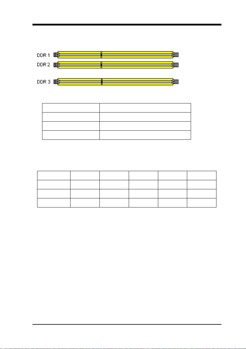
The DDR SDRAM memory system consists of three banks, each of which supports up to
1GB of memory.
DDR SDRAM Specifications
Memory Frequency Internal System BUS Frequency
133 MHz 266 MHz
166 MHz 333 MHz
200 MHz 400 MHz
DIMM type: 2.5V, unbuffered 184 pin 64/128/256/512-bit DDR SDRAM
Module size: Single/double-sided 64/128/256/512MB/1GB
Parity: Either parity or non-parity
Location 64 MB 128 MB 256 MB 512 MB 1.0 GB
DDR 1 V V V V V
DDR 2 V V V V V
DDR 3 V V V V V
Note:
For maximized Dual-channel (128-bit) result, you must install one of your two memory
modules on DDR3.
9
Page 16

2-4 Connector and Jumper Reference Chart
Jump Connector Function Page
PW1 ATX Power Supply Connector 10
CN1A Front Panel (Power / Rest / SPK…etc.) Connector 11
FD1 Floppy Connector 12
IDE1 / 2 IDE Hard-Disk Connector 13
JP1 CMOS Clear Jumper 13
JP3 CPU Bus Frequency Jumper 14
CN2 / 2A CD Audio-in Connector 14
JP6 Disable/Enable USB 0/1 Device Power ON Jumper 15
CN23/ 23A/CN23B CBOX™2 Front USB Connector 15
CN24 CBOX™2 Front Audio Connector 16
FAN1 / 2 / 3 CPU/ System / Case FAN Connector (12V) 16
CN5 / 5A Wake on LAN / Modem Connector 17
JP23 Green LED Mode Jumper 18
CN13 SPDIF OUT 19
SATA1/2 Serial ATA 19
10
Page 17
2-5 Connector and Jumper Settings
Connectors are used to link the system board with other parts of the system, including the
power supply, the keyboard, and the various controllers on the front panel of the system
case.
The power supply connector is the last connection to be made while installing a
motherboard. Before connecting the power supply, please make sure it is not connected
to the power source.
Note: All cables are security-proof.
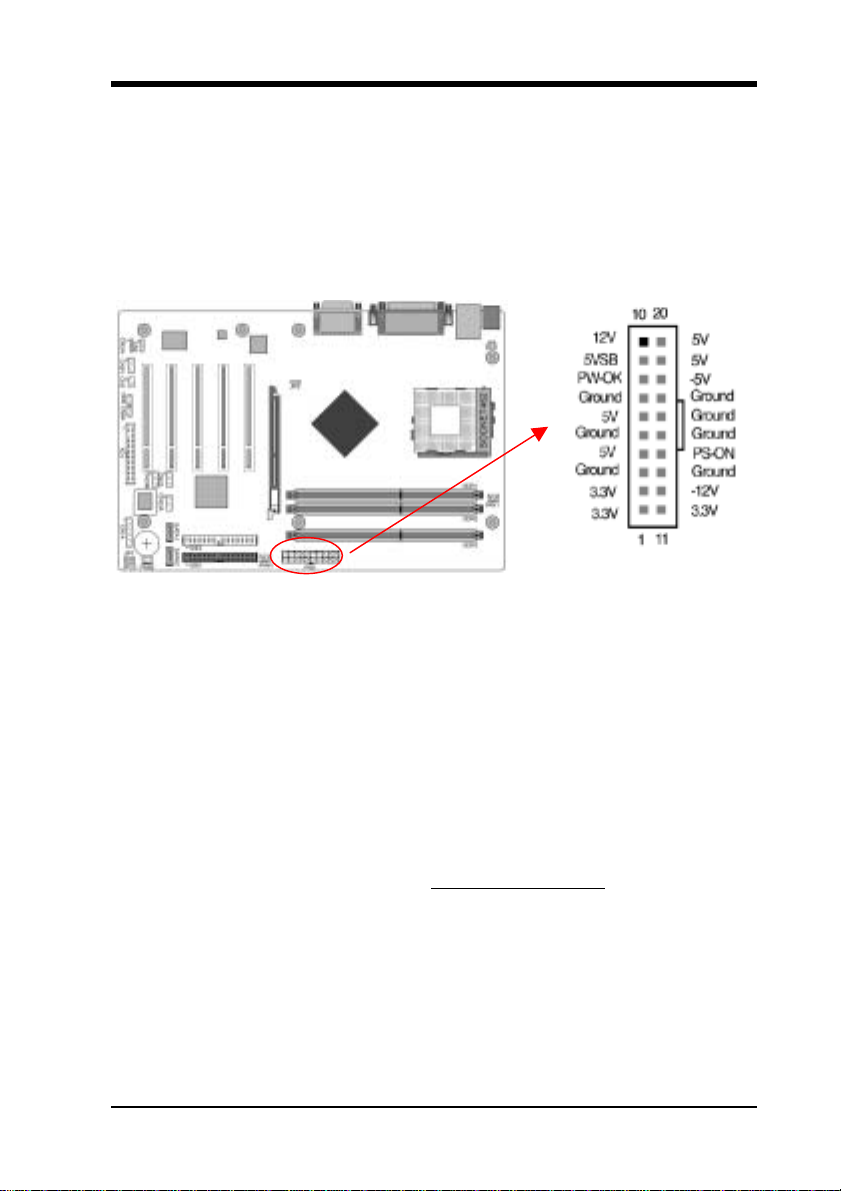
PW1 (ATX Power Supply Connector)
The power cord leading from the system's power supply to the external power source
must be the very last part connected when assembling a system. The ATX power supply
provides a single 20-pin connector interface, which incorporates standard +/-5V, +/-12V,
optional 3.3V and soft-power signals. The soft power signal, a 5V trickle supply is
continuously supplied when AC power is available. When the system is in the Soft-Off
mode, this trickle supply maintains the system in its minimum power state.
Power-On By Modem
While in Soft-Off state, if an external modem ring-up signal occurs, the system wakes up
and can be remotely accessed. You may enable this function in BIOS's Power
Management Setup menu. (See section 3.5)
Blinking LED in Suspend Mode
While in Suspend mode, the LED light on the front panel of your computer will flash.
Suspend mode is entered by pressing the Override Power Button
button on your ATX case, or enabling the Power Management and Suspend Mode options
in BIOS's Power Management menu. (See section 3.5)
Poly-fuse Over Current Protection
The poly-fuse protects the system from dangerous voltages that the system might be
exposed to via the keyboard or USB connector. In case of such exposure, the poly-fuse
will immediately be disconnected from the circuit, just like a normal fuse. After being
disconnected for a certain period of time, the poly-fuse will return to its normal state.
Then the keyboard or USB connector can function properly again. Unlike conventional
fuses, the poly-fuse does not have to be replaced, relieving the user wasted time and
, pushing the Green
11
Page 18
inconvenience.
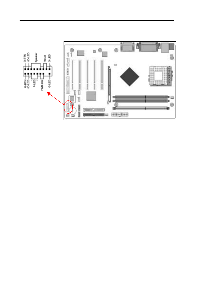
CN1A (Front Panel Connector) A through F
A. PWR-SW (Over-ride Power Button Connector)
The power button on the ATX chassis can be used as a normal power switch as well as
a device to activate Advanced Power Management Suspend mode. This mode is used
for saving electricity when the computer is not in use for long periods of time. The
Soft-OFF by PWR-BTN function in BIOS's Power Management Setup menu must be
set to [Delay 4 Sec.] to activate this function.
When the Soft-OFF by PWR-BTN function is enabled, pushing the power button
rapidly will switch the system to Suspend mode. Any occurrence of external activities
such as pressing a key on the keyboard or moving the mouse will bring the system back
to Full-On. Pushing the button while in Full-On mode for more than [4 seconds] will
switch the system completely off. See Over-ride Power Button Operation diagram.
B. P-LED (Power LED Connector)
The power indicator LED shows the system's power status. It is important to pay
attention to the correct cables and pin orientation (i.e., not to reverse the order of these
two connectors.)
C. G-BTN/G-LED (Green Button Switch/LED Connector)
Some ATX cases provide a Green button switch, which is used to put the system in
Suspend mode. In Suspend mode, the power supply to the system is reduced to a
trickle, the CPU clock is stopped, and the CPU core is in its minimum power state. The
system is woken up whenever the keyboard or mouse is touched. The system resumes
in different ways as defined by Power Management Setup screen in BIOS.
D. RESET (System Reset Switch Connector)
This connector should be connected to the reset switch on the front panel of the system
case. The reset switch allows you to restart the system without turning the power off.
12
Page 19
E. SPEAKER (Speaker Connector)
This 4-pin connector connects to the case-mounted speaker
F. HD-LED (IDE Activity LED Connector)
The IDE activity LED lights up whenever the system reads/writes to the IDE devices.
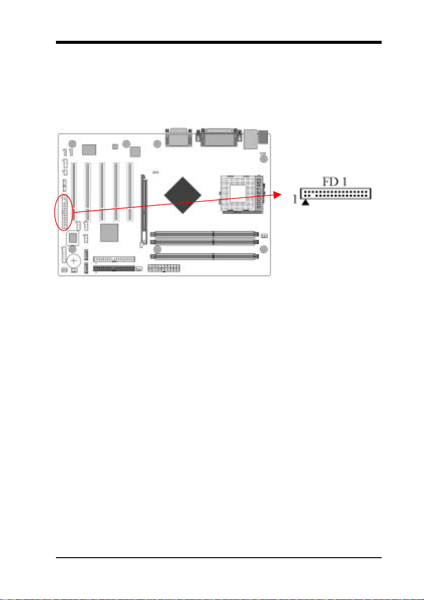
FD1 (Floppy Disk Connector)
This connector is used to connect 34 pins of Floppy.
13
Page 20
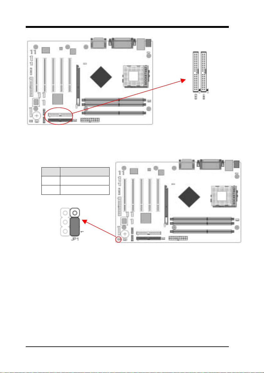
IDE 1/2 (IDE Hard-Disk Connector)
This connector is used for connecting 40 pins of ATAPI devices.
IDE 1 only connects two IDE devices. (Primary Master/Slave)
IDE 2 only connects two IDE devices. (Secondary Master/Slave)
JP1 (Clear CMOS Data)
Pin Definition
1-2 Normal (default)
2-3 Clear CMOS Data
To clear the contents of the CMOS, please follow the steps below.
1. Disconnect the system power supply from the power source.
2. Set the jumper cap at location [2-3] for <5 seconds>, and then set it back to the
default position.
3. Connect the system's power and then start the system.
4. Enter BIOS's CMOS Setup Utility and choose Load Setup Defaults. Type [Y] and
press [enter].
5. Set the system configuration in the Standard CMOS Setup menu.
14
Page 21
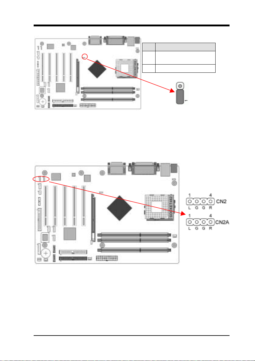
JP3 (CPU Bus Frequency)
Pin Definition
133/166/200 MHz
1-2
(default)
2-3 100 MHz
This cap setups up the CPU Ext. Clock Frequency.
1-2: The default value is 133/166 MHz (The will allow the CPU’s Ext. Frequency and
memory frequency to be adjusted through the BIOS.).
2-3: Set 100 MHz at CPU Ext. frequency. (The will allow the Memory frequency to be
adjusted through the BIOS.)
CN2/CN2A (CD-ROM Audio-in Connector)
Use the audio cable enclosed with your CD-ROM disk drive to connect the CD-ROM to
your motherboard. This will enable your CD-ROM's audio function.
15
Page 22
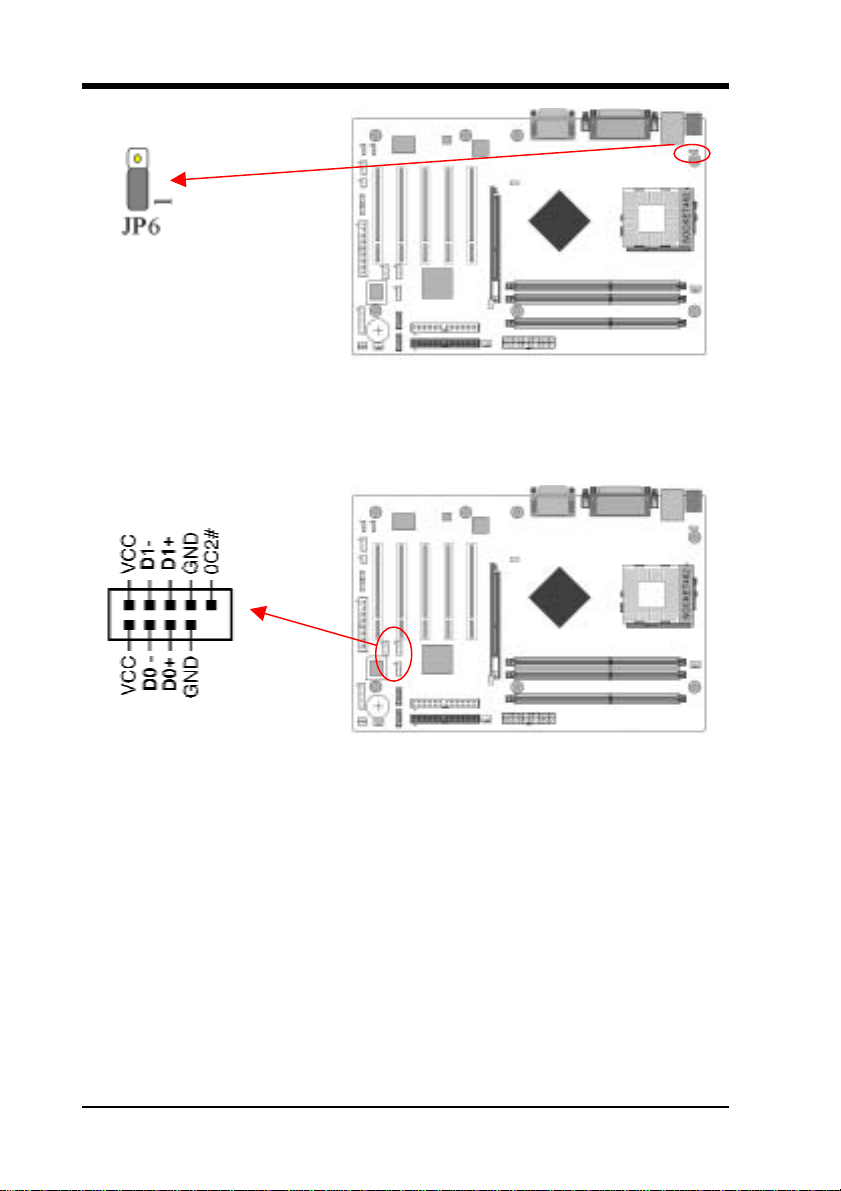
JP6 (Power On By USB 0/1)
A USB keyboard hot key or a USB mouse click can turn on this board. You must also
set this jumper's cap to pins 2-3 to use this function.
CN23/CN23A/CN23B (USB 2/3, 4/5 and 6/7 Connectors)
USB Port 2/3 Æ CN23, USB Port 4/5 Æ CN23A, USB Port 6/7 Æ CN23B
If you want to use a USB Keyboard, you must enable the USB keyboard support function
in BIOS's Integrated Peripherals menu (See Section 3.4). This board contains a USB Host
controller and includes a root hub with two connectors for optional USB Adaptor (USB
2/3 and 4/5).
16
Page 23
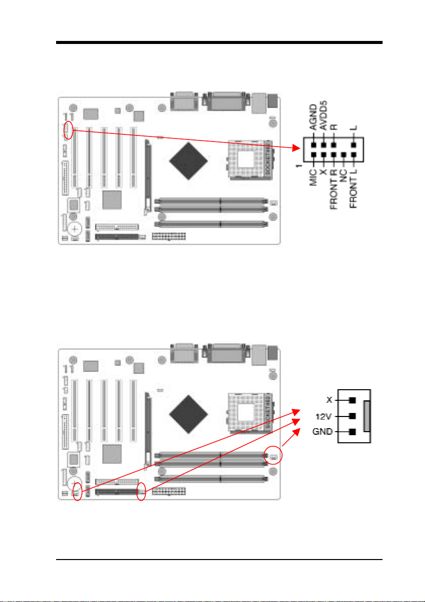
CN24 (Front Panel Audio Connector)
This connector give you the option of a front panel audio jack cable ext. to be plug into a
special custom designed system case.
Simply remove the two jumper caps at pin [5-6] and [9-10] then plug it into the (optional)
cable ext. connector. Pin [5-6] and [9-10] are shorted (default) to enable the back panel
audio function.
FAN1/FAN2/FAN3 (CPU/System/Case Cooling Fan Connectors)
The wiring and plug may vary depending on the manufacturer. On standard fans, the red
17
Page 24
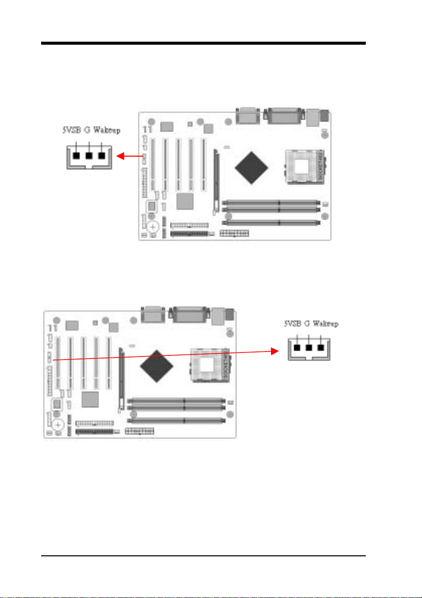
is positive (+12V), and the black is ground.
CN5 [WOL (Wake-on-LAN) Connector]
Enable the Power On by Ring/WOL selection in BIOS's Power Management Menu to use
this function. This header is used to connect an add-in NIC (Network Interface Card)
which gives WOL capability to the motherboard.
CN5A [WOM (Wake-on-Modem) Connector]
Enable the Power On by Ring/WOL selection in BIOS's Power Management Menu to use
this function. This header is used to connect an add-in modem card which gives WOM
capability to the motherboard.
18
Page 25
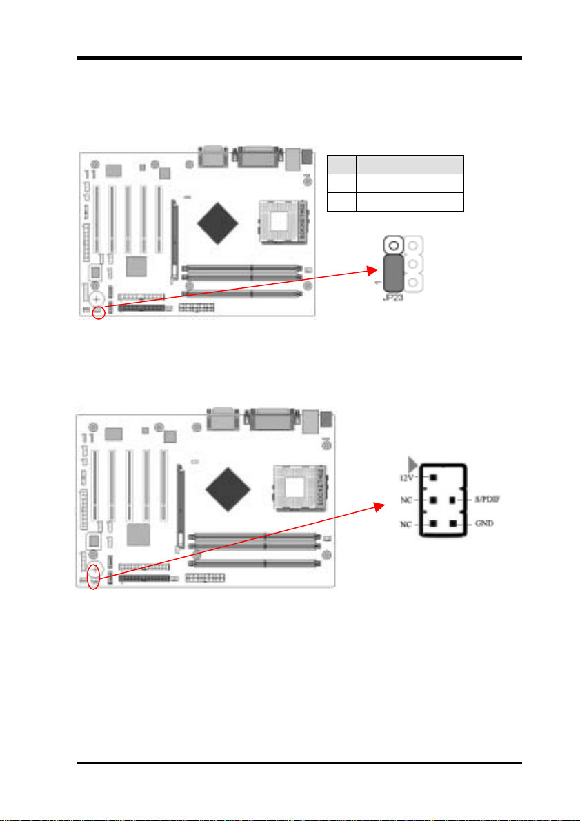
JP23 (Green Mode LED)
Pin Definition
1-2 Default
2-3 OEM
This cap is to setup Green LED flash mode.
CN13 (SPDIF OUT Connector)
To enable the S/PDIF function this connector must be connected to a S/PDIF bracket.
19
Page 26
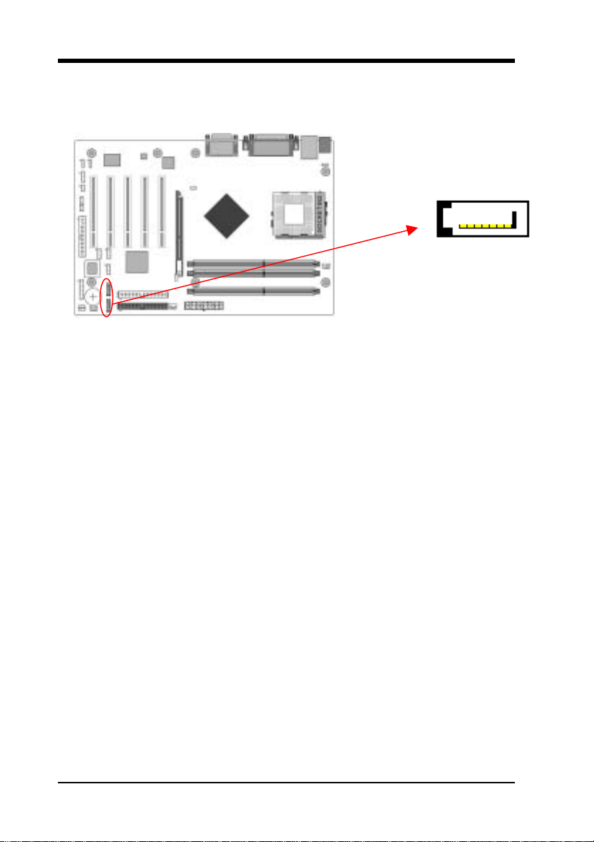
SATA1/2 (Serial ATA Connector)
This can connect to new IDE device; it supports ATA 150MB/sec.
Please refer to Section 2-6 Serial ATA and Parallel ATA for details.
20
Page 27
C h a p t e r 3 BIOS Setup Program
Phoenix-Award BIOS ROM has a built-in setup program that allows users to modify the
basic system configuration. This information is stored in CMOS RAM so that it can
retain the setup information, even when the power is turned off.
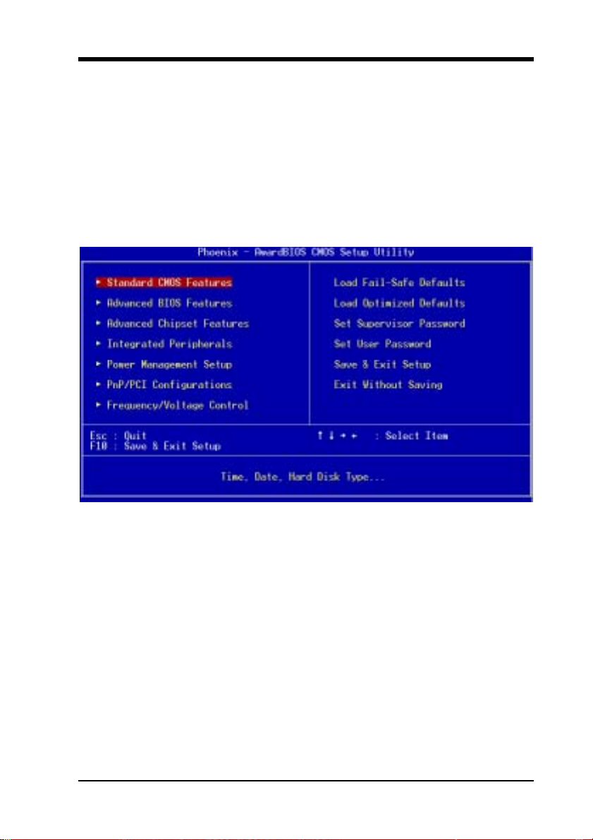
To enter the Phoenix-Award BIOS setup program press the [Delete] key when you
Power on or reboot the computer system. The primary screen as shown in Figure 3-1 is a
list of the menus and functions available in the setup program. Select the desired item by
your arrow keys and press enter to make the changes. Operating commands are located at
the bottom of this and all other BIOS screens. When a field is highlighted, on-line help
information is displayed on the right side of the screen.
Figure 3-1
21
Page 28

3-1 Standard CMOS Setup
The Standard CMOS Setup allows users to configure system components such as hard
disk drive, floppy disk drive and video display as well as date, time and boot-up error
signaling. This configuration menu should be changed when installing a motherboard for
the first time, changing hardware in your system such as the HDD, FDD, video display, or
when the CMOS data has been lost or contaminated. Choose the Standard CMOS Setup
option from the CMOS Setup Utility menu (Figure 3-1) to display the following screen.
Date/Time
Set the date and time of the system.
IDE (Primary/Secondary; Master/Slave)
This category identifies up to four IDE hard disk drives that have been installed in the
computer. This section does not show information on other IDE devices such as
CD-ROM drives or other hard drive type such as SCSI drives.
Drive A/B
Select different Floppy device Model. Available options are [None], [360K, 5-1/4 in],
[1.2M, 5-1/4 in], [720k, 3-1/2 in], [1.44M, 3-1/2 in], and [2.88M, 3-1/2 in].
Video
Select the type of video adapter present in your system. You can ignore this setting if you
are using a VGA monitor since VGA BIOS automatically configures this setting.
Halt On
When the system is powered on, BIOS performs a series of diagnostic tests called POST
(Power On Self Test). This function stops the computer if BIOS detects a hardware error.
You can tell BIOS to halt on all errors, no errors, or not to halt on specific errors.
22
Page 29

3-2 Advanced BIOS Features
By choosing the Advanced BIOS Features option from the CMOS Setup Utility menu
(Figure 3-1), the screen below is displayed. This sample screen contains the
manufacturer's default values for the motherboard.
CPU Internal Cache/External Cache
Cache memory is much faster than conventional DRAM system memory. These fields
allow you to enable or disable the CPUs Level 1 built-in cache and Level 2 external
cache. Both settings are left enabled to significantly increase the performance of your
computer.
Quick Power On Self Test (POST)
Enable this function to reduce the amount of time required to run the POST (Power On
Self Test). BIOS will save time by skipping some items during POST. It is recommended
that you disable this setting. Discovering a problem during boot up is better than loosing
data during your work.
First/Second/Third/Boot Other Device
This option sets the sequence of drives BIOS attempts to boot from after POST completes.
BIOS will search these drives for an operating system.
Swap Floppy Drive
Enabling this function will swap the floppy drive assignment so that drive A will function
as drive B, and drive B will function as drive A. Note that the boot sequence assignment
mentioned directly above does not include booting from floppy drive B. This function is
useful if floppy drives B and A are of a different format and you want to boot from floppy
drive B.
Boot Up Floppy Seek
This is a set up check for floppy power-on after starting the computer system.
Boot Up NumLock Status
This function defines the keyboard's number pad as number keys or arrow keys. If it is set
at on the number keys will be activated, if it is set at off the arrow keys will be activated.
Gate A20 Option
This allows you to set the Gate A20 status. When set to [Fast], Gate A20 is cont rolled by
chipset. When set to [Normal], Gate A20 is cont rolled by a specific pin from the
keyboard controller. Available options are [Fast] and [Normal].
Keyboard Interface:
1. Typematic Rate Setting
When enabled, you can set the following two-typematic control items. When
disabled, the keyboard controller determines keystrokes arbitrarily in your
system.
2. Typematic Rate (Chars/Sec)
The typematic rate sets the rate at which characters on the screen repeat when a
key is pressed and held down.
23
Page 30

3. Typematic Delay (Msec)
The typematic delay sets how long after you press a key that a character begins
repeating.
Security Option
The Supervisor and/or User Password functions shown in Figure 3-1 must be set to take
advantage of this function. See Section 3.11 for password setting information. When the
Security Option is set to System, a password must be entered to boot the system or enter
the BIOS setup program. When the Security Option is set to Setup, a password is required
to enter the BIOS setup program.
APIC Mode This item can enable or disable the APIC (Advanced Programmable Interrupt Controller). Due to compliance to PC2001 design guide, the system is able to run in
APIC mode. Enabling APIC mode will expand available IRQs resources for the system.
Available options are [Enabled] and [Disabled].
MPS Version Control OS
This item allows you to select which MPS (Multi-Processor Specification) version to be
used for the operating system. You need to select the MPS version that is supported by
your operating system. To find out which version to use, consult the vendor of your
operating system. Available options are [1.4] and [1.1].
OS Select For DRAM > 64MB
If your system's DRAM is larger than 64MB and you are running OS/2, select OS/2 as the
item value. Otherwise, set the item value to Non-OS/2 for all other operating systems.
Show POST CODE
Enabling this function can show POST error code on the screen before proceeding to
system’s operating system.
Small Logo (EPA) Show
This setup allows photo that is EPA. Logo.
3-3 Advanced Chipset Features
By choosing the [Advanced Chipset Features] option from the CMOS Setup Utility
menu (Figure 3-1), the screen below is displayed. This sample screen contains the
manufacturer's default values for the motherboard.
All of the above settings have been determined by the motherboard manufacturer and
should not be changed unless you are absolutely sure of what you are doing. Explanation
of the DRAM timing and chipset features setup is lengthy, highly technical and beyond
the scope of this manual. Below are some abbreviated descriptions of the functions in this
setup menu.
AGP Aperture Size (MB)
This function determines the amount of system memory that is given to the AGP card.
Options range from 32MB to 512MB. This is a dynamic memory allotment in that the
AGP card will only use the amount of memory that it needs. The remaining memory,
which is not in use, will be available for the system. For example, if 16MB is allotted to
24
Page 31

the AGP card and the card only needs 8MB, the remaining 8MB will be available for
system use.
AGP Frequency
This function determines the amount of AGP frequency that is given to the AGP card.
Options range from 50 MHz to 100 MHz. (default [Auto (66MHz)])
AGP 8X Support
Enable this setting to utilize the 8X mode (twice as fast as 4X) offered by advanced AGP
cards. Your VGA card must support 8X mode in order to take advantage of the faster
speed.
AGP Fast Write Capability Selecting [Enabled] to allow Fast Write Protocol for 8x/4x AGP to function.
PS: Not all AGP cards support fast write.
System BIOS Cacheable
Enabling this function allows caching of the system BIOS ROM at F0000h-FFFFFh,
resulting in better system performance. However, if any program writes to this memory
area, a system error may result. Caching the system BIOS results in better performance
than shadowing the system BIOS.
Video RAM Cacheable
Enabling this function will allows caching of the video RAM, resulting in better system
performance. However, if any programs write to this memory area, a system error may
occur.
Flash BIOS Protection
The motherboard manufacturer developed BIOS protection technology that protects the
System BIOS from accidental corruption by unauthorized users or computer viruses.
When enabled, the BIOS data cannot be changed when attempting to update BIOS with
the FLASH utility. When disabled, the BIOS data can be updated by using the FLASH
utility.
3-4 Integrated Peripherals
This section provides information on setting peripheral devices. By choosing the
Integrated Peripherals option from the CMOS Setup Utility menu (Figure 3-1), the screen
below is displayed. This sample screen contains the manufacturer's default values for the
motherboard.
IDE Function Setup:
Press [Enter] to enter the sub-menu, which contains the following items for advanced
control:
1. On Chip IDE Channel 0/1
You can set this to disable the On Chip IDE controller if you are going to add a
higher performance IDE board.
2. Primary/Secondary Master/Slave PIO
The four IDE PIO (programmed Input/Output) fields let you set a PIO mode (0-4)
for each IDE device that the internal PCI IDE interface supports. Modes 0 through 4
25
Page 32

provide successively increased performance. In Auto mode, the system
automatically determines the best mode for each device.
3. Primary/Secondary Master/Slave UDMA
Ultra DMA implementation is possible only if your IDE device supports it and
your operating environment contains a DMA driver. If both your hard drive and
software support Ultra DMA, select [Auto] to enable BIOS support.
4. Serial-ATA
This allows you to enable/disable the SATA device.
5. SATA Spread Spectrum
6. IDE Prefetch Mode
The onboard IDE drive interfaces support s prefetching, for faster drive accesses.
Set to [Disabled] if this primary or secondary
7. IDE HDD Block Mode
Block mode is also called block transfer, multiple commands, or multiple sector
read/write. If your IDE hard drive supports block mode, select Enabled to
auto-detect the optimal number of block read/writes per sector the drive can
support.
Onboard Device:
This section provides information for setting onboard device. By choosing the Integrated
Peripherals option from the CMOS Setup Utility menu (Figure 3-1), the screen below is
displayed. This sample screen contains the manufacturer's default values for the
motherboard.
Press [Enter] to enter the sub-menu, which contains the following items for advanced
control:
1. AC97 Audio
This feature allows you to enable/disable the on-board AC97 audio function.
2. OnChip USB
Enable the on-board Universal Serial Bus (USB V1.1 or V2.0) controller if you want
to connect a USB device to your system. Note that if this setting is disabled, you can
still temporarily use a USB keyboard during boot up so that you can enter BIOS and
enable this setting. If you pass the boot up stage without enabling this function, your
PS/2 keyboard will no longer work.
Available options are [Disabled], [V1.1+V2.0], and [V1.1].
3. USB Keyboard/storage Support
Select Enabled if your system has a USB keyboard installed on the system board. If
your system has no USB keyboard, select Disabled in this field.
4. USB Mouse Support
Select Enabled if your system has a USB mouse installed on the system board. If
your system has no USB mouse, select Disabled in this field.
5. Onboard Realtek Lan
Select Enabled if your system uses an on-board Realtek Lan. If there is no on-board
Realtek Lan, select Disabled in this field.
26
Page 33

6. Onboard Lan Boot ROM
Decide whether to invoke the boot ROM of the onboard LAN chip.
Super IO Device:
This section provides information on setting Super I/O device. By choosing the
Integrated Peripherals option from the CMOS Setup Utility menu, the screen below is
displayed. This sample screen contains the manufacturer's default values for the
motherboard.
Press [Enter] to enter the sub-menu, which contains the following items for advanced
control:
1. Onboard FDC Controller
Select Enabled if your system has a floppy disk controller (FDC) installed on the
system board and you wish to use it. If you install an add-in FDC or the system has
no floppy drive, select Disabled in this field.
2. Onboard Serial Port 1/2
Select an address and corresponding interrupt for the first and second serial ports.
Available options are [3F8/IRQ4], [2E8/IRQ3], [3E8/IRQ4], [2F8/IRQ3],
[Disabled], and [Auto].
3. Onboard Parallel Port
Select a logical LPT port address and corresponding interrupt for the physical
parallel port.
4. Parallel Port Mode
Select an operating mode for the onboard parallel (printer) port. Select SPP unless
you are certain your hardware and software support one of the other available
modes.
5. ECP Mode Use DMA
This item automatically specifies a DMA channel 1 or 3 for the parallel port when it
is set to [ECP] or [ECP+EPP] mode.
6. Game Port Address
This item disables or assigns the address of the Game port. Available options are
[201] and [209].
7. Midi Port Address
This item disables or assigns the address of the Midi port. Available options are [300]
and [330].
8. Midi Port IRQ
This item specifies an IRQ for the Midi port.
9. Init Display First
This function allows user to choose between [Onboard / AGP] or [PCI Slot] to
initialize Display first.
3-5 Power Management Setup
This section provides information on the Green PC power management functions. By
choosing the Power Management Setup option from the CMOS Setup Utility menu
(Figure 3-1), the screen below is displayed. This sample screen contains the
manufacturer's default values for the motherboard
27
Page 34

ACPI Suspend Type
This item specifies the power saving modes for ACPI function. Available options are:
1. S1 (POS)
The S1 state is low power state. In this state, no system context (CPU or Chipset) is
lost and the hardware maintains all system contexts.
2. S3 (STR)
The S3 state is a lower power state, where the information of system configuration
and opened applications / files are saved to main memory. The remaining power of
other hardware components are turn off to save energy.
3. S1 & S3
If S3 state is supported by the system, by default [S3] is automatically selected.
Otherwise [S1] is selected.
The information stored in memory will be used to restore the system when a [wake
up] event occurs.
Power Management
Power management allows the computer to save electricity when it is not in use by
entering increasingly deep power saving modes.
Video Off Method
This function serves as both a screen saver and power saver for monitors. See the next
function, Video Off After, for setting the video timer.
1. Blank Screen - BIOS will only blank the monitor's screen. The electricity saved in
this mode is negligible and this function is only used as a screen saver to prevent
screen damage while the screen is on but not in use.
2. V/H SYNC+Blank - The system turns off the vertical and horizontal
synchronization ports, writes blanks to the VGA buffer and the monitor's electron
gun turns off. This function requires a monitor with Green features in order to take
advantage of the power saving function. If you enable this function and do not have
a Green monitor, the result will be the same as if you had selected Blank. This
function serves as both a screen saver and a power saver.
3. DPMS Support - Select this option if your video card supports the Display Power
Management Signaling (DPMS) standard (i.e., you have a monitor that supports
Green features). Use software supplied by your video subsystem to set video power
management options.
HDD Power Down
Shuts down any IDE hard disk drives in the system after a period of inactivity as set in this
user configurable field. This feature does not affect SCSI hard drives.
HDD Down In Suspend
In Suspend any IDE hard disk drives in the system after a period of inactivity as set in this
user configurable field. This feature does not affect SCSI hard drives.
Soft-Off by PBTN
When set to Delay 4 Sec., this function allows the power button to put the system in
Suspend, a power saving mode. When set to Instant-Off the Soft-Off by PWR-BTN
function is disabled and the computer turns completely off when the power button is
pressed.
28
Page 35

PWRON After PWR-Fail
This allows you to set whether you want your system to reboot after the power has been
interrupted. [Off] leaves your system off and [On] reboots your system. [Former-Sts]
sets your system back to the state it is before the power interruption.
Configuration option: [Off], [On], [Former-Sts]
Wake up Events
1. Power On by PME/OnBoard LAN
When enabled, the nVidia LAN, which is on Board, will be able to receive a
signal and wake up the system from soft off and suspend mode. You should
connect the LAN to the RJ45 port and turn on the resume event in suspend mode.
2. Power On by Ring/WOL/WOM
When enabled, a Modem/LAN Card (PCI Card or Ext. Modem) will be able to
receive a signal and wake up the system from soft off and green mode. You
should connect the modem to the COM port and call your PC to power on.
3. USB Resume from S3
Allows the activity of USB device to wake up the system from S3 power saving
modes. Settings are [Enabled] and [Disabled].
4. Power-On by Alarm
When enabled, this setting allows the system to turn back on at a designated time
of the month. User must designate date of month and time of day.
This function is only available when using an ATX power supply and the
Software Power-Off function to turn off the computer.
5. POWER ON Function
This control show the PS/2 mouse or keyboard can power on the system.
Available settings are [Password], [Hot KEY], [Mouse Move], [Mouse Click],
[Any KEY], [BUTTON ONLY] and [Keyboard 98].
6. KB Power ON Password
If POWER ON Function is set to [Password], then you can set a password in the
field for the PS/2 keyboard to power on the system.
7. Hot Key Power ON
If POWER ON Function is set to [Hot KEY], you can assign a hot key
combination in the field for the PS/2 keyboard to power on the system.
Settings: [Ctrl-F1] through [Ctrl-F12].
3-6 PNP/PCI Configurations
This section provides IRQ and DMA setting information. By choosing the PNP/PCI
Configuration option from the CMOS Setup Utility menu (Figure 3-1), the screen below
is displayed. This screen contains the manufacturer's default values for the motherboard.
Reset Configuration Data If you want to reset CMOS IRQ divide hardware device, please selected to [Enabled].
29
Page 36

Resources Controlled By
When set to Manual the system BIOS will not refer to the ESCD for IRQ & DMA
information. Instead, it will refer to the items in the setup menu for assigning IRQ &
DMA. When set to Auto the system BIOS will refer to the ESCD for all legacy
information.
ESCD (Extended System Configuration Data) provides a detailed format of the
configuration data structures stored in flash memory. Each data structure defines the
resources used by a device or a card in the system. This includes legacy and PCI/ISA PnP
devices.
PCI/VGA Palette Snoop
When set to [Enabled], multiple VGA devices operating on different buses can handle
data from the CPU on each set of palette registers on every video device. Bit 5 of the
command register in the PCI device configuration space is the VGA Palette Snoop bit (0
is disabled). Available options are [Enabled] and [Disabled].
FDD IRQ Can Be Free
This function allows user to choose if the FDD IRQ can be freed up. The default setting is
Yes and this does not allow the IRQ to be free.
3-7 Frequency/Voltage Control
By choosing the Frequency/Voltage Control option from the CMOS Setup Utility menu
(Figure 3-1), the screen below is displayed. This sample screen contains the
manufacturer's default values for the motherboard.
System Performance
1.Optimal: Select this option will let the system automatically detect its
performance.
2. Aggressive: Select this option for better system performance. It increases a bit of
the system performance.
3. Turbo: Select this option for a faster system performance. It will increase the
system performance, but it might result in an unstable system.
4. Expert: Select this option only if you are a professional user. This will allow you
to set the system performance according to your choice.
FSB Frequency
This feature allows the system and memory to run at FSB clock speed. Options include
100 MHz (200 MHz) to 250 MHZ (500 MHz).
CPU Interface
1. Optimal: Select this option will let the system automatically detect its
performance.
2. Aggressive: Select this option for better system performance. It increases a bit of
the system performance.
3. Turbo: Select this option for a faster system performance. It will increase the
system performance, but it might result in an unstable system.
4. Expert: Select this option only if you are a professional user. This will allow you
to set the system performance according to your choice.
30
Page 37

Memory Frequency
1. By SPD: It automatically detects the memory frequency.
WARNING
Memory Timing
The function allows you to enable or disable the DRAM timing by SPD. When it is set to
Manual, you can select the DRAM CAS Latency, DDR SDRAM Cycle Length and Bank
Interleave configuration.
FSB/AGP Spread Regulator
This item is used to enable or disable the clock generator’s Spread Spectrum feature.
When over clocking the processor, always set it to Disabled. Setting options: [0.5%],
[1.00%], and [Disabled].
Overclocking
This motherboard is designed to support overclocking. However,
please make sure your components are able to tolerate such
abnormal setting, while doing overclocking. Any attempt to
operate beyond product specifications is not recommended. We
do not guarantee the damages or risks caused by inadequate
operation or beyond product specifications.
WARNING
Overclocking
This motherboard is designed to support overclocking.
However, please make sure your components are able to
tolerate such abnormal setting, while doing overclocking.
Any attempt to operate beyond product specifications is not
recommended. We do not guarantee the damages or risks
caused by inadequate operation or beyond product
specifications.
31
Page 38

3-8 Load Fail-Safe Defaults
Load Fail-Safe Defaults loads the default BIOS values directly from the CMOS Setup
Utility menu (Figure3-1). If the stored record created by the setup program becomes
corrupted and therefore unusable, these defaults will be loaded automatically when you
turn on the computer.
3-9 Load Optimized Defaults
Load Optimized Defaults loads the default system values directly from the CMOS Setup
Utility menu (Figure3-1). If the stored record created by the setup program becomes
corrupted and therefore unusable, these defaults will be loaded automatically when you
turn on the computer.
3-10 Supervisor Password & User Password Setting
There are four different variables that control password settings. The first two are located
under the Security Option function in BIOS Features Setup Menu (Figure 3-1). When the
Security Option function is set to Setup, a password is required to enter BIOS and change
BIOS settings. When the Security Option function is set to System, a password is
required to enter both BIOS and the computer's operating system (for example Windows
98) found on the boot drive.
The third and fourth variables are user password and supervisor password selected in
BIOS (Figure 3-1). The main purpose of separating user and supervisor is to allow only
the supervisor to have control over the settings in BIOS. The user, on the other hand, is
only allowed to access the computer's operating system and change the user password in
BIOS.
Note: that when there is no supervisor password set, the user password controls access to
all BIOS settings.
3-11 Save and Exit Setup
If you select this and type [Y] (for Yes) followed by the [Enter] key, the values entered in
the setup utilities will be recorded in the CMOS memory of the BIOS chip.
3-12 Exit Without Saving
Selecting this option and pressing Y followed by the [Enter] key lets you exit the Setup
program without recording any new values or changing old ones.
32
Page 39

C h a p t e r 4 DRIVER Setup
Please, insert nVidia Series CD to CD-ROM.
4-1 Nvidia Driver Package Setup
1. Please select [Nvidia Driver Package].
2. Please select [NEXT >] to continue.
3. Please select [OK] to continue.
4. Please select [Finish] to restart your computer.
4-2 C-MEDIA Audio Driver Setup
This section provides information on installed audio devices by choosing [Audio Driver]
from the Setup Driver menu.
1. Please select [Next >] to install Device Driver and Play3D Demo Program.
2. Please select [Next >] to continue.
3. Please select [Next >] to continue.
4. Please select [Next >] to continue.
5. Please select [Next >] to continue.
6. Please select [Continue Anyway] to continue.
7. Please select [OK] to finish setup.
4-3 LAN Driver Setup
1. Click [LAN Driver]
2. Click [Next >] to continue.
3. Click [Finish] to complete setup.
4-4 USB 2.0 Driver Setup
1. Click [USB 2.0 Driver]
2. Click [Next >] to start software installation.
3. Select Install USB Driver then click [Next] to continue.
4. Please click [Yes] to accept the license agreement.
5. Please click [Print to File] to continue.
6. Please click [OK] to continue.
7. Please select [Yes] for restarting computer now or [No] for restart later, then click
33
Page 40

[Finish] to cpmplete the installation.
4-5 DirectX Setup
This section provides information on installed DirectX devices by choosing [DirectX]
from the Setup Driver menu.
1. Please select [I accept the agreement].
2. Please select [Next].
3. Please select [Next].
4. Please select [Finish] to complete.
C h a p t e r 5 C-Media 3D Audio Configuration
5-1 Speaker Output
Two options are available:
a) Audio Jacks
- Earphone Out
- Line-In
- Microphone -In
b) Speaker Test
Users can choose either 2,4 or 6- channel speakers.
For 2-channels the options are:
a) Line-Out
b) Line-In
c) Microphone-in
For 4-channels the options are:
a) Line-Out/ Front Speaker Out
b) Rear Speaker Out
c) Microphone-In
For 6-channels the options are:
a) Lin-Out/Front Speaker Out
b) Rear Speaker Out
c) Center/ Subwoofer Speaker Out
5-2 S/PDIF
Three S/PDIF Output Source/Formats are available:
a) Playing audio (48 kHz Output)
b) Analog Input to S/PDIF-Out
c) No Output
5-3 Volume Control
This controls the volume of the speakers.
34
Page 41

Chapter 5
5-4 Microphone
You can select the microphone to be Mute, Rear-panel or Front-panel.
5-5 Xear 3D
This is a 5.1 Virtual SPEAKER SHIFTER program with various sound effect options and
demo programs.
Notes
WARNING
All rights are reserved for the products and corporate names/logos that appear in this
manual to their original owners.
We reserve all the rights to change this manual. All information is subject to change
without notice.
Overclocking
This motherboard is designed to support overclocking.
However, please make sure your components are able to
tolerate such abnormal setting, while doing overclocking.
Any attempt to operate beyond product specifications is
not recommended. We do not guarantee the damages or
risks caused by inadequate operation or beyond
product specifications.
35
Page 42

How To Contact CHAINTECH
Please do not hesitate to contact us if you have any problem about our products. Any
opinion will be appreciated.
For Asia, Africa, Australia and Pacific Island:
CHAINTECH COMPUTER CO., LTD
No. 7-1, Chung Shin Rd., Tu Cheng,
Taipei Hsien, Taiwan, ROC.
Tel: +886-2-2268-9998
Fax: +886-2-2269-7510
URL: http://www.chaintech.com.tw
E-mail: [email protected]
For Europe:
CHAINTECH EUROPE B.V.
Coenecoop 620 2741 PV WADDINXVEEN,
THE NETHERLANDS
Tel: +31-182-623-960
Fax: +31-182-623-969
URL: http://www.chaintech.nl
E-Mail (Sales): [email protected]
Technical support:
For France:
AELT COMPUTER
5 rue de Rome 93561 Rosny Sous Bois
Cedex France
Tel: +33-1-4855-5940
Fax: +33-1-4855-5942
URL: http://www.chaintech-france.com
E-mail: [email protected]
For Australia: (VGA only)
Protac International Computers Australia
Sydney Headquarters:
95 Derby St. Silverwater, NSW 2128
Tel: +61- 2-8748-8888
Fax: +61-2-8748-8801
http://www.protac.com.au
Melbourne:
Unit 7, 2 Sarton Rd, Clayton VIC 3168
Tel: +61-3-9560-7188
Fax: +61-3-9560-7288
For Image It/ Promagic 6.0 software
information and technical support:
Wasay Software Technology
5F, No 323, Sec 1,Fushing South Rd.,
Taipei, Taiwan 106 R.O.C
For America:
CHAINTECH AMERICA CORP.
4427 Enterprise St. Fremont CA 94538, U.S.A.
Tel: +1-510-656-3648
Fax: +1-510-656-2297
URL: http://www.chaintechusa.com
E-mail (Sales): [email protected]
Technical Support: [email protected]
For China
CHAINTECH, SHENZHEN
Room 301, Nanguang Building, No.1004,
Huafu Rd, Futian District,Shenzhen, China 518041
Tel: +86-755-8368-9072
Fax: +86-755-8368-9053
CHAINTECH, BEIJING
403, Building A, No.118, Zhichun Rd,
Haidian District, Beijing, China 100086
Tel: +86-10-6261-0087
Fax: +86-10-6262-0267
URL: http://www.chaintech.com.cn
http://www.chaintech.cn
E-MAIL: [email protected]
For Korea:
CHAINTECH KOREA CO., LTD.
14F, Mi-Won B/D, Yeouido-Dong 43,
Youngdeunpo-Gu, Seoul, Korea
Tel: +82-2-6332-3377
Fax: +82-2-6332-3379
URL: http://www.chaintechkorea.com
E-Mail: [email protected]
;
36
 Loading...