

CHAFFOTEAUX TALIA Product Manual

Product Guide
TALIA
Release 01_16.05.07

INDICE
1 VALUE PROPOSITIONS........................................................................................................................... 4
2 EASY TO SELL.......................................................................................................................................... 5
2.1 MULTILEVEL INTERFACE ................................................................................................................. 6
2.1.1 Interface description ................................................................................................................ 6
2.2 DISPLAY DESCRIPTION .................................................................................................................... 7
2.2.1 Week time programming zone................................................................................................. 7
2.2.2 Functioning and diagnostic zone............................................................................................. 8
2.2.3 Peripherals control................................................................................................................. 10
2.3 INFORMATION SYSTEM .................................................................................................................. 11
2.4 SELF-CHECK FUNCTION ................................................................................................................ 12
2.4.1 Malfunctions that can be reset by end user........................................................................... 12
2.4.2 Malfunctions that cannot be reset by end user...................................................................... 12
2.5 “ANTIFREEZE” FUNCTION .............................................................................................................. 13
2.6 DHW COMFORT ............................................................................................................................... 14
2.6.1 DHW performances & certification ........................................................................................ 14
2.6.2 The MSC system ................................................................................................................... 14
2.6.3 DHW timer program...............................................................................................................15
2.7 SOLAR PREDISPOSITION ............................................................................................................... 16
2.8 HEATING COMFORT........................................................................................................................ 17
2.8.1 Heating performances & certification .................................................................................... 17
2.8.2 System approach................................................................................................................... 17
2.8.3 Thermoregulation .................................................................................................................. 17
2.8.4 Built-in weekly timer............................................................................................................... 19
2.9 MSI FUNCTION: ACOUSTIC COMFORT......................................................................................... 20
3 EASY TO INSTALL.................................................................................................................................. 21
3.1 OVERALL DIMENSION..................................................................................................................... 22
3.2 HYDRAULICS CONNECTIONS ........................................................................................................ 24
3.2.1 The solar kit ........................................................................................................................... 25
3.2.2 Hydraulic connections cover.................................................................................................. 25
3.3 FLUE CONNECTIONS...................................................................................................................... 26
3.3.1 Open chamber system .......................................................................................................... 26
3.3.2 Coaxial system 60/100 .......................................................................................................... 26
3.3.3 Coaxial system 80/125 .......................................................................................................... 28
3.3.4 Twin Pipes system................................................................................................................. 29
3.4 OLD C&M BOILER RANGE REPLACEMENT .................................................................................. 31
3.4.1 Replacement Celtic boiler by TALIA...................................................................................... 31
3.4.2 Replacement Centora boiler by TALIA................................................................................. 32
3.5 COMPETITORS REPLACEMENT .................................................................................................... 33
3.5.1 Replacement SOUNIER DOUVAL boiler by TALIA .............................................................. 33
3.5.2 Replacement ELM GVM boiler by TALIA .............................................................................. 33
3.6 ELECTRICAL CONNECTIONS ......................................................................................................... 34
3.6.1 Installer zone ......................................................................................................................... 34
3.6.2 Thermoregulation device connections................................................................................... 35
3.7 INSTALLATION SETTING & FUNCTIONS ....................................................................................... 36
3.7.1 The personalisation Menu ..................................................................................................... 36
3.7.2 Automatic air purge function.................................................................................................. 36
3.7.3 Flue cleaner function ............................................................................................................. 37
3.8 SYSTEM PREDISPOSITION ............................................................................................................ 37
3.8.1 Clip IN in 2 relés .................................................................................................................... 38
3.8.2 Clip IN in solar ....................................................................................................................... 39
4 EASY TO MAINTAIN............................................................................................................................... 42
4.1 DIAGNOSTIC .................................................................................................................................... 43
4.1.1 Error codes ............................................................................................................................ 43
4.1.2 Complete information on boiler status................................................................................... 43
4.2 MSA: MODULAR SYSTEM APPROACH & BOILER OVERVIEW.................................................... 44
Page. 2 of 63

4.2.1 Open chamber overview........................................................................................................ 45
4.2.2 Sealed chamber overview ..................................................................................................... 46
4.2.3 Hydraulic diagram.................................................................................................................. 47
4.2.4 Hydraulic circuit ..................................................................................................................... 48
4.2.5 Hydraulic assembly ............................................................................................................... 49
4.2.6 By pass .................................................................................................................................. 49
4.2.7 New proportional flow meter.................................................................................................. 50
4.2.8 Hydraulic group maintenance................................................................................................ 51
4.2.9 Combustion group CF ........................................................................................................... 52
4.2.10 Combustion group FF............................................................................................................ 53
4.2.11 Combustion group maintenance............................................................................................ 54
5 BOILER CODES...................................................................................................................................... 55
6 ACCESSORY CODES............................................................................................................................. 56
6.1 INSTALLATION ACCESSORIES ...................................................................................................... 56
6.2 TERMOREGOLATION INTERFACES .............................................................................................. 57
6.3 TERMOREGOLATION ACCESSORIES ........................................................................................... 58
6.4 HYDRAULIC ACCESSORIES ...........................................................................................................60
7 TECHNICAL DATA..................................................................................................................................62
7.1 OPEN-CHAMBER ............................................................................................................................. 62
7.2 SEALED-CHAMBER ......................................................................................................................... 63
Page. 3 of 63
1 VALUE PROPOSITIONS
The new TALIA by Chaffoteaux is the result of a careful analysis of the installers and
service technicians needs in order to make their job easier.
EASY TO SELL
The result is the TALIA boiler, the solution that every customer will choose in terms
of easiness of use and its ability to totally satisfy every comfort needs.
All this in the more efficient way thanks to “new intelligence” able to make easy
most advanced thermoregulation systems used to achieve the maximum energy
saving and the minimum of the environment impact.
The TALIA boiler is also predisposed to optimize the use of a storage tank & solar
panel
EASY TO INSTALL
Always innovative to assuring the maximum installation easiness, TALIA boiler by
Chaffoteaux not only offers a wide range of simple pre-installation accessories,
replacement accessories or substitution but once again make breakthrough the
installer support.
TALIA boiler is in fact designed not to be only perfectly integrated in the Central
Heating and Domestic Hot Water but to become the heart of the “system” thanks to
its predisposition to manage a wide range of thermoregulation and hydraulics
accessories to ensure a personalized comfort in every room of the house.
Moreover, TALIA boiler is ready to work with the new renewable energies making
extremely easy the installation integrated with solar panels for the DHW production,
also for the installer less experienced in this new activity.
EASY TO MAINTAIN
The boiler’s real value is in the security of the service for witch the appliance has
been purchased.
For this reason TALIA has been designed to avoid whichever problem for the end
user.
If case of not good operation, TALIA, thanks to its second generation of selfdiagnosis function, is able to identify and monitor in real time the boiler status,
check the causes and communicate it by clear text on multifunction digital display
And if the problem will require an intervention of the Authorized Assistance Centre,
the boiler will remind the name and telephone number to restore immediately the
correct functioning.
Indeed, each operation will result easy and quick thanks to the display that visualize
all parameters to manage the boiler and, in case of component replacement due to
a fault, this won’t be a problem thanks to frontal access to all components.
Page. 4 of 63
2 EASY TO SELL
The TALIA boiler and its features make the offer attractive for the installer for any requirement
Design & easy interaction
A new design, the materials quality and the attention to aesthetic details allow installing TALIA in every
place, also the most sophisticated.
The control interface has been carefully designed in order to guarantee an easy of use thanks to the digital
display and to the different definition levels to manage different functions.
From the simple CH and DHW temperature management through two big encoders, to the most sophisticate
functions use (left side door) to go the most complete customized functions through the programming keys
(right side door)
Moreover, the digital display through the INFO button, allow to have all informations in order to assuring a
correct operation of the boiler, the number of months remaining until the next scheduled service in addition to
the contact details of the Assistance Centre which will be responsible of carry on the service.
Page. 5 of 63
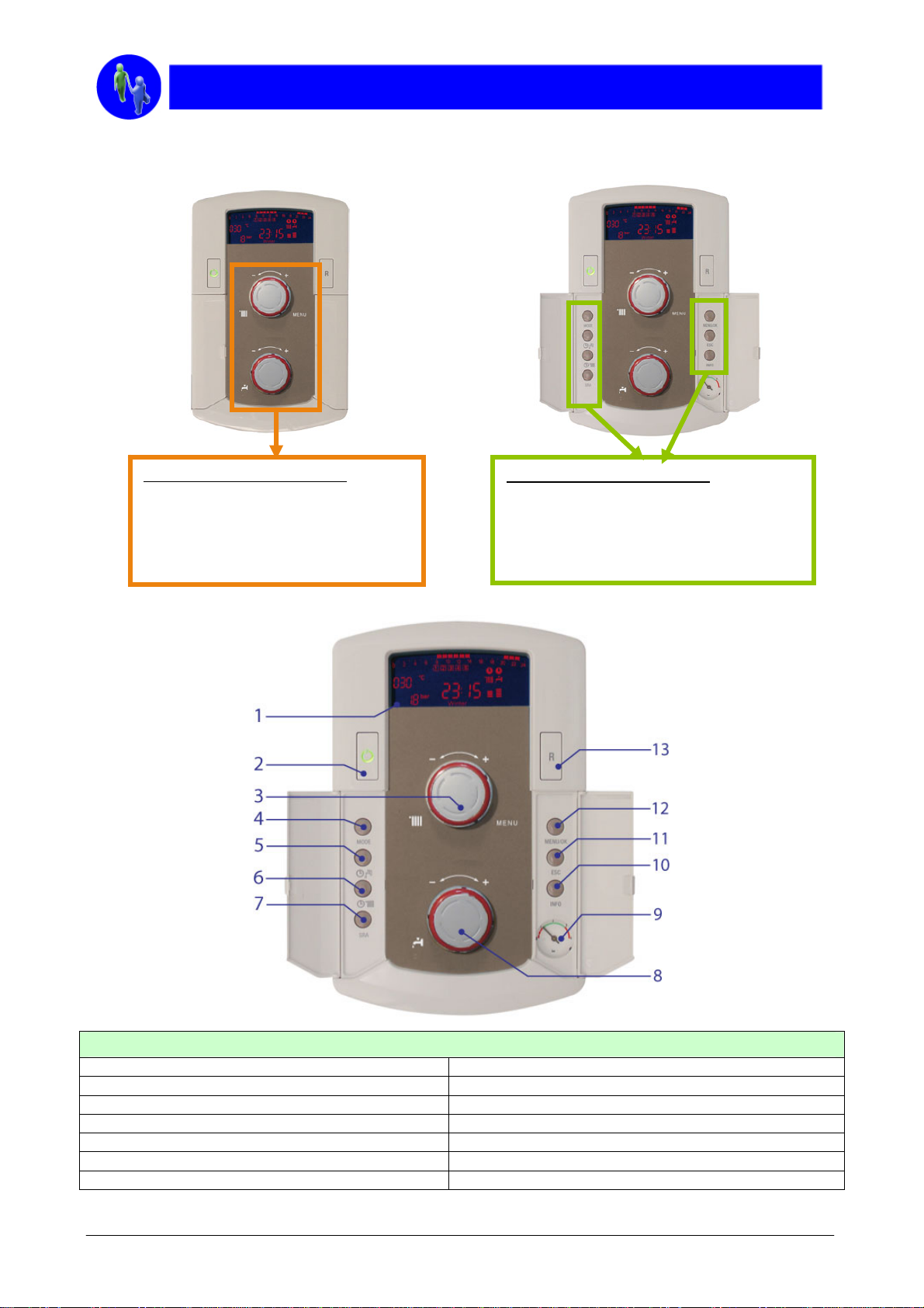
2.1 MULTILEVEL INTERFACE
Different level of accessibility:
A first level with two simple encoders
to set the standard temperature of
Central Heating and Domestic Hot
Water
2.1.1 Interface description
Different level of accessibility:
A second level for main user functions
A third level to access to the complete set
of parameters by Menu
LEGEND
1. Multifunctional LCD display 8. Domestic hot water temperature control knob
2. Main switch 9. Manometer
3. Central Heating temperature control knob 10. INFO button
4. “Mode” button 11. “Esc” button
5. DHW timer button 12. “Menu/Ok” button
6. CH timer button 13. “Reset” button
7. “Auto” function button
Page. 6 of 63
2.2 DISPLAY DESCRIPTION
The new LCD display enables the end user to check the operating status of the boiler at any time. Principal
informations are displayed on the display for a better comprehension of operation and adjustments of the boiler.
Following, the principal informations displayed on the display for a better comprehension of operation and
adjustments of the boiler.
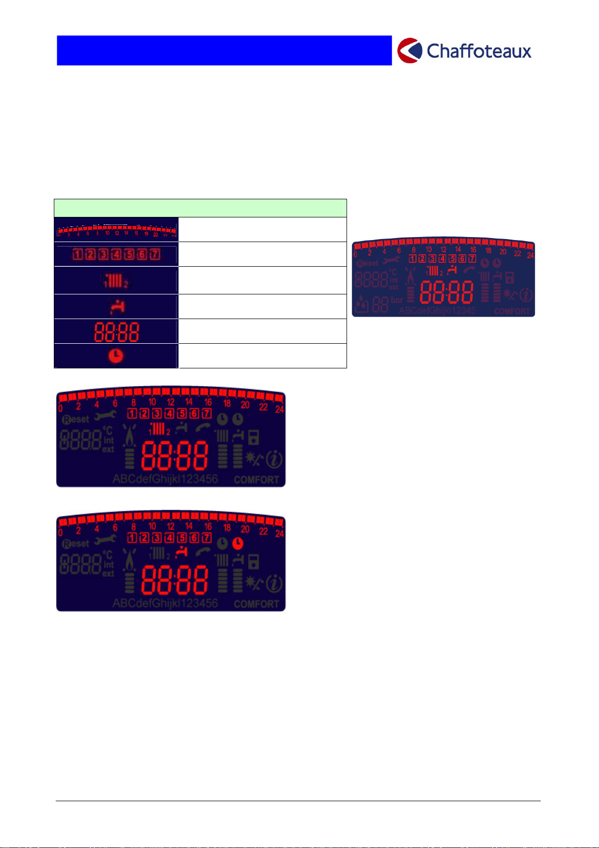
2.2.1 Week time programming zone
LEGEND
Hours programming
Week/day programming
Programming indication
(zone 1 or zone 2) for heating
Programming indication for DHW
Date and time
Hours programming activated
• Operation with weekly/schedule
Central Heating programming
The display shows (if set) the weekly/schedule
programming for up to two heating zones.
• Operation with weekly/schedule
programming
The display shows if the programming for
D.H.W. comfort is activated.
Page. 7 of 63
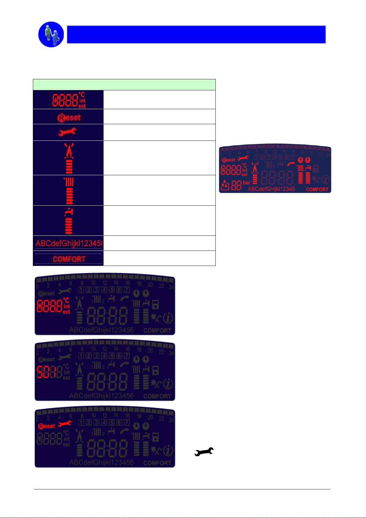
2.2.2 Functioning and diagnostic zone
LEGEND
Indication : menu setting, temperature,
default code
Reset requested
Technical assistance requested
Flame indication and power used
Heating functioning and temperature
level setting
Domestic hot water functioning and
temperature level setting
Clear text for all information
Comfort function activated
• Temperature monitoring
By pressing the INFO button, the end user can
check the indoor temperature (if a “room sensor”
is connected) or the outdoor temperature (if an
outdoor sensor is connected).
Page. 8 of 63
• Error code indication
If the boiler experiences an operating error, the
display will show the relevant error code,
thereby enabling the Technical Assistance
Service to identify the problem immediately.
• Assistance Service
If the boiler is lock-out, the display shows the
text RESET and the relevant error code. To
restore boiler operation, simply press the
RESET button on the control panel.
If the user is not able to resolve the problem,
the
advising that the Technical Assistance Service
is needed.
icon will appear on the display,

• Burner flame symbol and relative power
level
Whenever the burner is producing a flame, the flame
symbol appears on the display. The power level at
which the boiler is operating is visualised underneath
this symbol.
• “Heating” operating mode
Operation in “Heating” mode is displayed by the
radiator symbol and the operating temperature level
of the boiler.
• “Hot water” operating mode
Operation in “Hot water” mode is displayed by the tap
symbol and the operating temperature level of the
boiler.
• Informative text
At the bottom of the display, a text string guides the
user and the Technical Assistance Service through
every operation, making the boiler extremely easy to
manage.
• “Comfort” function
When the COMFORT function is active (instantaneous
production of domestic hot water) the display shows
the following indication.
Page. 9 of 63
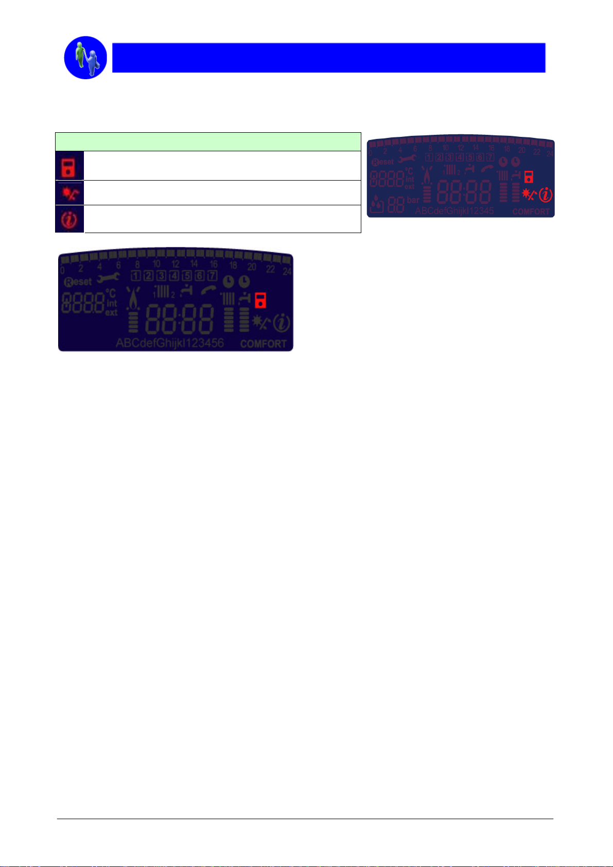
2.2.3 Peripherals control
LEGEND
Thermoregulation activated
Installation with solar panels
Info menu
• Temperature control functions
When the SRA function is activated the boiler
automatically recognizes whether a Room Sensor, an
Outdoor Sensor or a Clima Manager is connected to
the system, adjusting its operation for getting the best
efficiency and comfort.
Page. 10 of 63
2.3 INFORMATION SYSTEM
The simple and practical key information is very useful for the customer and the service after sale
Simply by pressing the “INFO” button, the
end user may immediately view a whole
range of informations which are necessary
to the correct operation of the boiler.
To move from one piece of information to the
next, press again the “INFO” button. The text
string at the bottom of the display indicates
which information is being shown.
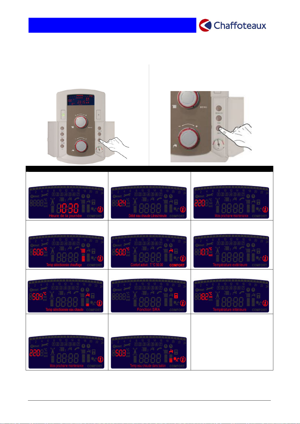
“INFO TOP” SYSTEM DISPLAY EXAMPLES
• Time of day • Hot water flow rate (litres/min) • Telephone number and
name of Assistance Centre
• Set heating temperature • COMFORT function activated
with hot water at 50°C
• Outdoor temperature °C (if an
outdoor sensor is connected)
• Set hot water temperature • SRA function enabled • Internal temperature °C
• Set number of days until the
next scheduled maintenance
operation
• Hot water temperature
inside the solar indirect
cylinder
Page. 11 of 63
2.4 SELF-CHECK FUNCTION
TALIA boiler monitors its own functions and operation status by means of a latest-generation self-check
system.
The display clearly indicates any anomalies and suggests what to do in the simplest way. It also helps the
Technical Service to find the cause of the fault showing an error code, together with an explanation of the
type of malfunction.
We have two types of information:
• Malfunctions that CAN BE RESET BY END USER without an intervention of Technical Service;
• Malfunctions that CANNOT BE RESET BY END USER and needs an intervention of Technical Service.
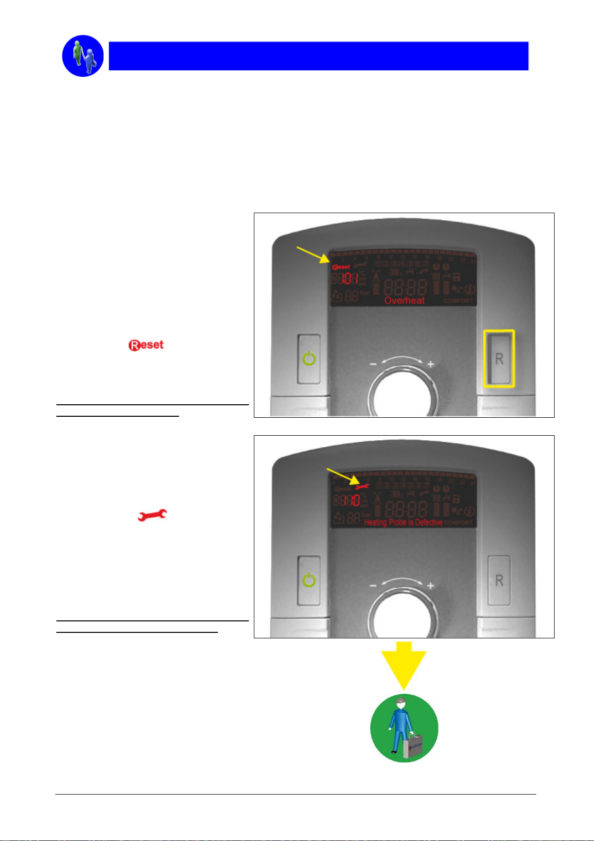
2.4.1 Malfunctions that can be reset by
end user
Let’s see how the boiler reacts in the case
of an error that can be reset (for example,
when the safety thermostat switches the
system off).
This thermostat intervenes when the
temperature of the heating water reaches
105 °C, to make sure that no damage is
caused to any part of the boiler.
The error code: (in this case, the number
101) and the “
The display also gives a description of the
problem (in example using the word
“Overheat”).
” flash alternately.
When the reset key is pressed, the boiler
returns to normal operation.
2.4.2 Malfunctions that cannot be reset
by end user
When there is a NO RESET error , such as
a malfunction of the heating-water delivery
probe, the display shows the error code: in
this case, the number 110 flashes
alternately with a “
” symbol.
The display gives a description of the
problem, (in example Heating Probe Is
Defective).
In this case, the error cannot be reset and
an intervention of Technical Assistance is
required (press INFO button to show the
name and telephone number).
When the fault has been repaired, the
boiler will return to normal operation.
Page. 12 of 63
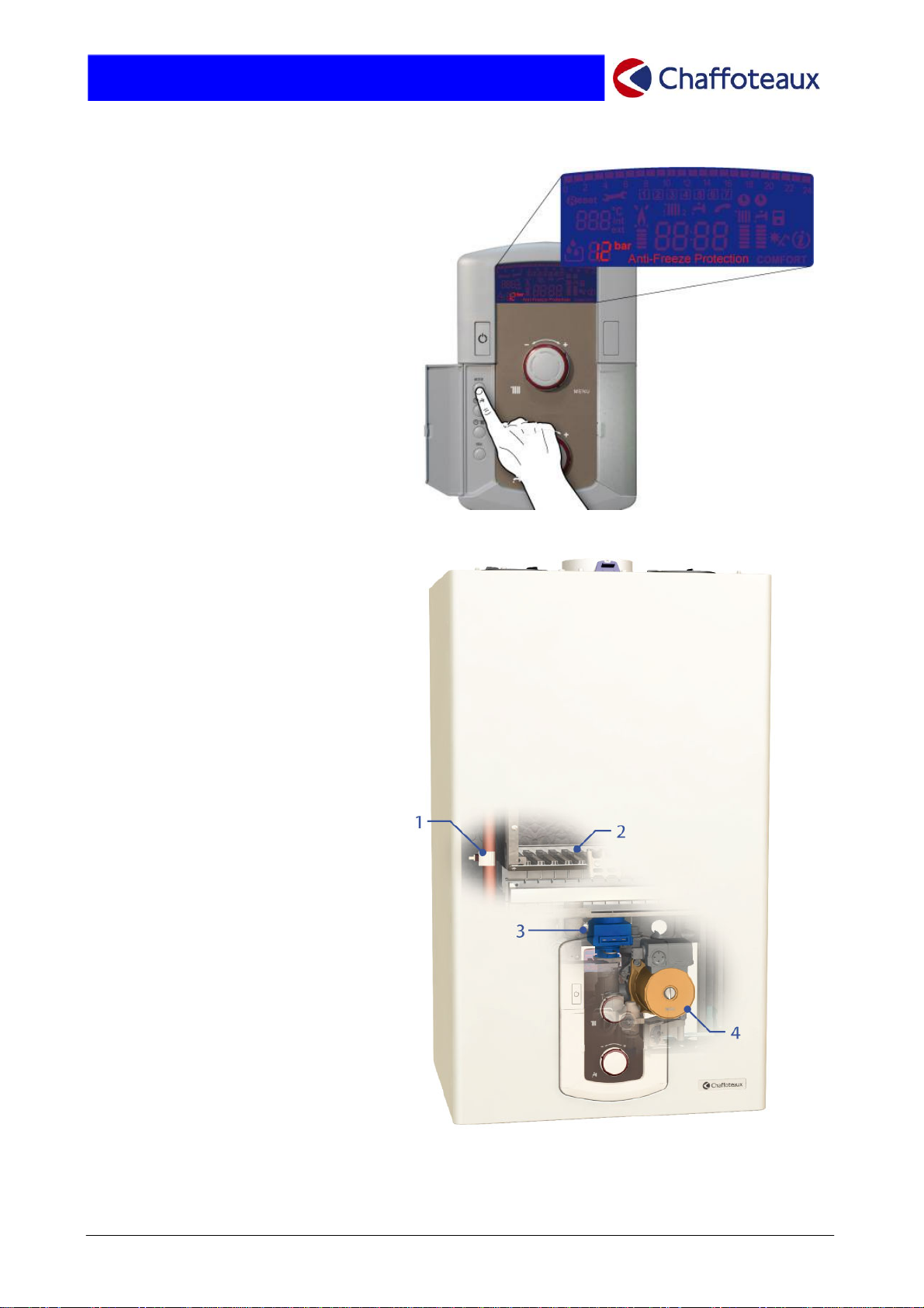
2.5 “ANTIFREEZE” FUNCTION
TALIA boiler is fitted with an AntiFreeze Protection system for the
central heating and the hot water
systems.
THIS FUNCTION DISABLE ANY
HEATING REQUEST.
In order to activate it, to repeat
press key MODE until that the
display will show:
If the temperature detected by the
“main heat exchanger probe” (1)
ranges between 3°C and 8°C, the
pump (4) runs and the 3 way valve
(3) switches alternatively its
position from domestic hot water to
central heating.
If, after 20 minutes, this
temperature remains between 3°C
and 8°C, also the BURNER (2)
turns on, supplied with minimum
power until raises
Page. 13 of 63
2.6 DHW COMFORT
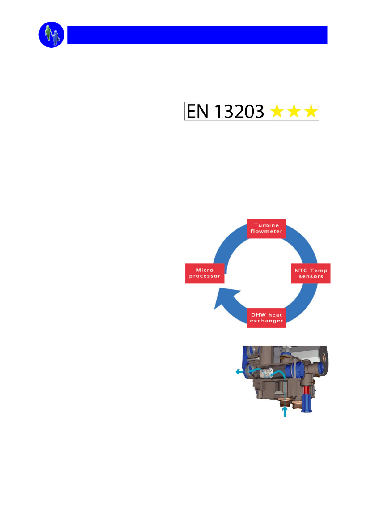
2.6.1 DHW performances & certification
The hot water production represents the most important value for any boiler and the TALIA has achieved
successfully the best level according to EN13203 – part 1 (performance of DHW delivery) in terms of:
• SPECIFIC RATE
• TEMPERATURE STABILITY
• NO WAITING TIME
• MINIMUM NOMINAL WATER FLOW RATE
TALIA satisfies not only the EN13203-part1.
It take into consideration also the need of the end user in terms of saving according to EN13203-part 2, with
the following checks:
• ENERGY CONSUMPTION IN STAND BY MODE
• ENERGY RECOVERED BY THE USEFUL WATER
• GAS ENERGY
• ELECTRICAL ENERGY
• AUXILIARY ENERGY COSUMPTION WITH THE OFF MODE.
2.6.2 The MSC system
The new system MSC (Multi Modulation Sanitary
Control), bring the best answer in term of DHW
waiting time, temperature stability even with fast,
successive tapping or with small water flow
demand. This is the most severe test for a boiler.
The new system MSC guaranties moreover the optimization of the
boiler management thanks to his progressive intelligence and the new
flow sensor with turbine is able to adapt instantaneously the boiler
output according to efficiency needed minimizing the consumption
The turbo sensor advantages:
perfect gas power adaptation to the DHW flow rate
DHW regulation more sensitive
very quick answer time
low overheating or downheating during transient water flow rate
Not sensitive to hammer shock
Repeatability
Save time and energy
30 signals/second transmits by the turbine sensor to the microprocessor
Provides immediately hot water even at reduce flow rates
Page. 14 of 63
2.6.3 DHW timer program
A saving even more important and subsequently achievable through the weekly DHW programming, built in
on the boiler which allows the comfort customizing according to the real need of the customer.
A new function that allows setting the DHW weekly timer integrated
This function permit to maintain the temperature of the plate heat exchanger for shorter DHW waiting
time.
It’s possible to program period of reheating for each day.
Page. 15 of 63

2.7 SOLAR PREDISPOSITION
Natural circulation solar
or centralized
solar installation
Serie solution
with combi boiler
& forced circulation
Parallel solution
with heating only boiler
& forced circulation
Page. 16 of 63
p
2.8 HEATING COMFORT
2.8.1 Heating performances & certification
In line with the most severe European standard in term of energetic efficiency, Talia is certified *** according
to the European standard 92/42/EEC, one certificate which offer also a guaranty of saving.
This result thanks to the quality of the components and the intelligence of the boiler capable to optimize the
performances of the combustion & hydraulic group equipped by
• New burner
• New primary exchanger
• Modulating fan
• Modulating pump
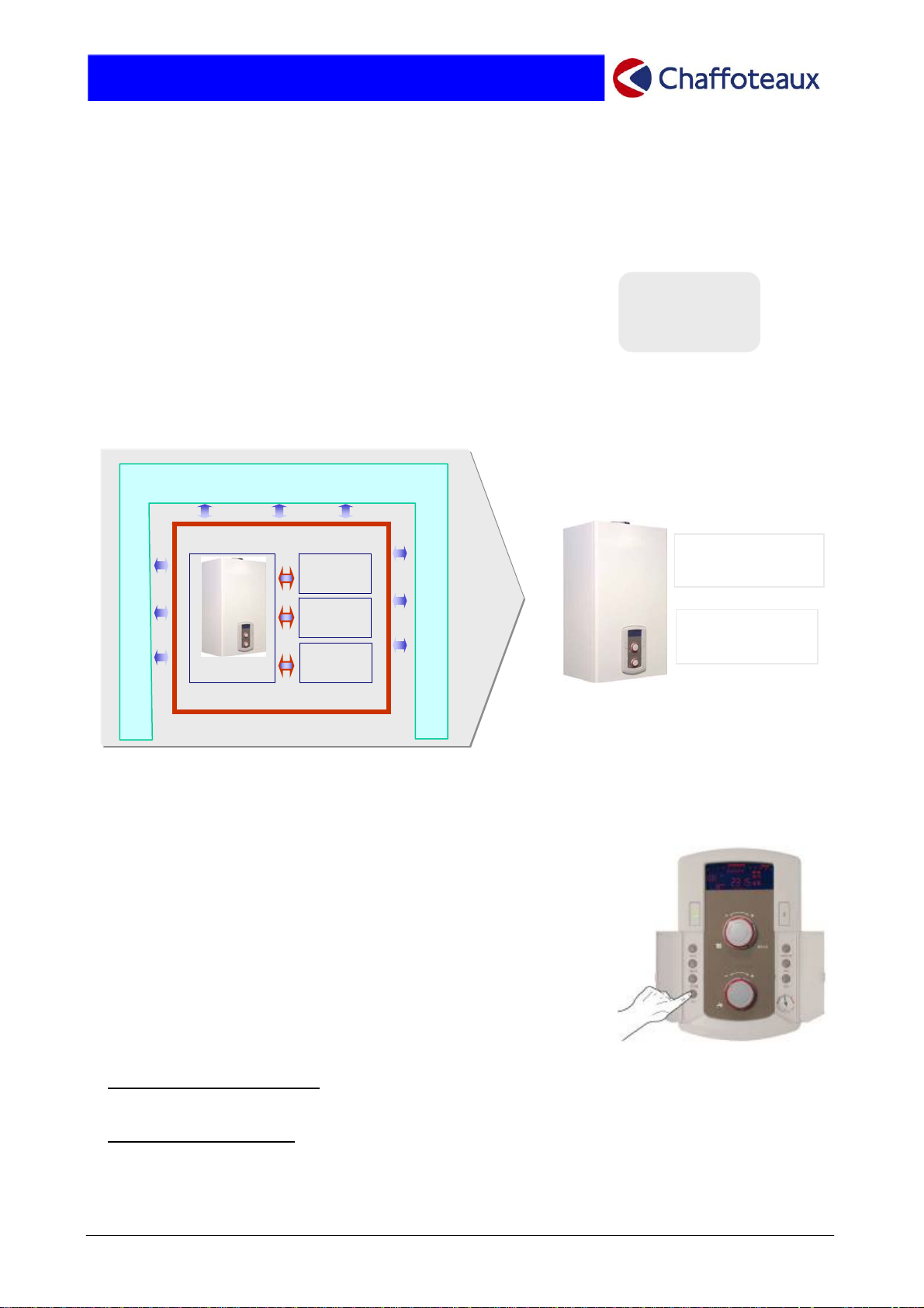
2.8.2 System approach
The boiler value is measured by the capability to give the right answer to the specific request independent of
the change of the external (climatic) or internal condition.
Climatic conditions
Ambient conditions
Boiler
erformances
Zone 1
Zone 2
Zone 3
2.8.3 Thermoregulation
The SRA function (new Automatic Regulation System), permits the access to the thermoregulation world
without any worry in terms of explanations, management or installation
Efficiency
& Saving
thermoregulation
Hydraulic
distribution
The SRA function is the essence of the project logic:
o Ease of use (only one push on the integrated button)
o Customized comfort in heating guaranteed.
The new intelligence of the boiler will manage in auto-adaptative way the
main values of the boiler, to reach the best result in terms of requested
comfort in every installations & conditions.
► Central heating temperature:
It will adjust automatically and permanently according to the outside temperature and/or of the temperature
in the house.
► Boiler power modulation:
It will adapt the power to the burner according to the operating conditions.
Page. 17 of 63

Depending on the different installation configuration
Basic
with room thermostat (on/off)
Climatic
with external probe & room
thermostat on/off
Ambient
with modulating room
sensor
Complete
thermoregulation
Comfort
level
++
+++
++++
++++
Saving
level
The new SRA function assures to reach the following results:
Maximum personalisation
Best efficiency
Maximum comfort
Acoustic comfort
Better reliability
Less environment impact
Heating distribution
A large range of accessories for a large range of heating configurations.
The installer can give easily to the client the best solution for each need
Monozone
For big
installation
Double zone
Triple zone
Mono
temperature
Multi
temperature
Page. 18 of 63
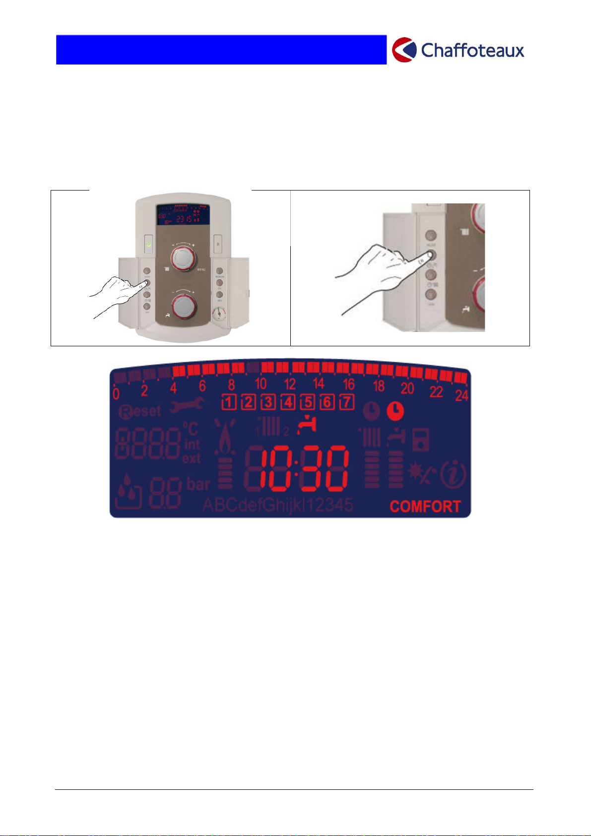
2.8.4 Built-in weekly timer.
The new electronic controls enable the user to programme the boiler at intervals of 15 minutes for every
single day of the week.
For this type of operation, it is not necessary to purchase an external timer. Programming is
activated/desactivated by pressing the button.
The end user can use 3 pre-set programmes which may obviously be easily customised by the user.
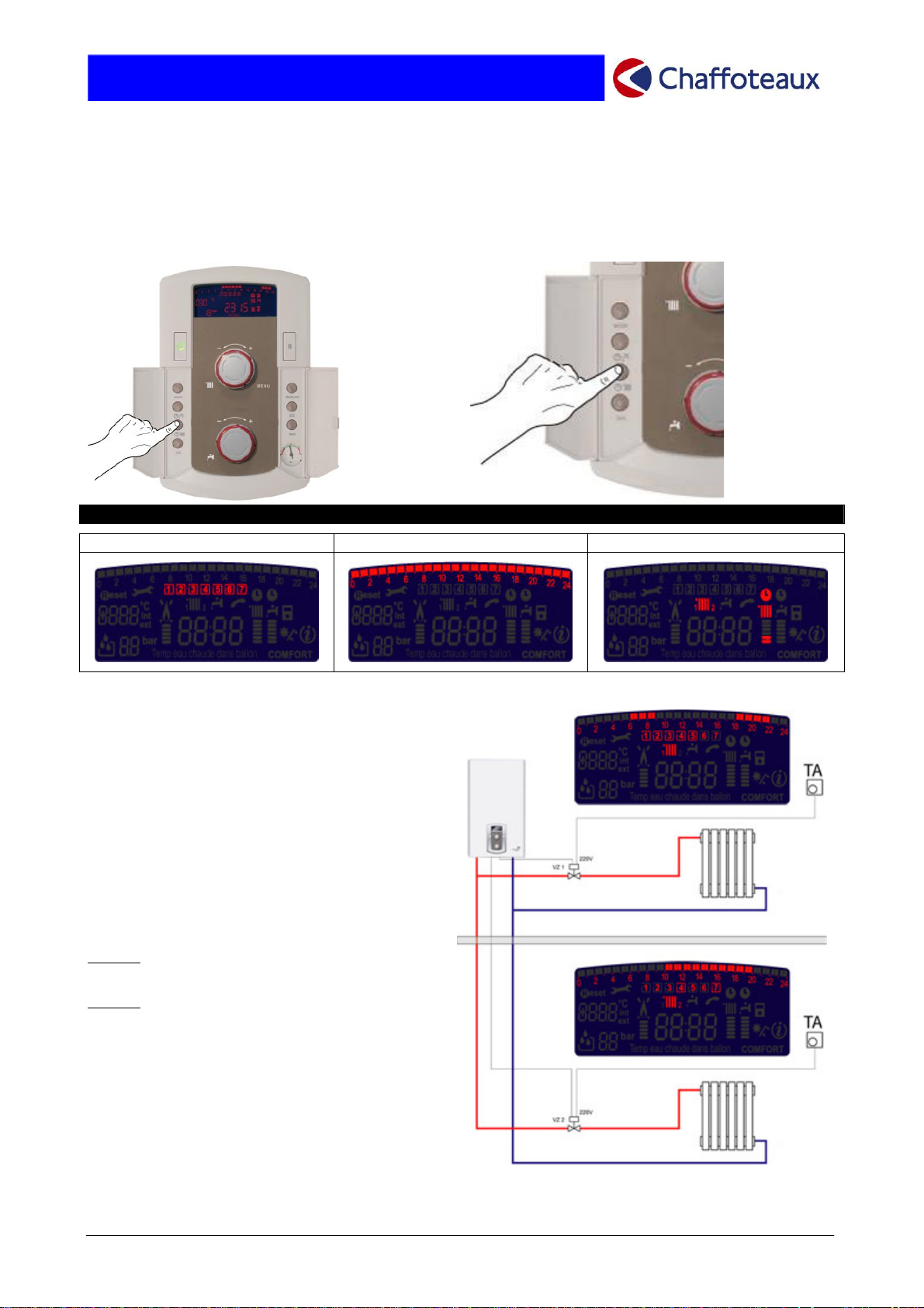
PROGRAMMING: THE DISPLAY
.
Weekly programming 24-hour programming Controlling 2 zones
An heating system which has been divided into
two zones is shown.
TALIA boiler is able to control timer programming
(intervals of 15 minutes) and weekly programming
an independent and specific way for each
programme.
EXAMPLE:
Zone 1
: from Monday to Friday, between 6.00
and 9.00 and 18.00 and 22.00.
Zone 2
: Thursday and Sunday, between 10.15
and 19.45.
Page. 19 of 63
 Loading...