

Page 1

Training manual :PIGMA Gal Evo
Training
Handbook
FAMILY: Wall-mounting gas boilers
TYPE: Conventional design
NAME: PIGMA Gal Evo PT IT RDC
TRADE MARK: CHAFFOTEAUX
Issue : 1V0 24.07.2012
Technical support for market
Page 2

Page. 2 of 73
Training manual :PIGMA Gal Evo
Up-date lliisstt
.
1V0
24/07/12
MP VERSION
DATE
NAME
CHANGES ENTERED
Page 3

Page. 3 of 73
Training manual :PIGMA Gal Evo
INDEX
1 GENERAL INFORMATION .................................................................................................................................. 5
1.1 SIZE & DIMENSIONS ........................................................................................................................ 5
SEALED CHAMBER OVERALL VIEW (FF) ................................................................................................... 6
1.2 OPEN CHAMBER ASSEMBLY VIEW (CF) ...................................................................................... 7
1.3 CONTROL BOARD .......................................................................................................................... 8
1.3.1 General Indications ...................................................................................................................................... 8
1.4 SCREEN.............................................................................................................................................. 9
1.4.1 indications on display scree .......................................................................................................................... 9
1.4.2 Indications of operating modes displayed on the screen ............................................................................ 11
2 OPERATION .......................................................................................................................................................... 12
2.1 HEATING MODE ............................................................................................................................ 12
2.1.1 Assembly view of system in heating mode .................................................................................................. 14
2.2 SANITARY MODE ............................................................................................................................. 15
2.2.1 Assembly view of sanitary mode ................................................................................................................. 17
SOLAR SENSOR SANITARY MODE .......................................................................................................... 17
3 SPECIAL FUNCTIONS......................................................................................................................................... 18
3.1 FLUE CLEANER” FUNCTION ........................................................................................................... 18
3.2 “COMFORT” FUNCTION ................................................................................................................... 20
3.3 “ANTIFREEZE” FUNCTION .............................................................................................................. 22
3.4 “WATER FLOW CHECK” ............................................................................................................... 23
3.5 AIR PURGE” FUNCTION .................................................................................................................. 26
3.6 “SELF ADAPTIVE HEATING RESTART DELAY” .......................................................................... 27
4 HYDRAULIC BLOCK .......................................................................................................................................... 28
4.1 RIGHT HYDRAULIC BLOCK .................................................................................................................. 29
4.2 LEFT HYDRAULIC BLOCK .................................................................................................................... 30
4.3 WAY VALVE ....................................................................................................................................... 31
4.3.3-way valve motor ............................................................................................................................................... 31
4.4 PLATE TYPE HEAT EXCHANGER ................................................................................................ 32
Temperatura limite anticalcare ................................................................................................................................ 32
4.5 PUMP UNIT ....................................................................................................................................... 33
4.5.1 PUMP speed check ..................................................................................................................................... 33
4.5.2 Post-circulation. ......................................................................................................................................... 34
4.6 DRAIN PORT & PLUG ...................................................................................................................... 34
4.7 BY-PASS VALVE .............................................................................................................................. 35
4.8 PRIMARY HEAT EXCHANGER ............................................................................................................ 35
4.9 PRESSURE PICK-UPS (FF ONLY) ................................................................................................. 35
4.10 HEATING LINE STRAINER ............................................................................................................ 36
4.11 HEATING EXPANSION VESSEL ................................................................................................... 37
4.12 SANITARY FLOW RATE ................................................................................................................ 37
4.13 TEMPERATURE SENSORS .......................................................................................................... 39
5 GAS LINE ............................................................................................................................................................... 40
5.1 GAS VALVE TYPE SIT SIGMA 845 ................................................................................................ 40
5.2 SOLENOID VALVE ELECTROPNIC CONNECTION DIAGRAM. .................................................. 40
5.3 GAS REGULATIONS. .................................................................................................................... 41
5.3.1 Supply pressure check. ................................................................................................................................ 41
5.3.2 Maximum sanitary power check ................................................................................................................. 41
5.3.3 Minimum power check. ............................................................................................................................... 42
5.3.4 Soft ignition power checking ....................................................................................................................... 42
5.3.5 Clocking for heating restart aftr burner flame out ..................................................................................... 43
5.3.6 Control of maximum heating power ............................................................................................................ 43
5.3.7 TABE OF GAS ............................................................................................................................................ 46
5.4 BURNER ........................................................................................................................................ 47
5.5 FLUE EXHAUST PORTS (SUCTION TYPE MODEL) ........................................................................ 48
5.6. AIR PRESSURE SWITCH (SUCTION CAP TYPE DESIGN) ...................................................................... 48
5.6 EXTRACTOR (SUCTION CAP TYPE DESIGN)....................................................................................... 49
Page 4

Page. 4 of 73
Training manual :PIGMA Gal Evo
5.7.1.POST-VENTILATION ................................................................................................................................ 49
5.6.1 SPOTT UNIT ( MODEL CF) ...................................................................................................................... 50
5.7 FLUE EXHAUST / MODEL CF ........................................................................................................ 50
5.8 SUCTION CUP OUTLET / SUCTION CUPS MODELS / POSSIBLE CONFIGURATIONS ...................................... 51
EXHAUST SYSTEMS (SEALED CHAMBER FF) ............................................................................................... 51
6 ELECTRONIC PCBS ............................................................................................................................................ 55
MAIN CARD ................................................................................................................................................. 55
Electronic Wiring Diagram ...................................................................................................................................... 55
6.1.1 Diagramme électronique FF boiler ............................................................................................................ 56
6.1.2 Diagramme électronique CF boiler ............................................................................................................ 58
7 MENU AND SETTING .......................................................................................................................................... 59
7.1 USER MENU ...................................................................................................................................... 59
7.1.1 GUIDE TO NAVIGATING IN THE MENUS ............................................................................................. 59
7.1.2 MENUS ....................................................................................................................................................... 60
7.2 COMPLETE MENU ........................................................................................................................ 61
7.2.1 Menu 0 : Network ....................................................................................................................................... 61
7.2.2 MENU 2 : BOILER PARAMETERS ............................................................................................................ 61
7.2.3 MENU 4 : ZONE 2 PARAMETERS ............................................................................................................ 63
7.2.4 MENU 5 : ZONE 2 PARAMETERS ............................................................................................................ 63
7.2.5 MENU 6 : ZONE 3PARAMETERS ............................................................................................................. 64
7.2.6 MENU 8:SERVICE PARAMETER .............................................................................................................. 65
8 ERROR CODES ..................................................................................................................................................... 67
8.1 BOILER PROTECTION SYSTEMS. ............................................................................................... 67
8.1.1 Error codes ................................................................................................................................................. 67
9 FIRST STARTING AT WORK ............................................................................................................................ 69
10 PERIODICAL CHECKS .................................................................................................................................. 70
11 DONNEES TECHNIQUES URBIA................................................................................................ ................. 72
11.1 PIGMA CF ........................................................................................................................................ 72
11.1 PIGMA FF ......................................................................................................................................... 73
Page 5

Page. 5 of 73
Training manual :PIGMA Gal Evo
1 GENERAL INFORMATION
1.1 SIZE & DIMENSIONS
LEGEND
A
System delivery
B
Hot water outlet
C
Gas inlet
D
Cold water inlet
E
Heating system return
PIGMA EVO
PIGMA SYTEM
EVO
Page 6

Page. 6 of 73
Training manual :PIGMA Gal Evo
SEALED CHAMBER OVERALL VIEW (FF)
LEGEND
1
Flue Manifold
16
Filling Tap
2
Air pressure switch
17
CH Filter
3
Air pressure switch pressure intake condensate exhaust
18
Pump
4
Main Heat Exchanger
19
Heating minimum pressure switch
6
NTC1 heating delivery temperature probe
20
NTC2 heating return temperature probe
7
Burner
21
3 Way Valve
8
Ignition electrodes
22
Detection electrode
9
Gas valve
23
Ceramic Fibers
10
Spark generator
24
Combustion Chamber
12
3 bar safety valve
25
Expansion Vessel
13
Secondary Heat Exchanger
26
Modulating Fan
14
CH draining tap
27
Combustion Analysis Test Point
15
Proportional sanitary flow meter
Page 7

Page. 7 of 73
Training manual :PIGMA Gal Evo
1.2 OPEN CHAMBER ASSEMBLY VIEW (CF)
LEGEND
1
Flue Manifold
14
CH draining tap
2
Flue Control Thermostat
15
Proportional sanitary flow meter
3
Flue Hood
16
Filling Tap
4
Main Heat exchanger
17
CH Filter
6
NTC1heating delivery temperature probe
18
Pump
7
Burner
19
NTC2 heating return temperature probe
8
Ignition electrodes
20
3 Way Valve
9
Gas valve
21
Detection electrode
10
Spark generator
22
Ceramic Fibers
12
3 bar safety valve
23
Combustion Chamber
13
Secondary Heat Exchanger
24
Expansion Vessel
Page 8
Page. 8 of 73
Training manual :PIGMA Gal Evo
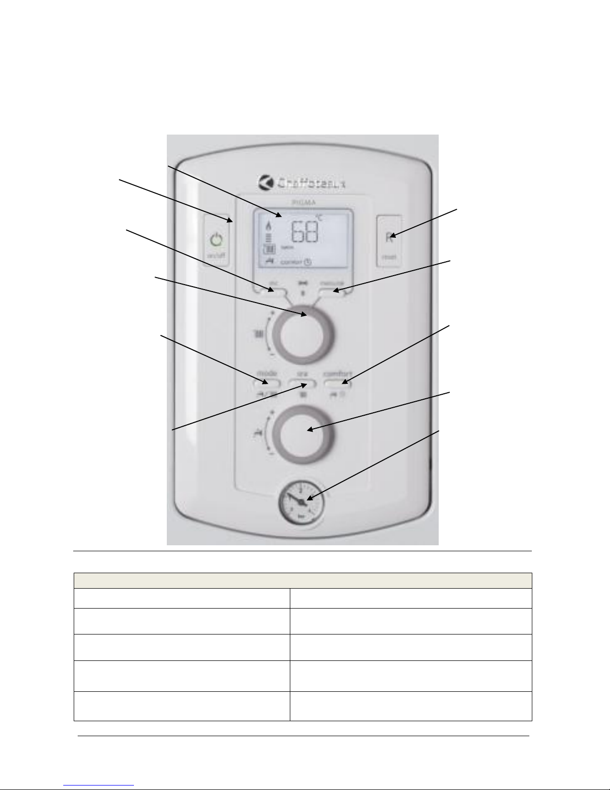
1.3 CONTROL BOARD
1.3.1 General Indications
LEGEND
1 Dysplay
7 manometer
2 Start / Stop button
8 Push button for Sanitary
3 « ESC » button
9 Push button sanitary CONFORT
4 Push button for heating
10 Access to menu /validation push-button
5 Select push button for modes : summer /
winter / anti-frost l
11 Touche « Reset
1
2
4
9
6
8
7
5
3
10
11
Page 9

Page. 9 of 73
Training manual :PIGMA Gal Evo
6 SRA push button
1.4 SCREEN
1.4.1 indications on display scree
ICON
DESCRIPTION
Navigation
Navigation Parameter
Code
Default Code
Flame and level of power
Flame error
Heating disable
Heating enable
Sanitary disable
Sanitary enable
Comfort function
Boiler OFF and Anti freeze function enable
Anti-freeze function activate
SRA activate
Solar system
Page 10

Page. 10 of 73
Training manual :PIGMA Gal Evo
Page 11

Page. 11 of 73
Training manual :PIGMA Gal Evo
1.4.2 Indications of operating modes displayed on the screen
During the working of the appliance, it’s possible to verify the status of the boiler:
ECRAN
DESCRIPTION
ETAT CHAUDIERE
Stand-By
STAND-BY. No request.
Adjustment of
heating request
Adjustment of the heating request by the button n° 4.the
number indicates the set point. They blink during 5 s
Heating mode,
burner ON and SRA
function
The radiator who symbolise the heating circuit is surrounded,
that fame is enable and there is an indication of the level
power
Heating mode,
burner OFF and
SRA function
End of the heating request, the boiler is OFF but there is a
post-circulation of 3 min (default value)
Adjustment of
sanitary request
Adjustment of the sanitary request by the button n° 8.the
number indicates the control temperature. They blink during
5 s
Sanitary tapping,
burner ON n
The tap who symbolise the sanitary circuit is surrounded,
that fame is enable and there is an indication of the level
power
Comfort mode,
burner ON
The boiler is operating an tank heating mode, the 2 numbers
indicate the control temperature for sanitary system
En puisage sanitaire
brûleur éteint.
End of the sanitary request, the boiler is OFF but there is a
post-circulation of 3 min (default value)
Anti-frost function
ON
The anti- frost function is activate, management with the
NTC1 delivery sensor.
Solar system
connected by E-Bus
Solar system is connected by E-Bus to the boiler
TEST mode
Combustion analysis
Purge mode
Air purge function
Page 12
Page. 12 of 73
Training manual :PIGMA Gal Evo
2 OPERATION
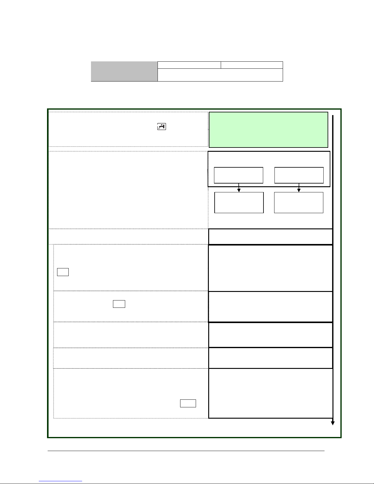
2.1 HEATING MODE
CONTROL
RANGE
35°C
85°C
Temperature readout can be viewed from screen 4
second long, each time heating button is
manipulated.
Pump is powered 7 seconds after the 3-way
valve, with a view at avoiding surge in system.
Request for Heating
3-Way Valve
powered
Pump powered
The request for heating can be initiated by :
- a room thermostat ,
- a room sensor,
- a programmer or
- an Expert Control
The character appears in this moment on the
screen.
The temperature read by the sensor on the
primary start can be viewed on the screen.
Sanitary mode is the rest position for the 3-way
valve.
When a heating request is active, the motor
driving the 3-way valve is energized for shifting
to heating mode.
The stem of the valve is then in « retracted »
position.
Extractor powered
Before activating the extractor, a check of
pressure switch status is carried out (contact
shall be in open position, otherwise default code
symbol
6 07
is displayed on the screen).
The extractor is power-supplied (model FF only).
Page 13
Page. 13 of 73
Training manual :PIGMA Gal Evo
Burner ignition
Flame detection
Ignitor and gas valve
powered
When pressure switch contact is set to closure, the
gas valve and the igniters are power supplied.
A permanent check of flow rate is developed with the
aid of 2 primary sensors (Forward & Return).
Flow rate Control
Gas valve is fed by the ignition power (adjustable by
parameter 2 20).
Flame detection is obtained by the ionization
electrode. In the event that the ionization sensor does
not sense any current during the ignition phase (8
seconds maximum), the boiler turns into safety state
and code symbol 5 01 is displayed on the screen.
Model FF only: a functional test of extractor is
performed by use of air pressure switch. If no signal is
detected after 20 seconds, the boiler turns to stand-by,
and code symbol
6 P1
is displayed on the screen.
Testing air pressure
switch
Flame detection enables the gas valve and the
extractor to carry out modulation of flame intensity
according to heat request.
Heating system output is adjustable by parameter 2
31 in operating ranges
Minimum output can be controlled directly by acting
on the gas valve.
Burner flame turn-off will take place at the following
T° values:
In the 1st min after flame detection:
T°off = set point T° + 8°C
In the 2nd min after flame detection
T°off = T° set point T° + 6°C
After the 3rd min after flame detection:
T°off = set point T° + 4°C
This logic of operation allows to avoid possible
occurrence of delayed ignitions and extinctions by
Modulation of burner
flame
Overheat Control
Overheat control is provided through a thermostat
(102±4°C) located at the outlet of the primary heat
exchanger. Resetting to be effected manually from the
control panel.
Default 1 01 is shown on screen. Reset possible when
temperature reads 87°C.
Notice. Primary start sensor (NTC1) is to control that primary temperature may not exceed set value
88°C; in this occurrence, the sensor interdicts the burner to start ignition.
If flow circulation in the heating sytem is not sufficient to fulfill the purpose, an automatic by-pass valve
can open (maximum capacity = 350 l/h).
Page 14
Page. 14 of 73
Training manual :PIGMA Gal Evo
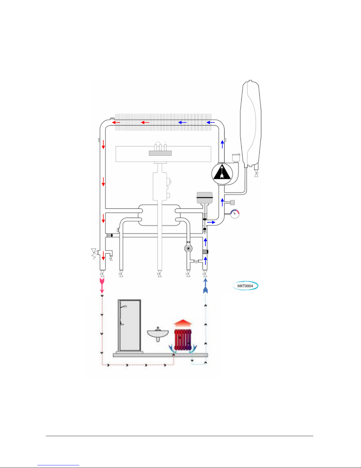
2.1.1 Assembly view of system in heating mode
Notice.
The primary start sensor (NTC1) checks to ensure that the primary circuit heat level
may never exceed 88°C in temperature; in this state, the sensor interdicts the burner
to start flame ignition.
When the circulation flow in the heating system is not enough to comply with the need ,
an autonatic by-pass valve can open ( maximum flow rate 350 l/h).
Page 15
Page. 15 of 73
Training manual :PIGMA Gal Evo
2.2 SANITARY MODE
OPERATION
RANGE
40°C
60°C
By pushing the buttons “+” o “-“,you can see on the
display (for 4 seconds) the set temperature .
HOT WATER REQUEST
FOR SANITARY
3-way valve
Heating request
ON
Heating request
OFF
Turning from
heating over to
sanitary
The 3-way valve
remains set for
sanitary
When a sanitary request is detected by the sanitary flow
meter (flow rate > 1,6 l/min), the symbol appears on
the display, together with the indication for temperature
control.
2 possibilities exist:
1. If boiler is in stand-by mode, the 3-way valve is
already set to sanitary position.
2. If boiler is in heating mode, the 3-way valve is being
fed for setting to sanitary mode.
During this change in mode, burner and pump are
both being fed.
Pump under supply
The pump is under supply.
Extractor powered
Prior to imparting command signals to the extractor,
a check is made to the pressure switch (contact
must be set to open position, otherwise default code
6 07
is displayed).
Extractor remains under power supply (FF model
only).
Air pressure switch
Control
Checking closure of air pressure switch contact in 20
seconds, otherwise
6 P1
is displayed.
(for model FF only ).
When the pressure switch contact is closed, gas
valve and igniters are both under power supply.
Ignitor and gas valve
powered
The gas valve is supplied with ignition power input
(adjustable by parameter 2 20).
Ignition of burner
Flame detection is carried out by the ionization
electrode. In the event where for the time of the
ignition cycle (8 seconds maximum), the ionization
sensor does not detect any input power, the boiler
turns into stand-by, and code symbol 5 01 is
displayed on the screen
Burner flame
test
Page 16

Page. 16 of 73
Training manual :PIGMA Gal Evo
.
A permanent check of flow rate is developed with the
aid of 2 primary sensors (Start & Return).
Flow rate Control
Burner performs flow modulation from minimum
output up to maximum output (control over gas
valve).
Burner will flame out if temperature read by the
sensor for primary return NTC2
Burner Modulation
Overheat Control
Control by burner is performed over the sensor for
primary return NTC2. Burner flame goes out when
temperature reading by primary return sensor is by
4°C higher than set point value.
Temperature Control
Overheat control is provided through a thermostat
(102±4°C) located at the outlet of the primary heat
exchanger. Resetting to be effected manually from the
control panel.
Default 1 01 is shown on screen. Reset possible when
temperature reads 87°C.
If there is a bad circulation through the heating system, the
automatic by-pass can be opened (max capacity 350 l/h).
Page 17

Page. 17 of 73
Training manual :PIGMA Gal Evo
2.2.1 Assembly view of sanitary mode
SOLAR SENSOR SANITARY MODE
Boiler is fitted with a solar sensor.
On occasion of a sanitary water draw-off from the solar hot
water tank , the conrol of burner is accomplished in the
following manner :
the solar sensor will enable or not, the burner to operate
according to the specified sanitary temperature values
set to the Control Board (see Table on the right).
Setpoint T°for sanitary
set on Control Board
[°C]
Ignition T° read by solar
sensor
[°C]
36
36
40
39
45
43
50
47
55
50
60
54
Inlet
Example :
Page 18

Page. 18 of 73
Training manual :PIGMA Gal Evo
3 SPECIAL FUNCTIONS
3.1 FLUE CLEANER” FUNCTION
This function is used to perform proper boiler combustion analysis and maximum and minimum gas
calibration.
Follow the instructions below to enable it:
PRESS
DISPLAY
The display will show this indication
Press Reset button for 5 continuous seconds
With the boiler on “Winter” mode, the 3-way valves is positioned on “heating” and the burner turns on
even without heating requested.
With the boiler on “summer” mode:
o without sanitary demand the burner turns on in heating;
o with sanitary demand the burner turns on in sanitary.
The delivery temperature (NTC1) is checked during the “Flue cleaner” function, as follows:
“summer” mode → Off: 86°C; On: 81°C;
“winter” mode → Off: 89°C; On: 84°C.
Three different powers can be selected when the function is enabled
PRESS
DISPLAY
POWER
Turn the knob
anticlockwise
Maxi power in
heating mode
Max power in
sanitary mode
Turn the knob
anticlockwise
Minimum power
Page 19

Page. 19 of 73
Training manual :PIGMA Gal Evo
To exit the “Flue cleaner” function, press the RESET button. However after 30 minutes the function will be
disabled automatically.
Page 20

Page. 20 of 73
Training manual :PIGMA Gal Evo
3.2 “COMFORT” FUNCTION
This function allows the user either to activate or not the function « temperature holding in the sanitary water
reserve tank.
At workshop level this function remains active over a time range 24h/24h, 7days/7days. Wording
« COMFORT », is displayed at the screen bottom and it enables adapting Temperature Hold in the sanitary
reserve according to user’s needs.
To program it, comply with the directions given below :
Whit the menu 250, it’s possible to validate this function COMFORT:
0 = Disable
1 = timer
2 = Always activate
How to Program the comfort function
Workshop outgoing
configuration.
The term
« COMFORT »indicates that
temperature holding
condition is set
permanently..
Programming COMFORT
function
pressing Comfort button
allows setting this function n
L’icon « Timer » is displayed
on the screen.
Function disabling
Pressing this button for the
third time turn off completely.
The boiler is an instant
mode. The screen does not
indicate the clock symbol
any more nor working
Comfort mode
Page 21

Page. 21 of 73
Training manual :PIGMA Gal Evo
The operating range is variable and depends on the temperature set for the sanitary mode:
TEMP. SET FOR SANITARY MODE
OFF TEMPERATURE
ON TEMPERATURE
36
40
34
37
41
35
38
42
36
39
44
38
40
45
39
41
46
40
42
47
41
43
49
43
44
50
44
45
51
45
46
53
47
47
54
48
48
56
50
49
58
52
50
59
53
51
61
55
52
63
57
53
64
58
54
66
60
55
68
62
56
70
64
57
71
65
58
72
66
59
73
67
60
74
68
Page 22

Page. 22 of 73
Training manual :PIGMA Gal Evo
3.3 “ANTIFREEZE” FUNCTION
This function is enabled only if the ON/OFF selector is turned on position ON. It is operated by means of
the temperature detected by the heating delivery probe (NTC1).
CONDITION
EVENTS
TIME
1
ST
CASE
The temperature
detected by probe
NTC1:
Ranges between 3°C
and 8°C
- The PUMP is supplied on speed III
- The 3-WAY VALVE alternatively
switches the position of the shaft from
1 minute on “heating” to 1 minute on
“sanitary” mode
- The DISPLAY shows the icon
Until the
NTC1
temperature is
9°C
If, after 20 minutes,
the CONDITIONS described in the 1st CASE are still present (3°C<NTC1<8°C)
automatically check the EVENTS of the 2nd CASE
CONDITION
EVENTS
TIME
2
nd
CASE
The temperature
detected by probe
NTC1:
Is below 3°C
- The BURNER turns on, supplied with
minimum power;
- The 3-WAY VALE is positioned on
“sanitary” and switch every 30 s
DHW/CH
- When the temperature is 40°C the
burner turn OFF. For 15 minutes the
boiler maintain the temperature
between 35°C and 40°C
- After 15 minutes there is 2 minutes of
post circulation in heating
- Into 90 minutes if the temperature
decreases again less than 8°C the
burner switch on immediately.
- The DISPLAY shows the icon .
Until the
NTC1
temperature is
30°C
If the NTC1 delivery probe is not working (open or short circuit) the “antifreeze” function check is followed by
the NTC2 heating return probe but in these cases only the pump works (the burner doesn’t light). The display
doesn’t show the antifreeze enabling code, but the error code of the NTC1 open or short circuit 1 10 or
1 11.
The antifreeze is enabled even if the NTC2 return probe is not working (open or short circuit) but only the
pump works (the burner doesn’t light). In this case the display doesn’t show the antifreeze enabling code, but
the error code of the NTC2 open or short circuit 1 12 or 1 13.
The antifreeze is enabled even if the boiler is shutdown due to no flame detection 5 01 or blocked for over
heat 1 01, but in these cases only the pump works (the burner doesn’t light), and the display shows the error
code of blocking and not the antifreeze enabling one.
If there is an interruption of the power supply, the boiler maintains in memory all the setting and when the
power supply is on the boiler returns in the condition that had before the turning off.
Page 23

Page. 23 of 73
Training manual :PIGMA Gal Evo
3.4 “WATER FLOW CHECK”
Check
When
What happens
Gradient Tman > 7°C/sec
(checked every 100ms)
Check always with the
flame on, except during
the first 4 seconds after
flame detection.
1. Immediate safety shutdown 1 P1:
- 10sec of post-circulation
- 10 sec of post-ventilation
The boiler restarts after 10sec.
2. If the error occurs other 2 times within the
following 4 minutes it will be shutdown 1 03 :
- 20sec of post ventilation
- 1min of post circulation.
Gradient Tman > 20°C/sec
or
Gradient Trit > 20°C/sec
(checked every 100ms)
Check always with the
flame on, and up to 7 sec
after each turn off for
temperature set or safety
shutdown.
1. Shutdown 1 04:
- 20sec of post ventilation
- 1min of post-circulation.
Tman – Trit > 55°C
Check always with the
flame on, and up to 7 sec
after each turn off for
temperature set or safety
shutdown.
1. Immediate safety shutdown 1 P2:
- 10sec of post-circulation;
- 10sec of post ventilation.
After 10sec the boiler restarts.
2. If within 4 minutes from the first safety
shutdown the defect occurs again there will be
a safety shutdown 1 P2 :
- 10sec of post-circulation;
- 10sec of post ventilation.
After 10sec the boiler restarts but the timer is
zeroed.
3. If within 4 minutes from the first safety
shutdown the defect occurs again it will be
shutdown 1 05 :
- 20sec of post ventilation
- 1min of post circulation.
Trit > Tman + 10°C
Check always with the
flame on.
1. If the defect occurs for 20 continuous seconds
there will be a safety shutdown 1 P3 :
- 10sec of post-circulation;
- 10sec of post ventilation.
After 10sec the boiler restarts.
2. If the defect occurs for 20 continuous seconds
another 2 times within 4 minutes it will
shutdown 1 06 :
- 20sec of post ventilation;
- 1min of post circulation.
Trit > Tman + 30°C
Check always with the
flame on.
20sec of post ventilation;
- 1min of post circulation
“
Page 24

Page. 24 of 73
Training manual :PIGMA Gal Evo
ON
OFF
ON
OFF
ON
OFF
Burner
Extractor
1 04
Evolvement of start T° or return T° > 20°C/sec
>20°C/sec
Evolvement
<20°C/sec
1 04
<7 sec
60 sec (post-circ.)
20 sec (post-vent.)
Case “A”
Case “B”
20 sec (post-vent.)
60 sec (post-circ.)
Pump
ON
OFF
ON
OFF
ON
OFF
Burner
Extractor
1 P1
Evolvement of start T° > 7°C/sec
ON
OFF
>7°C/sec
Times
Evolvement
<7°C/sec
1 03
1 P1
10 sec
10 sec
10 sec
255 sec
60 sec (post-circ.)
20 sec (post-vent.)
Pump
Page 25

Page. 25 of 73
Training manual :PIGMA Gal Evo
ON
OFF
ON
OFF
ON
OFF
Burner
Extractor
1 P3
Return T° > Start T° + 10°C
ON
OFF
>StartT°+10°C
Time
RetT°
<StartT°+10°C
1 06
1 P3
10 sec
10 sec
10 sec
255 sec
60 sec (post-circ.)
20 sec (post-vent.)
Pump
ON
OFF
ON
OFF
ON
OFF
Burner
Extractor
1 P2
Start T° or Return T° > 55°C
ON
OFF
>55°C
Time
StartT°-RetT°
<55°C
1 05
1 P2
10 sec
10 sec
10 sec
255 sec
60 sec (post-circ.)
20 sec (post-vent.)
Check also 7 seconds after each burner shut down
Pump
Page 26

Page. 26 of 73
Training manual :PIGMA Gal Evo
3.5 AIR PURGE” FUNCTION
This function can be activated by the installer by the parameter 2 01 (or pressing of the key ESC for 5 sec
(continues till to the finish (about 6’) or pressing of the key ESC).
It’s aim is to help to purge the residual air inside the primary circuit after a filling cycle.
At the activation the following cycle is begun
This cycle can be repeated several times, till the boiler and the heating system are completely purged from
air.
3 way valve in heating
Pump on 60 sec.
Pump off 30 sec.
3 way valve in sanitary
Pump on 60 sec.
Pump on 60 sec.
3 way valve in heating
Pump on 60 sec.
Pump off 30 sec.
Pump on 60 sec.
ON
OFF
ON
OFF
ON
OFF
Burner
Extractor
Return T° > Start T° + 30°C
>startT°+30°C
RetT°
<ReturnT°+30°C
1 07
60 sec (post-circ.)
20 sec (post-vent.)
Pump
Page 27

Page. 27 of 73
Training manual :PIGMA Gal Evo
3.6 “SELF ADAPTIVE HEATING RESTART DELAY”
With the parameter 2 35 it is possible chose the heating restart delay type:
0: manual;
1: automatic.
MANUAL: with the parameter 2 36 it is possible set the heating restart delay between 0 and 7 min.
AUTOMATIC: the heating restart delay is calculated in base of the heating set-point temperature, see table
below:
Consigne Chauffage
< 50°C
51-60°C
61-70°C
71-80°C
> 80°C
Temps de retard
redémarrage
chauffage (minute)
5 4 3 2 1
Page 28

Page. 28 of 73
Training manual :PIGMA Gal Evo
4 HYDRAULIC BLOCK
LEGEND
1
Expansion vessel
8
Retuyrn heating sensor
2
Delivery heating sensor
9
Primary heat exchanger
3
Sanitary plate heat exchanger
10
No back-flow valve
4
3 bar safety valve and by-pass
11
Filling tap
5
3 way valve
12
Deareator
6
Sanitary flow meter
13
Minimum pressure switch
7
Pump
14
Drain tap
Page 29

Page. 29 of 73
Training manual :PIGMA Gal Evo
4.1 RIGHT HYDRAULIC BLOCK
Composite block with integrated functions :
- CH and DHW filter
- Electrical diverter valve
- All components fitted by clips
- Pump unit with deareator valve and Heating pressure switch
- Brass connectors for installation
- Primary filling system
LEGEND
1
3-way valve motor
6
Heating filter
2
3-way valve
7
Pump
3
Sanitary flow meter
8
Minimum pressure switch
4
No back flow valve
9
Deareator
5
Filling tap
1
2
3
4
5
6
7
8
9
Page 30

Page. 30 of 73
Training manual :PIGMA Gal Evo
4.2 LEFT HYDRAULIC BLOCK
By Composite module for CH and domestic hot water outlet.
Components integrated in the block :
- CH safety valve 3bar
- Automatic by-pass
- Brass connections
- All copper pipes connected by clips
LEGEND
1. 3 bar safety valve and by-pass
3. Sanitary plate heat exchanger
2. By-pass pipe connection
1 2 3
Page 31

Page. 31 of 73
Training manual :PIGMA Gal Evo
4.3 WAY VALVE
Boiler is fitted with a 3-way valve, 230 volts motor-driven, installed on the return line.
When no operating, it is set to sanitary mode.
PARTS DESIGNATION
1. 3-way valve motor
2. Motor hanging clip
3. Valving assembly
hanging clip
4. Valving parts
5. Valve assembly
Noteworth is here that the compensation spring is embodied directly into the valve drive motor.
4.3.3-way valve motor
The movement of the 3-way valve is assured by an ELBI l electric motor that is easy to disassemble.
The boiler does not have to be emptied in order to replace it but you just have to take out the clip and
disconnect the supply wire.
The PCB supply always reaches the electric motor according to the function selected (mixed or just sanitary)
on the control panel.
« HEATING » POSITION
« SANITARY » POSITION
Wiring connections:
Alimentation
1
2
3
STM0011
Supply voltage : 230Vac
Ohmic Resistance of each winding : 10 kohms
Winding
Sanitary position
2-1
Heating position
2-3
1
4
2
3
5
Page 32

Page. 32 of 73
Training manual :PIGMA Gal Evo
4.4 PLATE TYPE HEAT EXCHANGER
The sanitary plate type heat exchanger is secured to the hydraulic assemblies, right side and left side, by 2
screws, that are accessible from the front side.
Plates made from stainless steel are deep-drawn fabricated parts and welded one to the others. Tightness
is ensured by 4 seal lip joints.
Temperatura limite anticalcare
Serve a ridurre la formazione di calcare
all’interno dello scambiatore secondario.
Durante il funzionamento in MODO
SANITARIO lo spegnimento e la
conseguente riaccensione del bruciatore è
vincolato ai valori di temperatura rilevati dalle
sonde NTC1 e NTC2 indicati qui a fianco.
T set
Temp. limite
anticalc.
START
NTC1
(sonda
mandata)
Non
influente
85°C
81°C
NTC2
(sonda ritorno)
> 52°C
65°C
64°C
<52°C
62°C
61°C
SANITARY PLATE-TYPE HEAT
EXCHANGER
Main side :
Hot water coming from the exchanger enters
«A», and flows out from «B».
Secondary side:
Cold water for sanitary use enters «C» and
flows out from «D» reheated.
Fluids stream in parallel and in counterflow
with a view at ensuring a maximum heat
exchange.
Sanitary exchanger : 12 plates provided for 25 KW
rating and 14 plates for 30 KW rating
Page 33

Page. 33 of 73
Training manual :PIGMA Gal Evo
4.5 PUMP UNIT
Pump type:
Wilo INMTSL 15/5 HE-2: ( 24 28 kW);
Wilo INTMTSL 15/6.7 HE-2: ( 32 kW).
The P.C.B. controls modulation of the circulation pump at two different speeds V2 (55w) and V3 (80w).
On “sanitary” the pump always works on V.3 to allow excellent heat exchange
On “heating” the circulating device has 2 speeds that are operated by the heating del-ret ΔT control.
Operated as follows:
ΔTdel-ret < ΔT – 2°C → V2;
ΔTdel-ret > ΔT → V3;
where: ΔT= 20°C (default value, which can be set by parameter 2 39 between 10 and 30°C).
Speed switching is performed with a 5 minute delay (value that cannot be set) up or down.
It is possible to exclude the pump modulation with the parameter 2 38:
- 0: speed 2 fix;
- 1: speed 3 fix;
- 2: modulating.
The antisticking function switch on the pump and 3 way valve for 15 sec avery 21 h after the last l sistema
antibloccaggio attiva il circolatore e la valvola 3 vie per 15 sec. ogni 21 ore dall’ultimo funzionamento.
CLAS 24 e 28 CLAS 32
4.5.1 PUMP speed check
The speed of the pump can be checked by the parameter 8 23 or by measuring the voltage (Vac) between
pins 5 and 6 of the electronic card CN10 connector:
- 145 Vac: maximum speed;
- 0 Vac: minimum speed.
145 Vac: maximum speed;
0 Vac: minimum speed
Page 34

Page. 34 of 73
Training manual :PIGMA Gal Evo
4.5.2 Post-circulation.
4.6 DRAIN PORT & PLUG
Drainage of primary cicuit is possible by removing the plug
from the drain hole at the bottom of the hydraulic assembly of
boiler. The plug can be screwed out by use of a hexagon
head wrench size 9.
Post-circulation after:
3 way valve
position
Time of post circulation
Speed pump
Switching off due to:
Room thermostat opening
Heating
3 min
(set by parameter 237
beetwen 0 e 15’)
Low
Heating Off by Summer/Winter
button
Heating
3 min
(set by parameter 237
beetwen 0 e 15’)
Low
NTC delivery > T set +4
Heating
continuasly
Low
NTC return > 62°C or 67°C
Sanitary
continuasly
High
End of sanitary demand
Sanitary
Par. 254=0 30 sec
if:Tdel<75°C ; 3 min
if Tdel>75°C;
Post circulation: 30sec
High
Par. 254=1 3 min
End of comfort cycle
Sanitary
30 sec
High
End of antifreeze function
Heating /
Sanitary
2 min
High
End of chimney sweeping
function
Heating
1 min
Low
Solar sensor
Sanitary
30 sec
Low
Errors
Pressure sensor (102), Low
pressure (108, 111)
Heating
40 sec
Low
No circulation (103, 104, 105,
106, 107)
Heating
1 min
High
Flame missing, flame lift
(501, 504)
Heating
2 min
Low
Overheat (101), Thermo fuse
opening (610)
Heating
2 min
Low
No circulation (1P1, 1P2, 1P3)
Heating
10 sec
High
Floor thermostat opened (116)
Heating
90 sec
Low
Page 35

Page. 35 of 73
Training manual :PIGMA Gal Evo
4.7 BY-PASS VALVE
The boiler is equipped with an automartic by-pass valve allowing protection from the occurrence of a poor
flow rate from the system, which may be originated for instance from some closures of the thermostatic
cocks.
This DP is governed by a valve and a spring which open more or less for an extent depending on applied
load.
The by-pass valve ensures, in the main heat exchanger, a minimum flow rate of 50l/h. It is mounted
behind the main valve with 3 bar rating.
4.8 PRIMARY HEAT EXCHANGER
Primary heat exchanger is made from cupper metal. It is coated with an aluminum and silicone base paint
with high temperature resistant property.
The function of this exchanger consists in transfering heat from products of combustion to water flowing in
the heating circuit lines or in the sanitary heat exchanger.
The exchanger is rack-mounted in the upper part of the combustion chamber. It is held in positiin by two
screws secured to the side panels in the chamber.
4.9 PRESSURE PICK-UPS (FF ONLY)
Pressure pick-ups are to verify in real time the pressure
availabe in the primary circuit.
Contact closed > 0,6 b
Contact open < 0,4 b
Page 36

Page. 36 of 73
Training manual :PIGMA Gal Evo
4.10 HEATING LINE STRAINER
A heating filter is placed in the hydraulic assembly, on the right (see picture below) on the return line from the
heating flow circuit. strainer mesh measures 1,5 mm in cross-section.
To clean it, follow the instructions given below.
Heating strainer
Page 37

Page. 37 of 73
Training manual :PIGMA Gal Evo
4.11 HEATING EXPANSION VESSEL
Expansion vessel consists of two distinct parts assembled, made from metal sheet 1,8 mm thick. Inside, the
tank is separated through a SBR rubber membrane (see, pictures shown below).
The expansion vessel is located in the frame behind the boilere. Inflating pressure is 1 bar. Maximum
capacity of the system is about 175 litres.
A valve allows the u technician to make a yearly check of inflating pressure in the expansion vessel.
4.12 SANITARY FLOW RATE
When set to sanitary mode, because water flow rate is higher than 1,6 litres minute, the turbine fitted inside
the sanitary flow meter transfers through a « reed » relay the command to the electronic PCB to initiate the
ignition sequence.
A sanitary filtre is embodied in the flow meter with a view at protecting the turbine and the sanitray
exchanger from penetration of impurities. To prevent any delayed start up caused by surge arising in the
cold water pipe network, a time control can be organised through parameter 2 52 within 0.5 sec and 20 sec
( 0.5 sec by default). With the aid of parameter 8 25 and key INFO it is possible to have a reading of sanitary
water flow rate.
Operation check data of turbine by measuring voltage on CN14 of the electronic PCB is :
- 0Vdc = no flow rate
- 5Vdc = no flow rate
- between 2Vdc and 3Vdc = flow rate
ON for a flow rate > à 1,6 l/min
OFF for a flow rate < à 1,3 l/min
Flow rate limit
8 l/min
25 kW
10 l/min
30kW
Technical Data
Capacity
8 litres
Maximum temperature
90°C
Inflating pressure
1 bar
Maximum pressure in primary circuit
3.0 bar
Reed relay
Water
Page 38

Page. 38 of 73
Training manual :PIGMA Gal Evo
DESIGNATION
1. Sanitary Flow Rate
2. Hold Clip for flkow meter
inside the hydrauylic
assembly
A Flow rate limiter
B Flow meter casing
C Turbine
D Plug with sanitary filtre
incorpoorated
Disassembly and re-assembly of
sanitary flow meter are made
easier by use of a hold clip and
of a device fitted to the flow
meter casing, to prevent wrong
actions from being caused.
2 1 B C D
A
Page 39

Page. 39 of 73
Training manual :PIGMA Gal Evo
4.13 TEMPERATURE SENSORS
To check the delivery and return temperature use the two contact sensor. To read the sanitary water
temperature the NTC1 heating delivery is used.
IMPORTANT!!!! Do not use conducting paste for the contact sensors because they alter the resistance
value.
TEMPERATURE (°C)
RESISTANCE (kOmh)
0
27
10
17
20
12
30
8
40 5 50 4 60 3 70
2
80
1,5
PROBE ERROR CODES
1 10
NTC1 heating delivery probe open or short
circuit
1 12
NTC2 heating return probe open or short
circuit
NTC1
NTC2
Page 40

Page. 40 of 73
Training manual :PIGMA Gal Evo
5 GAS LINE
5.1 GAS VALVE TYPE SIT SIGMA 845
The gas valve installed in the boiler is type SIT 845 SIGMA embodying 2 solenoid safety valves supplied
from a 230 Vac source and a pressure modulation valve, 24 Vdc, for control of flow to the burner.
Flow modulation management is obtained through the electronic PCB, by an output data reading from the 3
temperature sensors.
This sort of gas valve can operate both with natural gas and liquid gas as well. In case gas quality needs be
changed , it is simply necessary that also injectors in the gas storage tank be changed. Highest allowable
pressure to the valve is 60 mb.
An igniter typeNAC504 is secured to the gas valve body.
This gas valve allows to control :
► maximum power to burner
► minimum power to burner
5.2 SOLENOID VALVE ELECTROPNIC CONNECTION DIAGRAM.
1
2
4
3
7
8
5
6
1 gas outlet to the burner
2 outlet pressure gauge
3 max power adjusting nut
4 intlet pressure gauge
5 gas inlet pipe
6 ignitior device
7 min power adjusting screw
8 compensation gauge
Page 41

Page. 41 of 73
Training manual :PIGMA Gal Evo
5.3 GAS REGULATIONS.
5.3.1 Supply pressure check.
.
1. Loosen screw “1” (fig. A) and insert the pressure gauge fitting pipe in the
pressure intake.
2. Put the boiler on maximum operating power (hot water tap open). The supply
pressure must correspond with the one foreseen for the type of gas for which the
boiler has been prearranged (refer to table below).
3. After checking tighten screw “1” and check the seal
5.3.2 Maximum sanitary power check
1. To check maximum power, loosen screw “2” (fig.B)
and insert the pressure gauge fitting pipe in the pressure
intake.
2. Disconnect the compensation pipe of the air
chamber (fig.B).
3. Start the boiler at maximum power with the flue
cleaner function (press Reset button for 5 sec.).
4. The supply pressure must correspond with the one
foreseen for the type of gas for which the boiler has
been prearranged (refer to table below). If it does not,
remove the protection cap and act on adjusting hexagon
nut “3” (fig. C).
5. After checking tighten screw “2” and check the seal.
6. Reassemble the protection cap of the modulator.
7. Reconnected the compensation pipe
MINIMUM SUPPLY PRESSURE
METHANE G 20
BUTHANE G 30
PROPANE G 31
17 mbar
25 mbar
25 mbar
OUTLET PRESSURE SANITARY MAX POWER (mbar)
G20
G30
G31
24 kW CF
12
27,8
35,6
28 kW CF
12,4
27,5
35,3
24 kW FF
12,7
28,1
35,7
28 kW FF
12,4
27,7
35,7
32 kW FF
11
28
35,8
Fig. A
Compensation
Fig. B
Fig. C
Page 42

Page. 42 of 73
Training manual :PIGMA Gal Evo
5.3.3 Minimum power check.
1. To check the minimum power loosen screw “2” (fig.B) and insert the pressure
gauge fitting pipe in the pressure intake.
2. Disconnect the compensation pipe of the air chamber (fig.B).
3. Have the boiler work on minimum power and disconnect a cable from the
modulator (fig.D). The supply pressure must correspond with the one foreseen for
the type of gas for which the boiler has been prearranged (refer to table below). If it
does not correspond, act on adjusting screw “4” (fig.D) while holding the hexagon
nut steady “3”(fig.C).
4. After checking tighten screw “2” and check sealing.
5. Reconnect the cable of the modulator.
6. Reconnect the compensation pipe
OUTLET PRESSURE MIN. POWER (mbar)
G20
G30
G31
24 kW CF
2,2
5,5
6,9
28 kW CF
2,5
5,3
7,5
24 kW FF
2,3
5,5
7,2
28 kW FF
2,5
5,1
7,2
32 kW FF
2,3
5,2
6,8
5.3.4 Soft ignition power checking
Regulation carried out on parameter 2 20
1. To check the slow ignition power, loosen screw “2” (fig.B) and insert the pipe of the pressure gauge in the pressure
intake.
2. Disconnect the air chamber compensation pipe (fig.B)(sealed chamber).
3. Open the tap of the hot water, the burner turns on, disconnect the detection electrode in order to have the slow
ignition pressure for 8 seconds before safety block.
4. Change parameter 2 20 (see paragraph 6.2 and 6.3).
OUTLET PRESSURE SOFT IGNITION (mbar)
G20
G30
G31
24 kW CF
2,2
5,5
6,9
28 kW CF
2,5
5,3
7,5
24 kW FF
6,3
10
12,7
28 kW FF
5,1
9,5
13,7
32 kW FF
5,6
12
12
Fig. D
Page 43

Page. 43 of 73
Training manual :PIGMA Gal Evo
5.3.5 Clocking for heating restart aftr burner flame out
Control measure acted by parameter 2 36
It is possible to set up a clocking between 0 and 7 min in the time interval between burner shut off and
the following re-ignition . This set up is accomplished by parameter 2 36 provided that parameter 2 35
is set to 0.
5.3.6 Control of maximum heating power
There are 2 different types of maximun power in heating mode :
1. Absolute power in heating can be adjusted by use of parameter 2 30. This value allows
the operator to set a maximum « limit » to the gas valve, which differs from usual maximun
power. This limit must be verified and changed, if necessary, in the event gas quality or the
electronic PCB are changed.
G20
G25
G30
G31
PUISSANCE
UTILE kW
Pression
gaz
mbar
réglage
%
Pression
gaz
mbar
réglage
%
Pression
gaz
mbar
réglage
%
Pression
gaz
mbar
réglage
%
25 kW CF
11,37
62
***
***
26,5
84
34,0
91
25 kW FF
12,0
62
***
***
25,9
90
34,5
93
30 kW FF
12
63
***
***
25,98
85
35,3
92
35 kW FF
10,3
59
***
***
25,3
83
33
93
2. Heating system power is adjustable by use of partameter 2 31. This value shall be adjusted
systematically at the time when the installator sets the system into operation.
This value is adjustable as from minimum power level up to conrolled power level in menu 2 30.
PIGMA 24 CF
G20
G25
G30
G31
POWER kW
Pressure
gas
mbar
Setting
%
Pressure
gas
mbar
Setting
%
Pressure
gas
mbar
Setting
%
Pressure
gas
mbar
Setting
%
9,9
2,2
0,0
***
***
5,5
0,0
6,0
0,0
11,0
2,7
37,0
***
***
6,8
50,0
7,4
52,0
12,0
3,2
39,0
***
***
8,0
54,0
8,8
56,0
13,0
3,8
42,0
***
***
9,4
58,0
10,3
59,0
14,0
4,4
44,0
***
***
11,0
61,0
12,0
63,0
15,0
5,0
47,0
***
***
12,6
64,0
13,7
66,0
16,0
5,7
49,0
***
***
14,3
67,0
15,6
70,0
17,0
6,5
52,0
***
***
16,2
71,0
17,6
72,0
18,0
7,2
54,0
***
***
18,1
73,0
19,8
76,0
20,0
7,6
55,0
***
***
18,9
75,0
23,5
80,0
21,0
8,3
57,0
***
***
20,8
77,0
26,0
83,0
22,0
9,1
59,0
***
***
22,9
80,0
28,5
87,0
23,0
10,0
61,0
***
***
25,0
83,0
31,1
90,0
23,7
10,6
64,0
***
***
26,5
84,0
33,0
93,0
Page 44

Page. 44 of 73
Training manual :PIGMA Gal Evo
PIGMA 28 CF
G20
G25
G30
G31
POWER kW
Pressure
gas
mbar
Setting
%
Pressure
gas
mbar
Setting
%
Pressure
gas
mbar
Setting
%
Pressure
gas
mbar
Setting
%
11,2
2,3
0,0
***
***
5,3
0,0
7,5
0,0
13,0
3,1
34,0
***
***
7,1
48,0
10,1
56,0
14,0
3,6
37,0
***
***
8,3
51,0
11,7
59,0
15,0
4,1
39,0
***
***
9,5
54,0
13,5
63,0
16,0
4,7
41,0
***
***
10,8
57,0
15,3
66,0
17,0
5,3
43,0
***
***
12,2
60,0
17,3
70,0
18,0
5,9
45,0
***
***
13,7
63,0
19,4
72,0
19,0
6,6
48,0
***
***
15,3
66,0
21,6
75,0
20,0
7,3
50,0
***
***
16,9
68,0
23,9
79,0
23,0
8,2
53,0
***
***
20,2
75,0
26,0
83,0
24,0
9,0
55,0
***
***
22,0
78,0
28,3
86,0
25,0
9,7
57,0
***
***
23,8
80,0
30,7
89,0
26,0
10,5
59,0
***
***
25,8
83,0
33,2
92,0
26,7
11,1
62,0
***
***
27,2
85,0
35,0
97,0
PIGMA 25 FF
G20
G25
G30
G31
POWER kW
Pressure
gas
mbar
Setting
%
Pressure
gas
mbar
Setting
%
Pressure
gas
mbar
Setting
%
Pressure
gas
mbar
Setting
%
9,8
2,3
0,0
***
***
5,5
0,0
6,8
0,0
10,5
2,6
37,0
***
***
6,3
54,0
7,8
59,0
11,5
3,2
40,0
***
***
7,6
59,0
9,4
64,0
12,5
3,7
43,0
***
***
8,9
62,0
11,1
68,0
13,5
4,4
46,0
***
***
10,4
66,0
12,9
72,0
14,5
5,0
49,0
***
***
12,0
70,0
14,9
76,0
15,5
5,8
52,0
***
***
13,8
73,0
17,0
79,0
16,5
6,5
55,0
***
***
15,6
77,0
19,3
82,0
17,5
7,3
58,0
***
***
17,5
79,0
21,7
85,0
20,0
8,0
59,0
***
***
17,7
80,0
22,5
86,0
21,0
8,8
62,0
***
***
19,5
82,0
24,8
89,0
22,0
9,7
64,0
***
***
21,4
85,0
27,3
92,0
23,0
10,6
66,0
***
***
23,4
87,0
29,8
95,0
24,2
11,7
69,0
***
***
25,9
90,0
33,0
98,0
Page 45

Page. 45 of 73
Training manual :PIGMA Gal Evo
PIGMA 30 FF
G20
G25
G30
G31
POWER kW
Pressure
gas
mbar
Setting
%
Pressure
gas
mbar
Setting
%
Pressure
gas
mbar
Setting
%
Pressure
gas
mbar
Setting
%
11,6
2,3
0,0
***
***
5,1
0,0
6,2
0,0
13,0
2,9
34,0
***
***
6,4
48,0
7,8
51,0
14,0
3,4
36,0
***
***
7,4
51,0
9,0
54,0
15,0
3,8
38,0
***
***
8,5
53,0
10,4
58,0
16,0
4,4
41,0
***
***
9,7
57,0
11,8
61,0
17,0
4,9
43,0
***
***
11,0
59,0
13,3
64,0
18,0
5,5
45,0
***
***
12,3
62,0
14,9
67,0
19,0
6,2
47,0
***
***
13,7
65,0
16,6
70,0
20,0
6,8
49,0
***
***
15,2
69,0
18,4
73,0
24,0
8,9
57,0
***
***
19,1
76,0
24,4
83,0
25,0
9,6
59,0
***
***
20,7
79,0
26,5
86,0
26,0
10,4
61,0
***
***
22,4
81,0
28,6
89,0
27,0
11,3
63,0
***
***
24,2
83,0
30,9
92,0
28,0
12,1
64,0
***
***
26,0
84,0
33,2
95,0
PIGMA 30 FF
G20
G25
G30
G31
POWER kW
Pressure
gas
mbar
Setting
%
Pressure
gas
mbar
Setting
%
Pressure
gas
mbar
Setting
%
Pressure
gas
mbar
Setting
%
13,2
2,0
0,0
***
***
5,2
0,0
6,8
0,0
14,5
2,4
33,0
***
***
6,3
50,0
8,2
56,0
16,0
2,9
36,0
***
***
7,6
54,0
10,0
61,0
17,5
3,5
39,0
***
***
9,1
59,0
12,0
65,0
19,0
4,1
42,0
***
***
10,8
62,0
14,1
68,0
20,5
4,8
44,0
***
***
12,5
66,0
16,4
72,0
22,0
5,6
47,0
***
***
14,4
69,0
18,9
77,0
23,5
6,3
50,0
***
***
16,5
72,0
21,6
81,0
25,0
7,2
52,0
***
***
17,9
74,0
23,4
83,0
28,0
7,8
54,0
***
***
19,1
76,0
25,0
84,0
29,0
8,4
56,0
***
***
20,5
79,0
26,8
86,0
30,0
8,9
57,0
***
***
22,0
80,0
28,6
89,0
31,0
9,5
59,0
***
***
23,4
81,0
30,6
91,0
32,2
10,3
61,0
***
***
25,3
83,0
33,0
93,0
Page 46

Page. 46 of 73
Training manual :PIGMA Gal Evo
5.3.7 TABE OF GAS
25 CF
30 CF
G20
G30
G31
G20
G30
G31
Lower Wobbe index (15°C 1013 mbar)
(Mj/m3)
45,7
80,6
70,7
45,7
80,6
70,7
Nominal pressure gas mbar
20
28/30
37
20
28/30
37
Maximal pressure sanitary mbar
12
27,8
35,6
12,4
27,5
35,3
Soft ignition mbar
(Parameter 220)
2,2
(0)
5,5
(0)
6,9
(0)
2,5
(0)
5,3
(0)
7,5
(0)
Adjustable heating power CH mbar
(Parameter 230)
11,4
(62)
26,5
(84)
34,0
(91)
11,2
(62)
27,2
(85)
35
(97)
Maxi power heating %
(parameter 231)
75
74
78
77
66
72
CH Anti-cycling
(parameter 235)
Automatique
Main burner jets
13
15
Diameter burner jets
1,25
0,76
0,76
1,25
0,75
0,75
Max/min
consumption
(15°C 1013
mbar)
Maxi D H W
2,86
2,13
2,10
3,23
2,41
2,37
Maxi Heating
2,73
2,03
2,00
3,12
2,33
2,29
Mini
1,16
0,87
0,85
1,38
1,03
1,01
25 FF
30 FF
35 FF
G20
G30
G31
G20
G30
G31
G20
G30
G31
Lower Wobbe index (15°C 1013 mbar)
(Mj/m3)
45,7
80,6
70,7
45,7
80,6
70,7
45,7
80,6
70,7
Nominal pressure gas mbar
20
28/30
37
20
28/30
37
20
28/30
37
Maximal pressure sanitary mbar
12,7
28,1
35,7
12,4
27,7
35,7
11,3
28
35,8
Soft ignition mbar
(Parameter 220)
6,3
(50)
10
(65)
12,7
(65)
5,1
(50)
9,51
(58)
13,7
(66)
4,9
(45)
7,7
(56)
8,2
(56)
Adjustable heating power CH mbar
(Parameter 230)
12
(62)
25,9
(90)
34,5
(93)
12,0
(63)
26
(85)
35,3
(92)
10,3
(59)
25,3
(83)
33,0
(93)
Maxi power heating %
(parameter 231)
74
71
79
77
66
78
80
62
70
CH Anti-cycling
(parameter 235)
Automatique
Main burner jets
11
13
16
Diameter burner jets
1,32
0,8
0,8
1,32
0,8
0,8
1,32
0,78
0,78
Max/min
consumption
(15°C 1013
mbar)
Maxi D H W
2,86
2,13
2,10
3,31
2,47
2,43
3,81
2,84
2,80
Maxi Heating
2,73
2,03
2,00
3,17
2,37
2,33
3,65
2,72
2,68
Mini
1,16
0,87
0,85
1,38
1,03
1,01
1,59
1,18
1,17
Page 47

Page. 47 of 73
Training manual :PIGMA Gal Evo
5.4 BURNER
Technology used : Multiple gas burner model POLIDORO, installed in rack frame in the combustiin
chamber. The burner assembly is equipped with :
1. one multiple-gas type burner
2. one a storage tank fitted with own injectors secured by screws
3. one ignition electrode array and one ionization sensor
DIAMETER OF THE NOZZLES
Number
G20
G30
G31
25 kW CF
13
1,25 mm
0,76 mm
0,76 mm
28 kW CF
15
1,25 mm
0,75 mm
0,75 mm
25 kW FF
11
1,32 mm
0,80 mm
0,80 mm
30 kW FF
13
1,32 mm
0,80 mm
0,80 mm
35 kW FF
13
1,32 mm
0,80 mm
0,80 mm
Page 48

Training manual :PIGMA Gal Evo
5.5 FLUE EXHAUST PORTS (SUCTION TYPE MODEL)
On the boiler top there is installewd an outlet socket (60/100) for connection with suction type exhaust pipes .
Two pressure ports allow measuring quality of combustion during the COMBUSTION ANLYSIS mode as well
as 2 pressure taps are provided for pressure switch tests.
5.6. AIR PRESSURE SWITCH (SUCTION CAP TYPE DESIGN)
The boiler is fitted with an air pressure switch to check the vacuum state in suction caps and the extractor
for regular functioning.
25kW: Off = 50Pa/0,50 mbar
On = 60Pa/0,60 mbar
30kW: Off = 74Pa/0,74 mbar
On = 89Pa/0,89 mbar
The pressure tap (-) of the pressure switch is jointed to the pressure tap in the extractor.
The pressure tap (+) is measured directly in the casing of the air pressure switch.
A measurement of Dp is taken during every sequence of ignition. If the read value is correct, the burner can
ignite a flame.
In thepresence of any trouble, faults of 2 types are likely to be found:
6 07 : pressure switch contact closed while extractor is not powered yet.
6 P1 : pressure switch contact remains open while extractor is being energized.
For preventing condensation risks from occuring in the pressure switch tube, a regenerator for
condensate is fitted in the tube.
Page 41 of 59
Combustion
Reset
OFF
1
3
Taps for pressure
switch testing
Page 49

Pag. 49 de 73
Manuale Didattico – ACO
Training manual :PIGMA Gal Evo
5.6 EXTRACTOR (SUCTION CAP TYPE DESIGN)
Technical data :
- 25kW: Motor 35W
- 30kW: Motor 45W
- 35 kW Motor 60 W
5.7.1.POST-VENTILATION
Different cycles of post ventilation according to the cases
of figures:
during a setting to safety 5 01 : 40 seconds
during a setting to safety linked to water circulation 1 03, 1 04, 1 05, 1 06 or 1 07 : 20 seconds
during a fault in water flow circulation 1 P1, 1 P2 or 1 P3 : 10 seconds
►Post-ventilation after a heating request:
parameter 2 43= 0 5 seconds ( at each burner firing stop)
parameter 2 43= 1 3 minutes ( at each burner firing stop)
►Post-ventilation after a sanitary request:
parameter 2 54= 0 T°Dép<75°C = No post-ventilation; start T°>75°C = 3 min
parameter 2 54= 1 fix 3 min (at each burner flame out).
Connector CN 22
(brackets 11 and 12) of
electronic PCB
Connector CN 22
(brackets 11 and 12) of
electronic PCB
FAN OFF
Pressure
tap (-)
Pressure
tap(+)
FAN ON
Page 50

Pag. 50 de 73
Manuale Didattico – ACO
Training manual :PIGMA Gal Evo
5.6.1 SPOTT UNIT ( MODEL CF)
The SPOTT unit is to control the flue stack for a good thermal draught. This valve is located in the antibackflow device.
This is a sort of thermal contact that opens when temperature is 75±3°C Its opening causes the burner to
flame out, and it brings the boiler to stop; code symbol 6 01 is displayed on screen. Reset takes place
automatically 12 minutes after flame out.
5.7 FLUE EXHAUST / MODEL CF
The boiler is equipped with an anti-return
device measuring 130 mm in diameter in
its upper part and 125 mm in lower part.
Installatiom of the flue stack must be in
compliance with the regulations in force in
the country concerned.
THERMAL DRAUGHT FAILURE
6 01 : Opening contavt of SPOTT unit.
SPOTT
Page 51

Pag. 51 de 73
Manuale Didattico – ACO
Training manual :PIGMA Gal Evo
5.8 SUCTION CUP OUTLET / SUCTION CUPS MODELS / POSSIBLE CONFIGURATIONS
EXHAUST SYSTEMS (SEALED CHAMBER FF)
The boiler is arranged for both coaxial smoke exhaust 60/100mm and for the split 80/80mm (two ways to
connect the intake pipes). Combustion analysis intakes are built-in the smoke exhaust neck.
SISTEMA DI SCARICO COASSIALE
COAXIAL 80/100 e 80/125
C12
C32
C42
TWIN PIPE 80/80
C12
C32
C42
C52
C82
Page 52

Pag. 52 de 73
Manuale Didattico – ACO
Training manual :PIGMA Gal Evo
Page 53

Pag. 53 de 73
Manuale Didattico – ACO
Training manual :PIGMA Gal Evo
TYPE OF
EXHAUST
Length (L)
DIAPHRAME
[mm]
from [m]
to [m]
24
kW
60/100
COAXIAL
SYSTEMS
C12,C32,C42,
B32
0,5
0,75
Ø44
0,75 4
NO
80/125
COAXIAL
SYSTEMS
C12,C32,C42,
B32
0,75 3
Ø44
3 11
NO
80/80 SPLIT
SYSTEMS
C12, C32,C42
(Air/Flue)
0,5 / 0,5
9 / 9
Ø44
9 / 9
21 / 21
NO
C52,C82
(Air/Flue)
1 / 0,5
1 / 23
Ø44
1 / 23
1 / 44
NO
B22
(Flue)
0,5 23
Ø44
23 45
NO
TYPE OF
EXHAUST
Length (L)
DIAPHRAME
[mm]
from [m]
to [m]
28
kW
60/100
COAXIAL
SYSTEMS
C12,C32,C42,
B32
0,5
0,75
Ø44
0,75 4
NO
80/125
COAXIAL
SYSTEMS
C12,C32,C42,
B32
0,5 3
Ø44
3 11
NO
80/80 SPLIT
SYSTEMS
C12, C32,C42
(Air/Flue)
0,5 / 0,5
11 / 11
Ø44
11 / 11
24 / 24
NO
C52,C82
(Air/Flue)
1 / 0,5
1 / 27
Ø44
1 / 27
1 / 50
NO
B22
(Flue)
0,5 27
Ø44
27 50
NO
Page 54

Pag. 54 de 73
Manuale Didattico – ACO
Training manual :PIGMA Gal Evo
TYPE OF
EXHAUST
Length (L)
DIAPHRAME
[mm]
from [m]
to [m]
32
kW
60/100
COAXIAL
SYSTEMS
C12,C32,C42,
B32
0,5
0,75
Ø46
0,75 4
NO
80/125
COAXIAL
SYSTEMS
C12,C32,C42,
B32
0,5 2
Ø46
2 8
NO
80/80 SPLIT
SYSTEMS
C12, C32,C42
(Air/Flue)
0,5 / 0,5
9 / 9
Ø46
9 / 9
23 / 23
NO
C52,C82
(Air/Flue)
1 / 0,5
1 / 17
Ø46
1 / 17
1 / 23
NO
B22
(Flue)
1 17
Ø46
17 23
NO
Page 55

Pag. 55 de 73
Manuale Didattico – ACO
Training manual :PIGMA Gal Evo
6 ELECTRONIC PCBs
MAIN CARD
The boiler uses a GAL2EVO ATM electronic card for complete checking of the boiler and one users
interfaces display LCD;
The GAL2EVO ATM electronic card is protected by two 2A, 250 VAC fuses and a VDR protects the card
against supply voltage peaks up to 275VAC. The supply voltage tolerance is 230 Vac +10% -15% and
does not have to comply with the phase and with neutral.
Electronic Wiring Diagram
Page 56

Pag. 56 de 73
Manuale Didattico – ACO
Training manual :PIGMA Gal Evo
6.1.1 Diagramme électronique FF boiler
Page 57

Pag. 57 de 73
Manuale Didattico – ACO
Training manual :PIGMA Gal Evo
Page 58

Pag. 58 de 73
Manuale Didattico – ACO
Training manual :PIGMA Gal Evo
6.1.2 Diagramme électronique CF boiler
Page 59

Pag. 59 de 73
Manuale Didattico – ACO
Training manual :PIGMA Gal Evo
7 Menu and setting
7.1 USER MENU
To adjust and control the different existing parameters, 8 distinct menus are assigned to the boiler.
N° de
menu
Contenu
Pour
l’utilisateur
Pour le
technicien
0
Réseau E-Bus connecté
Oui
Oui
2
General parameters of boiler
Non
Oui
4
Parameter Controls in zone 1 Heating
Non
Oui
5
Parameter Controls in zone 2 Heating
Non
Oui
6
Parameter Controls in zone 3 Heating
Non
Oui
8
Parameters for After Sales Service
Non
Oui
7.1.1 GUIDE TO NAVIGATING IN THE MENUS
The button Menu/OK give access to the different menus.
1. Touch button “MENU/OK”, menu “0” is
displayed on the left side of the screen.
2. To be enabled to select the wanted menu, it
is sufficient to turn heating knob (rep 4).
The menus scroll from o to 8 and are
displayed on the left of the screen..
3. To select the menu, touch button
“MENU/OK”.
To have access to menus 0 to 8, the user
shall enter a password code: 234 with the
aid of buttons « + » and « - » and validate
it by touching once again button MENU/OK”
4. After it, heating knob (rep 4) allows
selecting sub-menus.
5. To select the wanted sub-menu, press
« MENU’/OK” button.
6. With the aid of button, rep « 4 » , it is
possible to select the wanted parameter .
7. To be enabled to change the parameter
value, press “MENU’/OK” button. To change
it, turn key rep « 4 », and select the wanted
value.
8. To save the new value of the parameter,
press “MENU’/OK” button
9. To come out from menus, press button
“ESC” several times, until a temperature
data is obtained on the left of the screen
10
4
Page 60

Pag. 60 de 73
Manuale Didattico – ACO
Training manual :PIGMA Gal Evo
7.1.2 MENUS
Access Code
MENU
Complete menu
0
Bus
02
Bus Network
04
Display Boiler
2
Boiler Parameter
20
DHW Set point temperature
22
General set point boiler
23
Central Heating Zone 1
24
Central Heating Zone 2
25
Domestic Hot water
26
Boiler manual setting
27
Test - Utilities
28
Reset Menu
4
Zone Parameter 1
40
Set point
42
Z1 setting
43
Z1Diagnostic
5
Zone Parameter 2
50
Set point
52
Z2 setting
53
Z2 Diagnostic
6
Zone Parameter 2
60
Set point
62
Z3 setting
63
Z3 Diagnostic
8
Service Parameter
81
Boiler statistics
82
Boiler
83
Boiler Temperatures
84
Storage
85
Service
86
Error History
VAL
Direct access to parameters of the boiler
821 – 822 – 823 – 824 – 825 – 827 – 830 – 831 – 832 – 833 – 835 - 840
ERR
Last 10 errors
Day, Month, Year
PCB
Direct access for the parameters to modify when change PCB
220 – 228 – 229 – 231 – 232 – 233 – 234 – 247 – 250 – 253
GAS
Direct access for the parameters to modify when change gas valve
220 – 231 – 232 – 233 – 234 - 270
SET
Direct access for the parameters to modify when setting the boiler
220 – 223 – 231 – 238 – 245 – 246
TIME
Time
Hour
Date – Month - Year
Timer
Page 61

Pag. 61 de 73
Manuale Didattico – ACO
Training manual :PIGMA Gal Evo
7.2 COMPLETE MENU
7.2.1 Menu 0 : Network
7.2.2 MENU 2 : BOILER PARAMETERS
Menù
Sub Menù
Parameter
Function
Range
Default
setting
0 2
BUS NETWORK
0 2 0
Network presence in the bus
(only visualization)
/
0 4
USER INTERFACE
0 4 1
Backlight time (min)
1 ÷ 10 ; 24h
24h
0 4 2
Thermoregulation button
deactivation
0 - 1
0
Menu
Sub Menu
Parameter
Function
Range
Default
setting
2 0
GENERAL
2 0 0
DHW set point temperature
36 ÷ 60
/
2 2
GENERAL
2 2 0
Slow ignition as % of the
maximum heating power
0 ÷ 100
See gas
table
2 2 1
Modulation ratio 1/10
0: Off
1: On
1
2 2 3
Floor thermostat or Room
thermostat zone 2 selection
0: Floor thermostat
1: Room thermostat zone 2
0
2 2 4
Thermoregulation
0: disabled
1: enabled
0
2 2 5
Heating delay restart
0: disabled
1: 10 seconds
2: 90 seconds
3: 210 seconds
0
2 2 8
Boiler version
0: combi
1: Storage with NTC (tank)
2: only heating or storage with
thermostat
3: micro-storage
Depend on
the boiler
version
2 2 9
Boiler nominal power
0 ÷ 100 kW
Depend on
the boiler
2 3
CENTRAL HEATING-1
2 3 0
Maximum heating power
(heating absolute maximum
power percentage) (%)
0 ÷ 100
2 3 1
Maximum heating power
(heating absolute maximum
power percentage) (%)
0 ÷ 100
See gas
table
2 3 5
Select of heating delay manage
0: manual (set with par. 2 36)
1: automatic
1
2 3 6
Heating delay (min), enabled by
par. 2 35= 0
0 ÷ 7
3
Page 62

Pag. 62 de 73
Manuale Didattico – ACO
Training manual :PIGMA Gal Evo
2 3 7
Heating post-circulation (min)
0 ÷ 15
CO: non stop
3
2 3 8
Pump modulation on heating
Not active
/
2 3 9
ΔT for pump modulation (°C)
Not active
/
2 4
CENTRAL HEATING-2
2 4 3
Heating post-ventilation
0: 5 sec
1: 3 min
0
2 4 4
Boost time (min)
0 ÷ 60
(with Auto function working)
16
2 4 7
Heating water pressure
detection device
0: temperature probes only
1: pressure switch
2: pressure sensor
2
2 4 9
External temperature correction
(°C)
-3 ÷ 3
0
2 5
DOMESTIC HOT WATER
2 5 0
Sanitary comfort function
0: disabled
1: enabled for 30 minutes after a heating request
2: always enabled
0
2 5 1
Comfort anticycle (min)
0 ÷ 120
0
2 5 2
Sanitary delay start
(anti water hammering) (dec)
5 ÷ 200
5
2 5 3
Sanitary switch off logic
0: anti-scale (62 o 65°C).
1: set-point+4°C
0
2 5 4
Sanitary post-circulation and
post-ventilation
0: Post-ventilation: Tflow<75°C = no post-
ventilation; Tflow>75°C = 3 min (minimum
speed); Post-circulation: 30sec
1: Post-ventilation: 3min
Post-circulation: 3min
0
2 5 5
Heating start delay after sanitary
(min)
0 ÷ 30
0
2 5 6
CELECTIC
0: Off
1: On
2 5 7
Antilegionella function (only for
boilers with external thank and
NTC sensor – par. 228 = 1)
0: disabled
1: enabled
0
2 5 8
Frency between anti-bacterie
function
To 24 at 72 h
2 6
BOILER MANUAL SETTING
2 6 0
Manual mode attivation
0: Off
1: On
0
2 6 1
Boiler pump control
(set parameter 260 =1)
0: Off
1: On (timed 10 min)
0
2 6 2
Fan control
(set parameter 260 =1)
0: Off
1: On (timed 10 min)
0
2 6 3
Diverter valve control
(set parameter 260 =1)
0: Sanitary
1: Heating ( timed 10 min)
0
2 7
TEST & UTILITIES
2 7 0
Flue cleaning function
0: Off
1: On (select desired power)
0
2 7 1
Air Purge function
0: Off
1: On
0
2 8
RESET MENU’
2 8 0
Reset menu 2 factory setting
YES: press button “OK”
NO: press button “ESC”
/
Page 63

Pag. 63 de 73
Manuale Didattico – ACO
Training manual :PIGMA Gal Evo
7.2.3 MENU 4 : ZONE 2 PARAMETERS
7.2.4 MENU 5 : ZONE 2 PARAMETERS
Menu
Sub Menu
Parameter
Function
Range
Default
setting
4 0
SETPOINT
4 0 2
Temperature setpoint zone 1
Par 425 ÷ Par 426
/
4 2
ZONE 1 SETTING
4 2 1
Thermoregulation mode
selection
0: fixed delivery temperature
1: basic thermoregulation
2: only room probe
3: only outside probe
4: room probe + external probe
1
4 2 2
Select thermoregulation curve
0_2 ÷ 1_0 (par. 420=0)
1_0 ÷ 3_5 (par. 420=1)
(with Auto function enabled)
0_6 (par 420=0)
1_5 (par 420=1)
4 2 3
Select thermoregulation curve
parallel shifting
-7 ÷ 7 (par. 420=0)
-14 ÷ 14 (par. 420=1)
(with Auto function enabled )
0
4 2 4
Influence of the room probe on
thermoregulation
0 ÷ 20
(with Auto function enabled )
20
4 2 5
Zone 1 maximum heating
temperature (°C)
20 ÷ 45 (par. 420=0)
35 ÷ 82 (par. 420=1)
45 (par. 420=0)
82 (par. 420=1)
4 2 6
Zone 1 minimum heating
temperature (°C)
20 ÷ 45 (par. 420=0)
35 ÷ 82 (par. 420=1)
20 (par. 420=0)
35 (par. 420=1)
4 3
DIAGNOSTICS
4 3 4
Heating request by zone 1
OFF: no
ON: yes
(only
visualization)
Menu
Sub Menu
Parameter
Function
Range
Default
setting
5 0
SETPOINT
5 0 2
Temperature setpoint zone 2
Par 525 ÷ Par 526
/
5 2
ZONE 2 SETTING
5 2 1
Thermoregulation mode
selection
0: fixed delivery temperature
1: basic thermoregulation
2: only room probe
3: only outside probe
4: room probe + external probe
1
5 2 2
Select thermoregulation curve
0_2 ÷ 1_0 (par. 520=0)
1_0 ÷ 3_5 (par. 520=1)
(with Auto function enabled)
0_6 (par 520=0)
1_5 (par 520=1)
5 2 3
Select thermoregulation curve
parallel shifting
-7 ÷ 7 (par. 520=0)
-14 ÷ 14 (par. 520=1)
(with Auto function enabled )
0
5 2 4
Influence of the room probe on
thermoregulation
0 ÷ 20
(with Auto function enabled )
20
5 2 5
Zone 2 maximum heating
temperature (°C)
20 ÷ 45 (par. 520=0)
35 ÷ 82 (par. 520=1)
45 (par. 520=0)
82 (par. 520=1)
Page 64

Pag. 64 de 73
Manuale Didattico – ACO
Training manual :PIGMA Gal Evo
7.2.5 MENU 6 : ZONE 3PARAMETERS
5 2 6
Zone 2 minimum heating
temperature (°C)
20 ÷ 45 (par. 520=0)
35 ÷ 82 (par. 520=1)
20 (par. 520=0)
35 (par. 520=1)
5 3
DIAGNOSTICS
5 3 4
Heating request by zone 2
OFF: no
ON: yes
(only
visualization)
/
Menu
Sub Menu
Parameter
Function
Range
Default
setting
6 0
SETPOINT
6 0 2
Temperature setpoint zone 3
Par 425 ÷ Par 426
/
6 2
ZONE 2 SETTING
6 2 1
Thermoregulation mode
selection
0: fixed delivery temperature
1: basic thermoregulation
2: only room probe
3: only outside probe
4: room probe + external probe
1
6 2 2
Select thermoregulation curve
0_2 ÷ 1_0 (par. 420=0)
1_0 ÷ 3_5 (par. 420=1)
(with Auto function enabled)
0_6 (par 420=0)
1_5 (par 420=1)
6 2 3
Select thermoregulation curve
parallel shifting
-7 ÷ 7 (par. 420=0)
-14 ÷ 14 (par. 420=1)
(with Auto function enabled )
0
6 2 4
Influence of the room probe on
thermoregulation
0 ÷ 20
(with Auto function enabled )
20
6 2 5
Zone 3 maximum heating
temperature (°C)
20 ÷ 45 (par. 420=0)
35 ÷ 82 (par. 420=1)
45 (par. 420=0)
82 (par. 420=1)
6 2 6
Zone 3 minimum heating
temperature (°C)
20 ÷ 45 (par. 420=0)
35 ÷ 82 (par. 420=1)
20 (par. 420=0)
35 (par. 420=1)
6 3
DIAGNOSTICS
6 3 4
Heating request by zone 3
OFF: no
ON: yes
(only visualization)
/
Page 65

Pag. 65 de 73
Manuale Didattico – ACO
Training manual :PIGMA Gal Evo
7.2.6 MENU 8:SERVICE PARAMETER
Menu
Sotto
-Menu
Paramet
er
Function
Range
Default
setting
8 1
BOILER STATISTICS
8 1 0
Hours burner on in heating (h x
10)
(only visualization)
/
8 1 1
Hours burner on in sanitary (h x
10)
(only visualization)
/
8 1 2
Number of flam lifts
(n x 10)
(only visualization)
/
8 1 3
Number of ignition cycles
(n x 10)
(only visualization)
/
8 1 4
Average heat request duration
(only visualization)
/
8 2
BOLILER
8 2 0
Ratio of burner modualtion
0 to 165 mA
8 2 1
Fan state
0: Off ; 1: On (only visualization)
/
8 2 2
Ventilator speed
Ventilator speed X 100 (only
visualization)
/
8 2 3
Pump Speed
0= OFF
1 = Low speed
2 = high speed
8 2 4
Pump state
0= sanitary; 1= haeting ((only
visualization)
/
8 2 5
Sanitary flow rate
l/min
/
8 2 6
Status of pressostat
0 = Open
1= Closed
/
8 2 8
Gas power (kW)
(only visualization)
/
8 3
BOILER TEMPERATURE
8 3 0
Temperature set on heating (°C)
(only visualization)
/
8 3 1
Temperature measured on
heating delivery (°C)
(only visualization)
/
8 3 2
Heating return measured
temperature (°C)
(only visualization)
/
8 3 3
Sanitary measured temperature
(°C)
(only visualization)
/
8 3 5
External temperature (°C)
(only visualization)
/
8 4
STORAGE AND SOLAR (if present)
8 4 2
Sanitary inlet temperature (°C)
(only visualization)
8 5
SERVICE
8 5 0
Month to next maintenance
0 ÷ 60
24
8 5 1
Maintenance on days act
0: Off
1: On
0
8 5 2
Maintenance warning reset
YES: push button “OK”
NO: push button “ESC”
/
8 5 4
Display software version
(only visualization)
/
8 5 5
Main PCB software version
(only visualization)
/
8 6
ERROR HISTORY
Page 66

Pag. 66 de 73
Manuale Didattico – ACO
Training manual :PIGMA Gal Evo
8 6 0
Last 10 errors
/
/
8 6 1
Reset error list
SI: push button “OK”
NO: push button “ESC”
/
MENU TIME
(Non accessible lorsque l’Expert Control est connecté)
HEURE
DATE
Jour
Mois
Année
TIMER
Prog1
06:00 – 22:00
Prog2
06:00 – 08:00
12:00 – 14:00
17:00 – 22:00
Prog3
06:00 – 08:00
16:00 – 22:00
Page 67

Pag. 67 de 73
Manuale Didattico – ACO
Training manual :PIGMA Gal Evo
8 ERROR CODES
8.1 BOILER PROTECTION SYSTEMS.
There are two types of errors for malfunctions:
- Shutdown (solved by resetting);
- Safety stop (No Reset: the boiler will start working again properly when the cause is removed).
There is a third type of error code that is used to indicate a malfunction that does not stop the boiler which
continues to work properly (Indication).
8.1.1 Error codes
The error codes are divided in six different functional units, in other words the first figure indicates which
functional unit of the boiler is involved in the error:
Display
Description
Reset
PRIMARY CIRCUIT
1 01
Overheat
Reset
1 02
Heating proportional pressure short circuit or open circuit
No Reset
1 03
Circulation or presence of water: Gradient Tman > 7°C/sec for 3 times
Reset
1 04
Circulation or presence of water: Gradient Tman > 20°C/sec or Gradient Trit >
20°C/sec
Reset
1 05
Circulation or presence of water: Tman – Trit> 55°C for 3 times
Reset
1 06
Circulation or presence of water: Trit > Tman + 10°C for 3 times
Reset
1 07
Circulation or presence of water: Trit > Tman + 30°C
Reset
1 08
Water missing on the primary circuit (P<Pmin) for boiler with minimum
pressure switch on/off (par.247=1)
No Reset
1 10
Heating delivery probe open or short circuit (NTC1)
No Reset
1 11
Water missing on the primary circuit (P<Pmin) for boiler with pressure
sensor(par. 247=2)
No Reset
1 12
Heating return probe open circuit or no signal (NTC2)
No Reset
1 14
Outdoor probe open circuit or no signal
No Reset
1 18
Primary Probes Test Fail
1 P1
Circulation or presence of water: Gradient Tman > 7°C/sec
Signalling
1 P2
Circulation or presence of water: Tman – Trit> 55°C
Signalling
1 P3
Circulation or presence of water: Trit > Tman + 10°C
Signalling
SANITARY CIRCUIT
2 03
Tank probe open circuit or no signal
No Reset
2 05
Sanitary inlet probe open circuit (solar)
No Reset
2 09
Tank overheat
/
PCB
3 01
Eeprom display error
No Reset
3 02
GP – GIU communication error
No Reset
3 03
PCB internal error
No Reset
3 04
More than 5 resets executed in 15 minutes
No Reset
3 05
PCB internal error
Reset
3 06 / 3 07
PCB card internal error
3 P9
Sched.Maintanace-Call Service
Reset
COMMUNICATION WITH PERIPHERALS
4.11
Room Sensor not available Z1
1
Primary circuit
2
Sanitary circuit
3
Electronic PCB
4
Communication with peripherals
5
Ignition and detection
6
Air inlet / Fume outlet
7
Zones
Page 68

Pag. 68 de 73
Manuale Didattico – ACO
Training manual :PIGMA Gal Evo
4.12
Room Sensor not available Z2
4 13
Room Sensor not available Z3
No Reset
IGNITION AND DETECTION
5 01
Flame missing
Reset
5 02
Flame detected with gas valve closed
No Reset
5 P1
First ignition attempt failed
Signalling
5 P2
Second ignition attempt failed
Signalling
5 P3
Flame detachment during operation
Signalling
AIR INLET / FUME OUTLET
6.07
Pressostat ON Fan OFF
6.08
Pressostat OFF Fan ON
6 P1
Delay pressotat
6 P2
Pressostat open
Reset
Page 69

Pag. 69 de 73
Manuale Didattico – ACO
Training manual :PIGMA Gal Evo
9 FIRST STARTING AT WORK
1.Check plug
connection and
electric power supply.
Validated …………………….
2. Verify type of gas
(make changes by using
proper tooling kit if
necessary).
Validated…………………….
3.Verify gas
connectioins.
Validated …………………….
4. Measure inlet gas
pressure at rest.
Validated …………………….
5. Verify flue exhaust
system
Validated …………………….
6.Fill-up heating
installation
Validated …………………….
7. Check hydraulic
plug connections and
drain plugs.
Validated …………………….
9. Purge installation by
use of « Purge » function
( by touching button ESC)
one time during 5 sec.
Validated …………………….
10. Set power point
for maximum heating .
Validared…………………….
11. Adjust heating
parameters according to
installation features
Validated …………………….
13. Check sanitary flow
rate at the water draw
off taps
Validated …………………….
15. Measure ionization
current at rated power
Validated…………………….
16. Explain to user
functional procedures
to follow
Validated …………………….
8.Remove jamming
coindition from the pump if
necessary.
12. Verify maximum
and minimum power in
sanitary mode.
Validated …………………….
14. Perform a record of combustion
grade («Combustion Analysis »
function) by touching RESET
button during 5 sec sur touche
RESET).
Validated …………………….
Page 70

Pag. 70 de 73
Manuale Didattico – ACO
Training manual :PIGMA Gal Evo
10 PERIODICAL CHECKS
Plate-type heat exchanger for sanitary system
When : every year
Commentary : by mesuring DT at different sanitary flow rates.
By pass & 3-way Valve
When : every year
Commentary : Visual aspect / Property
Heating filtre
When : every year
Commentary : Visual aspect / Property
Expansion vessel
When : every year
Commentary : Inflating pressure at 1 bar
Control assembly for sanitary water flowmeter
When : every year
Commentary : start-up fòlow rate / Visual aspect / Property
Ignition electrode & Ionization sensor
When : every year
Commentary : Visual aspect / Property/ Distance to burner / ionization
Current > à 1 µA
Burner and supply tank
When : every year
Commentary : Visual aspect / Property / Flame outline
Page 71

Pag. 71 de 73
Manuale Didattico – ACO
Training manual :PIGMA Gal Evo
Air Pressure Switch
When : each year
How : Visual aspect / Property of tube and the recovery /
measurement of DP as a function of the values specificed in
Training Handbook.
Extractor
When : every year
Commentary : Visual Aspect / Property - turbine
Exchanger
When : every year
Commentary : Visual Aspect / Property
Page 72

Pag. 72 de 73
Manuale Didattico – ACO
Training manual :PIGMA Gal Evo
11 Données techniques URBIA
11.1 PIGMA CF
Modèle PIGMA
25 CF
30 CF
Certification CE (pin)
1312BR4794
1312BR4923
Type chaudière
B
11bs B11bs
Nominal heat input max/min (60/80°C) (Hi)
kW
25,8/11
29,5/13
Nominal heat input max/min (60/80°C) (Hs)
kW
28,7/12,2
32,8/14,4
Sanitary heat input max/min (60/80°C) (Hi)
kW
27,0/11,0
30,5/13
Sanitary heat input max/min (60/80°C) (Hs)
kW
30,0/12,2
33,9/14,4
Thermal power max/min (60/80°C)
kW
23,7/9,9
26,7/11,2
Combustion efficiency (of flue gas)
%
93
92,3
Efficiency at the nominal heat input (60/80°C) Hi/Hs
%
91,9/82,8
90,6/81,6
Efficiency at 30% 30°C Hi/Hs
%
91,2/82,1
89,7/80,8
Efficiency at the minimal heat input (60/80°C) Hi/Hs
%
90,2/81,2
86,5/77,9
Efficiency rating (dir. 92/42/EEC)
n° 2 2
Maximum heat loss to casing (∆T=50°C)
%
0,6
0,6
Heat loss to flue with burner in function
%
7,0
7,7
Pertes fumées brûleur à l’arrêt
%
0,4
0,4
Depression minimale
Pa 3 3
Flue gas temperature (G20) (80°C-60°C)
°C
118
133
CO2 content (G20) (80°C-60°C)
%
5,8
6,2
CO content (0%O2) (80°C-60°C)
ppm
53
41
O2 content (G20) (80°C-60°C)
%
10,1
9,3
NoX class (Less than 70 mg/kWh)
n° 3 3
Excess air (80°C-60°C)
%
93
80
Pression minimal de fonctionnement
bar
0,4
0,4
Heating maximum pressure
bar 3 3
Expansion vessel capacity
litres
6,5
7
Expansion vessel pre-load
bar 1 1
Heating temperature max/min (high temp. range)
°C
82/35
82/35
Sanitary temperature max/min
°C
60/36
60/36
Sanitary specific flow (10 min. with ∆T=30°C)
Litres/min
12,2
Quantity of hot water ∆T=25°C
Litres/min
14,2
15,8
Quantity of hot water ∆T=35°C
Litres/min
10,2
11,3
Confort performance stars (EN13203)
n° 3 3
Minimum hot water flow
Litres/min
1,6
1,6
Sanitary pressure max/min
bar
7/0,2
7/0,2
Supply voltage frequency
V/Hz
230/50
230/50
Total electrical power absorbed
W
79
90
Electrical system protection
IP
X4D
X4D
Température ambiante minimum de l’habitation
°C 5 5
Weight
kg
30
30
Dimensions (L x H x P)
cm
440x745x388
Page 73

Pag. 73 de 73
Manuale Didattico – ACO
Training manual :PIGMA Gal Evo
11.1 PIGMA FF
Modèle URBIA
25 FF
30 FF
35 FF
Certification CE (pin)
1312BR47
93
1312BR47
93
1312BR49
24
Type chaudière
C12- C32- C42- C52- C62- B22- B
32
Nominal heat input max/min (60/80°C) (Hi)
kW
25,8/11
30/13
34,5/15
Nominal heat input max/min (60/80°C) (Hs)
kW
28,7/12,2
33,3/14,4
38,3/16,7
Sanitary heat input max/min (60/80°C) (Hi)
kW
27/11
31,3/13
36/15
Sanitary heat input max/min (60/80°C) (Hs)
kW
30/12,2
34,8/14,4
40/16,7
Thermal power max/min (60/80°C)
kW
24,2/9,8
28,1/11,6
32,3/14
Combustion efficiency (of flue gas)
%
94,5
93,9
93,9
Efficiency at the nominal heat input (60/80°C) Hi/Hs
%
93,8/84,5
93,6/84,3
93,6/84,3
Efficiency at 30% 30°C Hi/Hs
%
93,6/84,3
93,2/83,9
92,6/83,4
Efficiency at the minimal heat input (60/80°C) Hi/Hs
%
89,2/80,3
89,3/80,3
93,3/84
Efficiency rating (dir. 92/42/EEC)
n°
3 3 3
Maximum heat loss to casing (∆T=50°C)
%
0,7
0,3
0,3
Heat loss to flue with burner in function
%
5,5
6,1
6,1
Pertes fumées brûleur à l’arrêt
%
0,4
0,4
0,4
Depression minimale
mbar
1,0
1,04
0,96
Flue gas temperature (G20) (80°C-60°C)
°C
105
114
116
CO2 content (G20) (80°C-60°C)
%
6,5
6,4
6,6
CO content (0%O2) (80°C-60°C)
ppm
50
92
97
O2 content (G20) (80°C-60°C)
%
8,8
8,9
8,6
NoX class (Less than 70 mg/kWh)
n°
3 3 3
Excess air (80°C-60°C)
%
72
74
69
Pression minimal de fonctionnement
bar
0,4
0,4
0,4
Heating maximum pressure
bar
3 3 3
Expansion vessel capacity
litres
7 7 7
Expansion vessel pre-load
bar
1 1 1
Heating temperature max/min (high temp. range)
°C
82/35
82/35
82/35
Sanitary temperature max/min
°C
60/36
60/36
60/36
Sanitary specific flow (10 min. with ∆T=30°C)
Litres/min
Quantity of hot water ∆T=25°C
Litres/min
14,5
16,8
19,3
Quantity of hot water ∆T=35°C
Litres/min
10,4
12
13,8
Confort performance stars (EN13203)
n°
3 3 3
Minimum hot water flow
Litres/min
1,7
1,7
1,7
Sanitary pressure max/min
bar
7/0,2
7/0,2
7/0,2
Supply voltage frequency
V/Hz
230/50
230/50
230/50
Total electrical power absorbed
W
112
129
152
Electrical system protection
IP
X5D
X5D
X5D
Température ambiante minimum de l’habitation
°C
5 5 5
Weight
kg
Dimensions (L x H x P)
cm
440x745x388
 Loading...