

Cessna Skywagon 185 1975, A185F Owner's Manual

ESSNA
SKYWAGON
SSE
MORE PEOPLE BUY AND
FLY
CESSNA AIRPLANES
THAN
ANY OTHER MAKE
TAKE YOUR
CESSNA
HOME
FOR
SERVICE AT THE
SIGN
OF
THE
CESSNA SHIELD"
1975
MODEL
A185F
CESSNA
AIRCRAFT
COMPANY
WICHITA,
KANSAS
OWNER'S
WORLD'S
LARGEST
PRO-
DUCER OF GENERAL
MANUAL
AVIATION
AIRCRAFT
SINCE
1956


SERVICING
REQUIREMENTS
*
CONGRATULATIONS
. . . . .
ENGINE
OIL:
GRADE
--
Aviation Grade
SAE 50
Above
40°F.
Welcome
to
the
ranks of Cessna owners! Your Cessna
has been
designed and
con-
Aviation
Grade
SAE
10W30 or SAE
30 Below
40°F.
structed
to give you the most in
performance, economy,
and
comfort. Itisour
de-
Multi-viscosity
oil witharangeofSAE
10W30
is
recommended for
sire that you
will find flying it, either for business
or
pleasure, a
pleagnt
and
improved
starting
in cold weather.
Ashless
dispersant
oil,
conform_
profitable experience.
ing to Continental Motors Specification
MHS-24A, must be
used.
This
owner's Manual
has
been
preparedasa guide to help
you
get the most pleasure
NOTE
and utility from
your
Skywagon
185.
It contains
information about
your Cessna's
equipment,
operating
procedures,
and performance;
and
suggestions
for
its
servic-
Your Cessna
was
delivered from the
factory
with
a
ing and care. We urge
you
to read it from cover
to
cover,
and to refertoit
fre-
corrosion preventive aircraft engine
oil.
If
oil must
quently.
be added
during
the
first25hours,
use
only
aviation
grade straight mineral oil
conforming
to
Specification
our interest in your flying pleasure has
not
ceased
with your
purchase of a
Cessna.
No.
MIL-L-6082
World-wide,
the
Cessna Dealer
Organization
backed
by
the
Cessna
Service
Depart-
ment stands
ready
to serve you.
The
following
services are
offered
by
most Cessna
Dealers:
CAPACITY OF ENGINE SUMP
--
12
Quarts.
Do not operate on less than 9 quarts. To minimize loss
of oil through
THE CESSNA
WARRANTY--Itisdesigned to provide
you
with
the most
breather, fill
to
10
quart level
for normal flights
of less than
3 hours,
comprehensive
coverage possible:
For extended
flight,
fill to
12
quarts.
These quantities
refer to oil
a.Noexclusions
b. Coverage includes parts and labor
dipstick level
readings. During oil and oil
filter changes,
one
addi~
c.
Available at
cessna Dealers world wide
tional quart
is
required when
filter
elementischanged.
d.
Best
in
the
industry
OIL
DIPSTICK
CALIBRATIONS
specific
benefits and provisions of
the
warranty
plus other important
benefits for you
are
contained in
your
Customer Care
Program book
The oil dipstick is
calibrated for both
landplane and
floatplane/amphi-
supplied with
your
aircraft. Warranty service is available
to
you at
any
authorized
Cessna Dealer
throughout
the
world upon presentation
bian use. Oil level
readings
for
the
floatplane/amphibian will
regis-
of
your Customer Care Card which establishes
your eligibility
under
ter
below the
calibrations for the landplane due to
the difference in
the warranty.
attitude of
the
aircraft.
When checking
the oil
level,
take precautions
to
assure that you
are
using
the correct calibrations for
your airplane.
FACTORY
TRAINED PERSONNEL
to provide
you
with
courteous
expert
service.
The landplane side
of the dipstick is marked with
four
lines
represent¯
FACTORY APPROVED
SERVICE EQÚlPMENT
to provide
you
with
the
ing
six, eight,
ten
and
twelve quarts. The bottom
line
is
the
six
most efficient
and accurate
workmanship
possible.
quart
level and the
top lineisthe twelve
quart
(full)
level.
The
float-
plane/amphibian
side of the dipstick
has
two x
marks. The lower
A STOCK OF GENUINE
CESSNA SERVICE
PARTS
on hand when
you
mark
indicates
nine
quarts and the upper
mark indicates twelve quarts.
need
them.
THE
LATEST
AUTHORITATIVE INFORMATION FOR
SERVICING
OIL
AND
OIL
FILTER CHANGE
--
CESSNA
AIRPLANES,
since Cessna Dealers have all of
the Service
After
first25hours
of
operation, drain engine
oil sump
and clean oil
Manuals
and
Parts
Catalogs,
kept
current
by
Service
Letters
and
pressure screen.
If optional
oil filter is
installed,
change
filter
ele-
Service
News
Letters,
published by Cessna
Aircraft
Company.
ment
at this time.
Refill
sump
with straight
mineral oil
and
use
until
a total
of
50 hours
has
accumulated or oil
consumption has
stabilized;
We urge
all Cessna owners to use the Cessna Dealer Organization
to the
fullest.
then
change
to dispersant
oil.
On aircraft not
equipped with
an
op-
A
current cessna Dealer
Directory
accompanies
your
new airplane.
The
Directory
tional oil filter, drain
engine
oil sump
and
clean
oil
pressure screen
is
revised
frequently,
and
a current
copy
can be obtained from
your Cessna Dealer.
each
50
hours
thereafter.
On
aircraft which
have
an optional oil
filter,
Make your
Directory one
of
your
cross-country
flight
planning
aids;
a warm welcome
awaits
you at
every
Cessna
Dealer.
i

R
surfaces,
aluminum,
5-2
Radio
Selector Switches,
7-5
painted,
5-3
speaker-phone
switches,
7-6
\
transmitter selector
switch,
7
-9"MAX.
Recovery
From
Spiral
Dive,
3-5
Removable
Cabin Door,
2-13
Rough Engine
Operation Or Loss
of
Table of
Contents, iii
Power,
3-7
Tachometer,
4-3
o i2o
engine-driven
fuel
pump
fail-
Tail Wheel Lock,
Manual,
2-13,
‡
25 '"
ure,
3-8
2-15
low oil
pressure,
3-8
Take-Off,
1-5,
2-16
10
10
magneto malfunction,
3-7
before,
1-5,
2-14
Ad
"1
ional
Spark plug
fouling,
3-7
data
chart,
6-3
installed.
Rudder Pedals, Stowable,
7-14
maximum
performance,
1-5
Rudder Pedal Extensions,
7-14
normal,
1-5
power check,
2-16
PRINCIPAL
wing
flap
settings,
2-16
Taxiing,
2-14
DIMENSIONS
Tire
Pressure,
inside
back cover
S
Transmitter
Selector
Switch,
7-5
True Airspeed
Indicator,
7-15
Sample
Loading Problem,
4-6
Il |||||| Il
lillllllllllllll
Securing Aircraft,
1-7
Servicing
Requirements,
5-8,
inside back cover
engine
oil,
inside back cover
W
fuel, inside
back
cover
landing
gear, inside
back
cover
Warm-Up,
2-15
oxygen,
inside back cover
Weight,
Shoulder
Harnesses,
2-12,
2-13
empty, inside front
cover
Spark
Plug
Fouling,
3-7
gross, inside
front
cover
Speaker-Phone
Switches,
7-6
Weight
and
Balance,
4-4
Spins,
3-6
baggage and
cargo
tie-down,
Stalls,
2-20
4-11
speed chart,
6-2
center
of gravity
moment
Starting
Engine,
1-4,
2-14
envelope,
4-8
Static
Dischargers,
7-7
loading
arrangements
diagram,
s2"
Static Pressure
Alternate
Source
4-9
Valve,
7-4
sample
loading
problem,
4-6
r.s
Storage,
Flyable,
5-6
Windows,
Observation,
7-15
Stowable
Rudder
Pedals,
7-14
Windshield
-
Windows,
5-2
Suction
Gage,
4-3
Winterization
Kit,
7-1
Index-5
ii

M
oil dilution,
7-2
oil
dilution table,
7-3
MAA
Plate/Finish
Trim
Plate,
5-5
oil/filter change, inside
back
Magneto
Check,
2-15
cover
malfunction,
3-7
oil grade,
inside
back cover
Maneuvers-Normal Category,
4-1
pressure
gage,
4-3
Manual
Tail
Wheel Lock,
2-13,
quick-drain
valve,
7-16
Ma2nif1o51d
Pressure/Fuel
Flow
OperaemperaColrde
elie4r
2-20
T
AB
LEOF
CO NTENTS
Indicator,
4-3
Operation
Limitations,
Engine,
Markings,
Airspeed Indicator,
4-2
4-2
Page
=
Markings,
Engine
Instrument,
4-2
Operations Authorized,
4-1
Master
Switch,
2-8
Over-Voltage
Sensor
and
Warning
SECTION I
-
OPERATING CHECKLIST..........
1-1
Maximum Glide
Diagram,
6-10
Light,
2-7
Maximum
Performance
Climb,
1-6
Owner
Follow-Up
System,
5-9
SECTION
ll-DESCRIPTION AND
Maximum
Performance
Take-Off,
publications,
5-9
1-5
Oxygen
System,
7-8
OPERATING
DETAILS ...........--
2-1
Maximum
Rate-Of-Climb
Data
duration
calculations,
7-11
Chart,
6-3
duration chart,
7-9
SECTION
lli-EMERGENCY PROCEDURES.....
3-1
Microphone-Headset,
7-6
operation,
7-8
Moment Envelope,
Center of
servicing,
7-11,
inside back
SECTION IV
-
OPERATING LIMITATIONS..-.....
4-1
Gravity,
4-8
cover
Mooring
Your Airplane,
5-1
SECTION V
-
CARE
OF
THE AIRPLANE---.....
5-1
SECTION
VI-OPERATIONAL DATA..............
6-1
N
rack,
cargo,4-12,
7-is
SECTION
VII-
OPTIONAL
SYSTEMS........------
7-1
Noise Abatement,
2-21
Painted
Surfaces,
5-3
Non-CongealingOil
Cooler,
7-1
Performance
-Specifications,
ALPHABETICAL
INDEX----------....____...._____
index-1
Normal Category
Maneuvers,
4-1
inside front cover
Normal
Climb,
1-6
Precautionary
Landing
with Engine
Normal
Landing,
1-9
Power,
3-2
Normal
Take-Off,
1-5
Primer
System, Engine,
7-3
Principal
Dimensions Diagram, ii
Progressive
Care,
Cessna
5-7
Propeller,
care,
5-3
Publications,
5-9
Observation
Windows,
7-15
Oil
System,
capacity, inside
back
cover
oil
cooler,
non-congealing,
7-1
Quick-Drain
Valve,
Oil,
7-16
Index-4
iii

REVISED
FUEL
QUANTITYDATA
I
1973
AIRCRAFT(SERIAL18502263
ANDON)
SKYWAGON
185
1974AIRCRAFT(ALLSERIALS)
1975
AIRCRAFT(ALL
SERIALS)
precautionary landing with Indicator,
Fuel
Quantity,
4-2
Due to changesin
fuel tank
manufacturing
technique,
the fuel
systems in the above noted airplanes
engine
power,
3-2
Indicator,
True
Airspeed,
7-15
havebeenfound to
contain
less
than
the
capacitypublished in the
Owner'sManuals
for landplanes and
Fuel
Systems,
2-1
Inspection
Requirements,
5-6
Owner'sManualSupplements
for
the AGcarryallor
floatplanes,
amphibians and skiplanes. Data
in
these
auxiliary
fuel
pump
switch,
2-6
Instrument
Markings,
Engine
manuals
indicates
total usable capacities
of59gallons
(standard
tanks and "selector
valve" fuel system),
capacity,
inside
back cover
4-2
78 gallons
(long
range
tanksand "selector
valve" fuel system), anci62
gallons (standard tanks
and
"on-off
fuel
flow
indicator,
4-3
Instrument
Panel
Diagram,
1-8
fuel
system). The
usable
capacity per
tank
in these systems is 29.5
gallons (standard tanks and "selector
fuel
grade, inside back cover
Integrated
Seat Belt/Shoulder
Har-
valve"
system) and39gallons
(Iong
range
tanks and "selector
valve" system);
in airplanes
having
standard fuel
quantity
indicators,
4-2
nesses with
Inertia
Reels
tanks
and
an
"on-off"
system,
single-tank
operationis
not selectable.
long range
fuel
tanks,
2-6
Interior
Care,
5-4
AII
fuel capacity
references inOwner'sManualsand
Supplements
for these airplanes should be
marked
"on-off", 2-1,
2-2
Interior
Lighting,
2-10
to
reflect the capacities
in the chart below.
schematic, 2-2,
2-3
Internal
Cabin
Dimensions
TOTAL
USABLE TOTAL .USABLE
selector
Valve,
2-3,
2-4
Diagram,
4-10
BOTHTANKS. BOTH
TANKS PER TANK PER
TANK
tank
sump
and fuel
quick-drain
CAPACITY
(STANOARD
valves,
2-5
TANKS,SEL.
VALVE
SYS.)
61
Gal.
55
Gal. 30.5 Gal. 27.5 Gal.
Fuses
and
Circuít
Breakers,
2-9
CAPACITY(LONGRANGE
80
Gal. 74
Gal. 40 Gal.
37
Gal.
TANKS,
SEL.
VALVESYS.)
T
KAQ0N-OFFASNY98
)
61
Gal.
58
Gal.
30.5 Gal•
SeleNc
ble
Landing,
2-20
G
after,
1-7
When
figuringweight
and
balance
data,
consideration should be
given
to the reduction
in
weight and
balked,
1-7,
2-21
change
in moment/1000 which
resultsfrom
a reduced
fuel capacity,
before,
1-6
For
quick
re-computation
of
cruise
performance
data,
use the
informationin the CruisePerformance
Glide,
Maximum,
6-10
distance
table,
6-9
charts provided in Owner's
Manuals
and Supplementsby multiplying
the ENDR. HOURS
and
RANGE
Graph, Loading,
4-7
forced,
3-2
MILES
figures
by
0.93
(for standard tank and "selector
valve"
or
"on-off"
system
values) or
0.94 (for
Gross
Weight,
inside
front
cover
normal,
1-7
long
range
tank
and "selector
valve"
system
values);
this
will
provide
conservative endurance and range
Ground
Handling,
5-1
Landing
Gear
Servicing,
inside
basedonthe reduced
fuel
capacities.
Ground
Service
Plug
Receptacle,
back
cover
Pages
in the Owner's
Manuals
or
Supplements
which are
affected by the change
in
fuel capacity are
7.2
listed in
the chart
below.
main/tail
wheel
tire
pressure,
inside
back
cover
MANUAL
PAGESÁFFECTED
Leaning With A
Cessna
Economy
197
ONUNAELR'S
I
2-1
2-14 4-6 4-7 5-8 6-4
6-5 6-6
&7
6-8
7-1 7-2 - - -
- - Mixture
Indicator
(E
GT),
2-19
H
Let-Down,
1-6
197S3UAGLCEAMRERNTALL
I
3-4355-3 5-4 -
--- --
-
'
- -
-
- -
-
- -
Lighting
Equipment,
2-9
19,7g|F,LUO HIS
I
1-9
1-10
1-15 1-16 1-17 1-18 1-19
2-13
2-14 2-20
2-21
2-22 2-23
224
3-7 3-8393-10
Handling, Ground,
5-1
1en
eerriorr11ighhtinng,
22-190
1974 OWNER'S
Imide
2-1232-4
2-5 2-17
4-6 4-7 6-4 6-5 6-6 6-7
6-8
Imide
Harnesses, Shoulder,
2-12,
2-13
Limitations,
Airspeed,
4-2
MANUAL
Cover
Cover
Headset-Microphone,
7-6
. .
. Limitations,
Engine Operation,
1974 AGCARRYALL
imide
34
3-5535-4
-
- -
-
-
- -
-
-
- - - -
_
Heating,
Ventilating
and
Defrosting
4-2
SUPPLEMENT
cm
System,
Cabin,
2-11
sKi'sLUO 14
1-9 1-10 1-15
1-16
1-17
1-18 1-19 2-13
2-14 2-20
2-21
2-22
2-23
2-24
3-7
&8
39 310
Loa4di9ng
Arrangements
Diagram,
197MADNWUNAELR'S
I
21
2-3
24
2-6
4-6
4-7
64
6-5 6-6 6-7
6-8
Cm
_ _
_ _ _
Loading,
Cargo,
4-11
Loading
Graph,
4-7
s"uÊPLCEAMRERNTALL10nne
34
3-5
53
5-4
-
- - - - -
-
- - - -
-
-
Loading
Problem,
Sample,
4-6
1975
FLOATbAMPHIB,
imide
19
1-10 1-15 1-16
1-17
1-18
1 19
2-13
2-14 2-20
221 2 22
2-23
2 24
3-7
3-8
3-9
3
10
Long
Range
Fuel
Tanks,
2-
6
SKI SUPP ENT
Cm
Indicator,
Fuel
Flow,
4-3
Low
Oil
Pressure,
3-8
REFERENCE SERVICE LETTER SE 75
-
7
Index-3

D
EmCelræg
cy3L5et-Downs
Through
Diagram,
Emergency Locator
Transmitter
cargo
loading,
4-11
(ELT),
3-10
--
..--.
cargo
pack,
4-12
ELT control
panel,
3-10
electrical system,
2-8
ELT
operation,
3-11
OPERATlNG CHECK
LIST
exterior inspection,
1-2
Empty
Weight,
inside
front
cover
fuel
system, 2-2,
2-3
Engine,
instrument
panel,
1-8
before
starting,
1-4
internal cabin
dimensions,
4-10
instrument
markings,
4-2
One
of the
first
steps in
obtaining
the
utmost
performance,
service,
loading
arrangements,
4-9
oil, inside back
cover
and
flying
enjoyment from your
Cessna is to familiarize
yourself with
maximum
glide,
6-10
operation
limitations,
4-2
your
aircraft's
equipment,
systems,
and
controls.
This
can
best be
done
principal
dimensions,
ii
primer system,
7-3
by reviewing
this
equipment while
sitting
in the aircraft.
Those items
radio selector
switches,
7-5
starting,
1-4,
2-14
whose function
and
operation
are
not obvious are
covered in Section
II.
Dimensions,
Internal
Cabin,
4-10
Engine Failure,
3-1
Dimensions, Principal,
ii
after take-off,
3-1
Section
I
lists,
in Pilot's
Checklist
form, the steps necessary
to
Disorientation
In
Clouds,
3-4
during
flight,
3-1
operate your
aircraft
efficiently and
safely. It
is
not
a
checklist
in its
emergency
let-downs
through
Enroute
Climb,
1-6,
2-17
true
form
as
it
is considerably
longer,
but it
does
cover briefly
all of
the
clouds,
3-5
maximum
performance,
1-6
points
that
you
should
know
for
a
typical flight.
A
more
convenient
plastic
executing
180°
turn in
normal,
1-6
enclosed
checklist,
stowed in the
map
compartment
,
is
available for
clouds,
3-4
Engine-Driven
Fuel
Pump Failure,
quickly checking
that
all important
procedures
have
been performed.
recovery
from spiral
dive,
3-5
3-8
Since
vigilance
for
other
traffic
is
so
important
in
crowded
terminal
areas,
Ditching,
3-3
Equipment,
Cold Weather,
7-1
it is
important
that
preoccupation
with checklists
be
avoided in flight.
Excessive Rate of Electrical
Procedures
should be carefully
memorized and
performed from memory.
Charge,
3-9
Then the
checklist
should be quickly scanned to ensure
that
nothing has
E
Executing
180°
Turn
in
Clouds,
been missed.
3-4
Economy
Mixture
Indicator,
2-19
Exterior Care,
5-2
The
flight and
operational
characteristics of your
aircraft are
normal
Electric
FireinFlight,
3-3
Exterior
Inspection Diagram,
1-2
in
all
respects. There
are no "unconventional"
characteristics or
opera-
Electrical Power
Supply
System
Exterior
Lighting,
2-9
tions
that
need to be
mastered.
All
controls respond in
the
normal
way
Malfunctions,
3-8
within
the entire range
of operation.
All airspeeds
mentioned
in Sections
excessive
rate
of
charge,
3-9
I,IIand
III are indicated
airspeeds.
Corresponding
calibrated airspeed
insufficient
rate of charge,
3-9
F
may
be obtained
from
the
Airspeed
Correction Table in
Section
VI.
Electrical
System,
2-7
ammeter,
2-7
File,
Aircraft,
5-5
circuit breakers and fuses,
2-9
Fires,
3-3
ground
service plug
receptacle,
electrical
fire
in
flight,
3-3
7-2
engine
fire
in
flight,
3-3
master
switch,
2-7
Flight in
Icing
Conditions,
3-6
over-voltage
sensor and
Flyable Storage,
5-6
warning
light,
2-7
Forced
Landings,
3-2
schematic,
2-8
ditching,
3-3
Emergency
Landing Without Engine emergency landing
without
Power,
3-2
engine power,
3-2
Index-2 1-1

ALPHABETICAL INDEX
5
Refer to inside back
coveraf this
manual
for quantities,
materials, and
spapifications
of frequentlý used service
items.
A
fuel,
inside
back
cover
oil,
inside
back
cover
¯
6
4
¯¯
Aft
Baggage Compartment
2-13
Care,
Afteg
Landing,
1-7
exterior,
5-2
Airáraft,
interior,
5-4
yile,
5-5
propeller,
5-3
8 3
securing,
1-7
Cargo
Loading,
4-11
Airspeed Correction
Table,
6-1
Cargo
Pack, 4-12,
7-13
Airspeed
Indicator, True,
7-15
flight
operation,
7-13
EXTERIOR
INSPECTION
Airspeed Indicator
Markings,
4-2
speed
differential
table,
7-13
Airspeed
Limitations,
4-2
Center
of
Gravity
Moment
Alternate
Source
Valve,
Static
Envelope,
4-8
Pressure,
7-4
Cessna Customer
Care
Program,
Alternator
Check,
2-15 5-7
Aluminum
Surfaces,
5-2
Cessna Progressive
Care,
5-7
Ammeter,
2-7
Circuit
Breakers and
Fuses,
2-9
Authorized
Operations,
4-1
Climb,
2
Auxiliary
Fuel
Pump
Switch,
2-7
enroute, 1-6,
2-17
maximum
rate-of-climb
data
chart,
6-3
Note maximum
performance,
1-6
normal
1-6
Visually
check aircraft for general
condition
during
walk-
'
around inspection.
In
cold
weather,
remove
even small
Baggage Compartment, Aft,
2-13
Cold
Weather
Equipment,
7-1
accumulations
of frost,
iceor
snow
from
wing,
tail and
Balked
Landing,
1-7,
2-21
engme
primer
system,
7-3
control surfaces.
Also,
make sure
that control surfaces
ground
service plug
contain no internal accumulations
of ice or debris.
If
a
Before
Landing,
1-6
receptacle,
7-2
night flight is
planned,
check operation of all lights, and
Before
Starting
Engine,
1-4
non-congealing
oil
cooler,
7-1
make
sureaflashlight is available. Before
Take-Off,
1-5,
2-14
oil dilution
system,
7-2
alterñator
check,
2-15
a. Remove control
wheel
lock.
magneto
check,
2-15
static pressure
alternate
b. Check îgnition switch OFF.
SOurce
Valve,
7-4
c.
Turn on master switch
and
check fuel
quantity
indicators;
then
wárm-up,
2-15
winterization
kit,
7-1
d.
Cbhrenc umla ro ac1h.e
knob ON
(full in). If optional fuel tank
Cold
Weather
Operation,
2-21
selector valve is
installed,
check that handle is in BOTH
ON
Correction
Table,
Airspeed,
6-1
position. Cruise Performance
Chart, 2-18,
e.
Check
baggage door
securely
locked·
6-4,
6-5, 6-6, 6-7,
6-8
Cabin Door,
Removable,
2-13
Cruise, 1-6,
2-17
a. Remove rudder gust
lock,
if installed.
b. Disconnect
tail
tie-down.
Cabin
Heating,
Ventilating
and
leaning with
EGT,
2-19
Defrosting
System,
2-11
Cylinder
Head Temperature
Gage,
Figure
Capacity,
4-3
1-2
Index-1

CESSNA
ECONOMY
MIXTUREINDICATOR
c. Check tail
wheel tire for
proper inflation.
d. Check
control surfaces for freedom of movement and
security.
a.
Check
aileron for free
and correct movement and security.
The
Cessna
Economy Mixture
Indicator is an exhaust gas
temperature
(EGT)
sensing
device which
visually
aids the pilot in adjusting
the cruise
a.
Disconnect
wing
tie-down.
mixture.
Exhaust
gas temperature varies
with
fuel-to-air
ratio, power
b.
Check fuel
tank
vent opening for
stoppage,
c.
Check main wheel tire
for proper mflation.
and RPM. However,
the difference
between the peak EGT
and the EGT at
d. Before
first flight
of day and
after
each refueling,
use sampler
the cruise mixture
setting is
essentially
constant and this provides
a
use-
cup and
drain
small
quantity
of fuel from fuel
tank
sump
quick-
ful
leaning aid.
Operating
instructions are included in Section
II.
drain valve to check for
water, sediment, and
proper fuel grade.
e. Use
sampler cup and drain small quantityoffuel from fuel
line
quick-drain
valve located on the
bottom of
the fuselage
below the
cabin door.
f.
Visually
check fuel quantity; then check
fuel
filler cap secure
and
vent
unobstructed.
a.
Inspect
flight
instrument
static source
opening
on
side
of fuselage
OIL QU
ICK-DRAIN
VA
LVE
for
stoppage (both sides).
b.
Check
propeller and spmner for
nicks and security,
and
propeller
for oil leaks.
c. Check
induction
air filter
for restrictions
by
dust or other
foreign
An optional oil
quick-drain
system
is
offered to facilitate
draining
matter.
the
engine oil sump by
eliminating the need
for removal of the
lower
cowl-
d. Ch kl
s
fDo enot o
rate
th less
than nine
quarts.
Fill
ing.
The
system
consists
of
a hose from the
engine sump to an
on-off
e. Before
first flight of the
day
and after each
refueling,
pull
valve
(spring-loaded
in the off
position)
located on
the
lower
left side of
out
strainer
drain knob
for about four seconds
to clear fuel
the
engine
mount.
The valve handle
is
accessible through the
opening at
strainer
of possible water
and
sediment.
Check strainer
the
bottom of
the lower
cowling.
Rotating the
handle
clockwise
will open
drain
closed.Ifwater
is observed,
the fuel
system
may
the
valve.
contain
additional
water,
and further
draining
of the system
at
the
strainer,
fuel tank sumps,
and fuel
line
drain
valves
will be necessary.
a.
Visually
check fuel quantity;
then check
fuel
filler cap secure
and vent
unobstructed.
b.
Check main
wheel
tire for
proper inflation.
c. Before first flight of
day
and after each
refueling,
use sampler
cup and
drain small
quantity of fuel from fuel
tank
sump
quick-
drain
valve to check for
water, sediment,
and
proper fuel grade.
d. Use
sampler cup
and
drain small quantity of
fuel from fuel line
quick-drain
valve located on
the
bottom of the
fuselage below the
cabin door.
e. Remove
pitot tube
cover,
if
installed, and
check pitot tube
open-
ing
for
stoppage.
a.
Check
stall warning
vent
opening
for
stoppage.
b.
Check
fuel
tank
vent
opening
for stoppage.
c.
Disconnect wing
tie-down.
a. Check
aileron for free and
correct movement and security.
1-1.
7-16
1-3

BEFORE STARTING ENGINE.
OBSERVATION
WINDOWS
(1) Exterior
Preflight
--
COMPLETE.
(2)
Seats, Belts,
Shoulder Harnesses
--
ADJUST
and
LOCK.
(3)
Fuel
Shutoff Valve--ON-
Special
windows
are
available to increase the
area of visibility
for
(4)
Fuel
Selector
Valve (if
installed)
--
BOTH ON·
the pilot
and copilot.
Two
windows in the cabin roof provide
visibility
(5)
Brakes
--
TEST and
SET·
above the aircraft.
Two
additional windows in the
lower portion of the
(6)
Radios,
Autopilot, Electrical Equipment
--
OFF.
cabin
doors
increase visibility
below
and to
each
side
of
the aircraft.
A
(7) Wing Flaps
--
CHECK ALL
POSITIONS.
pair of
domed windows,
which
replace
the
standard
flat windows
in the
(8) Cowl
Flaps
--
OPEN (move
lever
out of
locking detent
to
re-
cabin
doord,
permit
a
lineofvision beyond
the
side of the fuselage
to
pro-
position).
vide
almost vertical observation of the
area
beneath the
aircraft.
Each
(9) Tail Wheel
Lock--UNLOCK.
openable
domed windowisheld in the closed position by
two
over-center
latches equipped with
push-button
locks which must be
depressed before
the latch
can be released. The windows
may
be opened below
120
MPH,
ST
A
RTI
NGENG
IN
E.
as
indicatád byaplacard just
below
the lower forward
corner
of the
left
window.
(1)
Master
Switch--ON.
(2) Mixture
--
RICH.
(3)
ProIieller
--
HIGH
RPM.
(4)
Throttle
--
CLOSED.
(5) Auxiliary
Fuel Pump
--
ON.
(6)
Throttle
--
ADVANCE
for
8-10
GPH;
then RETARD
to IDLE.
(7)
Auxiliary
Fuel Pump
--
OFF.
(8)
Propeller
Area
--
CLEAR.
(9)
IgnitionSwitch--START.
TRUE AIRSPEED
INDICATOR
(10)
Throttle
--
ADVANCE
slowly.
(11)
Ignition
Switch
--
RELEASE
when
engine
starts.
NOTE
A
true
airspeed
indicator
is
available
to replace the
standard
air-
speed
indicator in your
airplane.
The true
airspeed
indicator has
a
cali-
The engine
should start
in two to three
revolutions·
brated
rotatable
ring which
works in
conjunction with the airspeed
indi-
If
it does
not continue
running,
start again at
step
cator dial
inamanner similar to the operation
of a flight
computer.
(4)
above. If
the engine
does not
start,
leave
auxi-
liary
fuel
pump switch off,
set
mixture to
idle
cut-
TO
OBTAIN TRUE
AIRSPEED,
rotate ring until pressure altitude
off, open
throttle,
and crank
until engine fires or
is aligned
with outside air temperature in degrees
Fahrenheit. Then
for
approximately 15 seconds.
If
still
unsuccessful,
read true airspeed on rotatable ring opposite airspeed needle.
start agaili using
the normal
starting
procedure after
allowing
the
starter
motortocool•
NOTE
(12)
Throttle
--
IDLE.
(13) Oil
Pressure
--
CHECK.
Pressure altitude should not be
confused
with indicated
altitude.
To obtain
pressure
altitude, set barometric
NOTE
scale on altimeter
to
29. 92
and read pressure
altitude
If
oil
pressure is not
indicated
within
30 seconds
in normal
on
altimeter.
Be
sure to
return altimeter
barometric
temperatures
and
60
seconds in cold
temperatures, shut
scale to
original
barometric
setting after
pressure
alti-
off engine and investigate the cause.
tude
has been obtained.
1-4
7-15
STOWABLE
RUDDER
PEDALS
BEFORE
TAKE-OFF.
(1)
Parking
Brake
--
SET.
(2)
Fuel
Selector
Valve (if installed)
--
BOTH
ON.
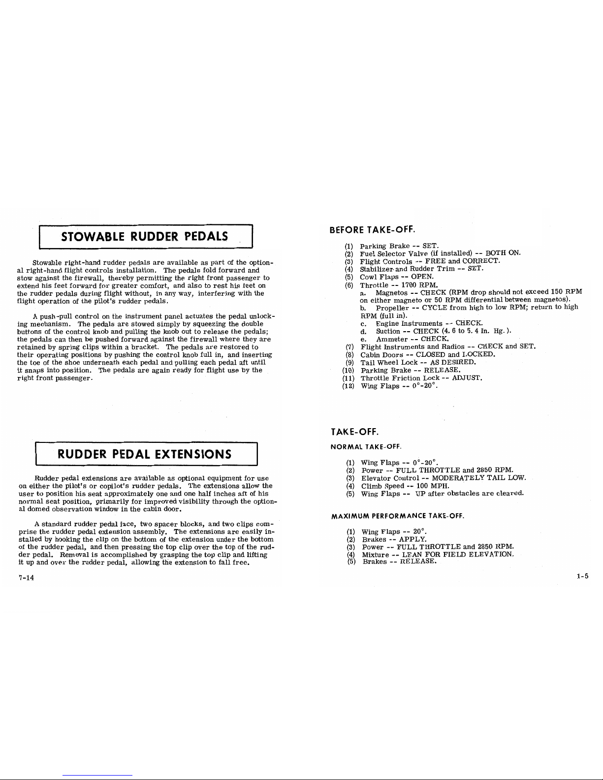
Stowable
right-hand
rudder
pedals
are
available
as
part of the
option-
(3) Flight
Controls
--
FREE
and
CORRECT.
al
right-hand
flight controls installation.
The pedals fold forward and
(4)
Stabilizer
and
Rudder
Trim
--
SET.
stow against
the
firewall,
thereby
permitting the right
front
passenger
to
(5)
Cowl
Flaps
--
OPEN.
extend his feet forward for
greater
comfort,
and also
to
rest
his feet
on (6) Throttle
--
1700 RPM.
the rudder pedals
during
flight
without,
in
any
way,
interfering
with the
a.
Magnetos
--
CHECK
(RPM
drop
should not
exceed
150 RPM
flight
operation
of the pilot's
rudder
pedals.
on
either
magneto
or
50
RPM
differential between
magnetos).
b.
Propeller
--
CYCLE
from
high
to low RPM;
return
to high
A
push-pull
control on
the instrument
panel actuates the pedal
unlock-
RPM
(full in).
ing mechanism. The pedals
are
stowed
simplybysqueezing the double
c. Engine
Instruments
--
CHECK.
buttons of the control knob and pulling
the
knob out to release the pedals;
d.
Suction
--
CHECK
(4. 6to5. 4
In.
Hg.).
the pedals
can
then
be
pushed
forward against the firewall where
they
are
e.
Ammeter
·--
CHECK.
retained
by spring
clips
withinabracket.
The pedals are
restored to
(7)
Flight
Instruments and
Radios
--
CHECK and
SET.
their
operating
positions
by
pushing
the
control
knob
full
in,
and
inserting
(8) Cabin
Doors
--
CLOSED
and
LOCKED.
the toe of the shoe
underneath
each
pedal
and pulling each pedal aft
until
(9) Tail
Wheel
Lock--AS
DESIRED.
it
snaps
into position. The pedals
are
again
ready
for
flight
use by
the
(10)
Parking
Brake
--
RELEASE.
right front passenger.
(11)
Throttle
Friction Lock--ADJUST.
(12)
Wing
Flaps
--
0°-20°.
TAKE-OFF.
I
RUDDER
PEDAL EXTENSIONS
NORMAL
TAKE-OFF.
(1) Wing Flaps
--
0°-20°.
(2)
Power
--
FULL
THROTTLE and 2850 RPM.
Rudder
pedal
extensions are available
as
optional equipment
for
use
(3)
Elevator
Control
--
MODERATELY TAIL
LOW.
on
either the pilot's or copilot's
rudder pedals.
The extensions allow
the
(4)
Climb Speed
--
100
MPH.
user to position
his
seat
approximately
one
and
one half
inches aft of
his
(5)
Wing Flaps
--
UP
after obstacles are
cleared.
normal seat
position,
primarily
for improved
visibility
through the
option-
al
domed observation
window
in the cabin
door.
MAXIMUM
PERFORMANCE
TAKE-OFF.
A
standard
rudder
pedal
face,
two
spacer blocks,
and
two clips
com-
prise
the rudder pedal extension
assembly.
The extensions are
easily
in-
(1) Wing
Flaps
--
20°.
stalled
by hooking the clip
on
the bottom
of
the extension under the bottom (2)
Brakes
--
APPLY.
of
the rudder
pedal, and then
pressing the top
clip over
the top of the
rud-
(3) Power
--
FULL
THROTTLE and
2850
RPM.
der pedal. Itemovalisaccomplished
by grasping the top clip
and
lifting
(4)
Mixture
--
LEAN FOR
FIELD
ELEVATION.
it up and over
the rudder
pedal,
allowing
the extension to
fall free.
(5)
Brakes
--
RELEASE.
7-14
1-5

(6) Elevator
Control
--
MAINTAIN TAIL
LOw·
CARGO PACK
(7) Climb Speed--64 MPH (until all
obstacles
are cleared).
(8)
Wing Flaps
--
UP
after obstacles are
cleared.
FLIGHT OPERATION
WITH
A CARGO
PACK.
ENROUTE
C
LIM
B.
All flight characteristics
for
a cargo pack
equipped
aircraft
are
identical to
an aircraft without
a cargo pack. There
is,
however, a
NORMAL
CLIMB·
slight climb
and cruisà performance differential
between
the
two aircraft.
(1)
Airspeed
-- 110-120
MPH.
The
climb performance
of the
aircraft
equipped with
a cargo pack is
(2)
Power
--
25 INCHES
Hg.
and 2550
RPM•
approximately 40 ft/min
less
than
that
shown in the
MAXIMUM
RATE-OF-
(3)
Mixture
--
LEAN FOR ALTITUDE
AS
NECESSARY'
CLIMB DATA
table for
the
standard airplane.
(4) Cowl
Flaps--AS
REQUIRED.
MAXIMUM
PERFORMANCE
CLIMB
To obtain
the speed performance
for the aircraft
equipped with
a
cargo pack,
the speed
differentials
shown in the table
below should
be
subtracted from the TAS MPH
figures
shown in the
CRUISE
PERFORM-
(1)
Airspeed
--
101
MPH
(sea
level) to 94 MPH
(10,
000 feet).
ANCE tables for the standard
airplane.
Cruising range
is
computed by
(2)
Power
--
FULL
THROTTLE and
2700 RPM.
multiplying the cargo pack
TAS by
the
endurance.
(3)
Mixture
--
LEAN
FOR
ALTITUDE.
(4) Cowl Flaps
--
OPEN.
For
cargo loading,
refer to Section
IV.
CR
UISE.
(1) Power
-- 15-25
INCHES Hg.,
2200-2550
RPM (no
more
than 75/o).
(2) Cowl
Flaps
--
AS
REQUIRED.
(3)
Stabilizer and Rudder
Trim
--
ADJUST.
(4)
Mixture
--
LEAN
for cruise
as
determined
from
your
Cessna
SPEED
DIFFERENTIAL
TABLE
Power
Computer, or in
accordance
with the
Cruise procedures
in
Section
H.
SPEED
DIFFERENTIAL
BHP
MPH
LET-DOWN.
(1) Mixture
--
ENRICHEN
(as
required).
7 5
-7
(2)
Power--AS
DESIRED.
(3) Cowl
Flaps
--
CLOSED.
65
-8
55
-9
BEFORE
LANDING.
45
-9
(1) Mixture
--
RICH.
(2) Fuel Selector Valve (if
installed)
--
BOTH ON.
(3)
Cowl Flaps
--
CLOSED.
Figure
7-4.
9-13
1-6

AMBIENT
FILLING
AMBIENT
FILLING
(4)
Propeller
--
HIGH
RPM.
TEMPERATURE PRESSURE
TEMPERATURE
PRESSURE
(5)
Airspeed
--
85-95
MPH
(flaps
UP).
°F
PSIG
°F
PSIG
(6)
Wing Flaps
--0-
40°
(below.110
MPH).
(7) Airspeed
--
75-85
MPH (flaps
DOWN).
(8)
Stabilizer and Rudder Trim
--
ADJUST FOR
LANDING.
0
1600
50
1825
NOTE
10
1650
60
1875
20 1700 70
1925
The
ability
of
the
aircraft to land three-point is
dependent
30
1725 80
1975
upon
the stabilizer
being
adjusted
for
hands-off
trim
40 1775 90
2000
in
the
glide.
(9)
Tail
Wheel
Lock
--
AS
DESIRED.
pression
of
the
oxygen. Because of this,
merely
filling to 1800
psi
will
not resultina
properly
filled
cylinder. Fill
to
the pressures
indicated
BA
LKED
LANDI
N
G.
in
the table
above
for
the
ambient
temperature.
(1) Power--FULL
THROTTLE
and 2850 RPM.
IMPORTANT
(2)
Wing
Flaps
--
RETRACT
TO
20°.
(3)
Airspeed--80 MPH.
Oil,
grease,
or
other lubricants
in contact
with
oxygen
(4)
Wing
Flaps
--
RETRACT
slowly.
create
a serious fire
hazard, and
such
contact
must be
(5)
Cowl
Flaps
--
OPEN.
avoided
when
handling oxygen equipment.
NORMAL
LANDING.
(1)
Landing
Technique
--
Conventional for
all flap settings.
AFTER LANDING.
(1)
Wing Flaps
--
UP.
(2) Tail
Wheel
Lock
--
UNLOCK.
(3)
Cowl
Flaps
--
OPEN.
(4) Stabilizer
and
Rudder
Trim
--
SET
FOR
TAKE-OFF.
SECURING
AIRCRAFT.
(1)
Parking
Brake
--
SET.
(2)
Radios,
Electrical
Equipment
--
OFF.
(3)
Mixture--IDLE
CUT-OFF.
(4)
Ignition Switch--OFF.
(5)
Master Switch--OFF.
(6) Control Lock
--
INSTALLED.
7-12
1-7

(6) Unplug
the
delivery hose from
the
outlet
coupling
when
discontin-
INSTRUMENT
PANEL
uing use of the
oxygen
system.
This
automatically
stops
the
flow of
oxygen.
(7)
Position
oxygen
supply
control
knob
OFF.
1
2
3
4
5 6
7
8
91011
12 13
14
15
OXYGEN DURATION
CALCULATION.
The
Oxygen Duration
Chart
(figure
7-3)
should be used in
determining
the usable duration (in
hours)
of
the oxygen
supply
in
your airplane.
The
following
procedure
outlines
the method
of finding
the
duration
from the
chart.
(1) Note
the available oxygen
pressure
shown
on
the pressure
gage.
(2) Locate this
pressure
on the scale on
the left side of the
chart,
then go
across the chart
horizontally
to
the
right
until you intersect
the line
representing
the
numberofpersons
making
the
flight. After
intersecting
the
line, drop down
vertically to
the bottom of
the
chart
and read the duration
in hours given
on
the
scale.
(3) As an example of
the above
procedure,
1400
psi of pressure will
safely
sustain the pilot
only
for
nearly 6
hours
and 15 minutes.
The
same
pressure.will
sustain the pilot and
three passengers for
approx-
imately
2 hours
and
30 minutes.
NOTE
The
Oxygen
Duration Chart is
based on
a
standard
con-
figuration
oxygen
system
having
one
orange
color-coded
hose
assembly
for the
pilot
and green
color-coded
hoses
353431 32 31 30 29
28 27
26
25 24
23 22 21 20 19 18 17 16
for the
passengers.
If
orange
color-coded
hoses
are
provided
for pilot and
passengers,
it will be
necessary
1.
FlightInstrumentGroup
22. MixtureContro1Knob
tO
COmpute
new oxygen
duration figures due
to
the
greater
2.
Aircraft
Registration Number
23. Autopilot Control Unit (Opt.)
3.
Localizer
Reversed
Indicator
24.
Propeller Control Knob
COBSumption of
oxygen with
these
hoses.
This is
accom-
Lights (Opt.)
25. Throttle (With
Friction
Lock)
liShed
by
computing the
total
duration available to
the
4.
Marker Beacon
Indicator 13. Over-Voltage
Warning
Light
26. Microphone (Opt.)
Lights and
Switch (Opt.) 14. Cylinder
Head Temperature,
27. Circuit Breakers pilot
only
(from
PILOT
ONLY line
on
chart),
then
di-
5.
Transponder (Opt.) Oil
Temperature and Oil
28. Static Pressure Alternate
viding
this
duration by
the
number
of persons
(pilot
and
6.
Magnetic
Compass Pressure Gages Source
Va1ye (Opt.)
7.
Radio
Selector Switches (Opt.) 15. Optiona1Radio
Space
29. Electrical
Switches
passengers)
using
oxygen.
8.
Radios (Opt.)
16.
Map
Compartment
30.
Parking
Brake
HandÏe
9. Manifold Pressure/Fuel Flow 17. Stowable Rudder
Pedal
31.
Ignition
Switch
Indicator
Control
Space
(Opt.)
32.
Auxiliary
Fuel Pump Switch
10. Tachometer 18. Cowl Flap Handle
33. Master Switch
11.
Economy
Mixture Indicator (Opt.)
19. Cabin
Heat Control
34.
Headphone and
Auxiliary
OX
YGENSY STEMSERV ICI
N G.
12.
Fuel
Quantity
Indicators
and 20.
Cigar
Lighter .
Microphone Jacks
Ammeter 21. Cabin Air ControI
35. Primer
The oxygen
cylinder,
when fully
charged,
contains
approximately
48 cubic feet of
oxygen,
underapressure of 1800
psi at
70°F.
Filling
pressures
will
vary,
however,
due
to
the ambient
temperature in
the
Figure
2-1·
filling
area, and
because
of
the temperature
rise resulting
from
com-
1-8
7-11

or
alcohol
will
usually
necessitate
the use of oxygen
at less than
10,
000
feet.
NOTE
For safety reasons,
no smoking
should
be
allowed
in
the
airbraft
while
oxygen is being
used.
DESCRIPTION
AND
OPERATING
DETAILS
When ready to use
the
oxygen
system,
proceed
as
follows:
The
following paragraphs
describe the
systems
and equipment whose
(1)
Select mask
and
hose.
.
function
and operation
is not
obvíous
when
sitting
in
the aircraft
.
This
NOTE
section
also covers
in somewhat greater detail
some
of the
items listed
in
Checklist
form
in Section
I
that require
further
explanation.
The hose provided for
the
pilot is
ofahigher flow rate
than those for the passengers; it is
color-coded
with
an
orange
band adjacent
to the
plug-in
fitting. The
passen-
ger hoses are
color-coded
withagreen
band. If
the
air- FUEL
SYSTEMS.
craft
ownýr
prefers, he
may
provide higher
flow hoses
for all passengers. In
any case, it is
recommended that
The
aircraft
contains, as
standard
equipment, an
"ON-OFF"
fuel
the
pilot
asethe larger
capacity
hose. The pilot's mask
shutoff
valve system.
An optional selector
valve system which
provides
is
equipped
with a
microphone to facilitate use of the
fuel tank
selection
capability is also
available. Details
of both systems
radio
white
using
oxygen.
An
adapter
cord
is furnished
are
discussed
in the
following
paragraphs.
Optional
long range
fuel
tanks
with the
niicrophone-equipped
mask to mate
the
mask
are
also
available.
microphone
lead
to
the AUX
MIKE JACK located on
the
left
side of
the
instrument panel.
To connect
the
"ON-OFF"
FUEL
SYSTEM.
oxygen mask
microphone,
connect
the
mask
lead
to the
adapter
cord
and
plug the cord
into the AUX
MIKE
Fuel
is
supplied
to
the
engine from
two
tanks,
one
in each
wing. The
JACK. (If
an optional
microphone-headset
combination
total usable
fuel,
for
all
flight
conditions, is 62
gallons.
has been in
use,
the microphone lead
from
this
equip-
ment is
already
plugged
into the
AUX MIKE JACK. It
Fuel
from each
wing
tank
flows by
gravity
through
a
fuel
accumulator
will be
necessary
to disconnect
this lead from the AUX
tank, shutoff
valve,
fuel
strainer,
by-pass
in
the
electric
auxiliary
fuel
MIKE
JACK so
that
the adapter cord from
the oxygen
pump
(when it is
not
operating)
and
engine-driven
fuel
pump to
the
cylind-
mask
microphone canbeplugged
into the jack.)
A
switch
ers via
a
fuel
control
unit
and manifold.
Vapor
and
excess fuel
from the
is
incorporated
on the left hand control
wheel to
operate
engine-driven
fuel
pump and
fuel
control
unit are
returned
to the
main
the microphone.
fuel
tanks
by
way
of
the fuel
accumulator
tank.
(2) Attach mask
to face and
adjust metallic nose
strap
for
snug
mask
To
provide
fuel
flow
to the
engine, squeeze
together the
double
buttons
fit.
of
the
fuel
shutoff
valve control knob
(located
on the
floor
console),
re-
(3) Select
oxygen outlet located
nearest
to the
seat
you
are
occupy-
leasing
the
lock, and
push the knob full
in. Fuel
will flow
from
both
wing
ing, and
plug
delivery
hose
into
it. When the oxygen
supply is
turned
fuel
tanks
simultaneously.
on, oxygen
will flow
continuously
at
the proper
rate of flow for
any
NOTE
altitude without
any
manual
adjustments.
(4)
Position
oxygen
supply
control
lmob
ON.
With full
fuel, the
tanks
may
not
drain
evenly because
(5) Check the
flow indicator in the
face
mask hose. Oxygen is
flow-
fuel
may be
sloshed into
the interconnect
vent
line,
ing if the
indicator is being forced
toward the mask.
preventing
absolutely equal
vent
pressures
in each
7-10
2-1

FUEL SYSTEM
SCHEMATIC
OXYGEN DURATION
CHART
"Oll-OFF"
FUEL$YSTEM
(48
cuBic FEET CAPACITY)
VENTED FILLER
CAPS
il emninilininninnuiliniu sii
1000
VENT
VENT
LFFT FLEl
TANK
RIGHT
¥UEl
TANK
FUEL
ACCUMULATOR
TANK
TO ENSURE MAXIMUM FUEL CAPACITY
DURING REFUEl ING, THE TANKS
SHOUlD
BE
RE-TOPPED
IMMEDIATELY
AFTER
INITIAL
FILLING TO COMPENSATE FOR
- -
CROSS-FEEDING.
IÏuEL-OFF
wa¯
VALVE
FUEL
SHUT-OFF
KNOB
FUEL
-----
ENGINE
STRAINER
ENGINE
FRIMER
CHECK VALVE
AUXILIARY
(FUEL
RETURN)
FUEL PUMP
AUXILIARY
FUEL
PUMP SWITCH
400
ENGINE
01||
lil
FUEL
PUMP
THROTTLE
c2TROL
----
O
UNIT
MIXTURE
O
I
2
3
4 5 6
7 8
9
ELF
OXYGEN
DURATION
-
(HOURS)
I
¯¯¯
-CODE-----
FUEL SUPPLY
INU
TION
0001Il000EXCESSFUELAND
NOTE:
This chart
is based on
a pilot with an arange
color.coded
oxygen
NOZZLE
VAPORRETURN
line fitting
and
passengers with green
color-coded
line fittings.
FUEL FLOW
VENT
INDICATV)R
Figure
2-2.
Figure
7-3.
2-2
7-9
 Loading...