

Cessna 310 1975 Owner's Manual
'--"
'-'
~
'-'
Cessna®
___,·
'--"
MORE
PEOPLE
BUY
AND
'--'
FLY
CESSNA
AIRPLANES
~
THAN
ANY
OTHER
MAKE
'---"""
'--'
'--'
'--'
1975
WORLD'S
LARGEST
PRO-
DUCER
OF
GENERAL
AVIATION
AIRCRAFT
SINCE
1956
MODEL
310
OWNER'S
MANUAL
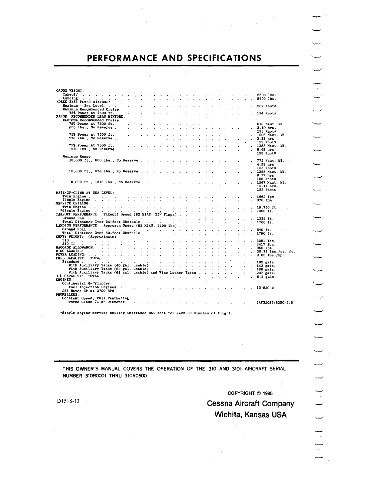
PERFORMANCE
AND
SPECIFICATIONS
GROSS
WEIGHT:
T&keoff
• • • • , •
La.nding . . . . .
SPEED BEST
POWER
MIXTURE:
Maximum -
Sea
Level
. ,
Maximum
Recommended
Cruise
75%
Power
at
7500
ft.
.
RANGE,
RECOMMENDED
LEAN
MIXTURE:
Maximum Recommended
Cruise
75%
Power
at
7500
ft.
600
lbs.
, No
Reserve
,
75'.£
Pow'er
at
7500
ft.
978
lbs.,
No
Reserve
,
75%
Power
at
7500
ft.
1218
lbs. , No
Reserve
Maximum Range
10,
000
ft.
,
600
lbs. , No
Reserve
10,000
ft.,
978
lbs.,
No
Reserve
10,000
ft.,
1218
lbs.,
No
Reserve
RATE-OF-CLHfB
AT
SEA
LEVEL:
Twin
Engine
. .
Single
Engine
.
SERVICE
CEILING:
Twin
Engine
.
TA~5;;i;E~~~~~cE:
·Takeoff
Spe~d
(s2
· KIAs, '150
Fiap~)
Ground
Run
. . . . . . , . .
Total
Distance
Over
50-foot
Obstacle
, .
LANDING
PERFORMANCE:
Approach
Speed
(93
KIAS,
5400
lbs)
Ground
Roll
, . . . , • . . .
Total
Distance
Over
50-foot
Obstacle
EMPTY
WEIGHT:
(Approximate}
310
310
II
. ,
BAGGAGE
ALLOWANCE:
WING
LOADING:
POWER
LOADING:
FUEL CAPACITY: TOTAL
Sta:~~~dA~xiiia~y
Tanks
(40°gai.
~sable)
With
Auxiliary
Tanks
(63
gal.
usable)
. . . . , . .
With
Auxiliary
Tanks
(63
gal.
usable)
and
Wing
Locker
Tanks
OIL
CAPACITY: TOTAL
ENGINES:
Continental
6-Cylinder
Fuel
Inject
ion
Engines
285
Rated
HP
at
2700
RPM
PROPELLERS :
Constant
Speed,
Full
Feathering
Three
Blade
76.
5"
Diameter
,
5500
lbs.
5400
lbs,
207
Knots
194
Knots
616
Naut.
Mi.
3.19
hrs.
193
Knots
1006
Naut.
Mi.
5.21
hrs.
193
Knots
1253
Na.ut.
Mi.
6.49
hrs.
193
Knots
772
Naut.
Mi.
4.98
hrs.
155
Knots
1258
Naut.
Mi.
8.12
hrs.
155
Knots
1567
Naut.
Mi,
10.11
hrs.
155
Knots
1662
fpm.
370
fpm.
19,750
ft.
7400
ft.
1335
ft.
1700
ft.
640
ft.
1790
ft.
3251
lbs.
3417
lbs.
950
lbs.
30.73
lbs./sq.
ft.
9.65
lbs.
/hp.
102
gals.
143
gals.
166
gals.
207
gals.
6.5
gals.
I0-520-M
3AF32C87
/82NC-5.
5
•Single
engine
service
ceiling
increases
300
feet
for
each
30
minutes
of
flight.
THIS OWNER'S MANUAL
COVERS
THE
OPERATION
OF
THE
310
AND
31011
AIRCRAFT
SERIAL
NUMBER
310R0001
THRU
310R0500
01518-13
COPYRIGHT ©
1985
Cessna Aircraft Company
Wichita, Kansas
USA
CONGRATULATIONS
...............
..
Welcome to
the
ranks
of
Cessna
owners!
Your
Cessna
has
been
designed
and
con-
structed
to
give
you
the
most
in
performance , economy,
and
comfort .
It
is
our
desire
that
you
will find
flying
it,
either
for
business
or
pleasure, a pleasant
and
profitable
experience.
This
Owner's
Manual
has
been
prepared
as a guide
to
help
you
get
the
most
pleas-
ure
and.utility
from
your
aircraft.
It
contains
information
about
your
Cessna's
equip-
ment,
operating
procedures,
and
performance;
and
suggestions
for
its
servicing
and
care.
We
urge
you
to
read
it
from
cover
to
cover,
and
to
refer
to it
frequently.
Our
interest
in
your
flying
pleasure
has
not
ceased
with
your
purchase
of a
Cessna.
Worldwide
the
Cessna
Dealer
Organization
backed
by
the
Cessna
Service
Department
stands
ready
to
serve
you.
The
following
services
are
offered
by
most
Cessna
Dealers:
THE
CESSNA WARRANTY --it
is
designed
to
provide
you
with
the
most
comprehen-
sive
coverage
possible:
a.
No
exclusions
b.
Coverage
includes
parts
and
labor
c.
Available
at
Cessna
Dealers
worldwide
d.
Best
in
the
industry
Specific
benefits
and
provisions
of
warranty
plus
other
important
benefits
for
you
are
contained
in
your
Customer
Care
Program
book
supplied
with
your
aircraft.
Warranty
service
is
available
to
you
at
any
authorized
Cessna
Dealer
throughout
the
world
upon
presentation
of
your
Customer
Care
Card
which
establishes
your
eligibility
under
the
warranty.
FACTORY TRAINED PERSONNEL
to
provide
you
with
courteous
expert
service.
FACTORY APPROVED SERVICE EQUIPMENT
to
provide
you
with
the
most
efficient
and
accurate
workmanship
possible.
A STOCK
OF
GENUINE CESSNA SERVICE PARTS
on
hand
when
you
need
them.
THE LATEST AUTHORITATIVE INFORMATION
FOR
SERVICING CESSNA AIRCRAFT,
since
Cessna
Dealers
have
all
of
the
Service
Manuals
and
Parts
Catalogs,
kept
cur-
rent
by
Service
Letters
and
Service
News
Letters,
published
by
Cessna
Aircraft
Company.
We
urge
all
Cessna
owners
to
use
the
Cessna
Dealer
Organization
to
the
fullest.
A
current
Cessna
Dealer
Directory
accompanies
your
new
aircraft.
The
Directory
is
revised
frequently,
and a current
copy
can
be
obtained
from
your
Cessna
Dealer.
Make
your
Directory
one
of
your
cross-country
flight
planning
aids; a warm
welcome
awaits
you
at
every
Cessna
Dealer.
i
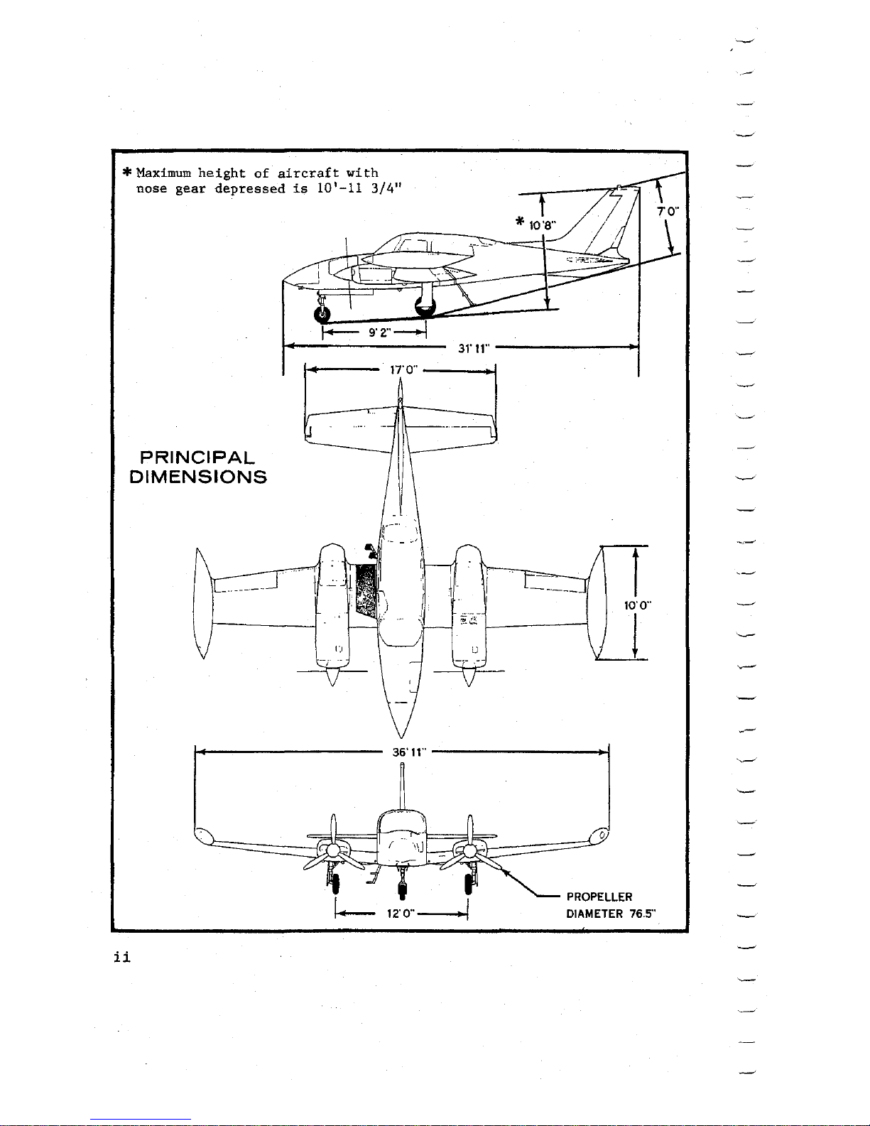
*Maximum
height
of
aircraft
with
nose
gear
depressed
is
10'-11
3/4"
31'
11''
---------..i
17'0"
----.!
PRINCIPAL
DIMENSIONS
ii
36'11"----------i
DIAMETER 76.5"
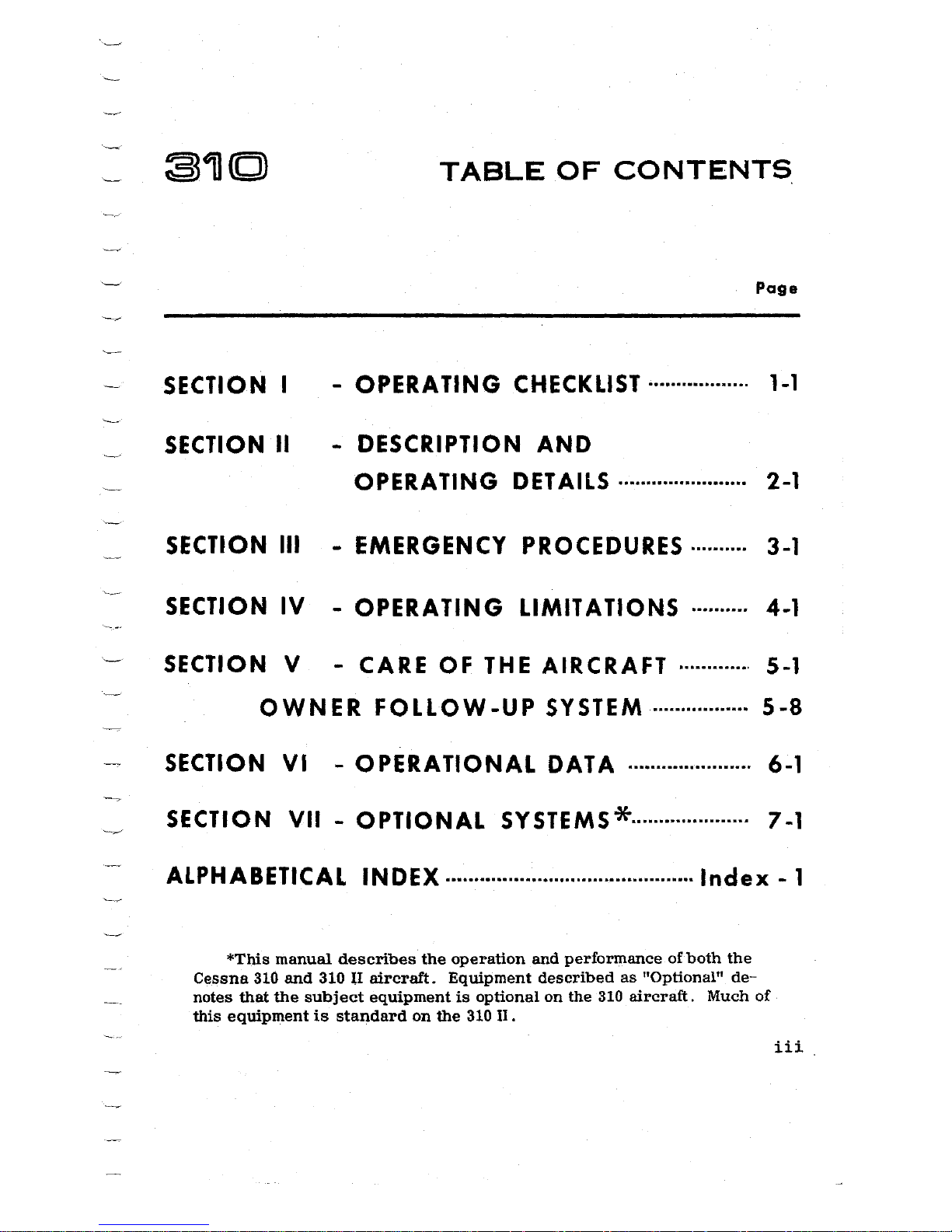
TABLE
OF
CONTENTS.
Page
SECTION I
- OPERATING CHECKLIST··················
1-1
SECTION
II
- DESCRIPTION
AND
OPERATING
DETAILS
.......................
2-1
SECTION
Ill
-
EMERGENCY
PROCEDURES
..........
3-1
SECTION
IV
- OPERATING LIMITATIONS ..........
4-1
SECTION
V - CARE OF
THE
AIRCRAFT
.............
5-1
OWNER
FOLLOW-UP
SYSTEM
.................
5-8
SECTION
VI
- OPERATIONAL
DATA
...................... 6-1
SECTION
VII
- OPTIONAL SYSTEMS* ..................... 7-1
ALPHABETICAL
INDEX
............................................
Index
- 1
*This
manual
describes
the
operation
and
performance
of
both
the
Cessna
310
and
310
lI
aircraft.
Equipment
described
as
"Optional"
de-
notes
that
the
subject
equipment
is
optional
on
the
310
aircraft.
Much
of
this
equipment
is
standard
on
the
310
II.
iii.
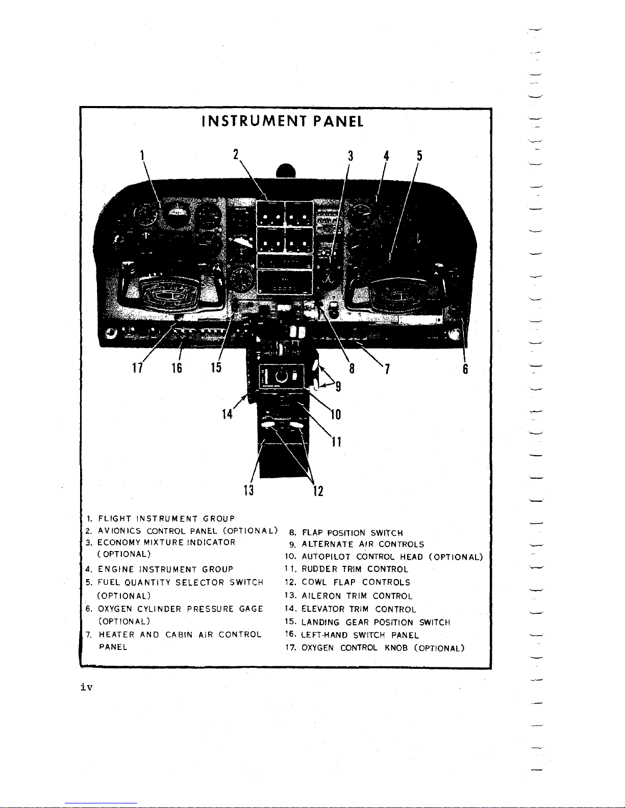
INSTRUMENT
PANEL
1.
FLIGHT
INSTRUMENT
GROUP
2.
AVIONICS
CONTROL PANEL
(OPTIONAL)
3.
ECONOMY
MIXTURE
INDICATOR
(OPTIONAL)
4.
ENGINE
INSTRUMENT
GROUP
5.
FUEL
QUANTITY
SELECTOR
SWITCH
(OPTIONAL)
6.
OXYGEN
CYLINDER
PRESSURE GAGE
(OPTIONAL)
7.
HEATER
AND
CABIN
AIR
CONTROL
PANEL
iv
12
8. FLAP POSITION SWITCH
9.
ALTERNATE
AIR
CONTROLS
10. AUTOPILOT CONTROL HEAD
(OPTIONAL)
11.
RUDDER TRIM CONTROL
12. COWL
FLAP
CONTROLS
13.
AILERON
TRIM CONTROL
14.
ELEVATOR TRIM CONTROL
15. LANDING GEAR POSITION SWITCH
16. LEFT-HAND SWITCH PANEL
17.
OXYGEN
CONTROL
KNOB
(OPTIONAL)
~~©lTD®~
0
OPERATING
CHECKLIST
One
of
the
first
steps
in
obtaining
the
utmost
perfor-
mance,
service,
and
flying
enjoyment
from
your
Cessna
is
to
familiarize
yourself
with
your
aircraft's
equipment,
systems,
and
controls.
This
can
best
be
done
by
reviewing
this
equip-
ment
while
sitting
in
the
aircraft.
Those
items
whose
func-
tion
and
operation
are
not
obvious
are
covered
in
Section
II.
Section
I
lists,
in
Pilot's
Checklist
form,
the
steps
necessary
to
operate
your
aircraft
efficiently
and
safely.
It
covers
briefly
all
the
points
that
you
should
know
con-
cerning
the
information
you
need
for a typical
flight.
The
flight
and
operational
characteristics
of
your
aircraft
are
normal
in
all
respects.
All
controls
respond
in
the
normal
way
within
the
entire
range
of
operation.
MAKE A PREFLIGHT
INSPECTION
IN
ACCORDANCE
WITH
FIGURE
1-1.
BEFORE
STARTING
THE
ENGINES
(1)
Preflight
Inspection
-
COMPLETE.
(2)
Control
Lock(s)
-
REMOVE.
(3)
Seats,
Seat
Belts
and
Shoulder
Harness -ADJUST
and
SECURE.
(4)
Brakes
-
TEST
and
SET.
(5)
Landing
Gear
Switch -DOWN.
(6)
Emergency
Alternator
Field
Switch
- OFF.
(7)
Emergency
Avionics
Power
Switch -OFF.
(8)
Avionics
Master
Switch -OFF.
(9)
Circuit
Breakers
- IN.
(10)
All
Switches
- OFF.
(11)
Battery
and
Alternators
-
ON.
1-1
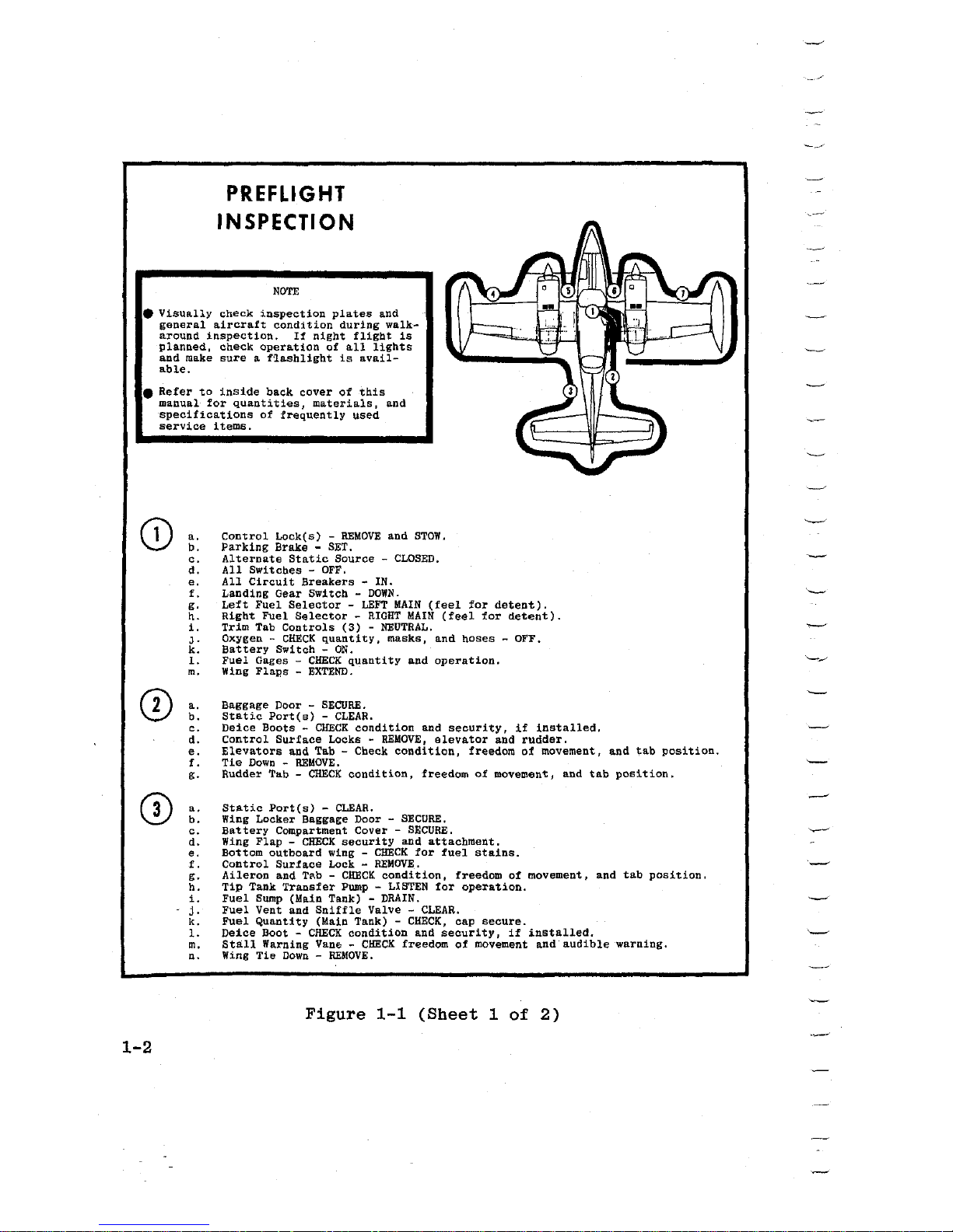
PREFLIGHT
INSPECTION
NOTE
e
Visually
check
inspection
plates
and
general
aircraft
condition
during
walk-
around
inspection.
If
night
flight
is
planned,
check
operation
of
all
lights
and
make
sure a flashlight
is
avail-
able.
e
Refer
to
inside
back
cover
of
this
manual
for
quantities,
materials,
and
specifications
of
frequently
used
service
items.
CD
a.
b.
c.
d.
e.
f.
g.
h.
i.
J.
k.
l.
m.
0
a.
b.
c.
d.
e.
f.
g.
0
a.
b.
c.
d.
e.
f.
g.
h.
i.
j.
k.
l.
m.
n.
1-2
Control
Lock(s) -REMOVE
and
STOW.
Parking
Brake
- SET.
Alternate
Static
Source -CLOSED.
All
Switches
- OFF.
All
Circuit
Breakers
- IN.
Landing
Gear
Switch -DOWN.
Left
Fuel
Selector -LEFT
MAIN
(feel
for
detent).
Right
Fuel
Selector -RIGHT
MAIN
(feel
for
detent).
Trim
Tab
Controls
(3) -NEUTRAL.
Oxygen -CHECK
quantity,
masks,
and
hoses -OFF.
Battery
Switch -ON.
Fuel
Gages -CHECK
quantity
and
operation.
Wing Fla11s -
EXTEND.
Baggage
Door -SECURE.
Static
Port(s) -CLEAR.
Deice
Boots -CHECK
condition
and
security,
if
installed.
Control
Surface
Locks -REMOVE,
elevator
and
rudder.
Elevators
and Tab - Check
condition,
freedom
of
movement, and
tab
position.
Tie
Down -REMOVE.
Rudder Tab -
CHECK
condition,
freedom
of
movement, and
tab
position.
Static
Port(s) -CLEAR.
Wing
Locker
Baggage
Door
- SECURE.
Battery
Compartment
Cover -SECURE.
Wing
Flap -CHECK
security
and
attachment.
Bottom
outboard
wing -CHECK
for
fuel
stains.
Control
Surface
Lock -
REMOVE.
Aileron
and
T~.b
-
CHECK
condition,
freedom
of
movement, and
tab
position.
Tip
Tank
Transfer
Pump - LISTEN
for
operation.
Fuel
Sump
(Main
Tank)
- DRAIN.
Fuel
Vent
and
Sniffle
Valve -CLEAR.
Fuel
Quantity
(Main
Tank) -CHECK,
cap
secure.
Deice
Boot -CHECK
condition
and
security,
if
installed.
Stall
Warning Vane -
CHECK
freedom
of
movement and
audible
warning.
Wing
Tie
Down -REMOVE.
Figure
1-1
(Sheet
1
of
2)
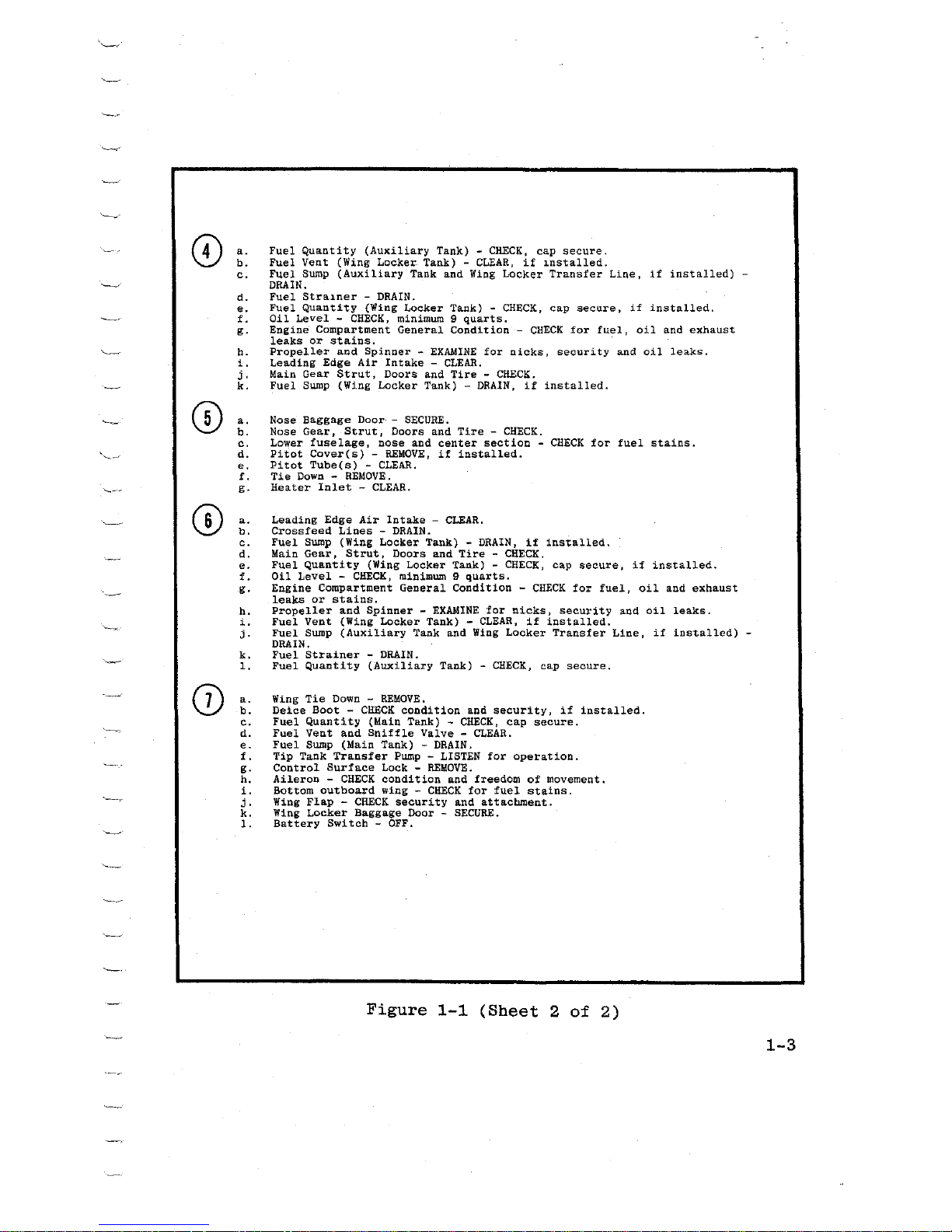
©
a.
b.
c.
d.
e.
f.
g.
h.
i.
j'
k.
®
a.
b.
c.
~~
d.
e.
f.
g.
©
a.
b.
c.
d.
e.
f.
g.
h.
i.
j.
k.
l,
(J)
a.
b.
c.
d.
e.
f.
g.
h.
i.
j.
k.
l.
Fuel
Quantity
(Au><iliary
Tank) -CH.ECK,
cap
secure.
Fuel
Vent
(Wing
Locker
Tank) -CLEAR,
if
installed.
Fuel
Sump
(Auxiliary
Tank
and
Wing
Locker
Transfer
Line,
if
installed)
-
DRAIN.
Fuel
Strainer
- DRAIN.
Fuel
Quantity
(Wing
Locker
Tank)
- CHECK,
cap
secure,
if
installed.
Oil
Level -CHECK,
minimum 9
quarts.
Engine
Compartment
General
Condition -CHECK
for
fuel,
oil
and
exhaust
leaks
or
stains.
Propeller
and
Spinner -EXAMINE
for
nicks,
security
and
oil
leaks.
Leading
Edge
Air
Intake -CLEAR.
Main
Gear
Strut,
Doors
and
Tire -CHECK.
Fuel
Sump
(Wing
Locker
Tank)
- DRAIN,
if
installed.
Nose
Baggage
Door
- SECURE.
Nose
Gear,
Strut,
Doors
and
Tire -CHECK.
Lower
fuselage,
nose
and
center
section -CHECK
for
fuel
stains.
Pitot
Cover(s) -REMOVE,
if
installed.
Pitot
Tube(s) -CLEAR.
Tie
Down -
REMOVE
.
Heater
Inlet
- CLEAR.
Leading
Edge
Air
Intake -CLEAR.
Cross
feed
Lines -DRAIN.
Fuel
Sump
(Wing
Locker
Tank)
- DRAIN,
if
installed,
Maio
Gea.r,
Strut 1 Doors
and
Tire -CHECK,
Fuel
Quantity
(Wing
Locker
Tank) -CHECK,
cap
secure,
if
installed.
Oil
Level -CHECK,
minimum 9
quarts.
Engine
Compartment
General
Condition -CHECK
for
fuel,
oil
and
exhaust
leaks
or
stains.
Propeller
and
Spinner -EXAMINE
for
nicks,
secu:ri
ty
and
oil
leaks.
Fuel
Vent
(Wing
Locker
Tank) -CLEAR,
if
installed.
Fuel
Swnp
(Auxiliary
Tank
and
Wing
Locker
Transfer
Line,
if
installed)
-
DRAIN.
Fuel
Strainer
- DRAIN.
Fuel
Quantity
(Auxiliary
Tank) -CHECKJ
cap
secure.
Wing
Tie
Down -
REMOVE.
Deice
Boot -CHECK
condition
and
security,
if
installed.
Fuel
Quantity
(Main
Tank) -CHECK,
cap
secure.
Fuel
Vent
and
Sniffle
Valve -CLEAR.
Fuel
Sump
(Main
Tank)
- DRAIN.
Tip
Tank
Transfer
Pump - LISTEN
for
operation.
Control
Surface
Lock -REMOVE.
Aileron -CHECK
condition
and
freedom
of
movement.
Bottom
outboard
wing -CHECK
for
fuel
stains.
Wing
Flap -CHECK
security
and
attachment.
Wing
Locker
Baggage
Door
- SECURE.
Battery
Switch
- OFF.
Figure
1-1
(Sheet
2
of
2)
1-3
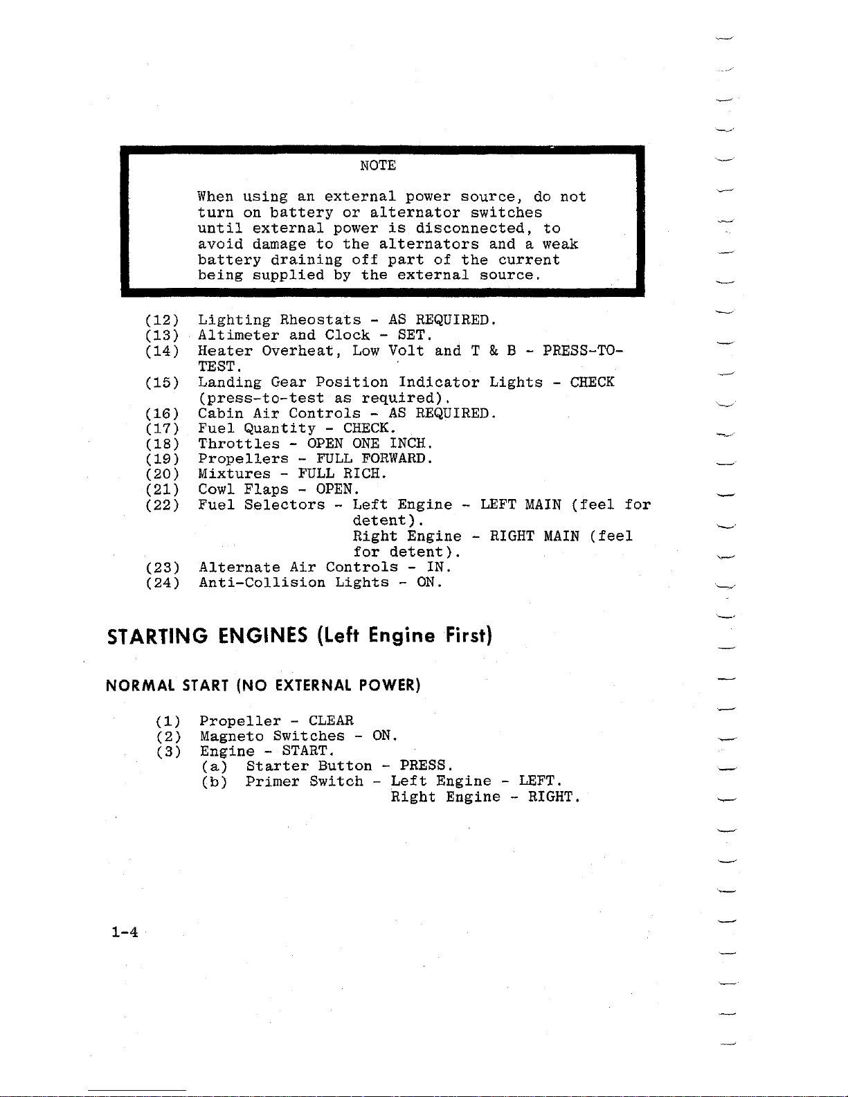
NOTE
When
using
an
external
power
source,
do
not
turn
on
battery
or
alternator
switches
until
external
power
is
disconnected,
to
avoid
damage
to
the
alternators
and a weak
battery
draining
off
part
of
the
current
being
supplied
by
the
external
source.
(12)
Lighting
Rheostats
-
AS
REQUIRED.
(13)
Altimeter
and
Clock
- SET.
(14)
Heater
Overheat,
Low
Volt
and T & B - PRESS-TO-
TEST.
(15)
(16)
(17)
(18)
(19)
(20)
(21)
(22)
(23)
(24)
Landing
Gear
Position
Indicator
Lights
-
CHECK
(press-to-test
as
required).
Cabin
Air
Controls
-
AS
REQUIRED.
Fuel
Quantity
-
CHECK.
Throttles
-
OPEN
ONE
INCH.
Propellers
-
FULL
FORWARD.
Mixtures
-
FULL
RICH.
Cowl
Flaps -OPEN.
Fuel
Selectors
-
Left
Engine -LEFT
MAIN
(feel
for
detent).
Right
Engine -RIGHT
MAIN
(feel
for
detent).
Alternate
Air
Controls
- IN.
Anti-Collision
Lights
-
ON.
STARTING
ENGINES
(Left
Engine
First}
NORMAL
ST
ART
(NO
EXTERNAL
POWER)
1-4
(1)
Propeller
-
CLEAR
(2)
Magneto
Switches
-
ON.
(3)
Engine -START.
(a)
Starter
Button
- PRESS.
(b)
Primer
Switch -Left
Engine -LEFT.
Right
Engine -RIGHT.
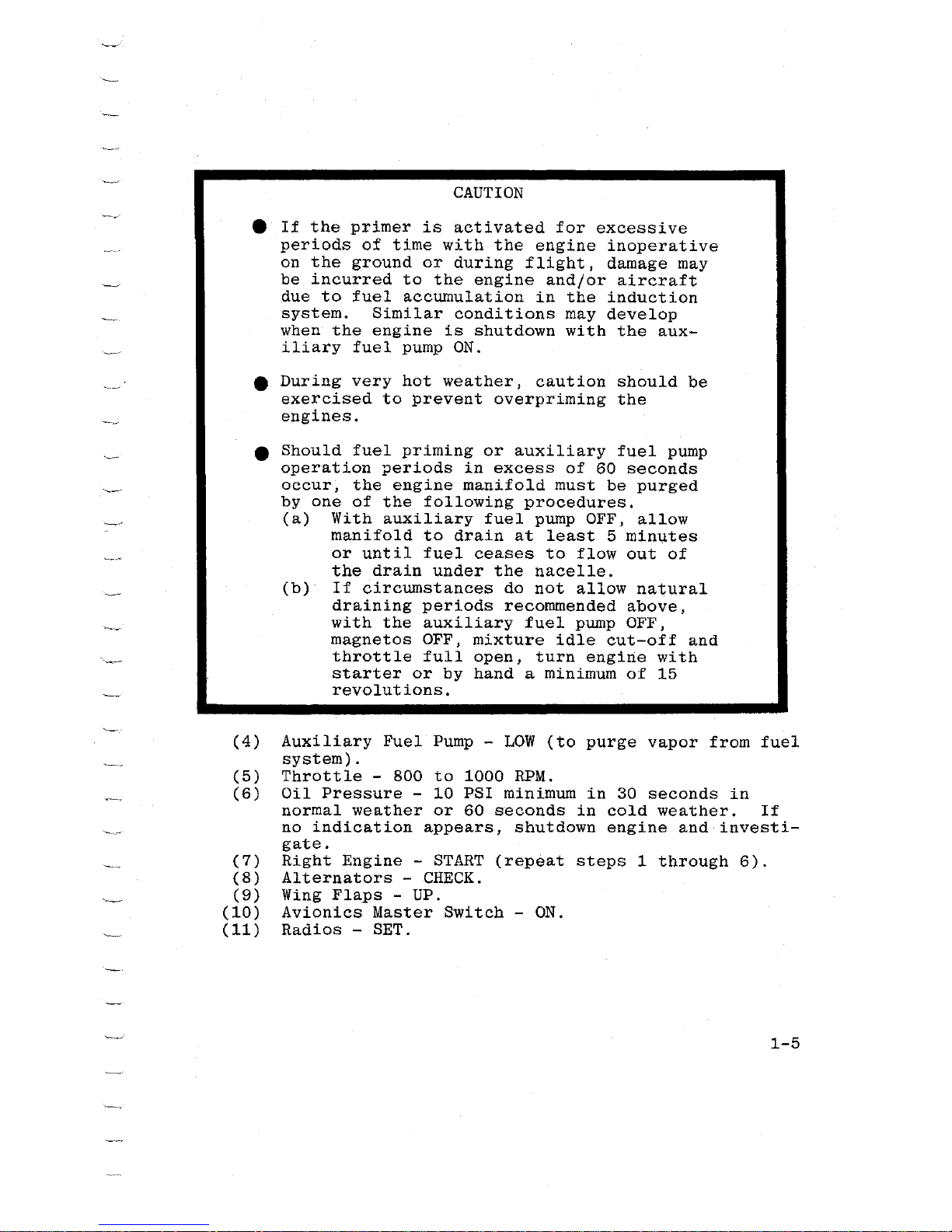
CAUTION
e
If
the
primer
is
activated
for
excessive
periods
of
time
with
the
engine
inoperative
on
the
ground
or
during
flight,
damage may
be
incurred
to
the
engine
and/or
aircraft
due
to
fuel
accumulation
in
the
induction
system.
Similar
conditions
may
develop
when
the
engine
is
shutdown
with
the
aux-
iliary
fuel
pump
ON.
e
During
very
hot
weather,
caution
should
be
exercised
to
prevent
overpriming
the
engines.
e
Should
fuel
priming
or
auxiliary
fuel
pump
operation
periods
in
excess
of
60
seconds
occur,
the
engine
manifold
must
be
purged
by
one
of
the
following
procedures.
(a)
With
auxiliary
fuel
pump OFF,
allow
manifold
to
drain
at
least
5
minutes
or
until
fuel
ceases
to
flow
out
of
the
drain
under
the
nacelle.
(b)
If
circumstances
do
not
allow
natural
draining
periods
recommended
above,
with
the
auxiliary
fuel
pump OFF,
magnetos
OFF,
mixture
idle
cut-off
and
throttle
full
open,
turn
engine
with
starter
or
by
hand
a minimum
of
15
revolutions.
(4)
Auxiliary
Fuel
Pump -LOW
(to
purge
vapor
from
fuel
system).
(5)
Throttle
- 800
to
1000
RPM.
(6)
Oil
Pressure
-
10
PSI
minimum
in
30
seconds
in
normal
weather
or
60
seconds
in
cold
weather.
If
no
indication
appears,
shutdown
engine
and
investi-
gate.
(7)
Right
Engine -START
(repeat
steps
1
through
6).
(8)
Alternators
-
CHECK.
(9)
Wing
Flaps
- UP.
(10)
Avionics
Master
Switch -ON.
(11)
Radios
- SET.
1-5
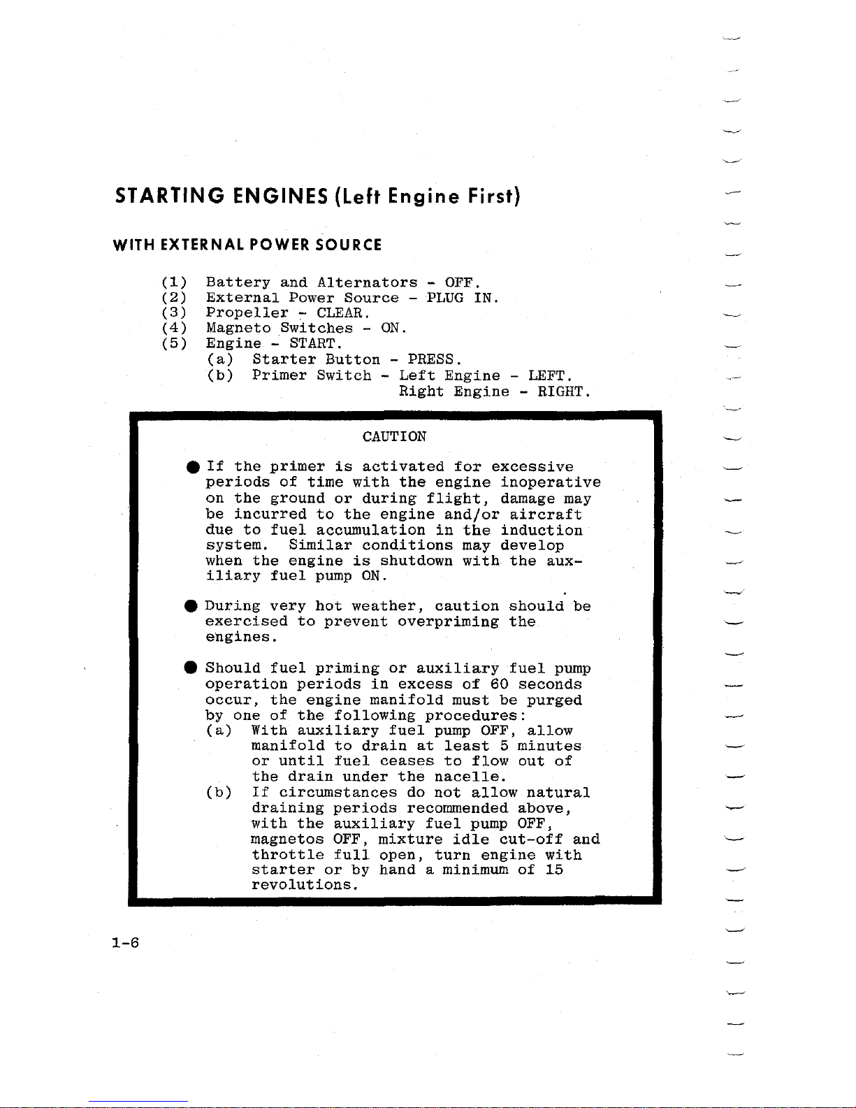
STARTING ENGINES {Left Engine First)
WITH EXTERNAL POWER SOURCE
1-6
(1)
Battery
and
Alternators
- OFF.
(2)
External
Power
Source -PLUG
IN.
(3)
Propeller
-
CLEAR.
(4)
Magneto
Switches
-
ON.
(5)
Engine -START.
(a)
Starter
Button
- PRESS.
(b)
Primer
Switch -Left
Engine
- LEFT.
Right
Engine -RIGHT.
CAUTION
e
If
the
primer
is
activated
for
excessive
periods
of
time
with
the
engine
inoperative
on
the
ground
or
during
flight,
damage
may
be
incurred
to
the
engine
and/or
aircraft
due
to
fuel
accumulation
in
the
induction
system.
Similar
conditions
may
develop
when
the
engine
is
shutdown
with
the
aux-
iliary
fuel
pump
ON.
e
During
very
hot
weather,
caution
should
be
exercised
to
prevent
overpriming
the
engines.
e
Should
fuel
priming
or
auxiliary
fuel
pump
operation
periods
in
excess
of
60
seconds
occur,
the
engine
manifold
must
be
purged
by
one
of
the
following
procedures:
(a)
With
auxiliary
fuel
pump
OFF,
allow
manifold
to
drain
at
least
5
minutes
or
until
fuel
ceases
to
flow
out
of
the
drain
under
the
nacelle.
(b)
If
circumstances
do
not
allow
natural
draining
periods
recommended
above,
with
the
auxiliary
fuel
pump OFF,
magnetos
OFF,
mixture
idle
cut-off
and
throttle
full
open,
turn
engine
with
starter
or
by
hand
a minimum
of
15
revolutions.

(6)
Auxiliary
Fuel
Pwnp -
LOW
(to
purge
vapor
from
fuel
system).
(7)
Throttle
-
800
to
1000
RPM.
{8)
Oil
Pressure
-
10
PSI
minimum
in
30
seconds
in
normal
weather
or
60
seconds
in
cold
weather.
If
no
indication
appears,
shutdown
engine
and
investi-
gate.
(9)
Right
Engine -START
(repeat
steps
3
through
8).
(10)
External
Power
Source -UNPLUG.
(11)
Battery
and
Alternators
-
ON.
(12)
Alternators
-
CHECK.
(13)
Wing
Flaps
- UP.
(14)
Avionics
Master
Switch -ON.
(15)
Radios
- SET.
BEFORE
TAKEOFF
(1)
Brakes
- SET.
(2)
Engine
Runup:
(a)
Throttles
-
1700
RPM.
(b)
Alternators
-
CHECK.
(c)
Magnetos -CHECK
(150
RPM
maximum
drop
with
a
maximum
differential
of
50
RPM).
(d)
Propellers
-
CHECK
feathering
to
1200
RPM;
return
to
high
RPM
(full
forward
position).
(e)
Engine
Instruments
-
CHECK
green
arc.
(f)
Vacuum
System -CHECK
(4.75
to
5.25
inches
Hg.).
(g)
Throttles
-
1000
RPM.
NOTE
It
is
important
that
the
engine
oil
temp-
erature
be
within
the
normal
operating
range
prior
to
applying
takeoff
power.
(3)
Flight
Controls
-
CHECK
free
and
correct.
(4)
Trim
Tabs
- SET.
(5)
Cowl
Flaps -OPEN.
(6)
Alternate
Air
Controls
-
Check
IN.
(7)
Fuel
Selectors
-
RECHECK -Left
Engine -LEFT
MAIN
(feel
for
detent).
Right
Engine -RIGHT
MAIN
(feel
for
detent).
1-7
(8)
Wing
Flaps
-
UP.
(9)
Cabin
Door and
Window -CLOSED
and
LOCKED.
(10)
Fuel
Quantity
-
CHECK.
(11)
If
Electric
Gyro
Horizon
is
installed,
Gyro
Hori-
zon -PULL
to
erect.
(12)
Flight
Instruments
and
Radios
- SET.
(13)
Lights
-
AS
REQUIRED.
(14)
Auxiliary
Fuel
Pumps ~ ON.
(15)
Brakes -RELEASE.
TAKEOFF
NORMAL
TAKEOFF
1-8
(1)
Power -
FULL
THROTTLE
and
2700
RPM.
NOTE
Apply
full
throttle
smoothly
to
avoid
propeller
surging.
(2)
Mixtures
-
LEAN
for
field
elevation.
NOTE
Leaning
during
the
takeoff
roll
at
low
altitudes
is
normally
not
necessary
for
smooth
engine
operation;
however,
fuel
flows
should
be
adjusted
to
match
field
elevation
to
obtain
maximum
aircraft
performance.
(3)
Elevator
Control
-
Raise
nosewheel
at
83 KIAS.
(4)
Minimum
Control
Speed
- 81 KIAS.
(5)
Break
Ground
at
92 KIAS.
MAXIMUM PERFORMANCE
TAKEOFF
(1)
Wing
Flaps
-
DOWN
15°.
NOTE
Apply
full
throttle
smoothly
to
avoid
propeller
surging.
(2)
Power -
FULL
THROTTLE
and
2700
RPM.
NOTE
Leaning
during
the
takeoff
roll
at
low
altitudes
is
normally
not
necessary
for
smooth
engine
operation;
however,
fuel
flows
should
be
adjusted
to
match
field
elevation
to
obtain
maximum
aircraft
performance.
(3)
Mixtures
-
LEAN
for
field
elevation.
(4)
Elevator
Control
-
Raise
nosewheel
at
70
KIAS.
(5)
Minimum
Control
Speed
-
81
KIAS.
(6)
Break
Ground
at
82
KIAS -Hold
speed
until
all
obstacles
are
cleared.
AFTER
TAKEOFF
(1)
Brakes
-
APPLY
momentarily.
(2)
Landing
Gear -RETRACT
(check
red
light
OFF).
(3)
Wing
Flaps
-
UP
(after
obstacles
are
cleared
if
maximum
performance
takeoff)
(4)
Climb
Speed
-
107
KIAS
(multi-engine
best
rate-of-
climb
speed).
(5)
Auxiliary
Fuel
Pumps - OFF.
1-9
CLIMB
NORMAL
CLIMB
(1)
Power -24.5
inches
Hg. and 2500
RPM.
(2)
Airspeed
-
115-130
KIAS.
(3)
Mixtures
-
ADJUST
to
climb
fuel
flow.
(4)
Cowl
Flaps -AS
REQUIRED.
(5)
Auxiliary
Fuel
Pumps -
ON
(above
12,000
feet
alti-
tude
to
minimize
vapor
formation).
NOTE
During
very
bot
weather,
if
there
is
an
indication
of
vapor
in
the
fuel
system
(fluctuating
fuel
flow)
or
anytime
when
climbing
above
12,000
feet,
turn
the
aux-
iliary
fuel
pumps
ON
until
cruising
alti-
tude
has
been
obtained
and
the
system
is
purged
(usually
5
to
15
minutes
after
establishing
cruising
flight).
MAXIMUM PERFORMANCE
CLIMB
1-10
(1)
Power -FULL
THROTTLE
and
2700
RPM.
(2)
Airspeed
- 107
KIAS
at
sea
level;
99
KIAS
at
10,000
feet.
(3)
Mixtures
-
ADJUST
for
altitude
and
power.
(4)
Cowl
Flaps
-
AS
REQUIRED.
(5)
Auxiliary
Fuel
Pumps -
ON
(above
12,000
feet
alti-
tude
to
minimize
vapor
formation).
NOTE
During
very
hot
weather,
if
there
is
an
indication
of
vapor
in
the
fuel
system
(fluctuating
fuel
flow)
or
anytime
when
climbing
above
12,000
feet,
turn
the
aux-
iliary
fuel
pumps
ON
until
cruising
altitude
has
been
obtained
and
the
system
is
purged
(usually
5
to
15
minutes
after
establishing
cruising
flight).
It
is
recommended
that
the
mixture
remain
at
the
climb
mixture
setting
for
approximately
5
minutes
after
establishing
cruising
flight
before
leaning
is
initiated.
CRUISING
(1)
Cruise
Power -15
to
24.5
inches
Hg.
and
2100
to
2500
RPM
(2)
Mixtures
-
LEAN
for
desired
cruise
fuel
flow
as
determined
from
your
power
computer.
Recheck
mixtures
if
power,
altitude
or
OAT
changes.
(3)
Cowl
Flaps
-
AS
REQUIRED.
(4)
Fuel
Selectors
-
Left
Engine -LEFT
MAIN
(feel
for
detent).
Right
Engine -RIGHT
MAIN
(feel
for
detent).
(a)
If
optional
40
gallon
auxiliary
tanks
are
installed,
fuel
selectors
-
MAIN
TANKS
for
60
minutes.
(b)
If
optional
63
gallon
auxiliary
tanks
are
installed,
fuel
selectors
-
MAIN
TANKS
for
90
minutes.
(c)
Usable
auxiliary
fuel
quantity
is
based
on
level
flight.
(d)
If
wing
locker
tanks
are
installed,
fuel
selectors
-
MAIN
TANKS
or,
after
wing
locker
tanks
are
transferred
and
main
tank
quantity
is
less
than
180
pounds
each -AUXILIARY
TANKS.
1-11
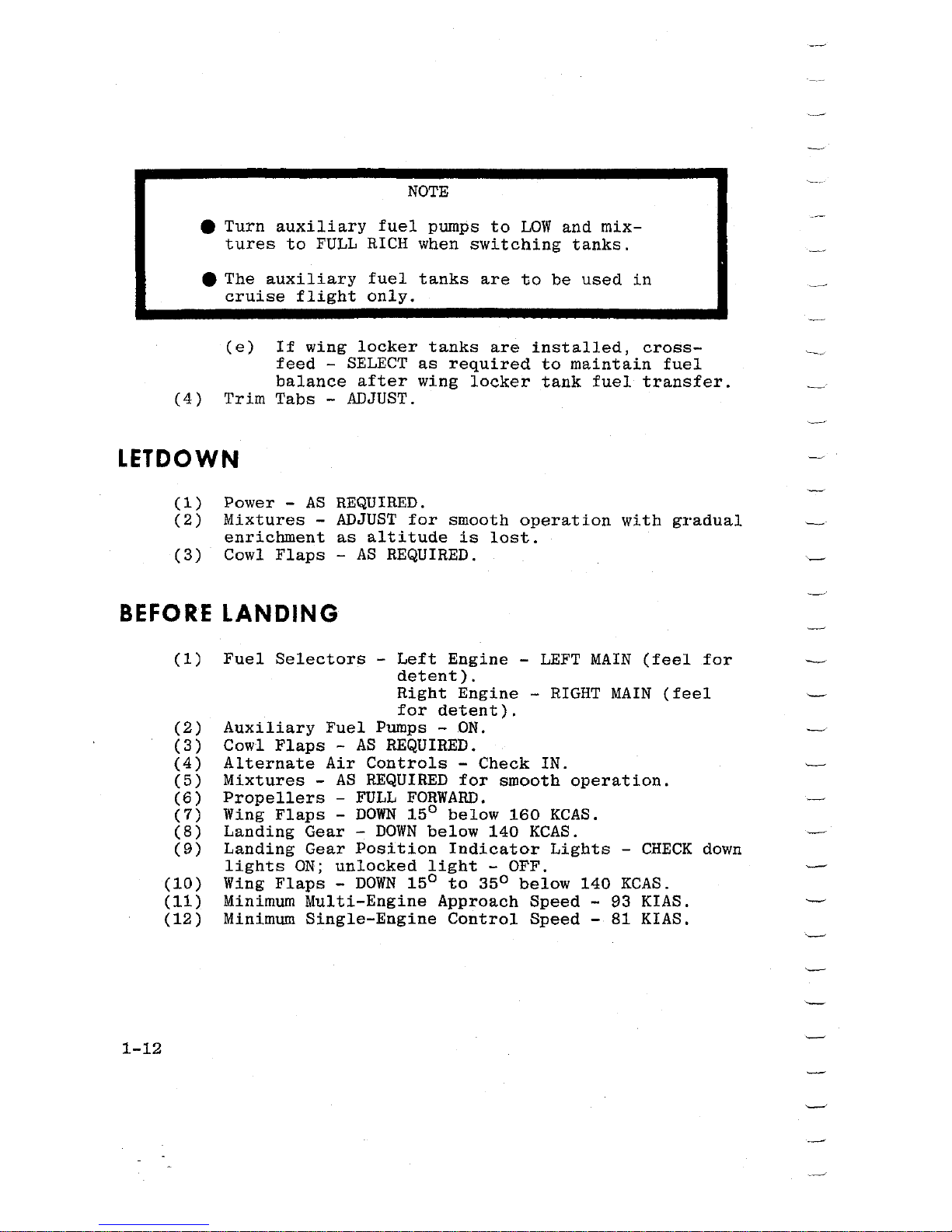
NOTE
e
Turn
auxiliary
fuel
pumps
to
LOW
and
mix-
tures
to
FULL
RICH
when
switching
tanks.
e The
auxiliary
fuel
tanks
are
to
be
used
in
cruise
flight
only.
(e)
If
wing
locker
tanks
are
installed,
cross-
feed -SELECT
as
required
to
maintain
fuel
balance
after
wing
locker
tank
fuel
transfer.
(4)
Trim
Tabs -ADJUST.
LETDOWN
(1)
Power -
AS
REQUIRED.
(2)
Mixtures
-
ADJUST
for
smooth
operation
with
gradual
enrichment
as
altitude
is
lost.
(3)
Cowl
Flaps
-
AS
REQUIRED.
BEFORE
LANDING
1-12
(1)
Fuel
Selectors
-
Left
Engine -LEFT
MAIN
(feel
for
detent).
Right
Engine -RIGHT
MAIN
(feel
for
detent).
(2)
Auxiliary
Fuel
Pumps -
ON.
(3)
Cowl
Flaps -AS
REQUIRED.
(4)
Alternate
Air
Controls
-
Check
IN.
(5)
Mixtures
-
AS
REQUIRED
for
smooth
operation.
(6)
Propellers
-
FULL
FORWARD.
(7)
Wing
Flaps -DOWN
15°
below
160
KCAS.
(8)
Landing
Gear -DOWN
below
140
KCAS.
(9)
Landing
Gear
Position
Indicator
Lights
-
CHECK
down
lights
ON;
unlocked
light
- OFF.
(10)
Wing
Flaps -DOWN
15°
to
35o
below
140
KCAS.
(11)
Minimum
Multi-Engine
Approach
Speed
- 93 KIAS.
(12)
Minimum
Single-Engine
Control
Speed
- 81 KIAS.
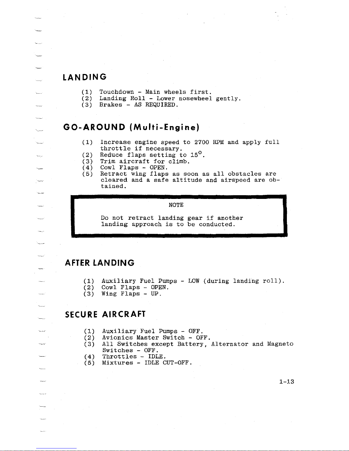
LANDING
(1)
Touchdown
-
Main
wheels
first.
(2)
Landing
Roll
-
Lower
nosewheel
gently.
(3)
Brakes
-
AS
REQUIRED.
GO-AROUND
(Multi-Engine)
(1)
Increase
engine
speed
to
2700
RPM
and
apply
full
throttle
if
necessary.
(2)
Reduce
flaps
setting
to
15°
(3)
Trim
aircraft
for
climb.
(4)
Cowl
Flaps
- OPEN.
(5)
Retract
wing
flaps
as
soon
as
all
obstacles
are
cleared
and a safe
altitude
and
airspeed
are
ob-
tained.
NOTE
Do
not
retract
landing
gear
if
another
landing
approach
is
to
be
conducted.
AFTER
LANDING
(1)
Auxiliary
Fuel
Pumps -LOW
(during
landing
roll).
(2)
Cowl
Flaps
- OPEN.
(3)
Wing
Flaps
- UP.
SECURE AIRCRAFT
(1)
Auxiliary
Fuel
Pumps
- OFF.
(2)
Avionics
Master
Switch
- OFF.
(3)
All
Switches
except
Battery,
Alternator
and
Magneto
Switches
- OFF.
(4)
Throttles
- IDLE.
(5)
Mixtures
- IDLE CUT-OFF.
1-13
1-14
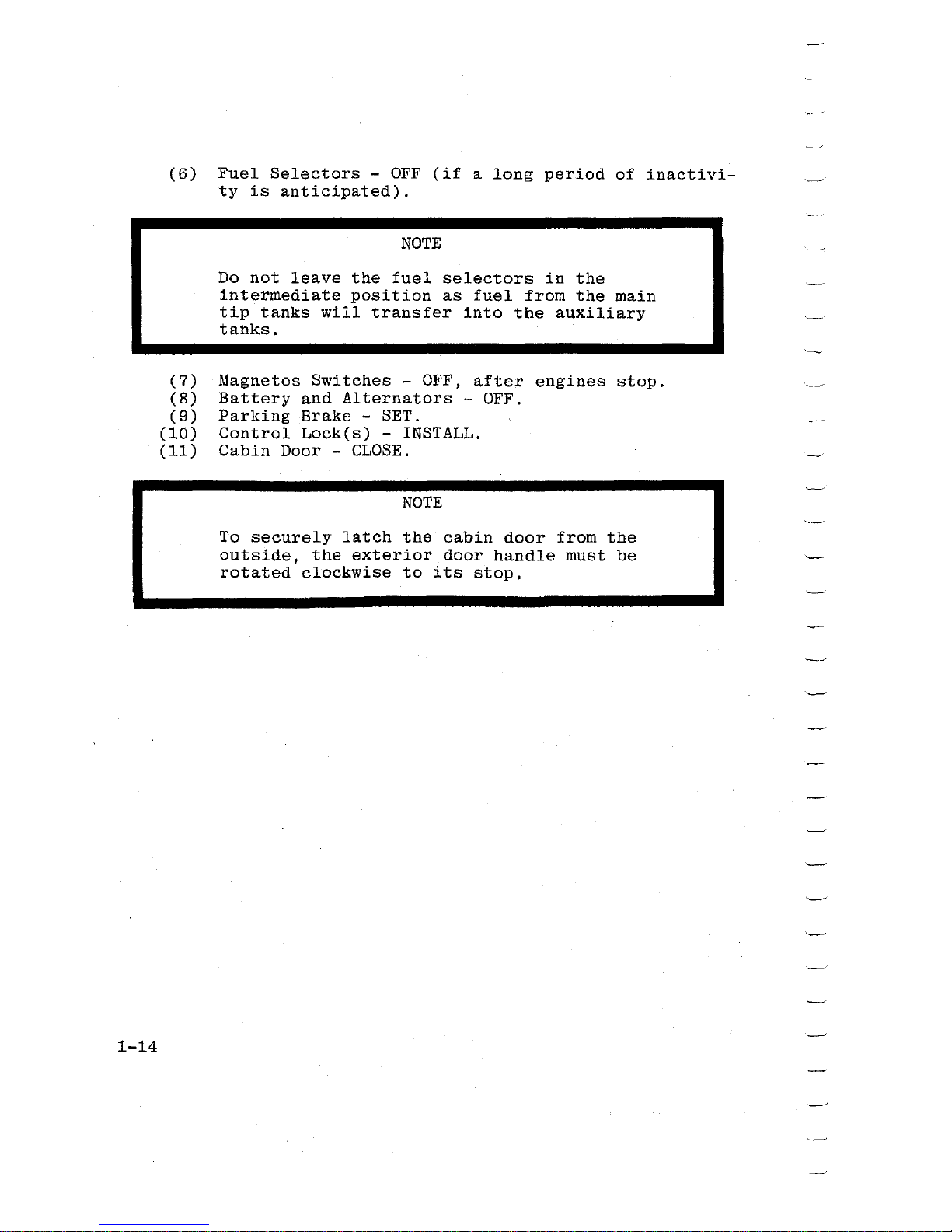
(6)
Fuel
Selectors
-
OFF
(if
a
long
period
of
inactivi-
ty
is
anticipated).
NOTE
Do
not
leave
the
fuel
selectors
in
the
intermediate
position
as
fuel
from
the
main
tip
tanks
will
transfer
into
the
auxiliary
tanks.
(7)
Magnetos
Switches
- OFF,
after
engines
stop.
(8)
Battery
and
Alternators
- OFF.
(9)
Parking
Brake
- SET.
(10)
Control
Lock(s)
-
INSTALL.
(11)
Cabin
Door -
CLOSE.
NOTE
To
securely
latch
the
cabin
door
from
the
outside,
the
exterior
door
handle
must
be
rotated
clockwise
to
its
stop.
~~©LFD®~
DD
DESCRIPTION AND
OPERATING
DETAILS
The
following
paragraphs
supply
a
general
description
of
some
systems
and
equipment
in
the
aircraft.
This
section
also
covers,
in
somewhat
greater
detail,
some
of
the
items
in
Checklist
Form
in
Section
I.
Only
those
items
of
the
Check-
list
requiring
further
explanation
will
be
covered
here.
PREFLIGHT INSPECTION
The
preflight
inspection,
described
in
Section
I,
is
recommended
for
the
first
flight
of
the
day.
Inspection
procedures
for
subsequent
flights
are
normally
limited
to
brief
checks
of
the
tail
surface
hinges,
fuel
and
oil
quanti-
ty,
and
security
of
fuel
and
oil
filler
caps.
If
the
air-
craft
has
been
in
extended
storage,
has
had
recent
major
maintenance,
or
has
been
operated
from
marginal
airports,
a
more
extensive
preflight
inspection
is
recommended.
After
major
maintenance
has
been
performed,
the
flight
and
trim
tab
controls
should
be
double-checked
for
free
and
correct
movement
and
security.
The
security
of
all
inspection
plates
on
the
aircraft
should
be
checked
following
periodic
inspection.
Since
radio
maintenance
requires
the
mechanic
to
work
in
the
forward
nose
compartment,
the
nose
cap
is
removed
for
access
to
equipment.
Therefore,
it
is
important
after
such
maintenance
to
double-check
the
security
of
the
nose
cap.
If
the
aircraft
has
been
waxed
or
polished,
check
the
external
static
pressure
source
holes
for
stoppage.
If
the
aircraft
has
been
exposed
to
much
ground
handling
in a crowded
hangar,
it
should
be
checked
for
dents
and
scratches
on
wings,
tip
tanks,
fuselage,
and
tail
surfaces,
as
well
as
damage
to
navigation
and
landing
lights,
deice
boots,
and
radio
antenna.
Outside
storage
for
long
periods
may
result
in
water
and
obstructions
in
airspeed
system
lines,
condensation
in
fuel
tanks,
and
dust
and
dirt
on
the
intake
air
filters
and
engine
cooling
fins.
Outside
storage
in
windy
or
gusty
areas,
or
adjacent
to
taxiing
aircraft
2-1
calls
for
special
attention
to
control
surface
stops,
hinges
and
brackets
to
detect
the
presence
of
wind
damage.
If
the
aircraft
has
been
operated
from
muddy
fields
or
in
snow
and
slush,
check
the
main
gear
wheel
and
nose
gear
wheel
wells
for
obstructions
and
cleanliness.
Operation
from
a
gravel
or
cinder
field
will
require
extra
attention
to
propeller
tips
and
abrasion
on
leading
edges
of
the
horizon-
tal
tail.
Stone
damage
to
the
outer
six
inches
of
the
pro-
peller
tips
can
seriously
reduce
the
fatigue
life
of
the
blades.
Aircraft
that
are
operated
from
rough
fields,
especially
at
high
altitudes,
are
subjected
to
abnormal
landing
gear
abuse.
Check
frequently
all
components
of
the
landing
gear
retracting
mechanisms,
shock
struts,
tires
and
brakes.
Undue
landing
and
taxi
loads
will
be
subjected
on
the
aircraft
structure
when
the
shock
struts
are
insufficiently
extended.
A
completely
collapsed
(zero
extension)
shock
strut
could
cause a malfunction
in
the
landing
gear
retraction
system.
To
prevent
loss
of
fuel
in
flight,
make
sure
main
and
auxiliary
fuel
tank
filler
caps
are
tightly
sealed.
The
main
fuel
tank
vents
beneath
the
tip
tanks
should
also
be
inspect-
ed
for
obstructions,
ice
or
water,
especially
after
operation
in
cold,
wet
weather.
The
interior
inspection
will
vary
according
to
the
mission
and
the
optional
equipment
installed.
Prior
to
high-
altitude
flights,
it
is
important
to
check
the
condition
and
quantity
of
oxygen
face
masks
and
hose
assemblies.
The
oxygen
supply
system
should
be
functionally
checked
to
insure
that
it
is
in
working
order.
The
oxygen
pressure
gage
should
indicate
between
300
and
1800
PSI
depending
upon
the
antici-
pated
requirements.
Satisfactory
operation
of
the
pitot
tube,
stall
warning
transmitter
and
fuel
tank
vent
heating
elements
is
determined
by
observing
a
discharge
on
the
ammeter when
the
pitot
heat
and
stall
vent
heat
switches
are
turned
ON.
The
effective-
ness
of
these
heating
elements
may
be
verified
by
cautiously
feeling
the
heat
of
these
devices
while
the
switches
are
ON.
Flights
at
night
and
in
cold
weather
involve
a
careful
check
of
other
specific
areas
which
will
be
discussed
later
in
this
section.
2-2
STARTING
ENGINES
The
left
engine
is
normally
started
first
because
the
cable
from
the
battery
to
this
engine
is
much
shorter
permit-
ting
more
electrical
power
to
be
delivered
to
the
starter.
If
battery
is
low,
the
left
engine
should
start
more
readily.
When
using
an
external
power
source,
it
is
recommended
to
start
the
aircraft
with
the
battery
and
alternator
switch-
es
OFF.
NOTE
Release
starter
switch
as
soon
as
engine
fires
or
engine
will
not
accelerate
and
flooding
can
result.
The
continuous
flow
fuel
injection
system
will
start
spraying
fuel
in
the
engine
intake
ports
as
soon
as
the
primer
switch
is
actuated
and
the
throttle
and
mixture
con-
trols
are
opened.
If
the
auxiliary
pump
is
turned
on
acci-
dentally
while
the
engine
is
stopped,
with
the
throttle
open
and
the
mixture
rich,
liquid
fuel
will
collect
temporarily
in
the
cylinder
intake
ports.
The
quantity
of
fuel
collected
will
depend
upon
the
amount
of
throttle
opening
and
the
length
of
time
the
pump
has
been
operating.
If
this
happens,
it
is
advisable
to
wait
a few
minutes
until
the
fuel
drains
away,
then
turn
the
propeller
through
15
complete
revolu-
tions.
This
is
done
to
prevent
the
possibility
of
engine
damage due
to
hydrostatic
lock
before
starting
the
engine.
To
avoid
flooding,
begin
cranking
the
engine
prior
to
priming
the
engine.
NOTE
Caution
should
be
exercised
to
prevent
overpriming
the
engine
in
hot
weather.
Engine
mis-starts
characterized
by
weak,
intermittent
explosions,
followed
by
black
puffs
of
smoke
from
the
exhaust
are
the
result
of
flooding
or
overpriming.
This
situation
is
more
apt
to
develop
in
hot
weather,
or
when
the
engines
are
2-3
hot.
If
it
occurs,
repeat
the
starting
procedure
with
the
throttle
approximately
1/2
open,
the
mixture
in
IDLE
CUT-OFF
and
the
primer
switch
OFF.
As
the
engine
fires,
move
the
mixture
control
to
FULL
RICH
and
close
the
throttle
to
idle.
If
an
engine
is
underprimed,
as
may
occur
in
cold
wea-
ther
with a cold
engine,
repeat
the
starting
procedure
while
holding
the
primer
switch
on
for
5
to
10
seconds
until
the
engine
fires.
If
cranking
longer
than
30
seconds
is
required,
allow
starter-motor
to
cool
five
minutes
before
cranking
again,
since
excessive
heat
may damage
the
armature
windings.
After
the
engines
are
started,
the
auxiliary
fuel
pumps
should
be
switched
to
LOW
to
provide
for
improved
purging
and
vapor
clearing
in
the
fuel
system.
TAXIING
A
steerable
nosewheel,
interconnected
with
the
rudder
system,
provides
positive
control
up
to
1s
0
left
or
right,
and
free
turning
from
18°
to
55°
for
sharp
turns
during
taxiing.
Normal
steering
may
be
aided
through
use
of
dif-
ferential
power
and
differential
braking
on
the
main
wheels.
These
aids
are
listed
in
the
preferred
order
of
use.
NOTE
If
the
aircraft
is
parked
with
the
nosewheel
castered
in
either
direction,
initial
taxi-
ing
should
be
done
with
caution.
To
straight-
en
the
nosewheel,
use
full
opposite
rudder
and
differential
power
instead
of
differen-
tial
braking.
After
a few
feet
of
forward
travel,
the
nosewheel
will
steer
norm~lly.
At some
time
early
in
the
taxi
run,
the
brakes
should
be
tested,
and
any
unusual
reaction,
such
as
uneven
braking,
should
be
noted.
If
brake
operation
is
not
satisfactory,
the
aircraft
should
be
returned
to
the
tie-down
location
and
the
malfunction
corrected.
The
operation
of
the
turn-and-bank
indicator
and
directional
gyro
should
also
be
checked
during
taxiing.
2-4
Most
of
the
engine
warm-up
should
be
done
during
taxi-
ing,
with
just
enough
power
to
keep
the
aircraft
moving.
Engine
speed
should
not
exceed
1000
RPM
while
the
oil
is
cold.
BEFORE
TAKEOFF
(Use
the Pilot's Checklist}
Use
the
Pilot's
Checklist
in
the
aircraft
to
prevent
the
possibility
of
overlooking
an
important
check
item.
Most
of
the
warm-up
will
have
been
conducted
during
taxi,
and
additional
warm-up
before
takeoff
should
be
re-
stricted
to
the
checks
outlined
in
Section
I.
Full
throttle
checks
on
the
ground
are
not
recommended
unless
there
is
good
reason
to
suspect
that
the
engines
are
not
operating
properly.
Do
not
runup
the
engines
over
loose
gravel
or
cinders
because
of
possible
stone
damage
or
abra-
sion
to
the
propeller
tips.
If
the
ignition
system
produces
an
engine
speed
drop
in
excess
of
150
RPM,
or
if
the
drop
in
RPM
between
the
left
and
right
magnetos
differs
by
more
than
50
RPM,
continue
warmup a
minute
or
two
longer,
before
rechecking
the
~stem.
If
there
is
doubt
concerning
operation
of
the
ignition
system,
checks
at
higher
engine
speed
will
usually
confirm
if a deficiency
exists.
In
general,
a
drop
in
excess
of
150
RPM
is
not
considered
acceptable.
If
instrument
flights
are
contemplated,
a
careful
check
should
be
made
of
the
vacuum
system.
The minimum
and
maximum
allowable
suctions
are
4.75
and
5.25
inches
Hg.,
respective-
ly,
on
the
instrument.
Good
alternator
condition
is
also
important
for
instrument
flight,
since
satisfactory
operation
of
all
radio
equipment
and
electrical
instruments
is
essen-
tial.
The
alternators
are
checked
during
engine
runup
(1700
RPM)
by
positioning
the
selector
switch
in
the L ALT
and
R
ALT
position
and
observing
the
charging
rate
on
the
volt-
ammeter.
A
simple
last
minute
recheck
of
important
items
should
include
a
quick
glance
to
see
if
all
switches
are
ON,
the
mixture
and
propeller
pitch
levers
are
forward,
all
flight
controls
have
free
and
correct
movement,
and
the
fuel
selec-
tors
are
properly
positioned.
2-5
A
mental
review
of
all
single-engine
speeds,
procedures,
and
field
length
requirements
should
be
made
prior
to
takeoff.
TAKEOFF
Since
the
use
of
full
throttle
is
not
recommended
in
the
static
runup,
closely
observe
full-power
engine
operation
early
in
the
takeoff
run.
Signs
of
rough
engine
operation,
unequal
power
between
engines,
or
sluggish
engine
accelera-
tion
are
good
cause
for
discontinuing
the
takeoff.
If
this
occurs,
you
are
justified
in
making a thorough,
full
throt-
tle,
static
runup
before
another
takeoff
is
attempted.
For
maximum
engine
power,
the
mixture
should
be
adjusted
during
the
initial
acceleration
to
the
recommended
fuel
flow
for
the
field
elevation.
The
engine
acceleration
is
increas-
ed
significantly
with
fuel
leaning
above
3000
feet
and
this
procedure
always
should
be
employed
for
field
elevations
greater
than
5000
feet
above
sea
level.
Refer
to
the
Pilot's
Checklist
for
recommended
fuel
flows.
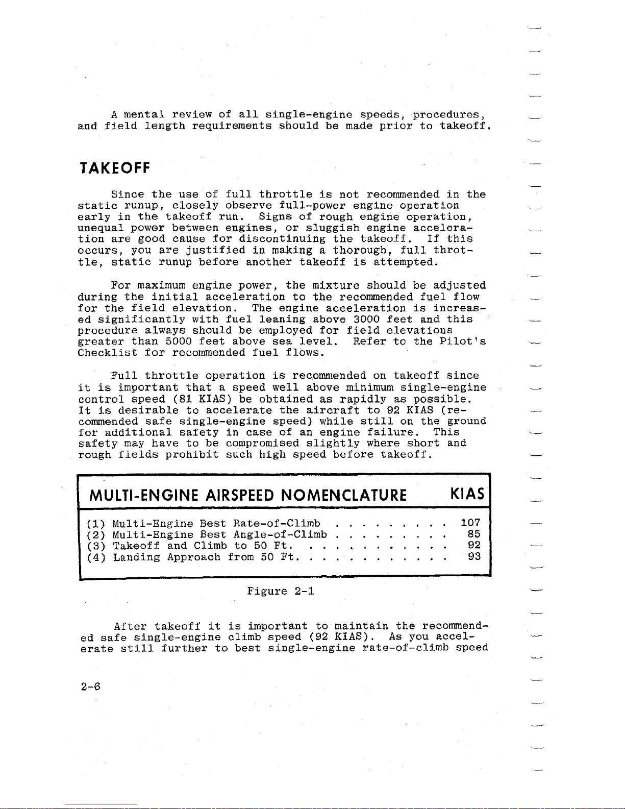
Full
throttle
operation
is
recommended
on
takeoff
since
it
is
important
that
a
speed
well
above
minimum
single-engine
control
speed
(81
KIAS)
be
obtained
as
rapidly
as
possible.
It
is
desirable
to
accelerate
the
aircraft
to
92
KIAS
(re-
commended
safe
single-engine
speed)
while
still
on
the
ground
for
additional
safety
in
case
of
an
engine
failure.
This
safety
may
have
to
be
compromised
slightly
where
short
and
rough
fields
prohibit
such
high
speed
before
takeoff.
MULTI-ENGINE
AIRSPEED
NOMENCLATURE
(1)
Multi-Engine
Best
Rate-of-Climb
(2)
Multi-Engine
Best
Angle-of-Climb
(3)
Takeoff
and
Climb
to
50
Ft.
(4)
Landing
Approach
from
50
Ft
..
Figure
2-1
KIAS
107
85
92
93
After
takeoff
it
is
important
to
maintain
the
recommend-
ed
safe
single-engine
climb
speed
(92
KIAS).
As
you
accel-
erate
still
further
to
best
single-engine
rate-of-climb
speed
2-6
(107 KIAS),
it
is
good
practice
to
climb
rapidly
to
an
alti-
tude
at
which
the
aircraft
is
capable
of
circling
the
field
on
one
engine.
After
obstruction
height
is
reached,
power
may
be
re-
duced
and
climb
speeds
may
be
established
as
described
in
Section
I.
For
crosswind
takeoffs,
additional
power
may
be
carried
on
the
upwind
engine
until
the
rudder
becomes
effective.
The
aircraft
is
accelerated
to a slightly
higher
than
normal
takeoff
speed,
and
then
is
pulled
off
abruptly
to
prevent
possible
settling
back
to
the
runway
while
drifting.
When
clear
of
the
ground,
a
coordinated
turn
is
made
into
the
wind
to
correct
for
drift.
A
takeoff
with
one
tip
tank
full
and
the
opposite
tank
empty
creates
a
lateral
unbalance
at
takeoff
speed.
This
is
not
recommended
since
gusty
air
or
premature
lift-off
could
create
a
serious
control
problem.
Performance
data
for
normal
takeoff,
accelerate
stop
distance
and
single-engine
takeoff
are
presented
in
Section
VI.
AFTER
TAKEOFF
To
establish
climb
configuration,
retract
the
landing
gear,
adjust
power
for
climb,
turn
off
the
auxiliary
fuel
pumps
and
adjust
the
mixture
for
the
power
setting
selected.
Before
retracting
the
landing
gear,
apply
the
brakes
momentarily
to
stop
the
main
wheels.
Centrifugal
force
caused
by
the
rapidly-rotating
wheels
expands
the
diameter
of
the
tires,
and
if
ice
or
mud
has
accumulated
in
the
wheel
wells,
the
rotating
wheels
may
rub
as
they
enter.
On
long
runways,
the
landing
gear
should
be
retracted
at
the
point
over
the
runway
where a wheels-down
forced
landing
on
that
runway
would
become
impractical.
However,
on
short
runways
it
may
be
preferable
to
retract
the
landing
gear
after
the
aircraft
is
safely
airborne.
Power
reduction
will
vary
according
to
the
requirements
of
the
traffic
pattern
or
surrounding
terrain,
gross
weight,
field
elevation,
temperature
and
engine
condition.
However,
2-7
a
normal
"after
takeoff"
power
setting
is
24.5
inches
Hg.
and
2500
RPM.
CLIMB
To
save
time
and
fuel
for
the
over-all
trip,
it
is
recommended
that
the
normal
cruising
climb
be
conducted
at
115-130
KIAS
using
approximately
75%
power
(24.5
inches
Hg.
manifold
pressure
and
2500 RPM).
Cruising
climbs
should
be
conducted
at
the
recommended
fuel
flow;
refer
to
the
Pilot's
Checklist.
If
it
is
necessary
to
climb
rapidly
to
clear
mountains
or
reach
favorable
winds
at
high
altitudes,
the
best
rate-of-
climb
speed
should
be
used
with
maximum
power.
This
speed
varies
from
107
KIAS
at
sea
level
to
99
KIAS
at
10,000
feet.
During
maximum
performance
climbs,
the
mixture
should
be
leaned
to
the
recommended
fuel
flow.
It
is
recommended
that
the
auxiliary
fuel
pumps
be
on
at
altitudes
above
12,000
feet
for
the
duration
of
the
climb
and
approximately
5
to
15
minutes
after
establishing
cruising
flight.
It
is
also
recommended
that
the
mixture
remain
at
the
climb
mixture
setting
for
approximately
5
minutes
after
establishing
cruis-
ing
flight
before
leaning
is
initiated.
These
procedures
will
eliminate
fuel
vaporization
problems
likely
to
occur
from
rapid
altitude
changes.
If
an
obstruction
ahead
requires
a
steep
climb
angle,
the
aircraft
should
be
flown
at
the
best
angle-of-climb
speed
with
flaps
up
and
maximum
power.
The
speed
varies
from
85
KIAS
at
sea
level
to
89
KIAS
at
15,000
feet.
Performance
data
for
maximum
climb,
cruise
climb
and
single-engine
climb
are
presented
in
Section
VI.
CRUISE
Tabulated
cruising
information
is
provided
for
normal
power
and
altitudes
in
Section
VI.
These
charts
are
based
on
600,
978
and
1218
pounds
of
fuel
for
cruise,
recommended
lean
mixture,
5500
pounds
gross
weight,
zero
wind,
and
no
fuel
reserve.
Allowances
for
warm-up,
headwinds,
variations
in
mixture
leaning
technique,
and
fuel
reserve
should
be
es-
2-8
timated,
and
the
endurance
and
range
shown
in
the
charts
should
be
modified
accordingly.
Fuel
allowances
for
takeoff
and
climb
are
given
in
Section
VI.
Normal
cruising
requires
between
50%
and
70%
power.
The
manifold
pressure
and
RPM
settings
required
to
obtain
these
powers
at
various
altitudes
and
outside
air
temperatures
can
be
determined
with
your
power
computer.
A maximum
cruising
power
of
approximately
75%
(24.5
inches
Hg.,
and
2500
RPM)
may
be
used
if
desired.
Various
percent
powers
can
be
ob-
tained
with a number
of
combinations
of
manifold
pressures,
engine
speeds,
•altitudes,
and
outside
air
temperatures.
However,
at
full
throttle
and
constant
engine
speed,
a
speci-
fic
power
can
be
obtained
at
only
one
altitude
for
each
given
air
temperature.
For a given
throttle
setting,
select
the
lowest
engine
speed
in
the
green
arc
range
that
will
give
smooth
engine
operation
without
evidence
of"'laboring.
The
use
of
lower
power
settings
and
the
selection
of
cruise
altitude
on
the
basis
of
the
most
favorable
wind
conditions
are
significant
factors
that
should
be
considered
on
every
trip
to
reduce
fuel
consumption.
Additional
range
can
be
achieved
when
operating
at
55%
power
or
less
by
lean-
ing
to
peak
exhaust
gas
temperature
(EGT)
for
Best
Economy
mixture.
Refer
to
Economy
Mixture
Indicator
in
Section
VII
if
the
optional
EGT
system
is
installed.
If
the
EGT
system
is
not
installed,
lean
to a fuel
flow
of 6 pounds
per
hour
per
engine
less
than
the
Recommended Lean
fuel
flow
shown on
the
power
computer
or
the
cruise
performance
charts
shown
in
Section
VI.
This
setting
results
in
an
airspeed
loss
of
4
KTAS
and
range
increase
of
8%
compared
to
the
Recommended
Lean
mixture.
Do
not
lean
to
the
extent
that
engine
rough-
ness
or
excessive
speed
loss
occurs.
CAUTION
Best
economy
mixture
operation
at
55%
power
or
less
is
not
recommended
until
oil
consump-
tion
stabilizes
or
during
the
first
50
hours
of
operation.
The
purpose
of
this
interval
of
operation
at
higher
power
levels
(65%
to
75%
power)
is
to
insure
proper
seating
of
the
rings
and
is
applicable
to
new
engines,
and
engines
in
service
following
cylinder
replacement
or
top
overhaul
of
one
or
more
cylinders.
2-9
When
leaning,
accomplish
the
procedure
as
precisely
as
possible.
A
little
extra
effort
in
setting
the
mixtures
will
yield
significant
dividends.
For
normal
cruise
conditions,
your
power
computer
should
be
utilized
to
set
the
fuel
flows.
The
power
computer
is
based
on
true
OAT,
which
is
obtained
by
subtracting
the
ram
rise
from
the
indicated
OAT.
A
ram
rise
chart
is
provided
in
the
pilot's
checklist.
The
power
computer
is
marked
with
two
fuel
flow
scales.
These
scales
are
provided
to
ensure
that
you
can
obtain
the
maximum
performance
and
utilization
from
your
Cessna.
The
inner
fuel
flow
scale
(marked
Recommended
Lean)
should
be
utilized
for
all
normal
cruise
performance.
Data
shown
in
Section
VI
are
based
on Recommended Lean
mix-
ture.
The
outer
fuel
flow
scale
(marked
Best
Power)
will
provide
maximum
speed
for a given
power
setting.
The
speed
will
be
approximately
one
knot
greater
than
the
speed
with
Recommended
Lean
mixture.
Operation
at
Best
Power
mixture
will
increase
the
life
of
the
exhaust
system
and
engine
valves
and
rings.
For
best
propeller
synchronizing,
the
final
adjustment
of
the
propeller
controls
should
be
made
in a DECREASE
RPM
direction.
The
internal
cowl
flaps
should
normally
be
locked
and
left
in
the
FULL
OPEN
position
for
all
flight
and
ground
operations,
particularly
on
hot
days.
Unlike
external
cowl
flaps
that
are
designed
to
reduce
engine
temperatures,
the
internal
cowl
flaps
are
designed
to
increase
engine
tempera-
tures
during
low power
climb,
cruise,
descent,
and
operations
in
below
standard
ambient
conditions.
The
cowl
flaps
should
be
adjusted
to
modulate
the
cylinder
head
temperatures
near
the
center
of
the
normal
operating
(green
arc)
range
to
assure
prolonged
engine
life.
Cowl
flap
position
has
no
effect
on
cruise
or
climb
performance.
For
flight
in
an
icing
environment,
refer
to
the
alter-
nate
induction
air
system
in
the
following
paragraph.
2-10
 Loading...