


PERFORMANCESP E CIFI
CATIONS
CESSNA
MODEL
150M
PERFORMANCE -SPECIFICATIONS
SPEED:
Maximum
at
Sea
Level
. . , . . . . . . . . . . . . 109 KNOTS
Cruise,
75%
Power
at
7000
Ft
............
106 KNOTS
CRUISE:
Recommended
Lean
Mixture
with
fuel
allowance
for
engine
start,
taxi,
takeoff,
climb
and
45
minutes
reserve
at
45%
power.
75%
Power
at
7000
Ft
...
22.5
Gallons
Usable
Fuel
75%
Power
at
7000
Ft
...
35
Gallons
Usable
Fuel
Maximum
Range
at
10,000
Ft
22.5
Gallons
Usable
Fuel
Maximum
Range
at
10,000
Ft
35
Gallons
Usable
Fuel
RA
TE
OF
CLIMB
AT
SEA
LEVEL
SERVICE
CEILING
...
_
TAKEOFF
PERFORMANCE:
Ground
Roll . . . . . .
Total
Distance
Over
50-
Ft
Obstacle
LANDING
PERFORMANCE:
Ground
Roll
. . . . . . . . . . .
Total
Distance
Over
50-
Ft
Obstacle
STALL
SPEED
(CAS):
Flaps
Up,
Power
Off . .
Flaps
Down,
Power
Off .
MAXIMUM WEIGHT . . . .
STANDARD
EMPTY
WEIGHT:
Commuter
.....
.
Commuter
II.
. . . .
MAXIMUM
USEFUL
LOAD:
Commuter
.....
.
Commuter
II.
. . . .
BAGGAGE ALLOWANCE . . .
WING LOADING:
Pounds/Sq
Ft
POWER
LOADING:
Pounds/HP
FUEL
CAPACITY:
Total
Standard
Tanks
.....
Long
Range
Tanks
. . . .
OIL
CAPACITY
. . . . . . .
ENGINE:
Teledyne
Continental
100
BHP
at
2750
RPM
PROPELLER:
Fixed
Pitch,
Diameter
I S-13- RAN D--18
000
-{)/20/75
Range
Time
Range
Time
Range
Time
Range
Time
340 NM
3.3
HRS
580 NM
5.5
HRS
420
NM
4.9
HRS
735NM
8.5
HRS
670
FPM
14,000
FT
735
FT
1385
FT
445
FT
1075
FT
48 KNOTS
42 KNOTS
1600 LBS
1104 LBS
1122 LBS
496
LBS
478 LBS
120 LBS
10.0
16.0
26 GAL.
38 GAL.
6
QrS
0-200-A
69 IN.
i
R\C.lACL~cf
K
Le
l~
rJ
I
PILOT'S
OPERATING HANDBOOK
~
Cessna.
150
COMMUTER
1976
MODEL
150M
Serial
No
__________
_
Registration
No.
______
_
THIS
HANDBOOK
INCLUDES
THE
MATERIAL
REQUIRED
TO
BE
FURNISHED
TO
THE
PILOT
BY
CAR
PART
3
CESSNA AIRCRAFT
COMPANY
WICHIT A,
KANSAS,
USA

CONGRA
TULA
TIO
NS
CESSNA
MODEL
150M
CONGRATULATIONS
....
Welcome
to
the
ranks
of
Cessna owners!
Your
Cessna has been designed and
constructed
to
give
you
the
most
in
performance,
economy,
and
comfort.
It
is
our
desire
that
you
will find
flying it,
either
for business
or
pleasure, a pleasant and profitable experience.
This
handbook
has been prepared as a guide
to
help you get
the
most
pleasure
and
utility
from
your
airplane. It
contains
information
about
your
Cessna's
equipment,
operating
pro·
cedures, and performance;
and
suggestions for its servicing
and
care.
We
urge you
to
read
it from cover
to
cover,
and
to
refer
to
it frequently.
Our
interest
in
your
flying pleasure has
not
ceased with
your
purchase
of
a Cessna. World-
wide,
the
Cessna Dealer Organization backed by
the
Cessna Service
Department
stands
ready
to
serve
you.
The
following services are offered by
most
Cessna Dealers:
TH E CESSNA
WAR
RANTY - - It
is
designed
to
provide
you
with
the
most
compre-
hensive coverage possible:
a.
No exclusions
b. Coverage includes parts and labor
c.
Available
at
Cessna Dealers world wide
d. Best
in
the
industry
Specific benefits
and
provisions
of
the
warranty
plus
other
important
benefits for
you
are
contained
in
your
Customer
Care Program
book
supplied with
your
airplane.
Warranty service
is
available
to
you
at
any
authorized
Cessna Dealer
throughout
the
world
upon
presentation
of
your
Customer
Care Card wh ich establishes
your
eligibil-
ity
under
the
warranty.
FACTORY TRAINED PERSONNEL
to
provide you with
courteous
expert
service.
FACTORY APPROVED SERVICE EQUIPMENT
to
provide you with
the
most
efficient
and
accurate
workmanship
possible.
A STOCK OF GENUINE CESSNA SERVICE PARTS
on
hand when you need
them.
THE
LATEST AUTHORITATIVE INFORMATION FOR SERVICING CESSNA
AI
RPLANES, since Cessna Dealers have all
of
the
Service Manuals and Parts
Catalogs,
kept
current
by Service Letters and Service News Letters, published by
Cessna Aircraft Company.
We
urge all Cessna owners
to
use
the
Cessna Dealer Organization
to
the
fullest.
A
current
Cessna Dealer Directory accompanies
your
new airplane. The Directory
is
revised
frequently,
and a current
copy
can be
obtained
from
your
Cessna Dealer. Make
your
Directory
one
of
your
cross-country flight planning aids; a warm welcome awaits
you
at
every Cessna Dealer.
ii
CESSNA
MODEL
150M
TA
BLE
OF
CONTENT
S
TAB
LE
OF
CONTENTS
GENERAL
LI
MITATIONS
EMERGENCY PROCEDURES
NORMAL
PROCEDUR
ES
PERFORMANC
E . . . .
WEIGHT
& BALA
NC
E/
SE
CTION
1
2
3
4
5
EQ
UIPME
NT LIST. . . .
.....
•.
..
6
AIRPLANE & SYSTEMS
DESCRIPTIONS.
. . . . . . . . . . . . . . 7
AIRPLANE
HAN
DLI
NG,
SERVICE
& MAINTENANCE. . . . . . . . . 8
SUP
PLEMENTS
(Op
tion
al
Systems
Description
&
Op
erating Procedures) . . . . . . . • . . 9
This hand
book
will be
kept
curre
nt
by Service Letters published by Cessna Aircraft
Company. These are d istrib
uted to
Cessna Dealers and
to
those
who. su.bscnbe.
through
the
Owner Fo llow-Up System . If
you
are
not
receiving subSCription
serVic
e,
you will
want
to
keep in
touc
h with
your
Cessna Dealer
for
Information concerning
the
change
status
of
the
handbook. Subseq
uent
changes will be made
in
the
form
of
stickers. These should be
examined
and
attached
to
the
appropnate
page
In
the
handbook
immediately
after
receipt; the handbook should
not
be used
for
opera-
tional purposes until it has been
updated
to a current
status.

CESSNA
MODEL
150M
SECTION
1
GENERAL
TABLE
OF
CONTENTS
Three
View
..
Introduction
. .
Descriptive
Data
Engine
.
Propeller
Fuel
..
Oil
...
Maximum
Certificated
Weights
Standard
Airplane
Weights
Cabin
and
Entry
Dimensions
Baggage
Space
Dimensions
Specific
Loadings
..
. . .
Symbols,
Abbreviations
and
Terminology
General
Airspeed
Terminology
and
Symbols.
Meteorological
Terminology.
. . . . . . .
Engine
Power
Terminology
. . . . . . . .
Airplane
Performance
and
Flight
Planning
Terminology
Weight
and
Balance
Terminology.
. . . . . . . . . .
SECTION
1
GENERAL
Page
1-2
1-3
1-3
1-3
1-3
1-3
1-4
1-5
1-5
1-5
1-5
1-5
1-5
1-5
1-6
1-7
1-7
1-7
1-1

SECT ION 1
GE
NERA
L
; ..
NOT E
S:
CESSNA
MOD
EL
150M
1.
Wi
ng span shown
with strobe
lights installed .
2.
Maxim
um heig
ht shown w
ith nose gea
r de-
pressed, a
ll
tires
and
nose strut properly in-
fl
at
ed, a nd flash ing beac
on installed.
3. Wheel b
ase
length is 58" ,
4.
Pro
peJler ground clearance
is
12" .
5.
Wing
area
is
160 squa
re
feet .
6. Mi
nimum
turni
ng
radius 1* p
ivot poi
nt
to
outboard
win
g tip ) is 24'
8",
II-
' -
33
'-4"-
-1'1
I)
Figure 1-1. Thr
ee Vie
w
1-2
CE
SSNA
MOD
EL 150M
SECTIO
N 1
GENERAL
I
NTRODUCTION
This
handbook
contains 9 sections,
and
includes
the
material
require
d
to
be
furnished
to
the
pilot
by
CAR
Part
3.
It
also
contains
supplem
enta
l
da
ta
supplied
by
Cessna
Aircraft
Company.
Section 1 provides
basic
data
and
information
of
general
interest.
It
also
contains
definitions
or
explanations
of
symbols,
abbreviations,
and
terminology
commonly
used.
DESC
RIPTIVE
DATA
ENGINE
Number
of Eng
ines:
1.
Engine
Manufacturer:
Teledyne
Continental.
Engine
Model
Number:
0-200-A.
Engine
Type:
Normally-aspirated,
direct-drive,
air-cooled,
horizontally-
opposed,
carburetor
equipped,
four-cylinder
engine
with
201
cu.
in.
displacement.
Horsepower
Rating
and
Engine
Speed:
100
rated
BHP
at
2750
RPM.
PR
OPELLER
Propeller
Manufacturer:
McCauley Accessory
Division.
Propeller
Model
Number:
1A102/
0CM6948.
Num
ber
of
Blades:
2.
Pro
pell
er
Diameter,
Maximum:
69
inches.
Minimum:
67.5
inches.
Propeller Type:
Fixed
pitch.
FUEL
Fuel Grade
(and
Color):
80/87
Minimum
Grade Aviation
Fuel
(red)
.
Alternate
fuels
which
are
also
approved
are:
100/
130 Low
Lead
AVGAS (g
reen
).
(Maximum
lead
content
of
2
cc
per g
allon.
)
100/130
Aviation
Grade
Fuel (green).
(Maximum
lead
content
of 4. 6
cc
per
gallon.
)
NOTE
When
substituting a higher octane
fuel,
low
lead
AVGAS
100
shou
ld
be
used whenever
possible
since
it
will
result
.
in
les
s l
ead
contamination
of the engine.
1-
3 J
I
SECTION
1
GENERAL
CESSNA
MODEL
150M
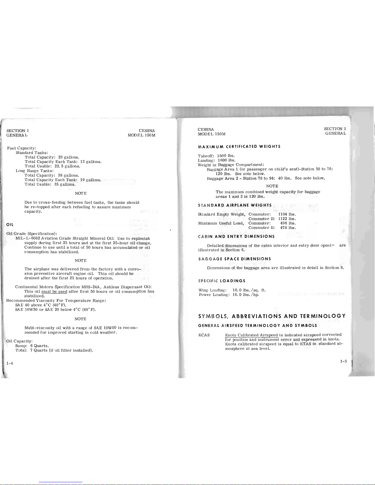
Fuel
Capacity:
OIL
Standard
Tanks
:
Total
Capacity: 26
gallons.
Total
Capacity
Each
Tank
: 13 g
all
ons.
T
otal
Usable: 22.5
gallons.
Lon
g R
ange
Tanks:
Total
Capacity:
38 g
allons
.
Total
Capacity
Each
Tank:
19 gall
ons.
Total
Usable:
35
gallons.
NOTE
Due
to
cross-feeding
between
fuel
tanks,
the tanks
should
be
re-topped
after
each
refueling
to
assure
maximum
capacity.
Oil
Grade
(Specification):
MIL-L-6082
Aviation
Grade
Straight
Mineral
Oil:
Use
to
replenish
supply
during
first
25
hours
and
at
the
first
25-hour
oil
change.
Continue
to
use
until a total
of 50
hours
has
accumulated
or
oil
consumption
has
stabilized.
NOTE
The
airplane
was
delivered
from
the
factory
with a
corro-
sion
preventive
aircraft eng
ine
oil.
This
oil
shouLd
be
drained
after
the
first
25
hours
of
operation.
Continental
Motors
Specification
MHS-24A,
Ashless
Dispersant
Oil:
This
oil
must
be
used
after
first
50
hours
or
oil
consumption
has
stabilized.
Recommended
Viscosity
For
Temperature
Range:
SAE 40
above
4°C
(40°F).
SAE
10W30
or
SAE
20
below
4°C
(40°F).
NOTE
Multi-viscosity
oil
with a range
of SAE 10W30
is
recom-
mended
for
improved
starting
in
cold
weather.
Oil
Capacity:
Sump: 6 Quarts.
Total: 7 Quarts
(if
oil
filter
installed).
1-4
CESSNA
MODEL 150M
SECTION 1
GENERAL
MAXIMUM
CERTIFICATED
WEIGHTS
T
ake
off: 1600
lbs.
Landing:
1600
lbs.
W
eight
in
Baggage
Compartment:
Baggage
Area 1 (or
passenger
on
child's
seat)-Station
50
to 76:
120
lbs.
See
note
below.
Baggage
Area
2 -
Station
76
to
94: 40
lbs.
See
note
below.
NOTE
The
maximum
combined
weight
capaCity
for
baggage
areas 1 and 2 is
120
lbs.
STAN
DARD
AIRPLANE
WEIGHTS
Standa
rd
Empty
Weight,
Commuter
:
Commuter
II:
Maxi
mum
Useful
Load,
Commuter:
Commuter
II:
CABIN
AND
ENTRY
DIMENSIONS
1104
lbs.
1122
lbs.
496
lbs.
478
lbs.
D
etailed
dimensions
of
the
cabin
interior
and
entry
door
openi:'(
are
i
llus trated in
Section
6.
BAGGAGE SPACE
DIMEN
SI O
NS
Dimensions
of
the
baggage
area
are
illustrated
in
detail
in
Section
6.
SPEC IF
IC LOA
DINGS
Wing Loading:
10.0
lbs. /sq.
ft.
Po
wer Loadi
ng:
16.0
lbs.
/hp.
S
YMBOLS
, A B
BREVIATIONS
AND
TERMINOLOGY
GE
NERAL
AIR
SP EED
TERMINOLOGY
AND
SYMBOLS
KCAS
Kno ts
Ca
librated
Airspeed
is
indicated
airspeed
corrected
for
position
and
instrument
error
and
expressed
in
knots.
Knots
calibrat
ed
airspeed
is
equal
to KTAS in
standard
at-
mosphere
at
sea
level.
1-5

SECTION
1
GENERAL
KIAS
KTAS
V
NO
CESSNA
MODEL 150M
Knots
Indicated
Airspeed
is the
speed
show
n on
the
airspeed
indicator
and
expressed
in
knot
s.
K
nots
True
Airspeed
is the a
irs
peed
expressed
in
knots rel
-
ahve
to
undIsturbed
air
which
is
KCAS
corrected
for
altitude
and
temp
era
ture.
Maneuvering
Speed
is the
maxim
um
speed
at
whi
ch
you m
ay
use
abrup
t cont
rol
trav
el.
Maximum Flap
Extended Speed
is
the
highest speed
permis-
sible
wit
h f
laps in a pre
scribed
extended position.
M
aximum
Structural
Cru
isin
g S
peed
is
the speed
that shou
ld
not
be
exceeded except in
smo
oth
air, then
only w
ith
caution.
N
ever
Exceed Speed
. is
the spe
ed
lim
it
that may no t be e
x-
c
eeded
at any
time.
Stalling Speed
or
the minimum
steady
flight spe
ed
at
which
the airplane
is
contro
llable.
Stalli
ng S
peed
or the
mini
mum
steady
flight
spe
ed
at w
hic
h
the airplane
is controllable
in
the
landing
config
uration
at
the most
forward cent
er
of
gravity.
Best
Ang
le-of-Climb
Speed
is
the
speed
which res
ults
in
the
g
reatest gain
of
altitude
in a given
horizontal
dist
anc
e.
Best
Rate-of-C
limb
Speed
is
the
speed
which
resul
ts
in the
g
reate
st gain
in
alt
itude
in a given
time
.
METEOROLOGICAL
TERMINOLOGY
OA
T
Sta
ndard
Tempe
ra-
tur
e
Pressure
Altitude
1
-6
Outsid
e A
ir Tem
perature
is
the
free
air
static tempe
r a
ture.
It
is expressed
in
either de
gre
es
Celsius
(fo
rmerly
Centi-
grade
) or degrees Fahrenhei
t.
Standard Tempera
ture
is
15° C
at
sea
level
pre
SS1ue
altitud
e
and
decreases
by
2 "c
for
eac
h 1000
feet
of alti de.
Pressure
Altitude
is
the
altitude
read
from an
altime
ter
when
the
barometric
subscale
has
been set
to 29. 92
inches
of
mercury
(1013 mb).
CESSNA
MODEL
150M
SECTION 1
G
ENERAL
ENGINE
POWER
TERMINOLO
G Y
BHP
R
PM
S
tatic
R
PM
Brake
Horsepower
is
the
power
developed
by
the
engine.
Revolutions
Per
Minute
is
engine
speed.
static
RPM
is
engine
speed
attained
during a full-throttle
en-
gine
runup when
the
airplane
is
on
the
ground
and
stationary.
AIRPLANE PERFORM
ANCE
AND
FLIGHT
PLANNING
TERMINOLOGY
De
mon
-
s
tr
ate
d
Cr
oss
wind
Ve
loc
ity
Demonstrated
Crosswind
Velocity
is
the
velocity
of
the
cross-
wind
component
for
which
adequate
control
of
the
airplane
during
takeoff
and
landing
was
actually
demonstrated
during
certification
tests.
The
value
shown
is
not
considered
to
be
limiting.
Usable
Fuel
Usable
Fuel
is
the
fuel
available
for
flight
planning.
Unusable
Fuel
GP
H
NMPG
g
Unusable
Fuel
is
the
quantity
of
fuel
that
can
not
be
safely
used
in
flight.
Gallons
Per
Hour
is
the
amount
of
fuel
(in
gallons)
consumed
per
hour.
Nautical
Miles
Per
Gallon
is
the
distance
(in
nautical
miles)
which
can
be
expected
per
gallon
of
fuel
consumed
at a spe-
cific
engine
power
setting
and/or
flight
configuration.
K
is
acceleration
due
to
gravity.
WEIGHT AND
BALANCE
TERMINOLOGY
Refe
rence
Datum
S
tatio
n
Arm
Moment
Re
ference
Datum
is
an
imaginary
vertical
plane
from
which
a
ll
horizontal
distances
are
measured
for
balance
purposes.
§.~ation
is a location
along
the
airplane
fuselage
given
in
t
erm
s of
the
distance
from
the
reference
datum.
A
rm
is
the
horizontal
distance
from
the
reference
datum
to
the
ce
nter
of
gravity
(C. G. ) of
an
item.
Moment
is
the
product
of
the
weight
of
an
item
multiplied
by
its arm. (Moment
divided
by
the
constant
1000
is
used
in
thi s h
and
book to
simplify
balance
calculations
by
reducing
the numb
er
of
digits.
)
1-7

SECTION
1
GENERAL
Center
of
Gravity
(C.
G.)
C.G.
Arm
C.G.
Limits
Standard
Empty
Weight
CESSNA
MODEL
150M
Center
of
Gravity
is
the
point
at
which
an
airplane,
or
equip-
ment,
would
balance
if
suspended.
Its
distance
from
the
reference
datum
is
found
by
dividing
the
total
moment
by
the
total
weight
of
the
airplane.
Center
of
Gravity
Arm
is
the
arm
obtained
by
adding
the
airplane's
individual
moments
and
dividing
the
sum
by
the
total
weight.
Center
of
Gravity
Limits
are
the
extreme
center
of
gravity
locations
within
which
the
airplane
must
be
operated
at
a
given
weight.
Standard
Empty
Weight
is
the
weight
of a standard
airplane,
including
unusable
fuel,
full
operating
fluids
and
full
engine
oil.
Basic
Empty
Basic
Empty
Weight
is
the
standard
empty
weight
plus
the
Weight
weight
of
optional
equipment.
Usefu
l
Load
Gros
s
(Loaded
)
Weight
Maximum
Takeoff
Weight
Maximum
Landing
Weight
Tare
1-8
Useful
Load
is
the
difference
between
takeoff
weight
and
the
basic
empty
weight.
Gross
(Loaded)
Weight
is the
loaded weig
ht
of
the
airplane.
Maximum
Takeoff
Weight
is
the maxim
um
weight
approved
for
the
start
of
the
takeoff run.
Maximum
Landing
Weight
is
the
maximum
weight
approved
for
the
landing
touchdown.
Tare
is
the
weight
of
chocks,
blocks,
stands,
etc.
used
when
weighing
an
airplane,
and
is
included
in
the
scale
readings.
Tare
is
deducted
from
the
scale
reading
to
obtain
the
actual
(net)
airplane
weight.
CESSNA
MODEL
150M
SECTION
2
LIMITATIONS
TABLE
OF
CONTENTS
Introduction
. . . . . . . .
Airspeed
Limitations
. . . .
A
irspeed
Indicator
Markings
Power
Plant
Limitations
Power
Plant
Instrument
Markings
Weight
Limits
. . . . .
Center
of
Gravity
Limits
.
Maneuver
Limits
....
Flight
Load
Factor
Limits.
Kinds
of
Operation
Limits
.
Fuel
Limitations
Placards .......
.
SECTION
2
LIMITATIO
NS
Page
2-3
2-3
2-4
2-4
2-5
2-5
2-5
2-6
2-6
2-6
2-7
2-8
2-1/(2-2
blank)

CESSNA
MODEL
150M
INTRODUCTION
SECTION
2
LIMITATIONS
Section 2 includes
operating
limitations,
instrument
markings,
and
basic
placards
necessary
for
the
safe
operation
of
the
airplane,
its
engine,
standard
systems
and
standard
equipment.
The
limitations
included
in
this
section
have
been
approved
by
the
Federal
Aviation
Administration.
When
applicable,
limitations
associated
with
optional
systems
or
equip-
ment
are
included
in
Section
9.
Your
Cessna
is
certificated
under
FAA
Type
Certificate
No. 3
A1
9
as
Cessna
Model
No. 150M.
AIR
SPEED
LIMIT
ATI
ONS
A
irspeed
limitations
and the
ir oper a
tional
signifi
can
ce
are
sho
wn
in
figure
2-1.
SPEED
KCAS KI AS
R
EMARKS
VNE
Never Exceed
Speed
141 1
41
Do
not
exce
ed this
speed
in
any operation.
VNO
Maxi
mum
Structural
104 107
Do
not
exceed this
spee
d
Cruising Speed except in smooth air, and
t
hen
only
with
caution.
VA
Maneuvering Speed:
1
600
Pounds
95
97
Do
not
make ·f
ull
or abrupt
1450 Poun
ds
90
93
control movements
ab
ove
1300 Poun
ds
85 88
this
spee
d.
VFE
Maximum Flap Extend
ed
Do
not
exceed this
speed
Sp
eed
89
85
with
flaps down.
Ma
ximum Wi
ndow Op
en
Do
not
exceed this
speed with
Sp
eed
141
141
windows open.
Figure 2-1.
Airspeed
Limitations
2-3

SECTION
2
LIMITATIONS
CESSNA
MODEL 150M
AIRSPEED
INDICATOR MARKINGS
Airspeed
indicator
markings
and
their
color
code
significance
are
shown
in
figure
2-2.
MARKING
KIAS
VALUE
SIGNIFICANCE
OR
RANGE
White Arc
42 - 85 Full Flap Operating
Range.
Lower
I
limit
is
maximum weight VSo in
landing configuration. Upper
limit
is
maximum
speed
permissible
with
flaps extended.
Green
Arc 47 - 107
Normal Operating
Range.
Lower
limit
is
maximum weight
Vs
with
flaps retracted. Upper
limit
is
maxi-
mum structural cruising
speed.
Yellow Arc
107 -
141
Operations must
be
conducted
with
caution
and
only
in smooth air.
Red Line
141
Maximum
speed
for
all operations.
Figure
2- 2.
Airspeed
Indicator
Markings
POWER
PLA N T
LIMITATIONS
Engine
Manufacturer:
Teledyne
Continental.
Engine
Model
Number:
0-200-A
Engine
Operating
Limits
for
Takeoff
and
Continuous
Operations:
Maximum
Power:
100
BHP.
Maximum
Engine
Speed:
2750
RPM.
NOTE
The
static
RPM
range
at
full
throttle
(carburetor
heat
off)
is
2460
to
2560
RPM.
Maximum
Oil
Temperature:
116°C
(240°F).
Oil
Pressure,
Minimum:
10
psi.
Maximum:
100
psi.
Propeller
Manufacturer:
McCauley
Accessory
Division.
Propeller
Model
Number:
1A
102/0CM6948.
Propeller
Diameter, Maximum:
69
inches.
Minimum:
67.5
inches.
2-4
,'
......
- -
CESSNA
MODEL
150M
SECTION
2
LIMITATIONS
POWER
PLANT
INSTRUMENT
MARKINGS
Power
plant
instrument
markings
and
their
color
code
significance
are
shown
in
figure
2-3.
RED LINE GREEN ARC
I
RED
LINE
INSTRUMENT
MINIMUM
NORMAL
MAXIMUM
LIMIT
OPERATING
LIMIT
Tachometer
- - -
2000 - 2750
RPM
2750
RPM
Oil Temperature
- - -
100
0
-
2400F
Oil
Pressure
10
psi
30 - 60
psi
Figure
2-3.
Power
Plant
Instrument
Markings
WEIGHT
LIMITS
Maximum
Takeoff
Weight:
1600
lbs.
Maximum
Landing
Weight:
1600
lbs.
Maximum
Weight
in
Baggage
Compartment:
2400F
100 psi
Baggage
Area 1 (or
passenger
on
child's
seat)-Station
50
to
76:
120
lbs.
See
note
below.
Baggage
Area 2 -Station
76 to 94: 40
lbs.
See
note
below.
NOTE
The
maximum
combined
weight
capaCity
for
baggage
areas 1 and 2 is
120
lbs.
CENTER
OF
GRAVITY
LIMITS
Center
of
Gravity
Range:
Forward:
31. 5
inches
aft
of
datum
at
1280
lbs.
or
less,
with
straight
line
variation
to
32.9
inches
aft
of
datum
at
1600
lbs.
Aft:
37.5
inches
aft
of
datum
at
all
weights.
Reference
Datum:
Front
face
of
firewall.
2-5
I

SECTION
2
LIMITATIONS
MANEUVER
LIMITS
CESSNA
MODEL
150M
This
airplane
is
certificated
in
the
utility
category
and
is
designed
for
limited
aerobatic
flight.
In
the
acquisition
of
various
certificates
such
as
commercial
pilot,
instrument
pilot
and
flight
instructor,
certain
maneuvers
are
required.
All
of
these
maneuvers
are
permitted
in
this
airplane.
No
aerobatic
maneuvers
are
approved
except
those
listed
below:
MANEUVER
Chandelles
.
Lazy
Eights
Steep
Turns
Spins
. . . . . . . . . .
Stalls
(Except
Whip
Stalls)
.
MAXIMUM
ENTRY
SPEED*
95
knots
95
knots
95
knots
Use
Slow
Deceleration
Use
Slow
Deceleration
*
Higher
speeds
can
be
used
if
abrupt
use
of
the
controls
is
avoided.
Aerobatics
that
may
impose
high
loads
should
not
be
attempted.
The
important
thin
g to be
ar
in
mind
in
flight
maneuvers
is
that
the
airplane
is
clean
in
aerodynamic
desi
gn
and
will
build
up
speed
quickly
with
the
nose
down.
Proper
speed
control
is
an
essential
requirement
for
execution
of
any
maneuver,
and
care
should
always
be
exercised
to
avoid
excessive
speed
which
in
turn
can
impose
excessive
loads.
In
the
execution
of
all
maneuvers,
avoid
abrupt
use
of
controls.
F
LIGHT LOAD FACTOR
LIM
ITS
Flight
Load
Factors
*
Flaps
Up: +
4.4g,
-1.
76g
*
Flaps
Down: +3.
5g
*The
design
load
factors
are
150%
of
the
above,
and
in
all
cases,
the
structure
meets
or
exceeds
design
loads.
KI N
DS
O F OPERA
TION LIMITS
The
airplane
is
equipped
for
day
VFR
and
may
be
equipped
for
night
VFR
and/or
IFR
operations.
FAR
Part
91
establishes
the
minimum
re-
quired
instrumentation
and
equipment
for these
operations.
The
refer-
ence
to
types
of
flight
operations
on the
operating
limitations
placard
re-
2-6
CESSNA
MODEL
150M
flects
equipment
installed
at
the
time
of
Airwort
hine
ance.
tifical
I
IJ
..
Flight
into
known
icing
conditions
is
prohibited.
FUEL
LIMITATI
ONS
2
Standard
Tanks:
13
U.
S.
gallons
each.
Total
Fuel:
2fi.U. S.
gallons.
)
I
Usable
Fuel
(all
flight
conditions):
22. 5
U.
S. gallon
.
Unusable
Fuel:
3. 5
U.
S.
gallons
2
Long Range
Tanks:
19
U.
S.
gallons
each
.
Total
Fuel:
38
U.
S.
gallons.
Usable
Fuel
(all
flight conditions)
: 35
U.
S.
gallon
s.
Unusable
Fuel:
3. 0 U. S.
gallons.
NOTE
Due
to
cross-feeding
between
fuel
tanks,
the
tan
ks
shou
ld
be
re-topped
after
each
refu
eli
ng to
assure
maximum
capacity.
Fuel
Grade
(and
Color):
80/87
Minimum
Grade
Aviation
Fuel
(re
d).
Alternate
fuels
which
are
also
approved
are:
100/130
Low
Lead
AVGAS
(green). (Maximum
lead
conte
nt of 2
cc
per
gallon.
)
100/130
Aviation Gra
de
Fuel
(gre
en).
(Maximum lead
content
of
4. 6
cc
per
gallon.
)
N
OTE
W
hen
substituting a higher
octane
fuel,
low
lead A VGA
S
100
should
be
used
whenever
possib
le
since
it
will
result
in
less
lead
contamination
of
the
engine
.
2-7

SECTION
2
LIMITATIONS
CESSNA
MODEL
150M
PLACARDS
The
following
information
is
displayed
in
the
form
of
composite
or
individual
placards.
(1)
In
full
view
of
the
pilot:
(The
"DAY
-NIGHT-VFR-IFR"
entry,
shown
on
the
example
below,
will
vary
as
the
airplane
is
equipped.
)
This
airplane
is
approved
in
the
utility
category
and
must
be
operated
in
compliance
with
the
operating
limitations
as
stated
in
the
form
of
placards,
markings
and
manuals.
MAXIMUMS
MANEUVERING
SPEED
(lAS) . .
GROSS WEIGHT
....
FLIGHT
LOAD
FACTOR . Flaps
Up.
Flaps
Down
97
knots
1600
lbs
+4.4,
-1.76
. . . +
3.5
NO
ACROBATIC MANEUVERS
APPROVED
EXCEPT
THOSE
LISTED
BELOW
Maneuver
Chandelles
Lazy
Eights
Steep
Turns
Recm.
Entry
Speed
.95
knots
..
95
knots
..
95
knots
Maneuver
Recm.
Entry
Speed
Spins
..
. Slow
Deceleration
Stalls
(except
whip
stalls).
Slow
Deceleration
2-8
Abrupt
use
of
controls
prohibited
above
97
knots.
Spin
Recovery:
opposite
rudder -forward
elevator -neutralize
controls.
Intentional
spins
with
flaps
extended
are
prohibited.
Flight
into
known
icing
conditions
prohibited.
This
airplane
is
certified
for
the
following
flight
operations
as
of
date
of
original
airworthiness
certificate:
DA
Y - NIGHT -
VFR -IFR
(2)
In
the
baggage
compartment:
120
lb.
maximum
baggage
and/or
auxiliary
seat
passenger.
additional
loading
instructions
see
Weight
and
Balance
Data.
For
CESSNA
MODEL
150M
(3)
Near
fuel
shut-off
valve
(standard
tanks):
FUEL -22.5
GALS -ON-OFF
Near
fuel
shut-off
valve
(long
range
tanks):
FUEL -35.0
GALS -
ON-OFF
(4)
Near
fuel
tank
filler
cap
(standard
tanks):
FUEL
80/87
MIN. GRADE AVIATION GASOLINE
CAP.
13U.S.
GAL.
Near
fuel
tank
filler
cap
(long
range
tanks):
FUEL
80/87
MIN. GRADE AVIATION GASOLINE
CAP.
19
U.S.
GAL.
(5) On
the
instrument
panel
near
over-voltage
light:
HIGH
VOLTAGE
SECTION
2
LIMITATIONS
2-9/(2-10
blank)

CESSNA
MODEL 150M
SECTION
3
EMERGENCY
PROCEDURES
SECTION
3
EME
RG
ENCY
PROCEDUR
ES
TAB
LE
OF
CONTENTS
Introduction
. . . . . . . .
Airspeeds
For
Safe
Operation
OPERATIONAL
CHECKLISTS
Engine
Failures
. . . . . . . . . . . . . .
Engine
Failure
During
Takeoff
Run.
. . .
Engine
Failure
Immediately
After
Takeoff.
Engine
Failure
During
Flight
. . . . . .
Fo
rc
ed
Landings
. . . . . . . . . . . . . .
Emergency
Landing
Without
Engine
Power
Precautionary
Landing
With
Engine
Power
Ditching
............
.
Fi
res
...............
.
E
ngine
Fire
During
Start
On
Ground
E
ngine
Fire
in
Flight
. .
Electrical
Fire
In
Flight
Cabin Fi
r e
Wing
Fire ... ..
. .
Ic
ing
. . . . . . . .
..
.
I
nad
vertent Icing
Encounter
Lan
ding
With a Fl
at
Main Tire
.
Electrical
Power Supply
System
Malfunctions
Over-Vo
ltage Light Illuminates
Amm
eter
Shows
Discharge
. . . . . .
A
MP
LIFIED
PROCEDURES
Engine
Failure
. . . . . . . . .
Forc
ed Landin
gs
. . . . . . . .
L
anding Without
Elevator
C Qntrol
Fir
es
. . . .
.....
. . . .
..
Page
3-3
3-3
3-3
3-3
3-3
3-4
3-4
3-4
3-4
3-4
3-5
3-5
3-6
3-6
3-6
3-6
3-7
3-7
3-7
3-8
3-8
3-8
3-9
3
-10
3-10
3-
10
3-
1

,
SECTION
3
EMERGENCY
PROCEDURES
TABLE
OF
CONTENTS
(Continued)
Emergency
Operation
In
Clouds
(Vacuum
System
Failure)
.
Executing
A 1800 Turn
In
Clouds
..
Emergency
Descent
Throu
gh
Clouds
.
Recovery
From a Spiral
Dive
....
Flight
In
ICing
Conditions
. . . . . . . .
Spins ........
.
.......
.
Rough
Engine
Operation
Or
LosS
Of
Power
Carburetor
ICing . . . .
Spark
Plug
Fouling
. . . . . . . . .
Magneto
Malfunction
. . . . . . . .
Low
Oil
Pressure
. . . . . . . . . .
Electrical
Power
Supply
System
Malfunctions
Excessive
Rate
Of
Charge.
Insufficient
Rate
Of
Charge
; . . . . .
3-2
CESSNA
MODEL
150M
Page
3-10
3-11
3-11
3-12
3-12
3-12
3-13
3-13
3-13
3-13
3-14
3-14
3-14
3-15
CESSNA
MODEL 150M
SECTION
3
EMERGENCY
PROCEDURES
INTRODUCTION
Section 3 provides
checklist
and
amplified
procedures
for
coping
with
emergencies
that
may
occur.
Emergencies
caused
by
airplane
or
engine
malfunctions
are
extremely
rare
if
proper
pre-flight
inspections
and
main-
tenance
are
practiced.
Enr<Alte
weather
emergencies
can
be
minimized
or
eliminated
by
careful
flight
planning
and
good
judgement
when
unexpect-
ed
weather
is
encountered.
However,
should
an
emergency
arise,
the
basic
guidelines
described
in
this
section
should
be
considered
and
applied
as
necessary
to
correct
the
problem.
Emergency
procedures
associated
with
the
ELT
and
other
optional
systems
can
be
found
in
Section
9.
AIRS
PEEDS FOR SAFE OPERATION
Engine
Failure
After Tak
eoff
Maneuvering Spe
ed:
1600
Lbs
1450
Lbs
1300
Lbs
Maximum Glide
. .
P
recautionary
Landing
With Engine Power
La
nding Without En
gine
Power:
Wing
Flaps
Up . .
Wing
Flaps
Down .
..
..
OPERATIONAL
CHECKLISTS
ENGINE FAI
LUR
ES
ENGINE
FAI
LUR
E DU RING TAKEOFF RUN
(1) Thro
ttle --IDLE.
(2)
Brak
es --AP
PLY.
(3) Wing
Fla
ps - - RETRACT.
(4)
Mixtu
re --IDLE CUT-OFF.
(5)
Ignitio
n Swit
ch
-- OFF.
E
NGIN
E FAILURE
IMME
DIATELY
AFT
ER TA KEOFF
(1) Ai
rspeed --
60 KIAS.
(2)
Mixt
ure --IDLE
CUT-OFF.
(3) Fuel Shut off
Valve
- - O
FF.
(4)
Ignition Switch --OFF
.
60 KIAS
97 KIAS
93 KIAS
88 KIAS
60 KIA S
55 KIAS
65 KIA
S
55 KIAS
3
-3

SECTION
3
EMERGENCY
PROCEDURES
(5) Wing
Flaps --AS
REQUIRED.
(6)
Master
Switch --OFF.
ENGINE
FAILURE
DURING
FLIGHT
(1)
Airspeed --60 KIAS.
(2)
Carburetor
Heat --ON.
CESSNA
MODEL
150M
(3)
Primer --IN
and
LOCKED.
(4)
Fuel
Shutoff
Valve --ON.
(5)
Mixture --RICH.
(6)
Ignition
Switch --BOTH
(or
START
if
propeller
is
stopped).
FORCED LAND
INGS
EMERGENCY LAND
ING
WITHOUT
ENGINE
PO WER
(1)
Airspeed
- - 65 KIAS
(flaps
UP).
55 KIAS
(flaps
DOWN).
(2)
Mixture --IDLE
CUT-OFF.
(3)
Fuel
Shutoff
Valve --OFF.
(4)
Ignition Swit
ch --OFF.
(5) Wing
Flaps --AS REQUIRED (40°
recommended).
(6)
Master
Switch --OFF.
(7)
Doors --UNLATCH
PRIOR
TO
TOUCHDOWN.
(8)
Touchdown --SLIGHTLY
TAIL
LOW.
(9)
Brakes --APPLY
HEAVILY.
PRECAUTIONARY LANDING
WITH
ENG
INE POWE
R
(1)
Airspeed --60 KIAS.
(2) Wing
Flaps --20°.
(3)
Selected
Field --FLY
OVER,
noting
terrain
and
obstructions,
then
retract
flaps
upon
reaching a safe
altitude
and
airspeed.
(4)
Radio
and
Electrical
Switches --OFF.
(5) Wing
Flaps --40°
(on
final app
roac
h).
(6)
Airspeed --55 KIAS.
(7)
Master
Switch --OFF.
(8 )
Doors --UNLATCH
PRIOR
TO
TOUCHDOWN.
(9)
Touchdown --SLIGHTLY
TAIL
LOW.
(10)
Ignition
Switch --OFF.
(11)
Brakes --APPLY
HEAVILY.
DITCHING
(1) Radio --TRANSMIT MAYDAY on 121.
5 MHz,
giving
location
3
-4
CESSNA
MODEL 150M
SECTION
3
E
MER
GENCY
PROCE
DURES
and
intentions.
(2)
Heavy
Objects
(in bagga
ge
area) --SECURE
or
JETTISON.
(3) A
pproach --High
Winds,
Heavy
Seas
- - INTO
THE
WIND.
Light Winds, Heavy Swell
s - -
PARALLEL
TO
S
WELLS
.
(4) Wing
Flaps --40 ° .
(5)
Power --ESTABLISH 300
FT/MIN
DESCENT
at
55 KIAS.
(6)
Cabin
Doors --UNLATCH.
(7)
Touchdown --LEVEL
ATTITUDE
AT
300
FT/MIN
DESCENT.
(8)
Face --CUSHION
at
touchdown with
folded
coat
or
seat cushion.
(9)
Airplane --EVACUATE
through
cabin
doors
.
If
necessary,
open
window
and
flood cab
in
to
equalize pressure
so
doors ca
n
be
opened.
(10)
Life
Vests
and
Raft --INFLATE.
FIRES
ENGINE
FIRE
DURING
START
ON
GROUND
(1) Crank
ing --CONTINUE,
to
get
a s
tart whi
ch
would suck
the
fl
ames and
acc
umulated
fuel
through
the
carburetor
and
into
the
e
ngine.
If
engin
e s
tart
s:
(2)
Pow
er --1700
RPM
for a
few
minutes.
(3)
Engine --SHUTDOWN
and
inspe
ct
for
dama
ge.
If
engine fails to start:
(4) Cranki
ng
- - CONTINUE f
or
two
or three minutes.
(5)
Fire Extinguis
her --OBTA
IN (ha
ve g
roun
d a
ttendan
ts
obtain
if
not ins
talled).
(6)
Engine
- -SECURE .
a.
Mast
er Swit
ch --OFF
.
b.
Ignition
Switch --OF
F.
c.
Fuel Shut
off
Val
ve --OF F .
(7)
Fi
re --EXTINGUISH u
sing
fire extinguishe
r,
seat
CUShio
n,
wool
blanke
t,
or
dirt
.
If
pr
actical
try
to
remove
carburetor
air filter
if
it
is
ablaze.
(8)
Fire
Dama
ge --INSPEC
T,
repair
dama
ge
or rep
lace dam
aged
components
or wir
ing
before
conducting
another flight.
3-
5
SECTION 3
CESSNA
MODEL 150M
EMERGENCY PROCEDURES
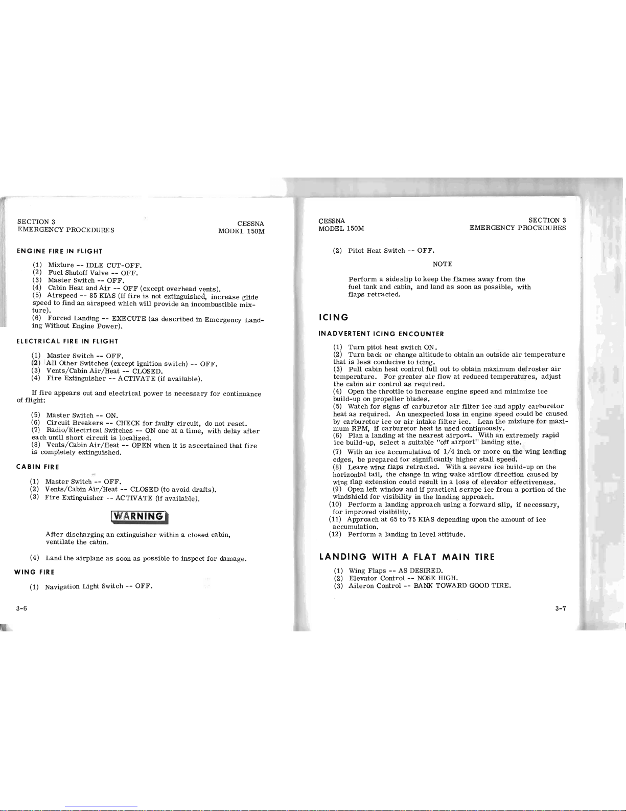
ENGINE
FIRE
IN
FLIGHT
(1)
Mixture --IDLE
CUT-OFF.
(2)
Fuel
Shutoff Valve --OFF.
(3)
Master
Switch --OFF.
(4) Cabin
Heat
and
Air --OFF
(except
overhead
vents).
(5)
Airs~eed
--
85 KIAS
(If
fire
is
not
extinguished,
increase
glide
speed
to
fmd
an
airspeed
which
will
provide
an
incombustible
mix-
ture).
(6)
Forced
Landing --EXECUTE
(as
described
in
Emergency
Land-
ing
Without
Engine
Power).
ELECTRICAL
FIRE
IN
FLIGHT
(1)
Master
Switch --OFF.
(2)
All
Other
Switches
(except
ignition
switch) --OFF.
(3)
Vents/Cabin
Air/Heat --CLOSED.
(4)
Fire
Extinguisher --ACTIVATE
(if
available).
If
fire
appears
out
and
electrical
power
is
necessary
for
continuance
of
flight
:
(5)
Master
Switch --ON.
(6)
Circuit Breake
r s --CHECK
for
faulty
circuit,
do
not
reset.
(7)
Radio/Electrical Sw
itch
es --ON o
ne
at a time, with
delay
after
each
until
sho
rt
circuit
is
loca
lized.
(8)
Vents/Cabin
Air/Heat --OPE
N when
it
is
ascertained
that
fire
is
completely
extinguishe
d.
C
ABIN
FIRE
(1)
Master
Switch --O
FF.
(2)
Vents/Cabin
Air/Heat --CLOSED
(to
avoid
drafts).
(3)
Fire
Extinguisher --ACTIVATE (if
available).
IWARNING '
After
discharging
an
extinguisher
within a closed
cabin,
ventilate
the
cabin.
(4)
Land
the
airplane
as
soon
as
possible
to
inspect
for
damage.
WING
FIRE
(1)
Navigation
Light
Switch --OFF.
3-6
CESSNA
MODEL 150M
SECTION 3
EMERGENCY PROCEDURES
(2)
Pitot
Heat
Switch --OFF.
ICING
NOTE
Perform a sideslip
to
keep
the
flames
away
from
the
fuel
tank
and
cabin,
and
land
as
soon
as
pOSSible,
with
flaps
retracted.
INADVERTENT
ICING
ENCOUNTER
(1)
Turn
pitot
heat
switch
ON.
(2)
Turn
back
or
change
altitude
to
obtain
an
outside
air
temperature
that
is
less
conducive
to
icing.
(3)
Pull
cabin
heat
control
full
out
to
obtain
maximum
defroster air
temperature.
For
greater
air
flow
at
reduced
temperatures,
adjust
the
cabin
air
control
as
required.
(4) Open
the
throttle
to
increase
engine
speed
and
minimize
ice
build-up
on
propeller
blades.
(5)
Watch
for
signs
of
carburetor
air
filter
ice
and
apply
carburetor
heat
as
required.
An
unexpected
loss
in
engine
speed
could
be
caused
by
carburetor
ice
or
air
intake
filter
ice.
Lean
the
mixture
for
maxi-
mum
RPM,
if
carburetor
heat
is
used
continuously.
(6)
Plan a landing
at
the
nearest
airport.
With
an
extremely
rapid
ice
build-up,
select a suitable
"off
airport"
landing
site.
(7) With
an
ice
accumulation
of
1/4
inch
or
more
on
the
wing
leading
edges,
be
prepared
for
significantly
higher
stall
speed.
(8)
Leave
wing
flaps
retracted.
With a
severe
ice
build-up
on
the
horizontal
tail,
the
change
in
wing
wake
airflow
direction
caused
by
wing
flap
extension
could
result
in a loss
of
elevator
effectiveness.
(9)
Open
left
window
and
if
practical
scrape
ice
from a portion
of
the
windshield
for
visibility
in
the
landing
approach.
(10)
Perform a landing
approach
using a forward
Slip,
if
necessary,
for
improved
visibility.
(11)
Approach
at
65
to
75 KIAS
depending
upon
the
amount
of
ice
accumulation.
(12)
Perform a landing
in
level
attitude.
LANDING
WITH
A FLAT
MAIN
TIRE
(1) Wing
Flaps --AS DESIRED.
(2)
Elevator
Control --NOSE HIGH.
(3)
Aileron
Control --BANK
TOWARD GOOD
TIRE.
3-7

SECT
ION . .S
EMERGENCY PROCEDURES
CESSNA
MODEL 150M
(4) Rudd
er
Control --
AS REQUIRED
to
keep nose
straight.
(5) Touchdown --GOOD TIRE
FIRST
, hol d
air
pla
ne
off
flat
tire
as
long
as possible
.
ELECTRICAL
POWER
SUPPLY SYSTEM
MALFUNCTIONS
OVER-VOLTAGE
LIGHT
ILLUMINATE
S
(1) Mast
er Swit
ch - - OF F (both sid
es ).
(2) Mas
te
r S
witch --ON.
(3)
Over-Voltage
Lig
ht --O
FF.
If
over-v
olt
age lig
ht
ill
uminates
again:
(4) F
light --
TERMINATE
as
soon as pra
cti
cal.
AMMETER SHOWS
DISCHARGE
3-8
(1) Alternator --OFF
.
(2) Noness
enti
al
Electric
al Eq
uipment
- -
OFF.
(3)
Fligh
t - -TERMINATE as
soon
as practical.
CESSNA
MODEL 150M
SECTION 3
EMERGENCY PROCEDURES
AMPLIFIED PROCEDURES
ENGINE
FAILURE
If
an
engine
failure
occurs
during
the
takeoff
run,
the
most
importa
nt
thing
to
do
is
stop
the
airplane
on
the
remaining
runway.
Those
extra
ite
ms
on
the
checklist
will
provide
added
safety
during a failure
of
this
type.
Prompt
lowering
of
the
nose
to
maintain
airspeed
and
establish a glide
attitude
is
the
first
response
to
an
engine
failure
after
takeoff.
In
most
cases,
the
landing
should
be
planned
straight
ahead
with
only
small
changes
in
direction
to
avoid
obstructions.
Altitude
and
airspeed
are
seldom
suf-
ficient
to
execute
a 1800 gliding
turn
necessary
to
return
to
the
runway.
The
checklist
procedures
assume
that
adequate
time
exists
to
secure
the
fuel
and
ignition
systems
prior
to
touchdown.
After
an
engine
failure
in
flight,
the
best
glide
speed
as
shown
in
Fig-
ure
3-1
should
be
established
as
quickly
as
possible.
While
gliding
to-
ward a suitable
landing
area,
an
effort
should
be
made
to
identify
the
cause
of
the
failure.
If
time
permits,
an
engine
restart
should
be
attempted
as
shown
in
the
checklist.
If
the
engine
cannot
be
restarted, a forced
landing
without
power
must
be
completed.
12,000
I-
10,000
LL
Z
<t:
8000
a:
a:
w
I-
w
6000
>
0
OJ
<t:
4000
l-
I
CJ
w
2000
I
0
* SPEED
60
KIAS
I---
~~-+---+---+-I
* PROPELLER
WINDMILLING
* FLAPS UP *
ZERO
WIN
D
0 2
4
6
8
10
12
14
16 18
GROUND DISTANCE -
NAUTICAL
MILES
Figure
3
-1.
Maximum
Glide
20
3-9

SECTION 3
EMERGENCY PROCEDURES
FORCED
LANDINGS
CESSNA
MODEL 150M
If
all
attempts
to
restart
the
engine
fail
and a forced
landing
is
immi:'
nent,
select a suitable
field
and
prepare
for
the
landing
as
discussed
in
the
checklist
for
engine
off
emergency
landings.
Before
attempting
an
"off
airport"
landing
with
engine
power
avail-
able,
one
should
drag
the
landing
area
at a safe
but
low
altitude
to
inspect
the
terrain
for
obstructions
and
surface
conditions,
proceeding
as
dis-
cussed
under
the
Precautionary
Landing
With
Engine
Power
checklist.
Prepare
for
ditching
by
securing
or
jettisoning
heavy
objects
located
in
the
baggage
area
and
collect
folded
coats
or
cushions
for
protection
of
occupants I face
at
touchdown.
Transmit
Mayday
message
on
121. 5 MHz
giving
location
and
intentions.
L
ANDING
WITHOUT
ELEVAT
OR
CONT
ROL
Trim
for
horizontal
flight
(with
an
airsp
eed
of
approximately
55 KIAS
and
flaps
lowered
to
20°) by
using
throttle and ele
vat
or
trim
controls.
T
hen
do
not
chan
ge
the
elevator
trim
cont
rol
setting;
cont
rol
the
glide
angle
by
adjusting
power
exclusively.
At
flareout,
the
nose-down
moment result
ing f
rom
power
reduction
is
an adver
se
factor
and
the
airplane
may
hit
on the
nose
wheel.
Conse-
q
uently,
at
flareout,
the
trim
control should
be set
at
the
full
nose-up
p
osition
and
the
power
adjusted
so
tha
t t
he
airpl
ane w
ill
rotate
to
the
hor-
i
zontal
attitude
for
touchdown.
Clos
e the
throttle
at
touchdown.
FIRES
Although
engi
ne
fires
are
extrem
ely rare
in
flig
ht, t
he
steps
of
the
ap
propriate
checklist
should
be
followed
if
o
ne
is e
ncountered.
After
com
pletion
of
this
procedure,
execute a forced
landing.
The
initial
indication
of
an
electrical
fir
e is u
sually
the
odor
of
burn-
i
ng
insulation. The ch
ecklist for
this problem should
result
in
elimination
of
the
fire.
E
MERGENCY
OPE
RATION
IN CLOU
DS
(
Vacuum
Syste m
Failure)
In the
eve
nt
of a
vacuum
system
failure
during
flight
in
marginal
3-10
CESSNA
MODEL 150M
SECTION 3
EMERGENCY PROCEDURES
w~ather
,
the
directional
indicator
and
attitude
indicator will
be
disab
led,
and
the
pilot will
have
to
rely
on
the
turn coordinator
or
the
turn and b
ank
indicator
if
he
inadvertently
flies
into
clouds
. The following
ins
tructions
assume
that
only
the
electrically-powered
turn
coordinator
or
the
tur
n
and
bank
indicator
is
operative,
and
that
the
pilot
is
not
completely
pro
-
ficient
in
instrument
flying.
EXECUTING A 1
80
° TURN
IN
CLOUDS
Upon
inadvertenly
entering
the
clouds,
an
immediate
plan should
be'
made
to
turn
back
as
follows:
(1)
Note
the
time
of
the
minute
hand
and
observe
the position
of
the
sweep
second
hand
on
the
clock.
(2) When
the
sweep
seco
nd
hand
indicates
the
nearest
half-minut
e
initiate a standard rate
left
tur
n, holding t he
turn coordinator
sym
~
bolic
airplane
wing
opposite
the
lower left index mark
for 60
second
::>.
Then
roll
back
to
level
flight
by
leveling
the
miniature
airplane.
(3) Check
accuracy
of
the
turn
by
observing
the
compass
heading
which
should
be
reciprocal
of
the original
heading.
(4)
If
necessary,
adjust
heading
primarily
with
skidding
motions
rather
than
rolling
motions
so
that
the
compass
will
read
more
ac-
curately.
(5)
Maintain
altitude
and
airspeed
by
cautious
applicatio
n of
elevator
control.
Avoid
overcontrolling
by
keeping
the
hands
off
the
control
wheel
and
steering
only
with
rudder.
EME
RGENCY DESCENT THROUGH C
LOUDS
If
conditions
preclude
reestablishment
of
VFR
flight
by a 180°
turn,
a
d
esc
ent
through a cloud
deck
to
VFR
conditions
may
be
appropriate.
If
pos
sible, obtain
radio
clearance
for
an
emergency
descent
through
clouds.
To
guard
against a spiral
dive,
choose
an
easterly
or
westerly
heading
to
minimize
compass
card
swings
due
to
changing bank
angles.
In
addition,
kee
p h
ands
off
the
control
wheel
and
steer a straight
course
with
rudder
contro
l by
monitoring
the
turn
coordinator.
OccaSionally
check
the
com-
pass heading
and
make
minor
corrections
to
hold
an
approximate
course.
Be
fore desce
nding
into
the
clouds,
set
up a
stabilized
let-down
condition
as
follows:
(1) Ap
ply
full
rich mixture.
(2)
Use full car
buretor
heat.
(3)
Reduce
power
to
set
up
a 500
to
800
ft/min
rate
of
descent.
(4)
Adjust the
elev
ator trim
for a stabilized
descent
at
70 KIAS .
(5)
Keep hands
off co
ntrol
wheel.
(6)
Monitor
turn coordinator
and
make
corrections
by
rudder alone.
3-11
SECTION
3
EMERGENCY
PROCEDURE
S
CESSNA
MODEL
150M
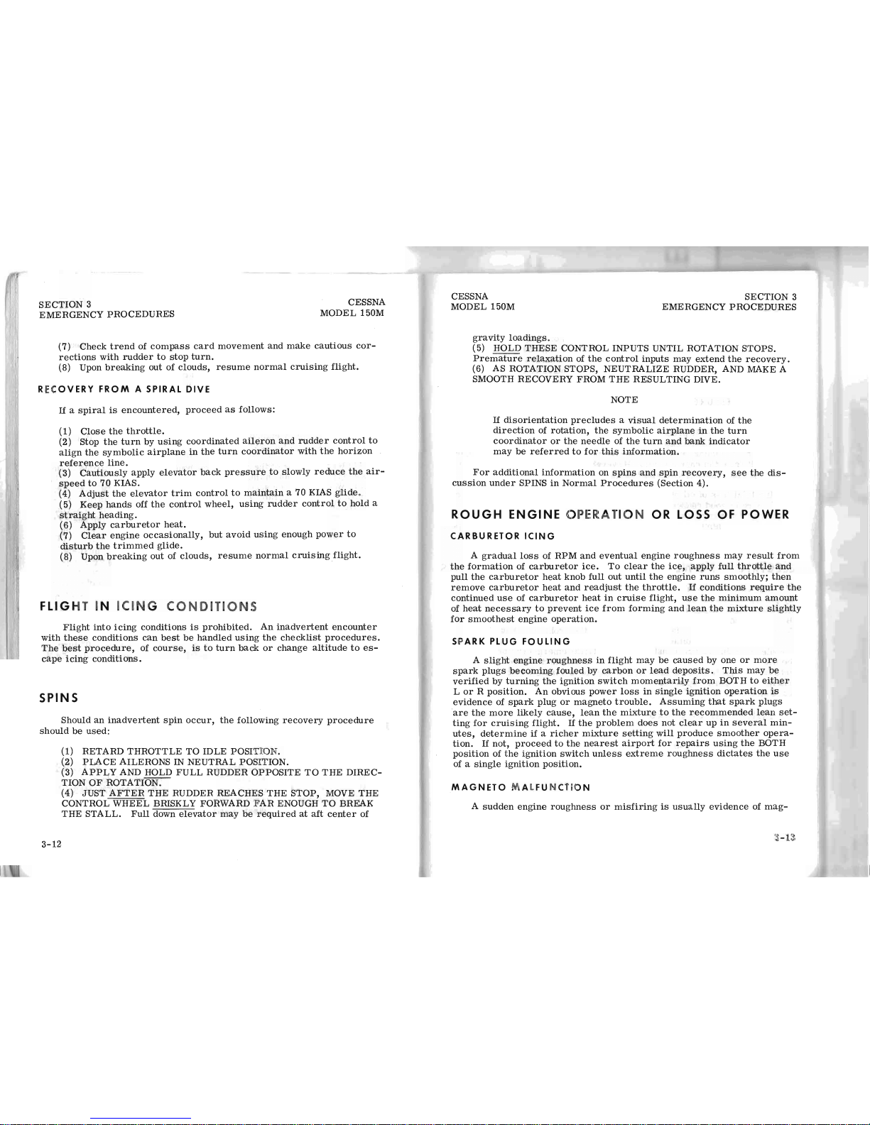
(7)
Check
trend
of
compass
card
movement and
make
cautious
cor-
rections
with
rudder
to
stop
turn.
(8) Upon
breaking
out
of
clouds,
resume
normal
cruising
flight.
RECOVERY
FROM A SPIRAL DIV E
If
a
spiral
is
encountered,
proceed
as
follows:
(1)
Close
the
throttle.
(2) Stop
the
turn
by
uSing
coordinated
aileron
and
rudder
control
to
align
the
symbolic
airplane
in
the
turn
coordinator
with
the
horizon
reference
line.
(3)
Cautiously
apply
elevator
back
pressure
to
slowly
reduce
the
air-
speed
to
70 KIAS.
(4)
Adjust
the
elevator
trim
control
to
maintain
a 70 KIAS
glide
.
(5)
Keep
hands
off
the
control
wheel,
using
rudder
control
to
hold
a
straight
heading.
(6) Apply
carburetor
heat.
(7)
Clear
engine
occasionally,
but
avoid
using
enough
power
to
disturb
the
trimmed glide.
(8) Upon
breaking
out
of
clouds,
resume
normal
cruisingflight.
FLI
GHT
IN
ICING
CONDITIONS
Flight
into
icing
conditions
is
prohibited.
An
inadvertent
encounter
with
these
conditions
can
best be
handled
using the
checklist
procedures.
The
best
procedure,
of
course,
is
to
turn
back
or
change
altitude
to
es-
cape
icing
conditions.
SPIN
S
Should
an
inadvertent
spin occur,
the
foll
owing
recovery
procedure
should
be
used:
3-12
(1)
RETARD
THROTTLE
TO
IDLE
POSITION.
(2)
PLACE
AILERONS IN NE
UTRAL
POSITION.
(3) AP
PLY
AND HOLD
FUL
L RUDDER OPPOSITE
TO
THE
DIREC-
TION
OF
ROTATION.
(4) JUST A
FTER THE
RUDD
ER
REACHES THE
STOP,
MOVE
THE
CONTROL WHEEL BRISKLY FORWA RD
FAR
ENOUGH TO BREAK
THE
STALL. Full down elevator
may
be
required
at
aft center
of
CESSNA
MODEL 150M
SECTION 3
EMERGENCY
PROCEDURES
gravity
loadings.
(5) HOLD
THESE
CONTROL INPUTS UNTIL ROTATION STOPS.
Premature
relaxation
of
the
control
inputs
may
extend
the
recovery.
(6) AS ROTATION STOPS,
NEUTRALIZE
RUDDER, AND MAKE A
SMOOTH RECOVERY FROM
THE
RESULTING DIVE.
NOTE
If
disorientation
precludes a visual
determination
of
the
direction
of
rotation,
the
symbolic
airplane
in
the
turn
coordinator
or
the
needle
of
the
turn
and
bank
indicator
may
be
referred
to
for
this
information.
For
additional
information
on
spins
and
spin
recovery,
see
the
dis-
cussion
under
SPINS
in
Normal
Procedures
(Section
4).
ROUGH
ENGINE
OPERATION
OR LOSS OF
POWER
CARBURETOR
ICING
A
gradual
loss
of
RPM
and
eve
ntu
al
engine
roughness
may
result
from
the
formation
of
carburetor
ice.
To
clear
the
ice,
apply
full
throttle
and
pull
the
carburetor
heat
knob
full out
until the
engine
runs
smoothly;
then
remove
carburetor
heat
and
readjust
the
throttle.
If
conditions
require
the
continued
use
of
carburetor
heat
in
crui
se
flight,
use
the
minimum
amount
of
heat
necessary
to
prevent
ice
from
forming
and
lean
the
mixture
slightly
f
or
smoothest
engine
operation.
SPA RK
PLUG
FOULING
A
slight
engine
roughness
in
flight
may
be
caused
by
one
or
more
spark plugs
becoming
fouled
by
carbon
or
lead
deposits.
This
may
be
verified
by
turning
the
ignition
switch
momentarily
from
BOTH
to
either
L
or
R pOSition.
An
obvious
power
loss
in
Single
ignition
operation
is
evidence
of
spark
plug
or
magneto
trouble.
Assuming that
spark
plugs
are
the
more
likely
cause,
lean
the
mixture
to
the
recommen
ded
lean
set-
ting
for
cruising
flight.
If
the
problem
does
not
clear
up
in
several
min-
utes,
determine
if
a
richer
mixture
setting
will
produce
smoother
opera-
tion.
If
not,
proceed
to
the
nearest
airport
for
repairs
using
the
BOTH
pOSition of
the
ignition
switch
unless
extreme
roughness
dictates
the
use
of a
single igniti
on
position.
M A
GNETO MALF
U N C
TIO
N
A
sudden
engine rou
ghness
or
mis
fir
ing
is usu
all
y e
vidence
of
mag-
3-13

SECTION 3
EMERGENCY PROCEDURES
CESSNA
MODEL
150M
neto
problems.
Switching
from
BOTH
to
either L or R ignition
switch
position
will
identify
which
magneto
is
malfunctioning.
Select
different
power
settings
and
enrichen
the
mixture
to
determine
if
continued
opera-
tion
on BOTH
magnetos
is
practicable.
If
not,
switch
to
the
good
magneto
and
proceed
to
the
nearest
airport
for
repairs.
LO W OIL PRESSURE
If
low oil
pressure
is
accompanied
by
normal
oil
temperature,
there
is a possibility
the
oil
pressure
gage
or
relief
valve
is
malfunctioning.
A
leak
in
the
line
to
the
gage
is
not
necessarily
cause
for
an
immediate
precautionary
landing
because
an
orifice
in
this
line
will
prevent a sudden
loss
of
oil
from
the
engine
sump.
However, a landing
at
the
nearest
air-
port
would
be
advisable
to
inspect
the
source
of
trouble.
If
a
total los
s of oil
pressure
is
accompanied
by a
rise
in
oil
tempera-
ture,
there
is
good
reason
to
suspect
an
engine
failure
is
imminent.
Re-
duce
engine
power
immediately
and
select a suitable
forced
landing
field.
Use
only
the
minim
um
power
required
to
reach
the
desired
touchdown
spot.
ELECT
RICAL
POWER SUPP
LY SYSTEM
MALFUNCTIONS
Malfunctions
in
the ele
ctrical power supply
system
can
be
detected
by
periodic
monitoring
of
the
ammet
er and over
-voltage
warning
light;
however,
the
cause
of
these
malfunctions
is
usually
difficult
to
determine.
Broken
or
loose
alternator
wiring
is
most
likely the
cause
of
alternator
failures,
alt
hough
other
factors could
cause
the
problem. A damaged
or
improperly
adjusted
voltage
regulator
can
also
cause
malfunctions.
Problems
of
this
nature
constitute
an
electri
cal
emergency
and
should
be
dealt
with
immediately.
Electrical
power
malfunctions
usually
fall
into
two
categories:
excessive
rate
of
charge
and
insufficient
rate
of
charge.
The
paragraphs
below
describe
the
recommended
remedy
for
each
situation.
EXCESSIV E RATE OF
CHARGE
After
engine
starting
and
heavy
electrical usage
at
low
engine speeds
(such
as
extended
taxiing)
the
battery
condition will
be
low
enough
to
ac-
cept
above normal
charging
during
the
initial
par
t of a
flight.
However,
after
thirty
minutes
of
cruising
flight,
the
ammeter
should
be indicating
less
than
two
needle
widt
hs
of
char
ging
current.
If
the
charging
rate were
to
remain
above
this
value
on a long flight,
the battery
would
overheat
and
evapora
te
the
electrolyte
at
an
excessive
rate. Electronic
components
in
the electrical
system
could be
adversely
affected
by
higher
than
normal
3-
14
CESSNA
MODEL 150M
SECTION 3
EMERGENCY PROC EDURES
voltage
if
a
faulty
voltage
regulator
setting
is
caUSing
the
overc
harging.
To
preclude
these
pOSSibilities,
an
over-voltage
sensor
will automati
..
cally
shut
down
the
alternator
and
the
over-voltage
warning
light
will
illuminate
if
the
charge
voltage
reaches
approximately
16
volts. Assum-
ing
that
the
malfunction
was
only
momentary,
an
attempt
should
be
made
to
reactivate
the
alternator
system.
To
do
this,
turn
both
sides
of t he
master
switch
off
and
then
on
again.
If
the
problem
no
longer
exists,
normal
alternator
charging
will
resume
and
the
warning
light
will
go off.
If
the
light
comes
on
again, a malfunction
is
confirmed.
In
this
event,
t
he
flight
should
be
terminated
and/or
the
current
drain
on
the
batte
ry
minimized
because
the
battery
can
supply
the
electrical
system
for
only
a
limited
period
of
time.
If
the
emergency
occurs
at
night,
power
must
be
conserved
for
later
use
of
the
landing
light
and
flaps
during landing.
I
NSUFF
ICIENT
RATE OF C
HARGE
If
the
ammeter
indi
cates
a con
tinuous
discharge
rate
in
flight,
the
alt
ernator
is
not
sup
plyin
g pow
er
to
the
system
and
should
be
shut
down
since
the
alternator
field
circuit may
be
pla
cing
an
unnecessary
load
on
the
system.
All
nonessential equipment should be
turned
off and
the
fligh
t
t
erminated
as
soon
as
practica
l.
3-15/(3-16 blank)

CESSNA
MODEL
150M
SEC
TION 4
NORMAL
PROCEDURES
S
EC1
-ION 4
NORMAL
PRO
CEDU
RES
TA B
LE
OF
CONTENTS
Introduction
. . . . . . .
Speeds
For
Safe
Operation
Preflight
Inspection
Cabin
.....
Empennage
CHECK LI
ST
~ROC
EDURES
Right
Wing,
Trailing
Edge
Right
Wing
Nose ...
...
. . .
Left
Wing
....
..
.
Left
Wing,
Leading
Edge
Le
ft
Wing,
Trailing
Edge
Be
fore
Starti
ng
Engine
St
arting
Engine
Before
Takeoff
Takeoff ....
N
ormal
Takeoff
Maximum
Performance
Takeoff
Enrout
e C
limb
.
Crui
se
....
Bef
ore Landin
g
Ba
lk
ed
Land
ing
Normal
Landing
After Lan
din
g .
Secur
ing
Air
pla
ne
S
tarti
ng
Engine
Tax
iing ....
AMP
LIFIED
PRO
CE DURES
Page
4-3
4-3
4-5
4-5
4-5
4-5
4-5
4-5
4":6
4-6
4-6
4-6
4-7
4-7
4-7
4-7
4-8
4-8
4-8
4- 8
4
-8
4-9
4-9
4-9
4-
11
4-11
4-
1

SECTION
4
NORMAL
PROCED
URES
TABLE
O F C
ONTENTS
(Continued)
Before
Tak
eoff . . . .
War
m-U
p . . . .
Ma
gn
eto Check
. .
Alternator Check
.
Tak
eoff ...
.
..
.
Pow
er Check
F
lap
Settings
.
M
aximum
Performan
ce T
akeof
f
Crosswind
Takeo
ff
Enr
oute
Climb
. . .
Nor
mal
Climb
. .
Best
Rate
Climb
.
Be
st Angle
Climb
Cruise
Stall
s .
Spins
.
Landing
Sho
rt
Field
Landin
g
Crosswind
Lan
ding .
Balked
Landi
ng
Cold
Weather
Oper
ati
on.
Noise
Abatement
. . . .
4-2
CESSNA
MODEL 150M
Page
4-13
4-1
3
4-13
4-13
4-
13
4-1
3
4-14
4
-14
4-14
4-1
5
4-1
5
4- 15
4-15
4-1
5
4-17
4-17
4-19
4-19
4-20
4-20
4-20
4-22
CESSNA
MODEL 150M
IN
TRODUCTION
SECTION 4
NORMA L P ROCE DURES
Section 4 provides
checklist
and
amplified
procedures
for
the
conduct
of
normal
operation.
Normal
procedures
associated
with
Optional Sys-
tems
can
be
found
in
Section
9.
SPEEDS
FOR
SAFE
OPERATION
Unless
otherwise
noted,
the
following
speeds
are
based
on a maxi-
mum
weight
of 1600
pounds
and
may
be
used
for
any
lesser
weight.
Takeoff:
Normal
Climb
Out
Maximum
Performance
Takeoff,
Speed
at
50
Feet.
Climb,
Flaps
Up:
Normal
...
Best
Rate
of
Climb,
Sea Leve
l .
Best
Rate
of
Climb,
10, 000
Feet
Best
Angle
of
Climb,
Sea
Lev
el
thru
10,000
Feet
.....
Landing
Approach:
Normal
Approach,
Flaps
Up
.
Normal
Approach,
Flaps
40° .
Short
Field
Approach,
Flaps
40°
Balked
Landing:
During
Transition
to
Maximum Power,
Flaps
20°
Maximum
Recommended
Turbulent
Air Penetration
Speed
1600
Lbs ...
.........
. .
1450
Lbs
.......
......
.
1300
Lbs
.............
.
Maximum
Demonstrated
Crosswind Velocit
y
Takeoff
Landing
.....
.. ..
...
..
.
60-70
KIAS
"=
~
. . 60 KIAS
65-75
KIAS
68
RJA
S
62
KIAS
56
KIAS
60-70
KIAS
50-60
KIAS
52
KIAS
55 KIAS
97 KIAS
93 KIAS
88 KIAS
13 KNOTS
13 KNOTS ·
4-3

SECTION
4
CESSNA
MODEL 150M
NORMAL PROCEDURES
4-4
NOTE
Visually
check
airplane
for
general
condition
during
walk-around
inspection.
In
cold weather,
remove
even
small
accumulations
of
fros
t,
ice
or
snow
from
wing,
tail
and
control
surfaces. Also,
make
sure
that
control
surfaces
contain
no
internal
accumula-
tions
of
ice
or
debris.
If
a
night
flight
is
planned,
check
operation
of
all
lights,
and
make
sure a flash-
light
is
available.
Figure
4-1.
Preflight
Inspection
CESSNA
MODEL 150M
SECTION
4
NORMAL
PR
OCEDURES
CHECKLIST
PROCEDURES
PR
EFLIGHT
INSPECTION
CD
CABIN
(1)
Control
Wheel
Lock --REMOVE.
(2)
Ignition
Switch --OFF.
(3)
Master
Switch --ON.
(4)
Fuel
Quantity
Indicators --CHECK QUANTITY.
(5)
Master
Switch --OFF.
(6)
Fuel
Shutoff Val
ve --ON.
®
EMPENNAGE
(1)
Rudder
Gust
Lock --REMO
VE.
(2)
Tail
Tie-Down
- - DISCONN
ECT
.
(3)
Control
Surfaces --CHECK
freedom
of
movement and
security.
o
RIGHT
WING
Trailing
Edge
(1)
Aileron --CHECK
freedom
of
movement
and
security.
o RI G HT
WING
(1) Wing
Tie-Down
-- DISCONNECT.
(2)
Main
Wheel
Tire --CHECK
for
proper
inflation
(3)
Before
first
flight
of
the
day
and
after
each
refueling,
use
sampler
cup
and
drain
small
quantity
of
fuel
from
fuel
tank
sump
quick-drain
valve
to
check
for
water,
sediment,
and
proper
fuel
grade
(red).
(4)
Fuel
Quantity --CHECK VISUALLY
for
desired
level.
(5)
Fuel
Filler
Cap --SECURE.
®
NO
SE
(1)
Engine Oil
Level --CHECK, do not
operate
with
less
than
four quarts.
Fill
to
six
quarts
for
extended
flight.
(2) Be
fore
first
flight
of
the
day
and
after
each
refueling,
pull
out
strain
er
drain
knob
for
about
four
seconds
to
clear
fuel
strainer
of
possible
water
and
sediment.
Check
strainer
drain
closed.
If
water
is
observed,
the
fuel
system
may
contain
additional
water,
and
further
draining
of
the
system
at
the
strainer,
fuel
tank
sumps,
and
fuel
line
drain
plug
will
be
necessary.
4-5

SECTION
4
CESSNA
MODEL
150M
NORMAL
PROCEDURES
(3)
Propeller
and
Spinner --CHECK
for
nicks
and
security.
(4)
Carburetor
Air
Filter --CHECK
for
restrictions
by
dust
or
other
foreign
matter.
(5)
Landing
Light(s)
- - CHECK
for
condition
and
cleanliness.
(6)
Nose
Wheel
Strut
and
Tire --CHECK
for
proper
inflation.
(7)
Nose
Tie-Down --DISCONNECT .
(8)
Static
Source
Opening
(left
side
of
fuselage) --CHECK
for
stoppage.
® LEFT
WING
(1)
Main
Wheel
Tire --CHECK
for
proper
inflation.
(2)
Before
first fligh
t of day
and
after
each
refueling,
use
sampler
cup
and
drain
small
quantity
of
fuel
from
fuel
tank
sump
quick-drain
valve
to
check
for
water,
sediment
and
proper
fuel
grade
(red).
.
(3)
Fuel
Quantity --CHECK VISUALLY
for
desired
level.
(4)
Fuel
Filler
Cap --SECURE.
o
LEFT
WIN
G Le a
ding
Edge
(1)
Pitot Tube
Cover --REMOVE
and
check
opening
for
stoppage.
(2 )
Stall
Warning
Opening --CHECK
for
stoppage.
To
check
the
system,
place a clean
handkerchief
over
the
vent opening
and
apply
suctio
n; a
sound
from
the
warni
ng
horn wi
ll
confirm
sys-
tem
operation.
(3)
Fuel
Tank
vent
Opening --CHE
CK for
stoppage.
(4) Wing
Tie
Down --DISCONNECT.
® LEFT
WING
Trailing
Edge
(1)
Aileron --CHECK
freedom
of
movement and
security.
BEFORE
STARTING
ENGIN
E
4-6
(1)
Preflight
Inspection --COMPLETE.
(2)
Seats,
Belts,
Shoulder
Harnesses --ADJUST
and
LOCK.
(3)
Fuel
Shutoff
Valve --ON.
(4)
Radios,
Electrical
Equipment --OFF.
(5)
Brakes --TEST
and
SET.
(6)
Circuit
Breakers --CHECK IN.
CESSNA
MODEL
150M
SECTION 4
NORMAL PROCEDURES
STARTING
ENGINE
(1)
Mixture --RICH.
(2)
Carburetor
Heat --COLD.
(3)
Master
Switch --ON.
(4)
Prime --AS REQUIRED.
(5)
Throttle --OPEN
1/4
INCH.
(6)
Propeller
Area --CLEAR.
(7)
Ignition
Switch --START
(release
when
engine
starts).
(8)
Oil
Pressure --CHECK.
BEFORE
TAKEOFF
.
(1)
Cabin
Doors --CLOSED
and
LATCHED.
(2)
Flight
Controls --FREE
and
CORRECT.
(3)
Elevator
Trim --TAKEOFF.
(4)
Flight
Instruments --SET.
(5)
Radios --SET.
(6)
Fuel
Shutoff
Valve --ON.
(7)
Mixture --RICH
(below
5000
feet).
(8)
Parking
Brake --SET.
(9)
Throttle --1700
RPM.
a.
Magnetos --CHECK
(RPM
drop
should
not
exceed
150
RPM
on
either
magneto
or
75
RPM
differential
between
magnetos).
b.
Carburetor
Heat --CHECK
(for
RPM
drop).
c.
Engine
Instruments
and
Ammeter --CHECK.
d.
Suction
Gage
--
CHECK. J
(10)
Flashing
Beacon,
Navigation
Lights
And/Or
strobe
J,
Lights --ON
as
required.
(11)
Throttle
Friction
Lock --ADJUST.
0:<)
1~a.">f0I1r1~",
ON
TAKEOFF
NORMAL
TAKEOFF
(1) Wing
Flaps --0°.
(2)
Carburetor
Heat --COLD.
(3)
Throttle --FULL
OPEN.
(\
\
\
(4)
Elevator
Control -LIFT
NOSE
WHEEL
at
50 KIAS.
(5)
Climb
Speed --60-70
KIAS.
----
4-7

SECTION
4
NORMAL
PROCEDURES
MAXIMUM
PERFORMANCE TAKEOFF
(1) Wing
Flaps --0° .
(2)
Carburetor
Heat --COLD.
(3)
Brakes --APPLY.
(4)
Throttle --FULL
OPEN.
(5)
Brakes --RELEASE.
(6)
Elevator
Control --SLIGHTLY TAIL LOW.
(7)
Climb
Speed --60 KIAS
(With
obstacles
ahead).
E
NROUTE
CLI
MB
(1)
Airspeed --Q.2,;
75
KIAS
.
."
NOTE
CESSNA
MODEL
150M
If
a
maximum
performance
climb
is
necessary,
use
speeds
shown
in
the
Rate
Of
Climb
chart
in
Section
5.
(2)
Throttle --FULL
OPEN.
(3)
Mixture --FULL
RICH
(mixture
may
be
leaned
above
5000
feet).
CRUISE
(1)
Power --2000-2750
RPM
(no
more
than 75%).
(2)
Elevator
T
~ST.
(3)
Mixture --LEAN.
BEFORE
LANDING
(1)
Seats,
Belts,
Harnesses --ADJUST and LOCK.
(2)
Mixture --RICH.
(3)
Carburetor
Heat --ON
(apply
full
heat
before
closing
throttle).
(4)
Airspeed --60-70
KIAS
(flaps
UP).
(5) Wing
Flaps --AS DESIRED O
>clOw 85
KIAS).
(6)
Airspeed --50-60
KIAS
(flaps
DOWN).
BALK
ED
LANDING
4-8
(1)
Throttle --FULL
OPEN.
(2)
Carburetor
Heat --COLD.
CESSNA
MODEL
150M
SECTION
4
NORMAL
PROCEDURES
(3)
Wing
Flaps --RETRACT
TO
20°.
(4)
Airspeed --55 KIAS.
(5)
Wing
Flaps --RETRACT
SLOWLY.
NORMAL
LANDING
(1)
Touchdown --MAIN
WHEELS
FIRST.
(2)
Landing
Roll --LOWER NOSE
WHEEL
GENTLY.
(3)
Braking --MINIMUM REQUIRED.
AFTER
LANDING
(1)
Wing
Flaps --UP.
(2)
Carburetor
Heat
- - COLD.
SECURING
AIRPL
A NE
(1)
Parking
Brake --SET.
(2) RadiOS,
Electrical
Equipment --OFF.
(3)
Mixture --IDLE
CUT-OFF
(pull
full
out).
(4)
Ignition
Switch --OFF.
(5)
Master
Switch --OFF.
(6)
Control
Lock --INSTALL.
4-9/(4-10
blank)

CESSNA
MODEL 150M
SECTION 4
NORMAL PROCEDURES
AMIPLIFIED
PROCEDURES
STARTING
ENGINE
Ordinarily
the
engine
starts
easily
with one
or
two
strokes
of
primer
in
warm
temperatures
to
six
strokes
in
cold
weather,
with
the
throttle
open
approximately
1/4
inch.
In
extremely
cold
temperatures,
it
may
be
necessary
to
continue
priming
while
cranking.
Weak
intermittent
firing
followed by puffs of
black
smoke
from
the
exhaust
stack
indicate
over'priming
or
flooding.
Excess
fuel
can
be
cleared
from
the
combustion
chambers
by
the
following
procedure:
Set
mixture
control
in
the
idle
cut-off
position,
throttle
full
open,
and
crank
the
engine
through
several
revolutions
with
the
starter.
Repeat
the
start-
ing
procedure
without any
additional
priining.
If
the
engine
is
underprimed
(most
likely
in
cold
weather
with a cold
engine)
it
will
not
fire
at
all,
and
additional
priming
will
be
necessary.
As
soon
as
the
cylinders
begin
to
fire,
open
the
throttle
slightly
to
keep
it
running.
After
starting,
if
the
oil gage
does
not
begin
to
show
pressure
within
30
seconds
in
the
summertime
and
about
twice
that
long
in
very
cold
weather,
stop
engine
and
investigate.
Lack
of
oil
pressure
can
cause
serious
engine
damage.
After
starting,
avoid
the
use
of
carburetor
heat
unless
icing
conditions
prevail.
TAXIING
When
taxiing,
it
is
important
that
speed
and
use
of
brakes
Le
held
to
a
minimum
and
that
all
controls
be
utilized
(see
Taxiing
Diagram,
Figure
4-2)
to
maintain
directional
control
and
balance.
The
carburetor
heat
control
knob
should
be
pushed full
in
during
all
ground
operations
unless
heat
is
absolutely
ne
cessary.
When
the
knob
is
pulled
out
to
the
heat
position,
air
entering
the
engine
is
not
filtered.
Taxiing
over
loose
gravel
or
cinders
should
be done
at
low engine
speed
to
avoid
abrasion
and
stone
damage
to
the
propeller
tips.
The
nose
wheel
is
designed
to
automatically
center
straight
ahead
when
the
nose
strut
is
fully extended.
In
the
event
the
nose
strut
is
over
-
4-11

SECTION.4
NORMAL PROCEDURES
CODE
WIND
DIRECTION
•
NOTE
CESSNA
MODEL 150M
Strong quartering tail
winds
require cauti
on.
Avo
id
sudden
bursts
of
the
throttl
e a
nd
sharp
braking
when
the
airplane is
in
this
attitude
.
Use
the
steerable nose
whe
el
and
rudd
er to
maintain
direction
.
Figure
4-2.
T
axiing Diagram
4- 12
CESSNA
MODEL 150M
SECTION
4
NORMAL PROCEDURES
inflated
and
the
airplane
is
loaded
to a rearward
center
of
gravity
posi-
tion,
it
may
be
necessary
to
partially
compress
the
strut
to
permit
steer-
ing.
This
can
be
accomplished
prior
to
taxiing
by
depressing
the
airplane
nose
(by hand)
or
during
taxi
by
sharply
applying
brakes
.
BEFORE TAKEOFF
WARM-UP
Most
of
the
warm-up
will
have
been
conducted
during
taxi,
and
add
i-
tional
warm-up
before
takeoff
should
be
restricted
to
the
checklist
proce-
dures.
Since
the
engine
is
clo
sely
cowled
for
efficient
in-flight
cooling
,
precautions
should
be tak
en
to
avoid
overheating
on
the
ground.
MAGNETO
CHE
CK
The
magneto
check
should
be ma
de
at
1700
RPM
as
follows.
Move
ignition
switch
first
to R positio
n and note
RPM.
Next
move
switch
back
to
BOTH
to
clear
the
other
set
of p
lug
s . Th
en
move
switch
to
the L posi-
tion,
note
RPM
and
return
the
switch
to
the
BOTH
position.
RPM
drop
should
not
exceed
150
RPM
on eith
er
magne
to
or
show
greater
than
75
RPM
differential
between
magnetos.
If
there
is
a doubt
concerning
opera-
tion
of
the
ignition
system,
RPM
che
cks
at higher
engine
speeds
will
usually
confirm
whether a deficiency e
xists.
An
absence
of
RPM
drop
may
be an
indication
of
faul
ty g
rounding
of
one
side
of
the
ignition
system
or sho
uld
be
cause
for
susp
icion
that
the
magneto
timing
is
set
in
advance
of
the
setting
spec
ifi
ed.
ALTERNATOR
CHECK
Prior
to
flights
where
verificati
on of proper alternator
and
voltage
regulator
operation
is
essential
(such
as nig
ht
or
instrument
flights),
a
positive
verification
can
be
made
by loading the
electrical
system
momen-
tarily
(3
to 5 se
conds)
with
the landing
ligh
t, or by
operating
the
wing
flaps
during
the
engine
runup
(1700 RPM).
The
amm
eter
will
remain
within
a
needle
width
of
zero
if
the
alternator and volt
age
regulator
are
operating
properiy.
TAKEOFF
POWER
CHE
CK
It
is
important
to
check full-
thr
ottle engine
oper
at ion
early
in the take-
4-13

SECTION
4
NORMAL PROCEDURES
CESSNA
MODEL
150M
off
run.
Any
sign
of
rough
engine
operation
or
sluggish
engine
accelera-
tion
is
good
cause
for
discontinuing
the
takeoff.
If
this
occurs,
you
are
justified
in
making a thorough
full-throttle
static
runup
before
another
takeoff
is
attempted.
The
engine
should
run
smoothly
and
turn
approxi-
mately
2460
to
2560
RPM
with
carburetor
heat
off.
Full
throttle
runups
over
loose
gravel
are
especially
harmful
to
pro-
peller
tips.
When
takeoffs
must
be
made
over a gravel
surface,
it
is
very
important
that
the
throttle
be
advanced
slowly.
This
allows
the
air-
plane
to
start
rolling
before
high
RPM
is
developed,
and
the
gravel
will
be
blown
back
of
the
propeller
rather
than
pulled
into
it.
When
unavoid-
able
small
dents
appear
in
the
propeller
blades,
they
should
be
immediate-
ly
corrected
as
described
in
Section 8 under
Propeller
Care.
Prior
to
takeoff
from
fields
above
5000
feet
elevation,
the
mixture
should
be
leaned
to
give
maximum
RPM
in a full-throttle,
static
runup.
After
full
throttle
is
applied,
adjust
the
throttle
friction
lock
clock-
wise
to
prevent
the
throttle
from
creeping
back
from a maximum
power
position.
Similar
friction
lock
adjustment
should
be
made
as
required
in
other
flight
conditions
to
maintain a fixed
throttle
setting.
flAP
SETTINGS
Normal
and
obstacle
clearance
takeoffs
are
performed
with
flaps
up.
The
use
of 10°
flaps
will
shorten
the
ground
run
approximately
10%,
but
this
advantage
is
lost
in
the
climb
to a 50-foot
obstacle.
Therefore
the
use
of 10°
flaps
is
reserved
for
minimum
ground
runs
or
for
takeoff
from
soft
or
rough
fields.
If
10° of
flaps
are
used
on
soft
or
rough
fields
with
obstacles
ahead,
it
is
preferable
to
leave
them
extended
rather
than
retract
them
in
the
climb
to
the
obstacle.
The
exception
to
this
rule
would
be
in a high
alti-
tude
takeoff
in
hot
weather
where
climb
would
be
marginal
with
flaps
10°.
Flap
deflections
greater
than
10°
are
not
approved
for
takeoff.
MAXIMUM
PERFORMANCE TAKEOFF
If
an
obstruction
dictates
the
use
of a
steep
climb
angle,
after
liftoff
accelerate
to
and
climb
out
at
an
obstacle
clearance
speed
of 60 KIAS
with
flaps
retracted.
This
speed
provides
the
best
overall
climb
speed
to
clear
obstacles
when
taking
into
account
the
turbulence
often
found
near
ground
lev
el.
CROS
SWIND
TAKEOFF
Takeoffs
into
strong
crosswinds
normally
are
performed
with
the
4-14
CESSNA
MODEL 150M
SECTION
4
NORMAL
PROCEDURES
minimum
flap
setting
necessary
for
the
field
length,
to
minimize
the
drift
angle
immediately
after
takeoff.
The
airplane
is
accelerated
to
a
speed
slightly
higher
than
normal,
then
pulled
off
abruptly
to
prevent
possible
settling
back
to
the
runway
while
drifting.
When
clear
of
the
ground,
make a coordinated
turn
into
the
wind
to
correct
for
drift.
ENROUTE
CLIMB
When
conducting
the
following
climbs,
the
mixture
should
be
full
rich
below
5000
feet
and
may
be
leaned,
if
necessary,
above
5000
feet
for
smoother
engine
operation.
NORMAL
CLIMB
Normal
climbs
are
conducted
at
65
to
75
KJAS
with
flaps
up
and
full
throttle
for
best
engine
COOling. ."--
-
BEST
RATE
CLIM
B
The
best
rate
of
climb
speeds
range
from
68 KJAS
at
sea
level
to
62
KIAS
at
10,000
feet
with
flaps
up
and
full
throttle.
BEST
ANGLE
CLIMB
If
enroute
terrain
dictates
the
use
of a
steep
climb
angle,
climb
at
the
best
angle
of
climb
speed
of
56
KIAS
with
flaps
up
and
full
throttle.
NOTE
Steep
climbs
at
low
airspeeds
should
be
of
short
duration
to
allow
improved
engine
COOling.
CRUISE
Normal
cruiSing
is
performed
between
55%
and
75%
power.
The
en-
gine
RPM
and
corresponding
fuel
consumption
for
various
altitudes
can
be
determined
by
using
your
Cessna
Power
Computer
or
the
data
in
Section
5.
NOTE
Cruising
should
be
done
at
65%
to
75%
power
until a total
of 50
hours
has
accumulated
or
oil
consumption
has
sta-
bilized.
This
is
to
ensure
proper
seating
of
the
rings
and
is
applicable
to
new
engines,
and
engines
in
service
4-15

SECTION 4
NORMAL PROCEDURES
CESSNA
MODEL 150M
following
cylinder
replacement
or
top
overhaul
of one
or
more
cylinders
.
The
data
in
Section 5 shows
the
increased
range
and
improved
fuel
economy
that
is
obtainable
when
operating at
lower
power
settings
and
higher
altitudes.
The
use
of
lower
power
settings
and
the
selection
of
cruise
altitude
on
the
basis
of
the
most
favorable
wind
conditions
are
significant
factors
that
should
be
conside
red on
every
trip
to
reduce
fuel
consumption.
The
Cruise
Performance
Table, Figure
4-3,
shows
the
true
airspeed
and
nautical
miles
per
gallon
during
crui
se
for
various
altitudes
and
per-
cent
powers.
This
table
should
be
used
as a
guide,
along with
the
avail-
able
winds
aloft
information,
to
determi
ne the most
favorable
altitude
and
power
setting for a
given
trip.
To
achieve
the
recommended
lean
mixtur
e fu
el
consu
mption
figures
shown
in
Section
5,
the
mixture
should
be lean
ed
as follows:
(1)
Pull
the
mixture
control
out
until engine
RPM
peaks
and
begins
to
fall
off.
(2)
Enrichen sli
ghtly
back
to
peak RPM.
For
best
fuel
economy
at 65% pow
er
or
less,
opera
te at
the
leanest
mixture
that
results
in
smooth
engine operation
or
at
50
RPM
on
the
lean
side
of
the
peak
RPM,
whichever
occurs first.
This will
result
in
approxi-
mately
5%
greater
range
than
shown
in this
handbook.
Carburetor
ice,
as
evidenced
by
an
unexplained drop in RP M,
can
be
removed
by
application
of
full
carburet
or
heat.
Upon regaining
the
orig
i-
nal
RPM
(with
heat
off),
use
the
minimum
amount
of
heat
(by
trial
and
75%
POWER
65% POWER
55%
POWER
ALTITUDE
KTAS NMPG KT AS NMPG KTAS NMPG
Sea
Level
100 17.9 94
19.2
88
21.0
3500 Feet 103 18.4
97 19.8
91
21.7
7000 Feet
106 18.9 100
20.4
94
22.4
Standard Conditions
Zero Wind
Figure
4-3.
Cr u
ise
Per
forman
ce
Table
4- 16
CESSNA
MODEL 150M
SECTION
4
NORMAL PROCEDURES
error)
to
prevent
ice
from
forming.
Since
the
heated
air
causes a richer
mixture,
readjust
the
mixture
setting
when
carburetor
heat
is
to
be
used
continuously
in
cruise
flight.
The
use
of
full
carburetor
heat
is
recommended
during
fli
ght
in
very
heavy
rain
to
avoid
the
possibility
of
engine
stoppage
due
to
excessive
water
ingestion.
The
mixture
setting
should
be
readjusted
for
smoothest
operation.
ST
ALLS
The
stall
characteristics
are
conventional
for
the
flaps
up
and
flaps
down condition.
Slight
elevator
buffeting
may
occur
just
before
the
stall
with
flaps
down.
The
stall
warning
horn
produces a steady
signal 5 to
10
knots
before
the
actual
stall
is
reached
and
remains
on
until
the
airplane
flight
attitude
is
changed. Stall
speeds
for
various
combinations
of
flap
setting
and
bank
angle
are
summarized
in
Section
5.
SPINS
Intentional
spins
are
approved
in
this
ai rplane
(see
Sectio
n 2).
Before
attempting
to
perform
spins,
however,
sever
al
items
should
be
carefully
considered
to
assure a safe
flight.
No spins should
be attempted
without
first
having
received
dual
instruction
in
both
spin
entries
and
spin
recov-
eries
from a qualified
instructor
who
is
fam
ilia
r wi
th
the
spin
character-
istics
of
the
Cessna
150M.
The
cabin
should
be
clean
and all
loose equipment
(including
the
micro-
phone)
should
be
stowed.
For a solo
flight
in which spins
will
be
conducted,
the
copilot's
seat
belt
and
shoulder harn
ess
should
be
secured.
Spins with
baggage
loadings
or
occupied
child's seat are not appr
oved.
The
seat
belts
and
shoulder harnesses should
be
adjusted
to
provide
proper
restraint
during
all
anticipated fli
ght con
ditions.
However, care
should
be
taken
to
ensure
that
the
pil
ot can easily
reach
the
flight
controls
and
produce
maximum
control trav
els.
It
is
recommended
that
, wh
ere
feasible, entries
be
accomplished
at
high
enough
altitude
that
recove
rie
s are com
pleted
4000
feet
or
more
above
ground
level.
At
least
1000 fe
et
of
altitude
loss
should
be
allowed
for a I-turn
spin
and
recovery
, while a 6-
turn
spin
and
recovery
may
re-
quire
somewhat
more
than
twic
e that am oun
t.
For
example,
the
recom-
me
nded
entry
altitude
for a 6-t
urn spin
would
be
6000
feet
above
ground
leve
l.
In any cas e, ent
rie
s should
be planned
so
that
recoveries
are
com-
4-
17

SECTION
4
CESSNA
MODEL 150M
NORMAL PROCEDURES
pleted
well
above
the
minimum
1500
feet
above
ground
level
required
by
FAR
91.
71.
Another
reason
for
using
high
altitudes
for
practicing
spins
is
that a greater
field
of
view
is
provided
which
will
assist
in
maintaining
pilot
orientation.
The
normal
entry
is
made
from a power-off
stall.
As
the
stall
is
approached,
the
elevator
control
should
be
smoothly
pulled
to
the
full
aft
position.
Just
prior
to
reaching
the
stall
"break",
rudder
control
in
the
desired
direction
of
the
spin
rotation
should
be
applied
so
that
full
rudder
deflection
is
reached
almost
simultaneously
with
reaching
full
aft
elevator
.
A
slightly
greater
rate
of
deceleration
than
for
normal
stall
entries
or
the
use
of
partial
power
at
the
entry
will
assure
more
consistent
and
positive
entries
to
the
spin.
Care
should
be
taken
to
avoid
USing
aileron
control
since
its
application
can
increase
the
rotation
rate
and
cause
erratic
rota-
tion.
Both
elevator
and
rudder
controls
should
be
held
full
with
the
spin
until
the
spin
recovery
is
initiated.
An
inadvertent
relaxation
of
either
of
these
controls
could
result
iIi
the
development
of a
nose-down
spiral.
For
the
purpose
of
training
in
spins
and
spin
recoveries,
a 1
to
2-
turn
spin
is
adequate
and
should
be
used.
Up
to 2 turns,
the
spin
will
progress
to a fairly
rapid
rate
of
rot
ati
on
and a ste
ep
attitude.
Applica-
tion
of
recovery
controls
will
produce
pro
mpt r e
coveries
of
from
1/4
to
1/2
of a
turn.
If
the
spin
is
continued
beyond
the 2 to 3-turn
range,
some
change
in
character
of
the
spin
may
be
noted.
Rot
ati
on
rates
may
vary
and
some
additional
Sideslip
may
be
felt.
Norm
al recov
eries
from
such
extended
spins
may
take
up
to a full
turn
or
more.
Regardless
of how
many
turns
the
spin
is
held
or
how
it
is
entered,
the
following
recovery
technique
should
be
used:
4-18
(1)
VERIFY
THAT
THROTTLE
IS
IN IDL E POSITION AND AILERONS
ARE
NEUTRAL.
(2)
APPLY
AND HOLD
FULL
RUDDER
OPPOSITE
TO
THE
DIREC-
TION
OF
ROTATION.
(3) JUST
AFTER
THE RUDDER REA CHES T
HE
STOP,
MOVE THE
CONTROL WHEEL BRISKLY FORWA RD F
AR
ENOUGH
TO
BREAK
THE STALL.
Full
down
elevator
may
be
requir
ed
at
aft
center
of
gravity
loadings
to
assure
optimum
recoverie
s.
(4) HOLD THESE CONTROL INPUTS UNTIL ROTATION STOPS.
Premature
relaxation
of
the
control inputs
may
extend
the
recovery
.
(
5)
AS ROTATION
STOPS,
NEUTRALIZE RUDDER, AND MAKE A
SMOOTH RECOVERY
FROM
THE RESULTING DIVE.
CESSNA
MODEL 150M
SECTION 4
NORMAL PROCEDURES.
NOTE
If
disorientation
precludes a visual
determination
of
the
direction
of
rotation,
the
symbolic
airplane
in
the
turn
coordinator
or
the
needle
of
the
turn
and
bank
indicator
may
be
referred
to
for
this
information.
Variations
in
basic
airplane
rigging
or
in
weight
and
balance
due
to
installed
equipment
or
cockpit
occupancy
can
cause
differences
in
be.havior,
particularly
in
extended
spins.
These
differences
are
normal
and
WIll
re-
sult
in
variations
in
the
spin
characteristics
and
in
the
recovery
lengths
for
spins
of
more
than 3 turns.
However,
the
above
recovery
procedure
should
always
be
used
and
will
result
in
the
most
expeditious
recovery
from
any
spin.
Intentional
spins
with
flaps exte
nded
are
prOhibited,
since
the
high
speeds
which
may
occ
ur
dur
ing
recovery
are
potentially
damaging
to
the
flap/wing
structure.
LANDING
Normal
landing
approaches
can
be
made with power-on
or po
wer-off
at
speeds
of
60
to
70 KIAS with
fla
ps
up, and
50
to
60
KIA
S with
flqps
dowp.
Surface
winds
and
air
turbulence are-tr
sua
lly
rthe
primar
y fact
ors
in
deter-
mining
the
most
comfortable
approach
speeds.
Actual
touchdown
should
be
made with power-off
and
on
the
main
wh
eels
first.
The
nose
wheel
should be
lowered
smoothly
to
the
runway
as
speed
is
diminished.
SHORT
FIElD
LANDING
For a maximum
performance
sho
rt field
landing
in
smooth
air
condi-
tions,
make
an
approach
at
52
KIA
S with 40°
flaps
using
enough
power
to
control
the
glide
path.
After
all approach obstacles
are
cleared,
prog~es
sively
reduce
power
and
mainta
in
52 KIAS by
lowering
the
nose
~f
the
aIr-
plane.
Touchdown
should
be made
with power-off
and
on the
mam
wheels
first.
Immediately
after
touchdown, lower the
nose
wheel
and
apply
heavy
braking
as
required. For maxi
mum
brake
effectiveness,
retract
the
flaps,
hold
full
nose-up
elevator, and
apply
maximum
brake
pressure
without
sliding
the
tires.
Slightly
higher
approach
speed should
be
used
under
turbulent
air
conditions.
4-19
 Loading...