

Cessna 150 1969 Owner's Manual

,.
..
1
~ee~a
,
.......
~
L
__j
...
...
...
MORE
PEOPLE
BUY
AND
Fl Y CESSNA
AIRPLANES
THAN
ANY
OTHER
MAKE
1969
WORLD'S
LARGEST
PRO-
DUCER
OF
GENERAL
AVIATION
AIRCRAFT
SINCE
1956
OWNER'S
MANUAL

PERFORMANCE
-
SPECIFICATIONS
Mo
del
150
*
GROSS WEIGHT . . . . .
SPEED:
Top Speed at
Sea Leve
l
Cruise,
75% Power
at
7000 ft
RANGE:
Cruise,
75%
Power
at
7000 ft
22. 5
Gallons
, No R
eserve
Cruise
, 75% Power at 7000 ft
Long
Range
Versi
on,
35. 0
Gallons
Optimum Range
at
10, 000
ft
.
22. 5
Gallons
, No Reserve
Optimum Range
at
10, 000
ft
.
Long Ra
nge Versi
on, 35. 0
Gallons
RATE
OF
CLIMB
AT
SEA
LEVEL
SERVICE CEILING
TAKE-OFF:
Ground
Run .
To
tal Distance Over 50-
Ft
Obs tac le .
LANDING:
Landing
Roll . . . . . . . . . . .
To
tal Distan
ce
Over 50-Ft Obst
acl
e.
EMPTY
WEIGHT:
(Approximate)
With
Standard
Fuel Tanks
. .
With Long Rang e
Fu
el T
anks
.
BAGGAGE
.........
. .
WING
LOADING:
Pounds
/ Sq Foot
POWER LOADING:
Pounds/HP
FUE
L CAPACITY:
Total
(Standard
Tanks)
. .
Total
(Long Range
Tanks)
.
OIL
CAPACITY: (Total).
. . .
PROPELLER: Fixed
Pit
ch
(Diameter)
ENGINE:
Continental
Engine . .
100
rated
HP
at
2750 RPM
STANDARD
AND
TRAINER COMMUTER
1600
lbs
122 mph
117 mph
475
mi
4.
i'
hrs
117 mph
725
mi
6. 2
hrs
117 mph
565
mi
6. 1
hrs
93 mph
880
mi
9. 4
hrs
93
mph
670 fpm
12,
650 ft
7
35
ft
1385 ft
4
45
ft
107 5 ft
Standard
Trainer
975 lbs f0051bs
980
lbs
1010
lbs
120
lbs
10. 2
16.0
26 gal.
38 gal.
6
qts
69 inches
0-200-A
1600 lbs
1
22
mph
117 mph
475
mi
4. 1
hrs
117 mph
725
mi
6. 2
hrs
117 mph
565
mi
6. 1
hrs
93
mph
880
mi
9. 4 hrs
93 mph
670 fpm
12,
65
0 ft
7
35
ft
1385
ft
445 ft
1075 ft
1060
lbs
1065
lbs
120 lbs
10. 2
16. 0
26 gal.
38 gal.
6
qts
69
inches
0-200-A
*
Th
is manual
covers operation
of the Model
150 which
is
certificated
as Model
150
J
under
FAA
Type Cert
ific
ate No. 3A19.
The
manual also
covers
operat
ion
of
the
Mod
el
F150 which
is cer
tificated
as
Model F150J
under
French Type Certificat
e No.
38/3
and
F
AA
Type Certificate No. Al3EU.
The Model
flSO. manufactur
ed
by
Reims
Aviation
S.A.
.
Reims
(Marne).
Fra
nce. is
identical to
the
150
except
that
it
is pow
ered
by
an 0-200-A
engine
manulactured
under license
by
Roll
s R
oyce. Crewe.
England. All 150 informa
tion
in
this
manual
perta
ins to
the f150
as well.
0624-13
COPYRIGHT
rs>
1967
Cessna Aircraft Company
Wichita. Kansas
USA

CONGRATULATIONS.
. . . .
Welcome
to
the
ranks
of Cess
na
owners!
Your
Cessna
has
been
designed
and
constructed
to
give you the
most
in
performance,
economy, and
com-
fort.
It
is
our
desire
that
you
will
find flying
it,
eitl)er
for
business
or
pleasure,
a
pleasant
and
profitable
experience.
This
Owner's
Manual
has
been
prepared
as
a guide
to help
you
get
the
mo
st
pleasure
and
utility
from
your
Model 150.
It
contains
information
about
your
Cessna's
equipment,
operating
procedures,
and
performance;
and
suggestions
for
its
serv
icing
and
care.
We
urge
you
to
read
it
from
cover
to
cover,
and
to
r efe r
to
it
frequently.
Our
interest
in
your
flying
pleasure
has
not
ceased
with
your
purchase
of
a
Cessna.
World-wide,
the
Cessna
Dealer
Organization
backed
by
the
Cessna
Service
Department
stands
ready
to
serve
you. The following
services
are
offered
by
most
Cessna
Dealers:
FACTORY TRAINED PERSONNEL
to
provide
you with
courteous
expert
service.
·
FACTORY APPROVED SERVICE EQUIPMENT
to
provide
you
with
the
most
efficient
and
accurate
workmanship
possible.
A STOCK
OF
GENUINE CESSNA SERVICE PARTS on
hand
when you
need
them.
THE
LATEST AUTHORITATIVE INFORMATION FOR
SERV-
ICING CESSNA AIRPLANES,
since
Cessna
Dealers
have
all
of the
Service
Manuals and
Parts
Catalogs,
kept
current
by
Service
Letters
and
Service
News L
etters,
publish
ed
by
Cessna
Aircraft
Company.
We
urge
all
Cessna
owners
to
use
the
Cessna
Dealer
Organization
to
the
full
est.
A
current
Cessna
Dealer
Directory accompanies
your
new
airplane.
The
Directory
is
revised
frequently, and a current
copy
can
be
obtained
from
your
Cessna
Dealer.
Make
your
Directory
one
of
your cross-c
ountry
flight planning
aids; a warm
welcome
awaits
you
at
every
Cessna
Dealer.

ii
• Maximum h
eig
ht of airplane with
nose
gear
depressed
and
an optional flashing
beacon
installed.
OV•rall length of airplan
e with
optional
bulle
t -
shaped
propeller spinner.
When
standard propeller
spiMer
Is Installed,
length Is 23'.
,
77\l
'-.,;:.
~----
""""-
"--:
~;:;,~'_/
•8'.7 Y,"
MAX.
~=::::-
---:
1
1
PRINCIPAL
DIMENSIONS
11<·
~--
-
-----
-----32'-BYi'"-------
---
----i

TABLE
OF
CONTENTS
================================
========
==
====
Page==
SECTION
-
OPERATING
CHECK
LIST
..............
1-1
SECTION
II -
DESCRIPTION
AND
OPERATING
DETAILS
...................... 2-1
SECTION
Ill -OPERATING
LIMITATIONS
............. 3-1
SECTION
IV-
CARE
OF
THE
AIRPLANE
............ 4-1
OWNER
FOLLOW-UP
SYSTEM.
...........................
4-9
SECTION
V -
OPERATIONAL
DATA
...................... 5 -1
SECTION
VI -OPTIONAL
SYSTEMS
...................... 6-1
ALPHABETICAL
INDEX
........................................
tndex-
1
Thls
manual
describ
es
the
operation and performance
of
th
e S
tandard
Model 150, the Trainer
and
the
Commuter.
Equip-
men
t d
esc
rib
ed
as
"Optional" denotes
that the sub
ject
equipme
nt
is
optional
on the
Standard
airplane.
Much of
this
equipme
nt
is
s
tandard
on
the Trainer and
Commuter.
iii
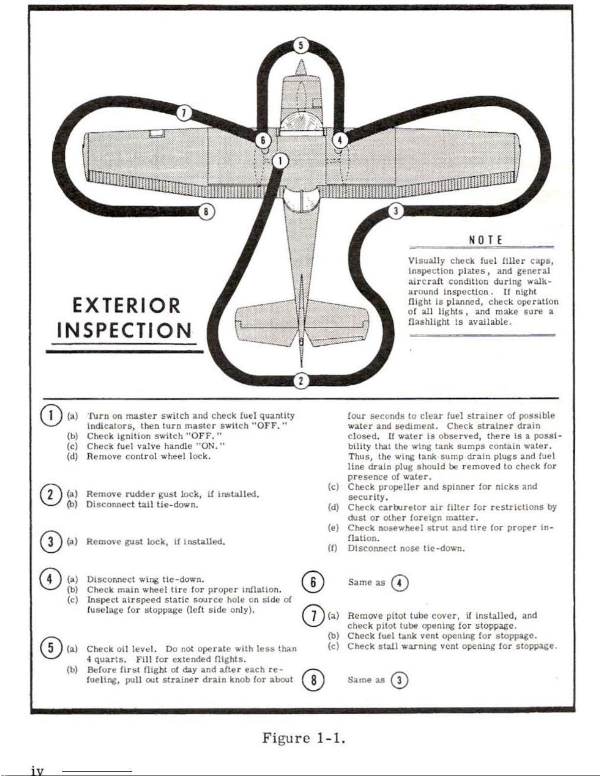
EXTERIOR
INSPECTION
CD
<·>
l\Jrn on
master
switch
and
check
fuel quantity
lndJca.tors,
then
turn
master 1wit
ch "OFF.
"
(b) Check Ignition swHch "OFF.
"
(c
) C
heck
fuel
valve
handle
"ON."
(d)
Rem
ove
conlrol
wheel loc
k.
CD
(a) Remove
rudder
gust
lock, U
11'18lalled.
(b) O
l•coMec
t ta.II tie-down.
0 (a) R
cmo>e
gust
lock, U Insta
lled.
©
(a) Di
sconnect
wing
tie-down.
N 0
TE
Visually
check fuel
Hiler caps,
lnspecllon
pla.J.es, and
gene
rill
a.ircr:i..fl
cond
1tl
on during
walk-
ar o
und lnspecllon.
If
night
flight
ls
pl:lllned,
check operatio
n
of
all
lights,
and make
sure
a
fla
shll,h
t Is aval
lable.
four
seconds
lo
clear
fuel str
ainer
of
possible
wat
er
and
sediment.
Check stra
iner
drain
closed. U water
la observed,
there
ts a possi
-
bilit
y
that
the
wi
ng tank
sumps
contain
waler.
T
hus, the
wing
tank
sump
drain
plugs
and
fuel
line
drain
plug
should
be
removed
to
check
for
presence
of
water.
(c)
Check
propeller
and
spinner for
nicks
and
security
.
(d)
Check carbJ
retor
air
filter
for
resLrlctlons
by
dust
or
other foreign matter
.
(e)
Check
n
ouwheel
s
trut
and tire for
prOl!er tn-
fbllon.
(0
DlscoMect
nose
tie-
down.
Same as ©
(b)
(c)
Check m
ain
wheel
tire
for
proper
inllatlon.
Inspe
ct
airspeed static
source
hole
on
side
of
fus
elage
for stoppag
e (lcrt
side only
).
CD
<·>
R
emOYe
pilot
tu
be
cover,
if
installed,
and
check
pilot
tu
be openi
ng
for
stop
page.
CD<•>
Check
olJ
level.
Do
not
opera
te
with
less
than
4
quarts.
FUI for
extended
Olghts.
(b)
Before
flr~l
night
of
day and
alter
each
re-
(;\
fueli
ng, pu
l1
out stra
iner
drain
knob ror
about
\..V
(b)
Check fuel
tank
vent opening
for
stoppage.
(c)
Check
stall
wa.rnin& v
ent
opening
for
stoppage.
Same as(!)
Fi
gur e
1-1.
iv
Section
I
•
..
,..--~~~~~~~~~~~-
.t?r
....
._
----~~~~....,...~~~~
~
~~~~~~~~~~~~~~tnr
........ _
OPERATING
CHECK
LIST
Cne
of
the
first
steps
in
obtain
ing
the
utmost
performance,
service,
and
flying
enjoyment
from
your
Cessna
is
to
familiarize
your
seli
with
your
airplane
's equ i
pment,
systems,
and
contro
ls .
This
can
best
be
done by
r
eviewing
this
equipment
while
sitting
in
the
airplane.
Th
ose
items
whose
functi on and
ope
rati
on
are
not
obvi
ous
are
covered
in
Section
II.
Section I li
sts,
in
Pil
ot's
Check List
form,
the
steps
necessary
to
operate
your
airplane
efficiently
and
safely.
It
is not a
check
list
in
its
true form
as
it
is
conside
rably longer,
but it
does
cover
briefly
all
of
the
points
that
you
sho
uld
know
for a typical
flight .
The
flig
ht
and
operational characteristics
of
your
airplane
are
no
rma
l
in all respec
ts.
There
ar
e no un
conventiona
l c
hara
cteristics
or
operations
that
need
to
be
mastered.
A
ll
contro
ls
resp
ond
in
the
no r
ma
l way
within
the
en
ti
re
range
of
ope
rati
on. All
airspeeds
mentioned
in
Sections
I and
II
are
indicated
airspeeds.
Corresponding
calibrated
ai
rsp
eeds
may
be
obtained
from
the
Airspeed
Correction
Table
in
Section
V.
BEFORE
ENTERING
THE
AIRPLANE .
{l ) M
ake
an
exterior
insp
ection
in
accordance
with
figure
1- 1.
BEFORE
STARTING
THE
ENGINE .
(1)
Seats
and
Seat
Belts
- -
Adjust
and
loc k.
(2)
Fuel Valv
e Handle
--"ON."
(3)
Brakes
- -
Test
and
set.
(4)
Radios
and
Flashing
Beacon
--
"OFF
. "
STARTING
THE
ENGINE .
{l)
Carbur
etor Heat
--
Cold
.
(2)
Mixture
--
Rich.
1- 1

(3)
Primer
--
As
required.
(4)
Throttle
- -
Op
en 1/4".
(5)
Master
Switch
--"ON."
(6)
Propeller
Area
- - Cl
ear
.
(7) I
gnition Swit
ch --
"S
TART'' (release
when
engine
starts).
(8)
Oil
Pr
ess
ure --
Check.
BEFORE
TAKE-OFF.
(1)
Cab
in Doo
rs
- -
La
tche
d.
(2)
Flight
Cont
rols
--
Check
.
(3)
Trim
Tab
-- "
TAKE-OFF"
setting.
(4)
Throttle
Setting
-- 1700
RPM.
(5)
Engine Instruments
--
Within green
ar
c.
(6)
Suction
Gage
- -
Che
ck (4. 6
to
5. 4
inches
of
mercury)
.
(7)
Carburetor Heat
--
Check
operation.
(8)
Magnet
os - -
Check
(75
RPM
maximum
differential
between
magnetos
.)
(9)
Flight
Instrum
ents
and
Ra
dio
s - -
Se
t.
(10)
Opt
ion
al
Wing
Lev
eler
--"OFF
. "
TAKE-OFF.
NORMAL
TAKE-OFF
.
(1) Wing
Flaps
--
Up.
(2)
Carbureto
r H
eat
--
Cold.
(3)
Throttle
-
Fu
ll "OP
EN."
(4)
Elevator
Control --
Lift
nose
wheel
at
50
MPH.
(5) C
limb Speed
--
73
MPH until
all
obstacles
are cleared,
then
set
up climb
speed
as
shown
in
"NORMAL
CL
IMB"
paragraph.
MAXIMUM
PERFO
RM
ANCE
TAKE-OFF.
(1)
Wing Flaps
--
Up.
(2)
Ca
rburetor Heat
--
Col
d.
(3)
Brakes
--
Hold.
(4)
Throttle --
F
ull "OPEN."
(5)
Brakes
--
Rel
ease
.
(6)
Elevator
Control --
Slightly tail
low.
(7)
Climb
Speed
- -
64
MPH (with
obstacles
ahead)
.
CLIMB.
NORMAL
CLIMB
.
(1)
Air
Speed - - 75
to
80
MPH.
1
-2

(2) P
ower
--
Full
throttle
..
(3)
Mixture
--
Rich
(unless
engine
is
rou
gh).
MA
XIMUM PERFORMANCE
CLIMB
.
(1)
Air
Speed
--
73
MPH.
(2) Power - -
Full
throttle.
(3)
Mixture
- -
Rich
(unless
engine
is
r ough).
CRUISING.
(1)
Power
- - 2000
lo
2750
RPM
.
(2)
Elevator
Trim
--
Adjust.
(3) Mi
xture
--
Lean
to
maximum
RPM.
BEFORE
LANDING.
(1)
Mixture
- -
Rich.
(2)
Carburetor
Heat
--
Apply
full
heat before
closing throttle
.
(3)
Airspeed
- -
65
to
75
MPH.
(4) Wing
Flaps
- -
As
desired
below
100
MPH.
(5)
Airspeed
- - 60 to 70
MPH
(flaps
extend
ed).
NORMAL
LANDING
.
(1)
Touch
Down - -
Main
wheels
first
.
(2)
Landing Roll
- -
Lower
nose
wheel gently.
(3)
Brakin
g - -
Minimum requir
ed.
AFTER
LANDING.
(1) Wing
Flaps
--
Up.
(2)
Carburetor
Heat
- - Cold.
SECURE
AIRCRAFT.
(1)
Mixtur
e - -
Idle
cut-off.
(2) All
Switches
-- Off.
(3)
Parking Brake
--
Set.
(4)
Contr
ol Lo
ck
--
Ins
talled.
1-
3

INSTRUMENT
PANEL
2 3 4 5 6 7 8 9
10
11
12
I.
Turn
Coordinator
(Opl
.)
2.
Air
speed
tnd1cator
3.
Directional
Cyro
(
Opt.
)
4 .
Gyro
H oriz.on
(Opt.
)
5.
Clock
(Opt.
)
6.
Aircraft
Registratt on Number
7.
Vert
ical Speed lndlcuor
(Opt.)
8.
Altlmeler
9.
Muk
er
Beacon Lights/Radio
Tran
sm1tt
r>r
St!lec tor Switch
I 0.
Omni Cou
rs e I
ndica
tor
(Op
t. )
11. Rc:ir View Mlrror (
Opt.)
l 2.
Rad
ios (Opt.
)
1-4
13. Tach
omet
er
14.
Le!t
Fuel
Quanttty
Ind
icato
r
IS
.
Bea
ring lndicator
(Opt.)
16.
Riaht F
uel
Quantity Ind
ica
to r
17.
Sucllon
Ca~e
(Opt.)
18. Ammeter
19.
Oil
Temperature Gage
20.
011
Pressu
re
G;ige
21. Map Compar
tment
22.
Cabin
Atr
and H
eat
Control
Knobs
23.
W
I~
flap
Swi
tch
24.
Cigar Lighter
(Opt.)
25.
Mixt
ure
Control
Knob
Figure
2-1.
13 14
15
16
17
26.
Wing Leveler Co
ntrol Knob
(Opt.)
27. Mic r
ophone (Opt.
)
28.
Throttle
29. Elevator
Tnm
Control Wheel
30.
Carburetor
Heat Control
Kn
ob
31.
Electr
ical Swllches
32. Fuses
33.
Rad
io
Dial Lighl
Rheos
tat
34.
Altern2tor
Circuit
Break.er
3$.
lgn1tlon. 'Starter
Switch
36.
Master
Switch
37.
En.gtne
Primer
38. Parking
Brake
Kn
ob

Se
c
tion
II
brr
111:====================~~~~~~~~~~-·brr
.......
_
DESCRIPTION
AND
OPERATING
DETAILS
The foll
owing
paragraphs
describe the
systems
an
d e
quipment
wh
ose
function
and
operation
is not
obvious
when
sitting
in the
airplane.
Th
is
section also
covers
in
somewhat grea
ter
detail
some
of
the
items
listed
in
Check
List
form
in
Section I that
require further
exp
lanatio
n.
FUEL
SYSTEM.
Fu
el
is
supplied
to
the
engine
from
two
tanks, one
in
each
win
g.
From
thes e
tanks, fuel
flows by gr
avity
thr ough a
fuel
shut
off valve and
fuel
strainer
to the carbur
eto
r.
R
efe
r to
figure
2-2
for fuel
quantity
data
.
For fuel
syste
m
service
i
nformation,
refer
to
Lubricati
on
and
Servicing Pr
ocedures
in
Section
IV.
FUEL
STRAINER
DRAIN
KNOB
.
Refer to fu el
strainer
servicing procedure,
Section
IV.
FUEL
QUANTITY
DATA
(U.S.
GALLONS)
USAB
LE FUEL
UNUSABLE
TOTAL
TANKS ALL
FLIGHT
FUEL
FUEL
COND
ITIO
NS
VOLUME
TWO,
STANDARD WING
22. 5 3. 5
26.0
{13
GAL. EACH)
TWO, LONG
RA
GE WING
35.0
3. 0 38. 0
(19 GAL. EACH)
F
igu
re
2- 2.
2-1

VENT
2-2
llnllllt;~jjlj~~~llll~llll~l~ll~l
fjjj~~;~ill
1~~l1
~11lli
LEFT
FUEL
TANK
!W;;':
i
:
!!
!
!!;!!!!
!!!!~ll!lllllllllllilill!illlilllilllll
RI
GHT
FUEL
TANK
°
FUEL
0
FUEL SHUTOFF
22.s GA
lS
VALVE
ON~
CODE
..._._.,.._o,_
•-•
...,
o !;;;;;;;;;;;;!
FUEL
SUPPL
Y
FUEL
SYSTEM
···
·SCHEMATIC
····
CARBURETOR
TO
ENGINE
CYLINDERS
....
Figu
r e 2- 3.
c:::::J
VENT
MECHANI
CAL
LINKAGE
THROT
TL
E
...
--1-rfl
......
~
<
......
------
~
MIXTURE
CO
NTROL
KNOB

ELECTRICAL SYSTEM.
Electrical
energy
is
supplied
by a 14-volt,
direct-current
sys
tem
p
owered
by
an engine
-driv
en
alternator
(see
figure
2-4
). A
12-volt
battery
is
located
on the right ,
forward side
of the
firewall
just
inside
the
cowl
access
doo
r.
Power
is
supplied through a sing
le
bus
bar
; a
master
switc
h controls
this
power to
all cir
cuits,
except
the engine ignition
sys-
t
em,
opti onal clock an d optional flight
hour
recorder
(operative
only wh
en
the engine
is operatin
g).
AMMETER.
The amm
ete
r indicat
es
th e fl
ow
of
current,
in
amperes,
from
the
alte
rn
ato
r to the
battery
or from
the b
atte
r y
to
the a
irc
r aft el
ectrical
system.
Wh
en the engine is ope
ratin
g and the
maste
r switch is
"ON,"
the
ammete
r indic at
es
the
chargi
ng
rate
applied to the
battery
.
In
the
event
the alternator
is
not functioning or the el
ect
rical load exceeds the
output of the alternator , the am
meter
indi
cates
the disc
har
ge r ate of the
bat
tery
.
FUSES
AND
CIRCUIT BREAKERS.
Fuses
on
the left lo;.ver po
rti
on
of the inst
rument
panel
protect
the
ma
jori
ty of el
ectrica
l c
ircuits
in the
airp
lane. Labeling bel
ow
eac
h fu
se
r
etainer
indi
cates
the circuit s
protec
ted by the fu
ses
. Fu
se capa
city is
shown on
each
fuse
reta
iner
cap.
Fuses
are remove
d by
pressing
the
fuse r
etainers
inward and rotating them
counterc
lockwise until th
ey dis-
engage. The faully fuse may then be lifted out and
replaced.
Spare
fuses
are h
eld
in a c
lip
on the i
nsid
e of the map compartment
doo
r.
NOTE
A
special
"SLO-BLO"
fuse
protects
the wing flaps circuit.
lf
this
fuse
is
replaced,
care
shou
ld
be
tak
en
to
assure
that
the
replacement
fuse
is
of the proper type and capa-
ci
ty
. A "S
LO-BLO"
fuse
is
identified by an integr ally
mounted
spri
ng encirc
ling the
fus
e element.
Tw
o ad
diti
onal
fuses
are localed
adjace
nt
to
the
bat
ter
y;
one
fuse
pro-
t
ects
the
battery
contact
or
closing
circuit, and the oth
er
fuse
protects
the
optional clock an d optional flig
ht hour recorder circuits.
The
airp
lane u
tilizes
thre
e c
ircuil·breake
rs f
or
circ
uit
protectio
n. A
"push-to-r
ese
t" cir
cuit breaker
(labeled "
GE
N") is located
on the left side
of the ins
trum
ent
near
the fu
ses
and prot
ects
the
alte
rnator circuit.
The
2-3

ELECTRICAL
SYSTEM
-
I A
nERY
ALTERNATO
R FIELD
CIRCUIT
BREAKER
CIG
AR LIGHTER (OPT(
(
WI
TH
CIR
CUIT BREA
KER!
GROUND SERV
ICE
P
LU
G R
ECEPTACLE (OPn
CODE
Q)
CIRCUIT
BREAKER
•
FUSE
-i+ DIODE
-lf- CAPACITOR
MAGNETOS
'\l\N
RESISTOR
Figure
2-4.
2
-4
SCHEMATIC
TO W
ING
FLAP
SYSTEM
TO LA
ND
ING AND
TAXI LIGHTS (OPT!
TO
FLASHING
BEACON
(OPT!
TO PITOT
HE
AT
SYSTE"'
(OPl)
TO
NAVIGATION
LIGHTS
AND
OPTIONAL
CONT
RO L
WHEEL MAP LIGH
TS
TO DOME LIG
HT
TO
RADIO (OPT(
TO RADIO (OPTI
TO
RADIO
(OPT!
TO
OPTIO
NAL
TURN
COORDINATOR
OR
OPTIONAL
TURN-AND.
BANK IND
ICAT
OR
TO IN
STRU
MENT AND
COMPASS LIGHTS
TO
fUEl QUAN
TIT
Y
INDICA
TORS

alternator
field
and
wiring
is
protected
by
an
automatically
resetting cir-
cuit
breaker
mounted
behind
the le
ft
side
of
the
instrument panel.
The
cigar
lighter
has a manually
reset
type
circuit
breaker
mounted
dire
ctly
on the
back
of
the lighter behind
the
instrument
panel.
CONTROL
WHE
EL
MAP
LIGHT (OPT
).
A
map
light
may
be
mounted
on the
bottom
of
the
pilot
's
cont
r ol wheel.
The
light
illuminates
the lower
portion
of
the
cab
in
just forward
of the
-pilot and
is
helpful
when
checking
maps
and other
flight
data
during ni
ght
ope
rations.
To o
perate
the light,
fir
st
turn
on the "NAV LIGHTS"
switch,
th
en
adjust
the
map lig
ht's
intensity
wit
h the
knurl
ed rheostat
knob l
ocated
at
the bottom
of the
co
ntrol
wheel.
FLASHI
NG
BEACO
N (
OPT)
.
The flashin
g b
eacon
should not
be used
when flying through
clouds
or
overcast;
the
flashing light reflected
from
water
dropl
ets
or
par
ticles
in
the
atmosphere,
particularly
at
night,
can pro
duce
vertigo
an
d l
oss
of
or
ientation.
CABIN HEATI NG
AND
VENTILATING SYSTEM.
The temper
ature and
volume
of
airflow
into the cab
in
can
be
r
egulated
•
to any degr
ee desi
r ed by
manip
ula
tion of
the
push-pull
"C
AB
IN
HEAT"
and
"CABIN AIR" knobs.
Heated fresh
air
and outside
air
are
blende
d in a
cabin manifold
just
aft
of the
firewall
by
adjus
tment
of
the
heat
and
air
co
ntrols;
this
air
is
then
vented
into
the cabin from outlets in the
cabin
manifo
ld
near
the
pil
ot's
and
passen
ge
r's
fee
t.
Wi
ndshield
defrost
air
is
also
supplied
by
a
duct
leading
from
the
manifold
.
A
separate
adjustable
ventilator
near
each upper
corner
of the wind-
sh
ield
suppli
es
additional outside air
to the
pil
ot
and
passenger.
PAR
KI
NG
BRA
KE
SYS
TEM.
To
set parki
ng
brake,
pull
out
on
the
parking brak
e knob,
apply
and
rel
ease
t.oe pressure
to
the
pedals,
and
then
r el
ease the
parking
brake
knob. To rel
ease
the
pa
rking
brak
e,
app
ly
and rel
ease
toe pressu
re on
th
e pedals while
checking
to
see
that
the
parking brak
e knob
is
full
in.
2- 5

2-6
TAXIING
USE
UP
AILERON
ON
LEFT
WlNG AND
NEUTRAL ELEVATOR
•
WIND
DIRECTION
DIAGRAM
...
USE UP
All.ERON
ON
RIGHT
WlNG
AND
NEUTRAL ELEVATOR
NOTE
Strong
quartering
tallwlnds
require
cauUoo.
Av
oid
sudden
bu.rat.
of
the
throttle
and
ahar
p
braking
when tile
airplane
i..
In
tlllB
attit
ude.
Use lhe
ate
era.ble no
se
wheel and
rudder
to
malntain
dlrection.
Figure
2-5.

STARTING
ENGINE.
Ordinarily
the
engine
starts
easily
with
one
or
two
strokes
of p
rim
er
in
warm
temperatures
to
six
strokes
in cold
weather,
with
the
thrott
le
open
appro
ximat
ely 1/ 4 inch. In e
xtr
eme
ly cold
temperatures,
it
may
be necess
ary
to continue
primin
g w
hile cranking
.
Weak
intermittent
explosions
followed by
puffs
of
black
smoke from
the exhau st
stack
indicate
overpriming
or flooding .
Excess
fuel can be
cleared from
the combusti
on c
hambers
by the following
procedure:
Set
the
mixture control
in
full l
ean
pos
iti
on,
thr
ott
le
full
ope
n, and
crank
the
engine
thr
ough
severa
l r
evo
lution
s with th e
start
er
. R
epe
at
the
s
tarting pr
oce
dur
e without any
additional pri
ming.
If
the engine
is
und e
rprim
ed (mo
st
lik
ely
in cold w
eat
her with a cold
engine)
it
will
not
fire
at
all
, and
additional
prim
ing
will
be
necessary.
As
soon as
the cylind
er s
begin
to
fire,
open
the
throttle
slightly
to
keep
it
runnin
g.
After
starting,
if
the o
il
gage does not
begin
to show
pr
essure
with-
in
30
seconds
in
the
summertim
e and abo
ut
twice
that
long
in very cold
w
ea
ther, stop
engine
and
investiga
te. L
ack
of
oil
pressure
can
cause
serious
engine
damage.
After startin
g,
avoid
the use
of carbur
eto
r heat
unl
ess ici
ng conditi
ons
preva
il.
TAXIING.
Wh
en
taxiing,
it
is
important that
speed
and
use
of
brakes
be
held
to
a
minimum
and
that
all
controls
be
utili
zed
(see
taxiing
diagram,
figure
2-5)
to
maintain
dir
ectio
nal contr
ol
and
balance
.
Taxii
ng
over loose
gravel
or
cinders
shou
ld
be done
at
low
engine
speed
to
avoid abr
asion
and
sto
ne
dam
age
to
the
propeller
tips
.
Th
e n
ose
wheel
is
designed
to
automatically
center stra
ight
ahead
when
the nose
str
ut
is
fully extended.
In the
event
the
nose
strut
is
ove
r -
inflat
ed
and
the
airplane
is loa
ded
to a rearward
cente
r of
gra
vity pos
i-
ti
on,
it
may
be
n
ecessary
to
partially
compress
the
str
ut
to per
mit
steer
-
ing.
This
can
be
accomplis
hed
prior
to
taxiing
by
depr
essing
the a
irplan
e
n
ose
(by
hand
) or du
ring
taxi
by s
harpl
y applying
brakes
.
2-7

BEFORE
TAKE-OFF.
WARM-UP
.
Mo
st
of
the
warm-up
will
have
been
conducted
during
taxi,
and
addi
-
ti
onal
warm-up
before
take-ofi
shou
ld
be
restricted
to
the
checks out
-
lined
in
Section
I.
Since
the
engine
is
closely
cowled
for
efficient
in-flight
cooling,
pr
ecau
tions
shou
ld
be
taken
to
avoid
overheating
on
the
ground.
MAGNETO
CHECK.
The magneto
check shou
ld
be
made
at
1700
RPM
as
follows: Move the
ignition
switch
first
to
"R"
position
and
note
RPM.
Then
move
switch
back
to
"BOTH"
position
to
clear
the
other
set
of
plugs. Then
move
switch
to "L"
position
and
note
RPM.
The
difference
between
the
two
magnetos
oper
ated
individually
should
not
be
more
than 75
RPM.
If
there
is
a doubt
concerning
the
operation
of the i
gnition
system,
RPM
checks
at
higher
engine
speeds
will
usually
confirm
whether a defici
ency
exists.
An
abs
ence
of RPM
drop
may
be
an
indicati
on of
faulty
grou
nding of
one
side
of the
ignition
system
or
shou
ld
be
cause
for
suspicion
that
the
magneto
timing
is
set
in
advance
of the
setting
specified
.
TAKE-OFF.
POWER
CHECKS
.
It
is
important
to
check
full-throttle
engine o
peration
early
in lhe
take
-
off
run.
Any
signs
of
rough
engine
operation
or sluggish en
gine
accelera
-
tion
is
good
cause
for discontinuing the
take
-off.
If
t
his
occu
rs,
you
are
justified
in
making
a th
orough
full-throttle,
static
runup
before
another
t
ake-off
is
attempted.
The
engine
should
run
smooth
ly and
turn approxi
-
mately
2500 to 2600
RPM
with
carburetor
heat
off.
Full
throttle runups
ove
r l
oose
gravel
are
especially
harmful
to
pro-
peller
tips.
When
take-offs
must
be
made
over
a g
ravel
surface,
it
is
very
important
that
the
throttle
be
advanced
slowly.
This
allows
the
air
-
pl
ane
to s
tart
rolling
before
high
RPM
is
deve
loped,
and
the
gravel
will
be
blown
back
of
the
propeller
rath
er
than
pulled
into
it.
When unavoi
d-
2-8
 Loading...